Coordinated Control of Aichi Microgrid for Efficient Power Management Using Novel Set Point Weighting Iterative Learning Controller


Abstract
1. Introduction
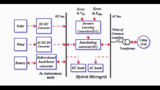
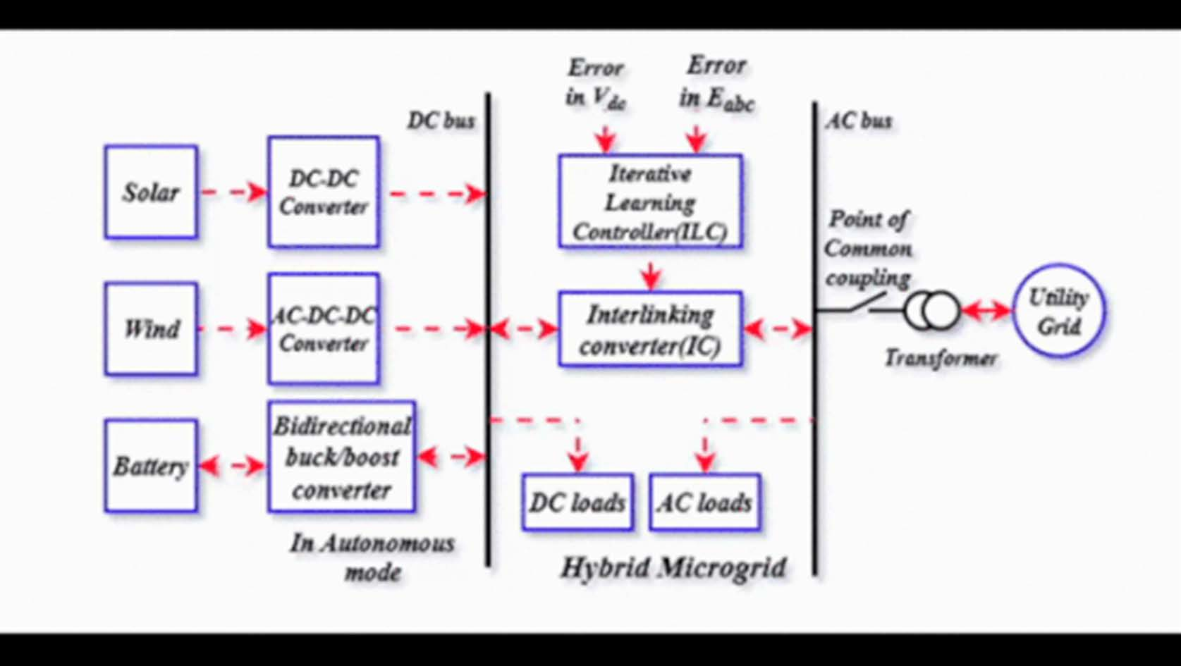
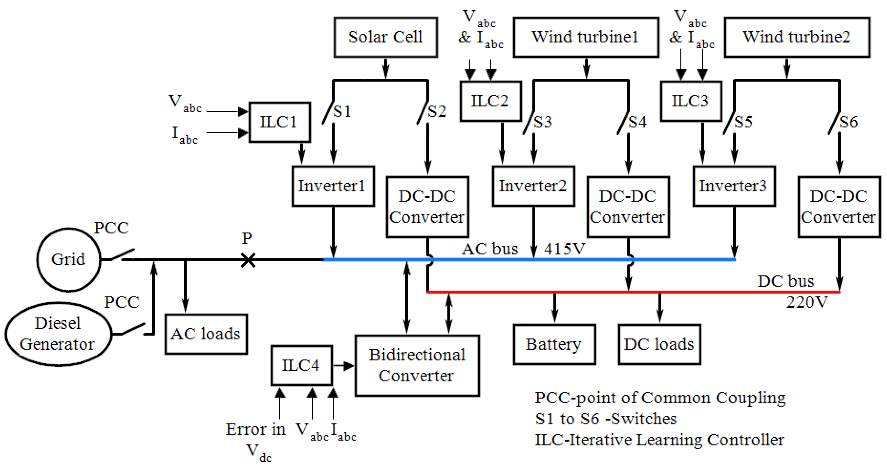
2. Formation of Micro Grid
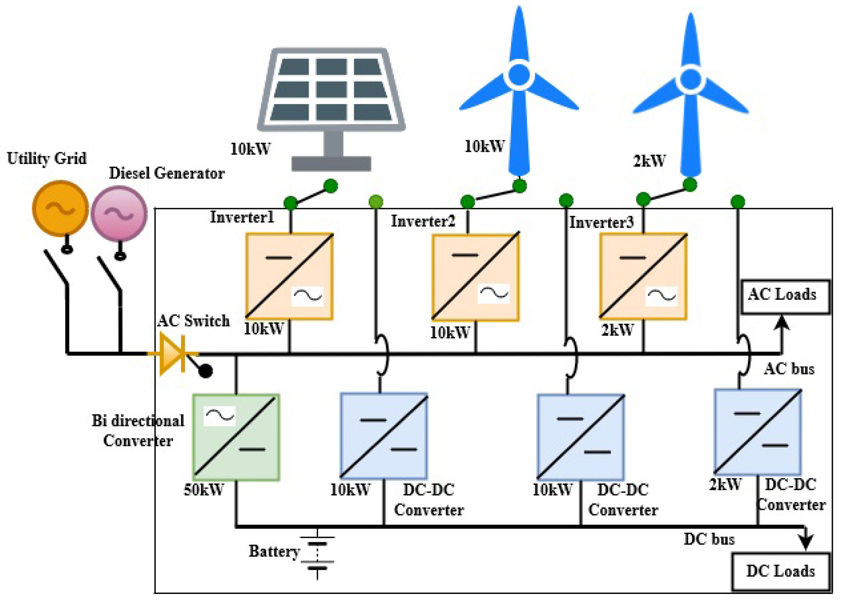
2.1. System Description
2.2. System Development
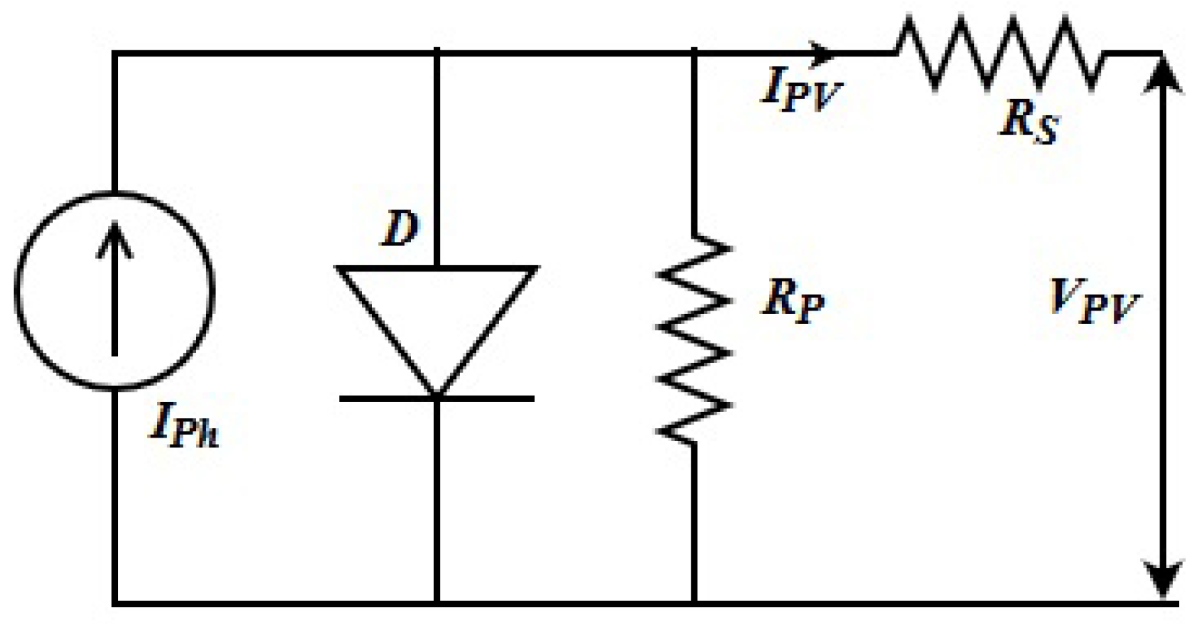
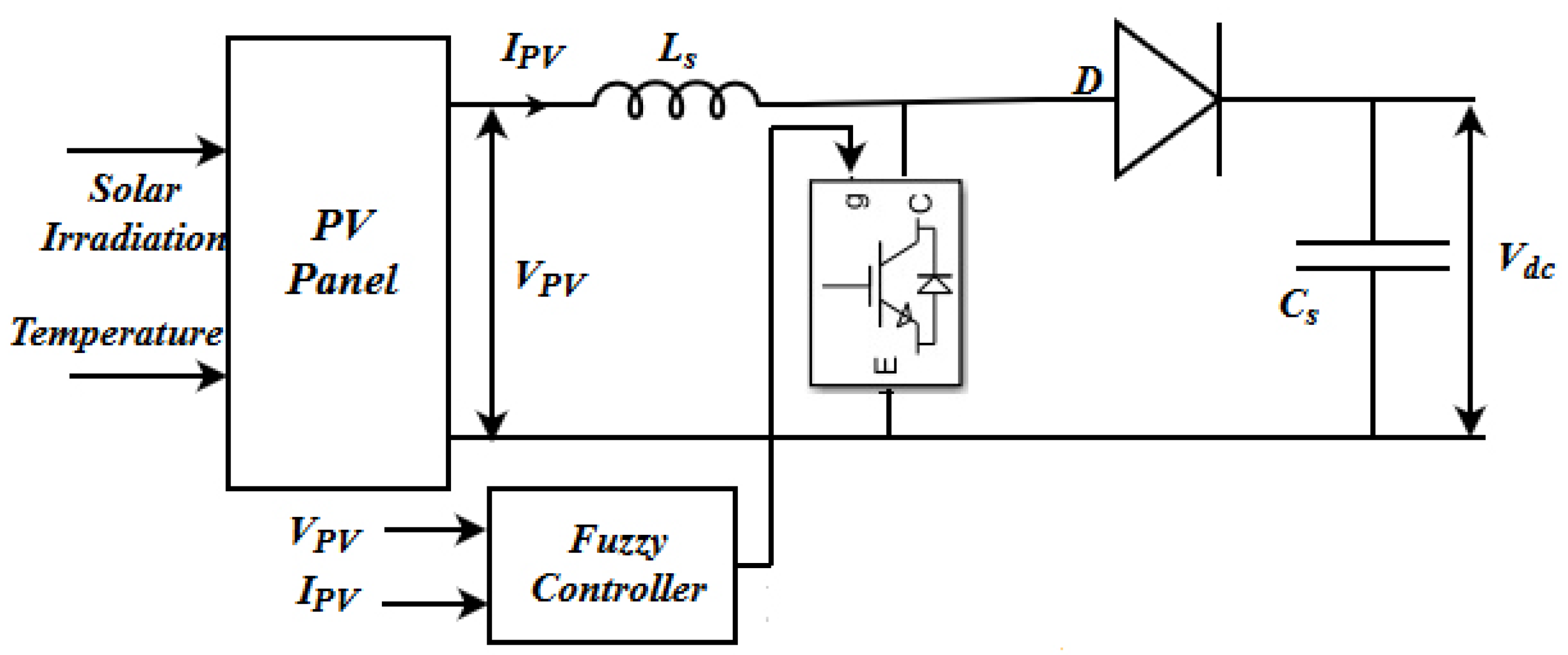
2.2.1. Solar Cell
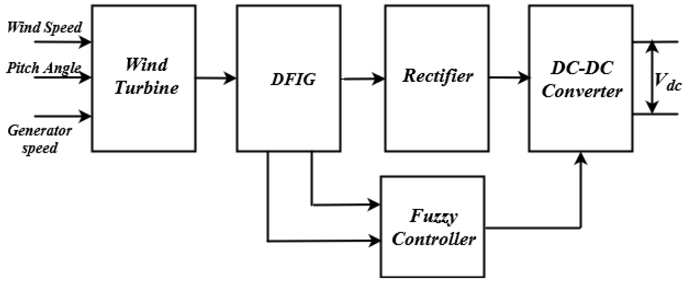
2.2.2. Wind System
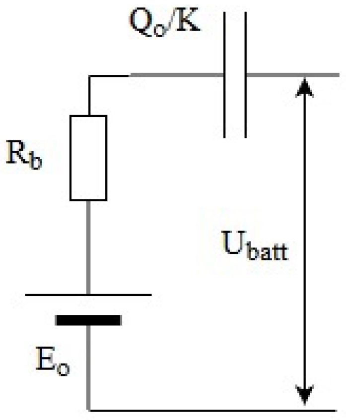
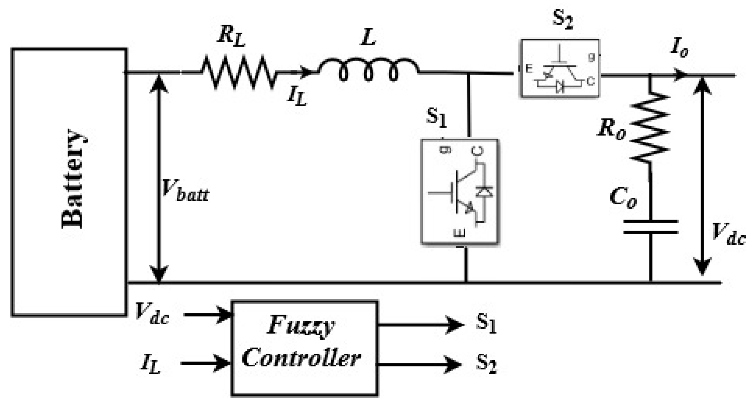
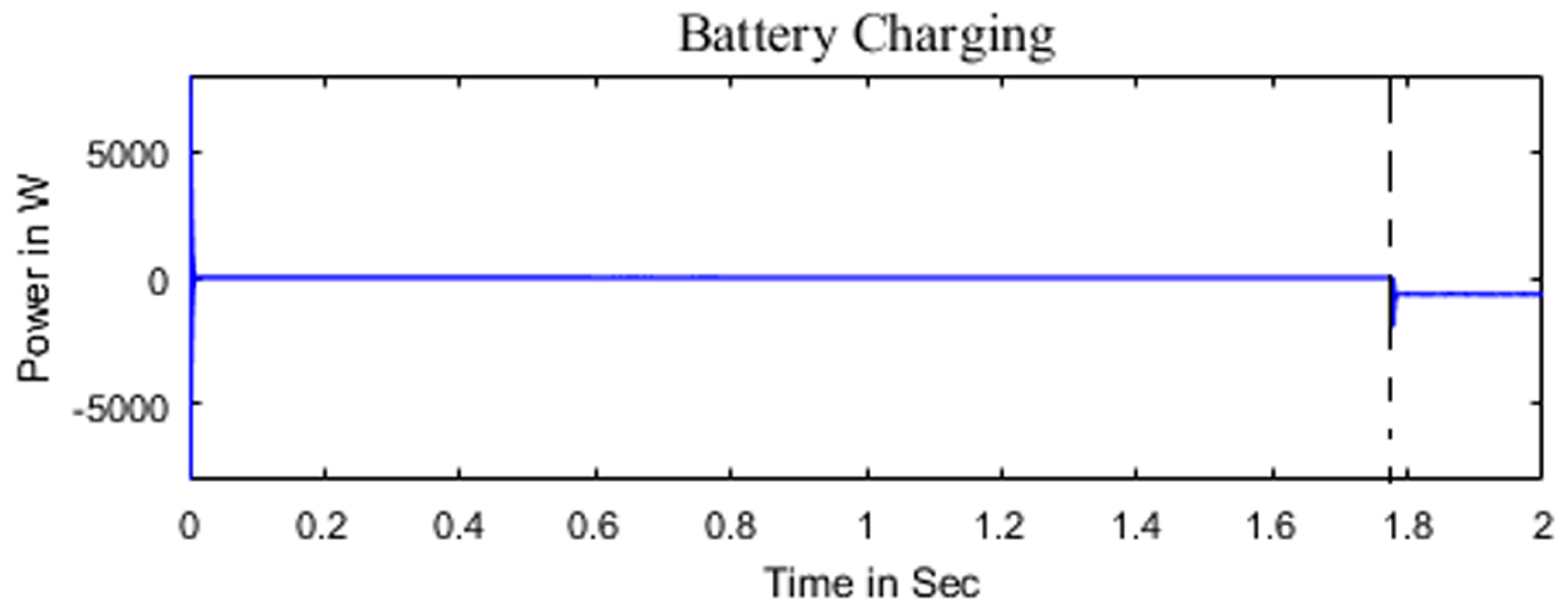
2.2.3. Battery
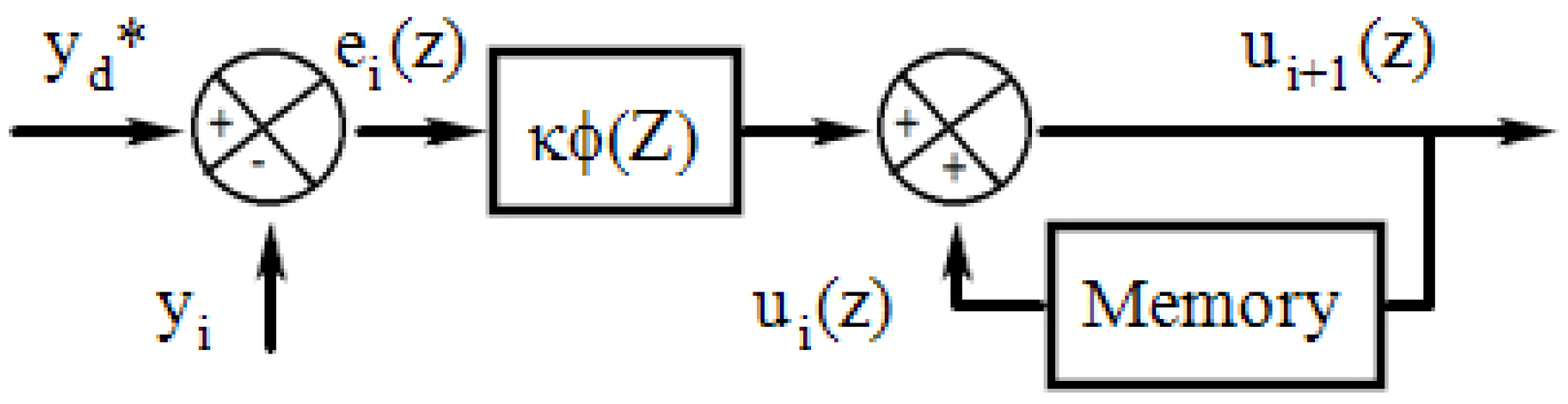
3. Iterative Learning Controller
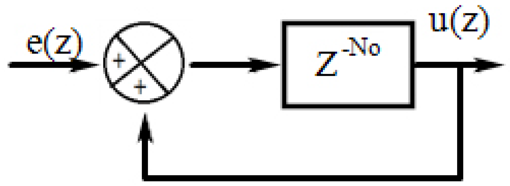
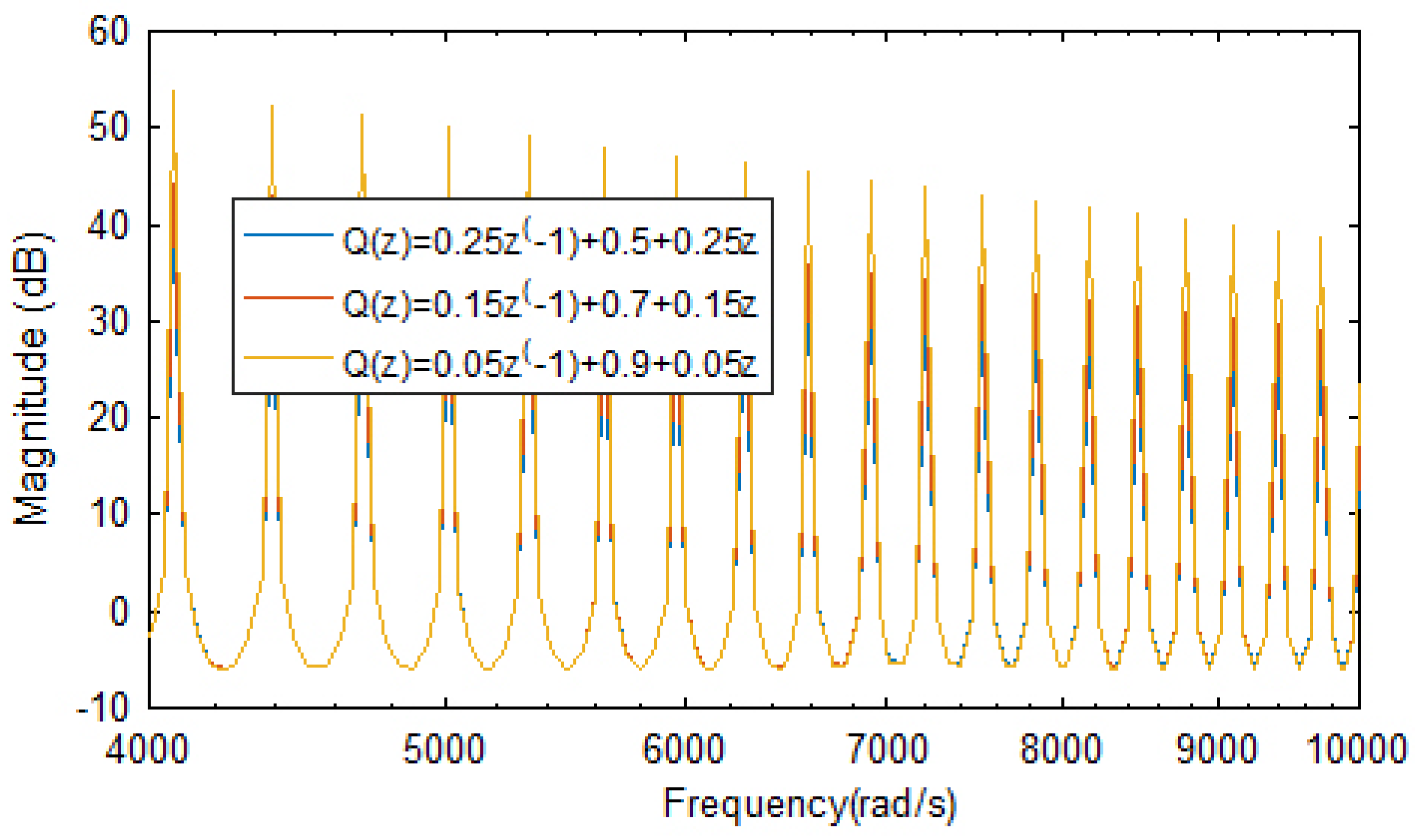
3.1. Selection of ILC Type
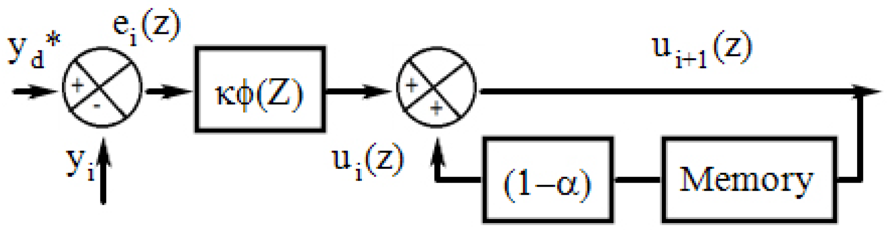
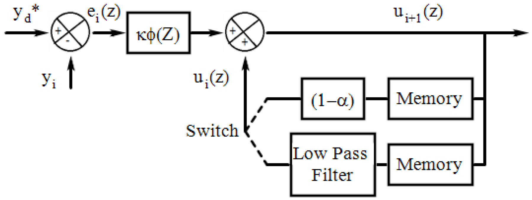
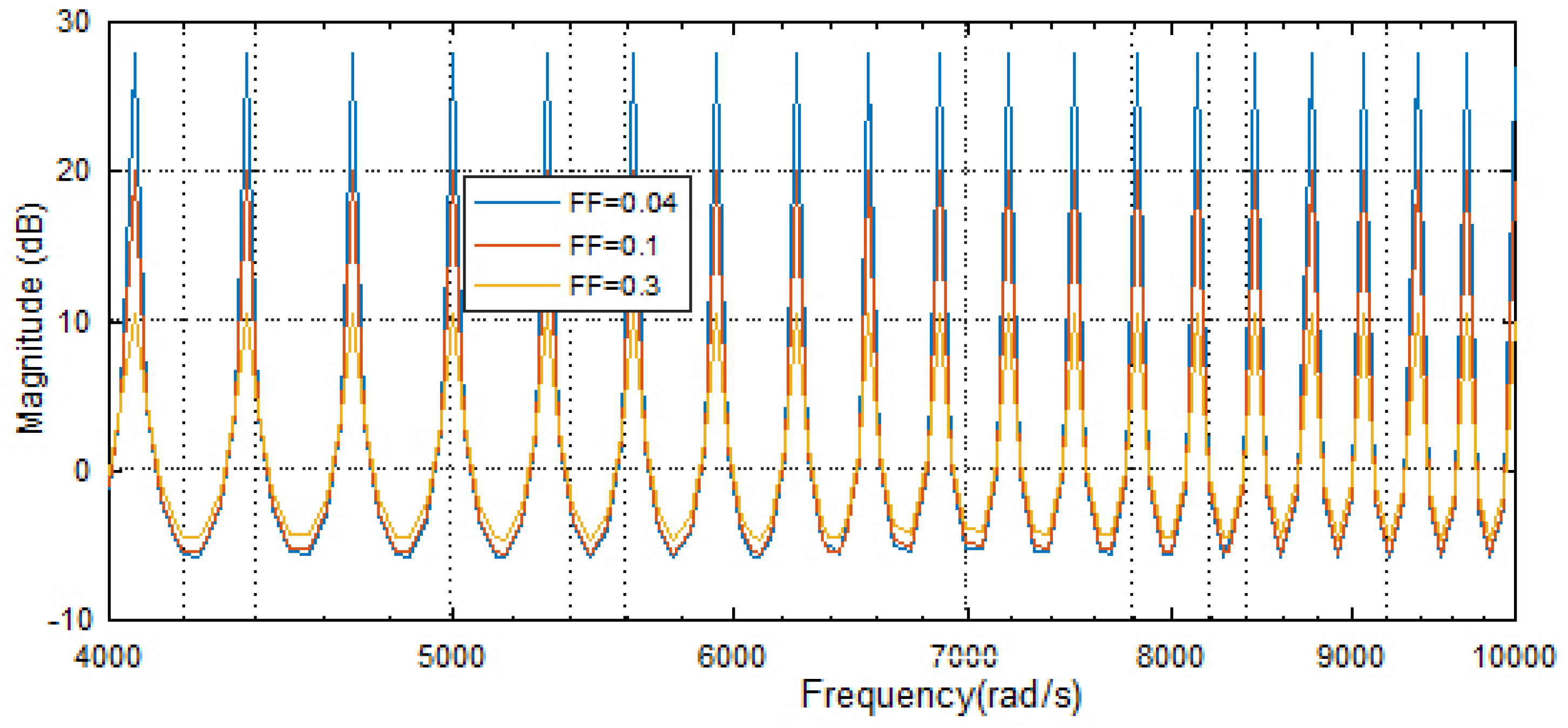
3.2. Selection of Forgetting Factor Value
- To effectively synchronize the microgrid AC power with the main grid by ensuring the high quality and efficient power exchange between the microgrid and the utility grid.
- To maintain the constant DC-link voltage by minimizing the error between the measured voltage and the reference voltage under wind dynamics, solar insolation.
- To maintain the system stability during mode transition between grid connected and autonomous mode or vice versa. Due to the above highlighted advantages of ILC, it has been implemented in the system as discussed in the next section.
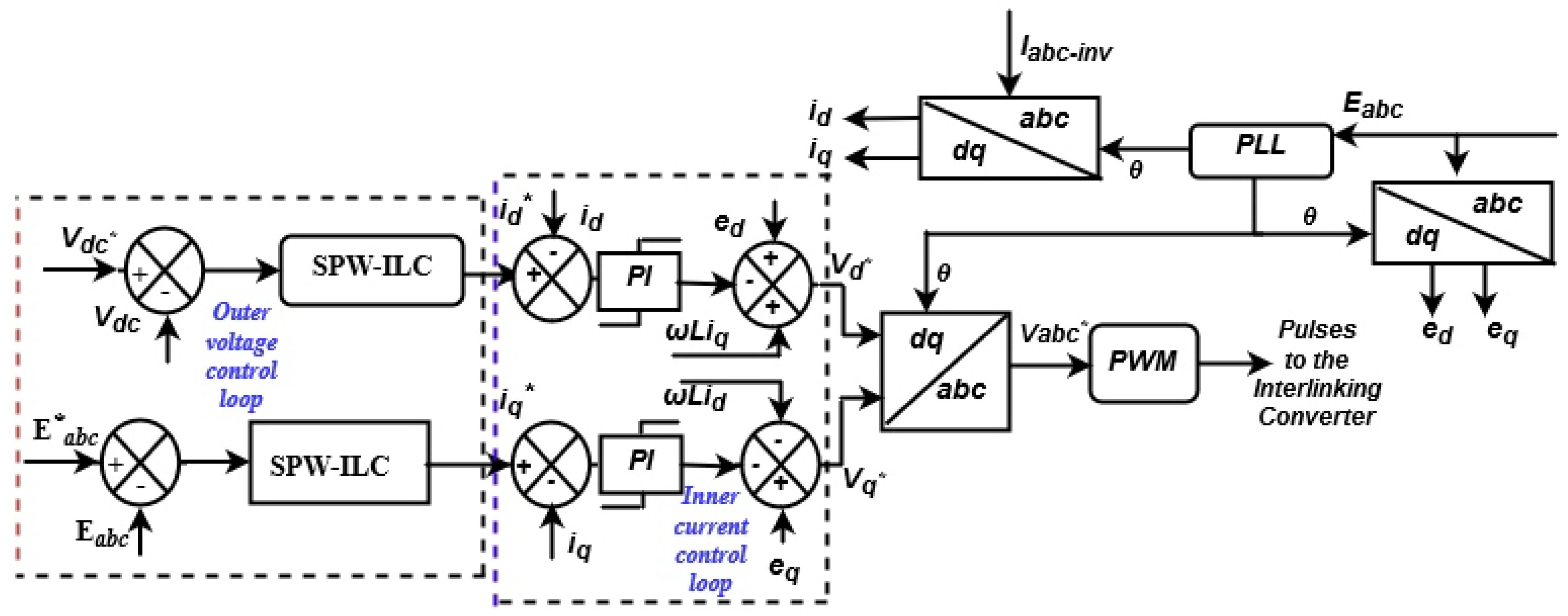
4. Implementation of SPW-ILC in Micro Grid
- (1)
- Control of source or machine side converter (MSC)
- (2)
- Control of Grid side converter (GSC).
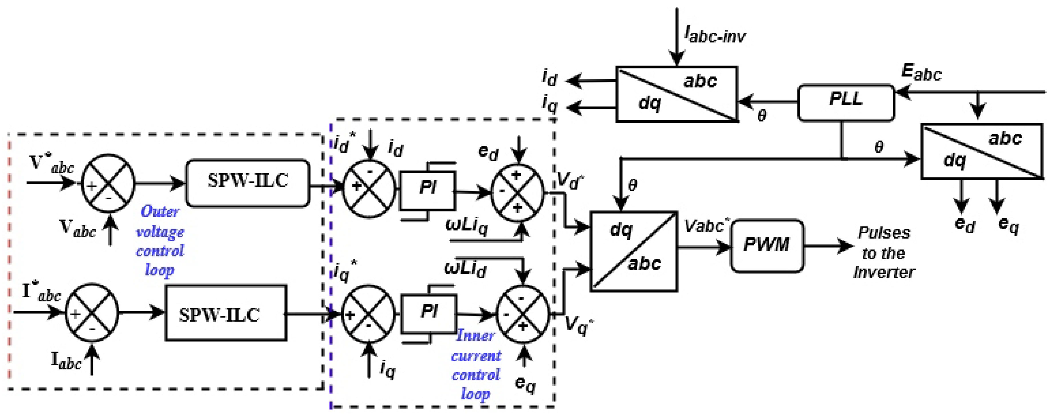
4.1. Inner Control Loop for Current Regulation
4.2. Outer Control Loop for Voltage Regulation
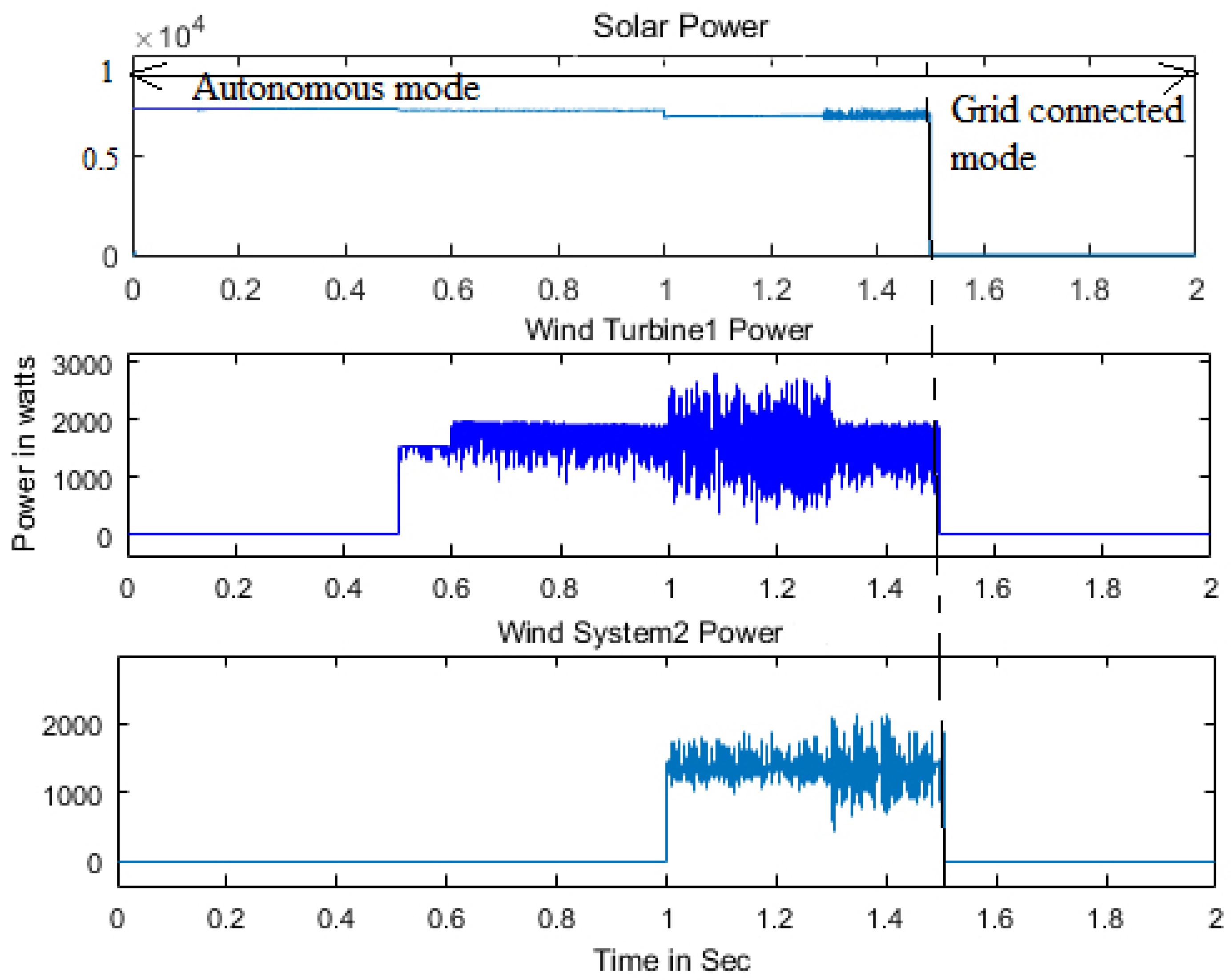
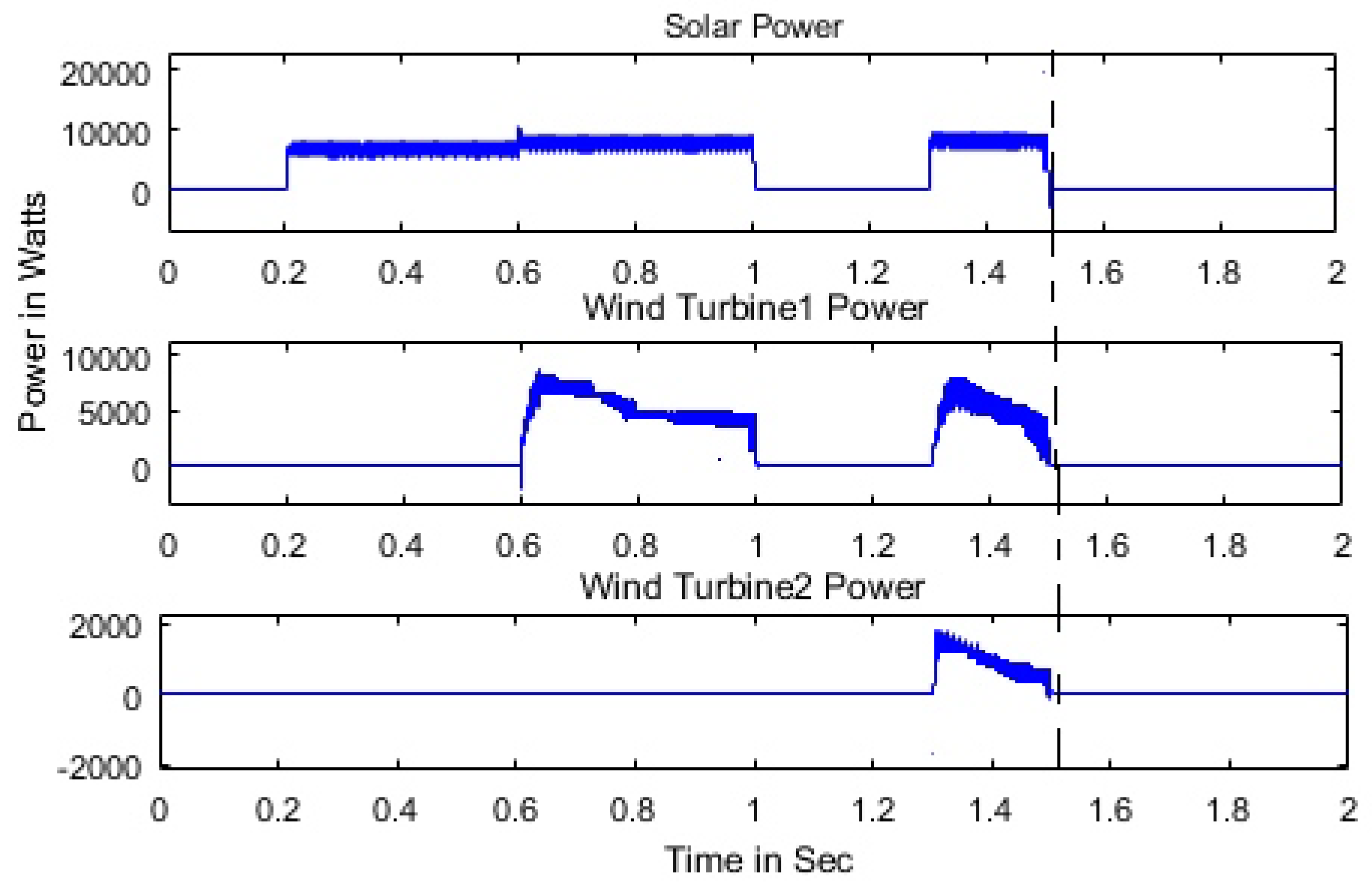
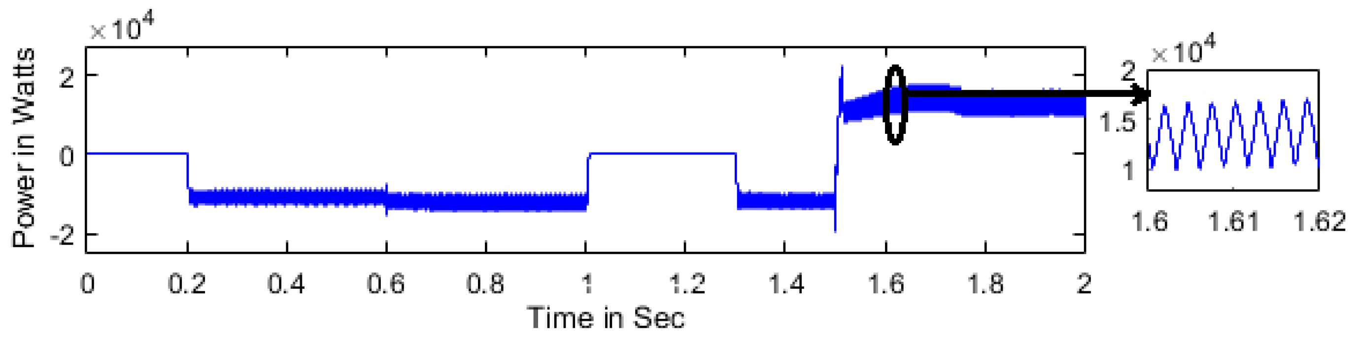
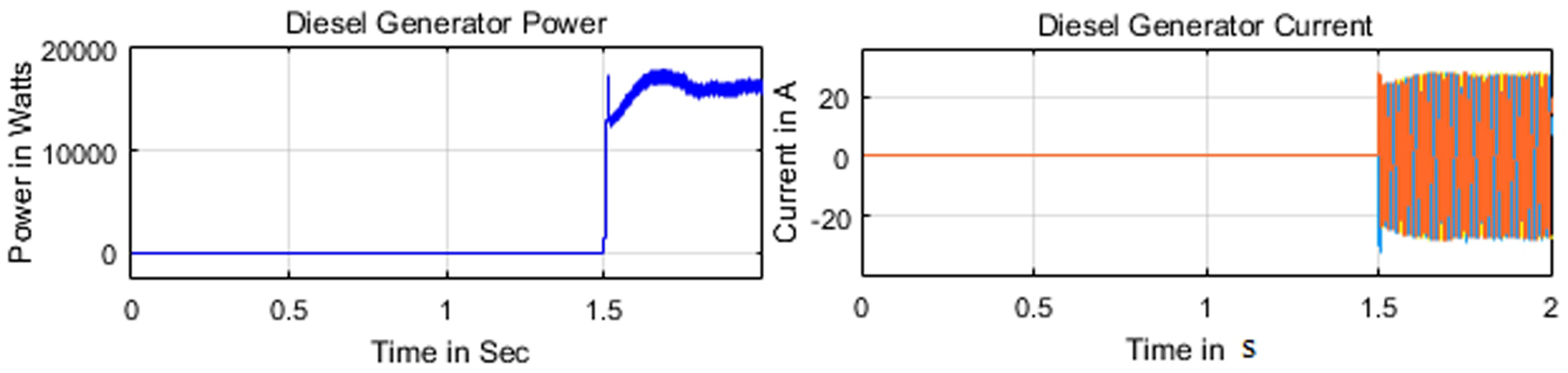
5. Results and Discussion
6. Conclusions
Author Contributions
Funding
Acknowledgments
Conflicts of Interest
References
- Loh, P.C.; Li, D.; Chai, Y.K.; Blaabjerg, F. Hybrid AC-DC microgrids with energy storages and progressive energy flow tuning. IEEE Trans. Power Electron. 2013, 28, 1533–1543. [Google Scholar] [CrossRef]
- Loh, P.C.; Li, D.; Chai, Y.K.; Blaabjerg, F. Autonomous operation of hybrid microgrid with AC and DC subgrids. IEEE Trans. Power Electron. 2013, 28, 2214–2223. [Google Scholar] [CrossRef]
- Eghtedarpour, N.; Farjah, E. Power control and management in a hybrid AC/DC microgrid. IEEE Trans. Smart Grid 2014, 5, 1494–1505. [Google Scholar] [CrossRef]
- Xia, Y.; Peng, Y.; Yang, P.; Yu, M.; Wei, W. Distributed coordination control for multiple bidirectional power converters in a hybrid AC/DC microgrid. IEEE Trans. Power Electron. 2017, 32, 4949–4959. [Google Scholar] [CrossRef]
- Rahman, M.S.; Hossain, M.J.; Lu, J. Coordinated control of three-phase AC and DC type EV-ESSS for efficient hybrid microgrid operations. Energy Convers. Manag. 2016, 122, 488–503. [Google Scholar] [CrossRef]
- Wang, P.; Jin, C.; Zhu, D.; Tang, Y.; Loh, P.C.; Choo, F.H. Distributed control for autonomous operation of a three-port AC/DC/DS hybrid microgrid. IEEE Trans. Ind. Electron. 2015, 62, 1279–1290. [Google Scholar] [CrossRef]
- Majumder, R. A hybrid microgrid with DC connection at back to back converters. IEEE Trans. Smart Grid 2014, 5, 251–259. [Google Scholar] [CrossRef]
- Liu, X.; Wang, P.; Loh, P.C. A hybrid AC/DC microgrid and its coordination control. IEEE Trans. Smart Grid 2011, 2, 278–286. [Google Scholar]
- Hosseinzadeh, M.; Salmasi, F.R. Robust optimal power management system for a hybrid AC/DC microgrid. IEEE Trans. Sustain. Energy 2015, 6, 675–687. [Google Scholar] [CrossRef]
- Baboli, P.T.; Shahparasti, M.; Moghaddam, M.P.; Haghifam, M.R.; Mohamadian, M. Energy management and operation modelling of hybrid AC-DC microgrid. IET Gener. Transm. Distrib. 2014, 8, 1700–1711. [Google Scholar] [CrossRef]
- Xiao, H.; Luo, A.; Shuai, Z.; Jin, G.; Huang, Y. An improved control method for multiple bidirectional power converters in hybrid AC/DC microgrid. IEEE Trans. Smart Grid 2016, 7, 340–347. [Google Scholar] [CrossRef]
- Eajal, A.A.; Abdelwahed, M.A.; El-Saadany, E.F.; Ponnambalam, K. A unified approach to the power flow analysis of AC/DC hybrid microgrids. IEEE Trans. Sustain. Energy 2016, 7, 1145–1158. [Google Scholar] [CrossRef]
- Che, L.; Shahidehpour, M.; Alabdulwahab, A.; Al-Turki, Y. Hierarchical Coordination of a Community Microgrid With AC and DC Microgrids. IEEE Trans. Smart Grid 2015, 6, 3042–3051. [Google Scholar] [CrossRef]
- Baharizadeh, M.; Karshenas, H.R.; Guerrero, J.M. Control strategy of interlinking converters as the key segment of hybrid AC-DC microgrids. IET Gener. Transm. Distrib. 2016, 10, 1671–1681. [Google Scholar] [CrossRef]
- Zhang, H.; Zhou, J.; Sun, Q.; Guerrero, J.M.; Ma, D. Data-driven control for interlinked AC/DC microgrids via model-free adaptive control and dual-droop control. IEEE Trans. Smart Grid 2017, 8, 557–571. [Google Scholar] [CrossRef]
- Guerrero, J.M.; Chandorkar, M.; Lee, T.-L.; Loh, P.C. Advanced control architectures for intelligent microgrids-Part I: Decentralized and hierarchical control. IEEE Trans. Ind. Electron. 2013, 60, 1254–1262. [Google Scholar] [CrossRef]
- Wang, C.; Li, X.; Guo, L.; Li, Y.W. A nonlinear-disturbance-observer-based DC-bus voltage control for a hybrid AC/DC microgrid. IEEE Trans. Power Electron. 2014, 29, 6162–6177. [Google Scholar] [CrossRef]
- Roiné, L.; Therani, K.; Manjili, Y.S.; Jamshidi, M. Microgrid energy management system using fuzzy logic control. In Proceedings of the 2014 World Automation Congress (WAC), Waikoloa, HI, USA, 3–7 August 2014; pp. 462–467. [Google Scholar]
- Kouba, N.E.; Menaa, M.; Hasni, M.; Tehrani, K.; Boudour, M. A novel optimized fuzzy-PID controller in two-area power system with HVDC link connection. In Proceedings of the 2016 International Conference on Control, Decision and Information Technologies (CoDIT), Saint Julian’s, Malta, 6–8 April 2016; pp. 204–209. [Google Scholar]
- Tehrani, K.; Capitaine, T.; Barrandon, L.; Hamzaoui, M.; Rafiei, S.M.R.; Lebrun, A. Current control design with a fractional-order PID for a three-level inverter. In Proceedings of the 2011 14th European Conference on Power Electronics and Applications, Birmingham, UK, 30 August–1 September 2011; pp. 1–7. [Google Scholar]
- Tehrani, K.A.; Amirahmadi, A.; Rafiei, S.M.; Griva, G.; Barrandon, L.; Hamzaoui, M.; Rasoanarivo, I.; Sargos, F.M. Design of fractional order PID controller for boost converter based on Multi-Objective optimization. In Proceedings of the 14th International Power Electronics and Motion Control Conference EPE-PEMC 2010, Ohrid, North Macedonia, 6–8 September 2010; pp. 179–185. [Google Scholar]
- Ufnalski, B.; Grzesiak, L.M.; Kaszewski, A.; Galecki, A. On the similarity and challenges of multi resonant and iterative learning current controllers for grid converters and why the disturbance feed forward matters. Prz. Elektrotechniczny 2018, 94, 38–46. [Google Scholar]
- Bouzid, A.M.; Guerrero, J.M.; Cheriti, A.; Bouhamida, M.; Sicard, P.; Benghanem, M. A survey on control of electric power distributed generation systems for microgrid applications. Renew. Sustain. Energy Rev. 2015, 44, 751–766. [Google Scholar] [CrossRef]
- Norrlof, M. Iterative Learning Control Analysis, Design, and Experiments. Ph.D. Thesis, Linköping University, Linköping, Sweden, 2000. [Google Scholar]
- Arimoto, S.; Naniwa, T.; Suzuki, H. Robustness of P-type learning control with a forgetting factor for robotic motions. Proc. IEEE Conf. Decis. Control 1990, 5, 2640–2645. [Google Scholar]
- Delchev, K. Iterative learning control for robotic manipulators: A bounded-error algorithm. Int. J. Adapt. Control Signal Process 2014, 28, 1454–1473. [Google Scholar] [CrossRef]
- Yan, Q.; Cai, J.; Wu, L.; Zhou, Q. Error-Tracking Iterative Learning Control for Nonlinearly Parametric Time-Delay Systems With Initial State Errors. IEEE Access 2018, 6, 12167–12174. [Google Scholar] [CrossRef]
- Chu, B.; Owens, D.H.; Freeman, C.T. Iterative Learning Control with Predictive Trial Information: Convergence, Robustness, and Experimental Verification. IEEE Trans. Control Syst. Technol. 2016, 24, 1101–1108. [Google Scholar] [CrossRef]
- Zhu, S.; Wang, X.; Liu, H. Observer-based Iterative and Repetitive Learning Control for a Class of Nonlinear Systems. IEEE/CAA J. Autom. Sin. 2018, 5, 990–998. [Google Scholar] [CrossRef]
- Deng, H.; Oruganti, R.; Srinivasans, D. Analysis and design of Iterative learning Control strategies for UPS Inverters. IEEE Trans. Ind. Electron. 2007, 54, 1739–1751. [Google Scholar] [CrossRef]
- Yukita, K.; Shimizu, Y.; Goto, Y.; Yoda, M.; Ueda, A.; Ichiyanagi, K.; Hirose, K.; Takeda, T.; Ota, T.; Okui, Y.; et al. Study of AC/DC power supply system with DGs using parallel processing method. In Proceedings of the 2010 International Power Electronics Conference—ECCE ASIA, Sapporo, Japan, 21–24 June 2010; pp. 722–725. [Google Scholar]
- Roumila, Z.; Rekioua, D.; Rekioua, T. Energy management based fuzzy logic controller of hybrid system wind/photo voltaic/diesel with storage battery. Int. J. Hydrog. Energy 2017, 42, 19525–19535. [Google Scholar] [CrossRef]
- Li, M. Flux-Weakening Control for Permanent-Magnet Synchronous Motors Based on Z-Source Inverters. Master’s Thesis, Marquette University, Milwaukee, WI, USA, 2009. [Google Scholar]
- Engleitner, R.; Nied, A.; Cavalca, M.S.M.; da Costa, J.P. Dynamic Analysis of Small Wind Turbines Frequency Support Capability in a Low-Power Wind-Diesel Microgrid. IEEE Trans. Ind. Appl. 2018, 54, 102–111. [Google Scholar] [CrossRef]
- Ufnalski, B.; Galecki, A.; Kaszewski, A.; Grzesiak, L. On the Similarity and Challenges of Multiresonant and Iterative Learning Current Controllers for Grid Converters Under Frequency Fluctuations and Load Transients. In Proceedings of the 20th European Conference on Power Electronics and Applications (EPE’18 ECCE Europe), Riga, Latvia, 17–21 September 2018; pp. 1–10. [Google Scholar]
- Sangwongwanich, A.; Abdelhakim, A.; Yangand, Y.; Zhou, K. Control of Single-Phase and Three-Phase DC/AC Converters. In Control of Power Electronic Converters and Systems; Blaabjerg, F., Ed.; Elsevier Academic Press: London, UK, 2018; Volume 6, pp. 153–172. [Google Scholar]
- Akagi, H.; Kanazawa, Y.; Nabae, A. Instantaneous reactive power compensators comprising switching devices without energy storage components. IEEE Trans. Ind. Appl. 1984, IA-20, 625–630. [Google Scholar] [CrossRef]


| Components | Quantity | Rating |
|---|---|---|
| Solar system | 1 | 10 kW |
| Wind Generator 1 | 1 | 10 kW |
| Wind Generator 2 | 1 | 2 kW |
| Bi-directional Converter | 1 | 50 kVA |
| Battery | 1 | 97 kWh |
| DC-DC converter | 2 | 10 kW |
| DC-DC converter | 1 | 2 kW |
| Inverter | 2 | 10 kW |
| Inverter | 1 | 2 kW |
| DC Voltage | 220 V | |
| AC Voltage | 415 V |
| Time in s | Real Power in kW | Reactive Power in VAR |
|---|---|---|
| 0.0–0.2 | 0 | 0 |
| 0.2–0.6 | 5 | 0 |
| 0.6–1.0 | 7 | 0 |
| 1.0–1.3 | 0 | 0 |
| 1.3–1.5 | 8 | 500 |
| 1.5–1.75 | 13 | 500 |
| 1.75–2.0 | 13.5 | 1500 |
| Time in s | Real Power in kW |
|---|---|
| 0.0–0.5 | 10 |
| 0.5–1.0 | 15 |
| 1.0–2.0 | 25 |
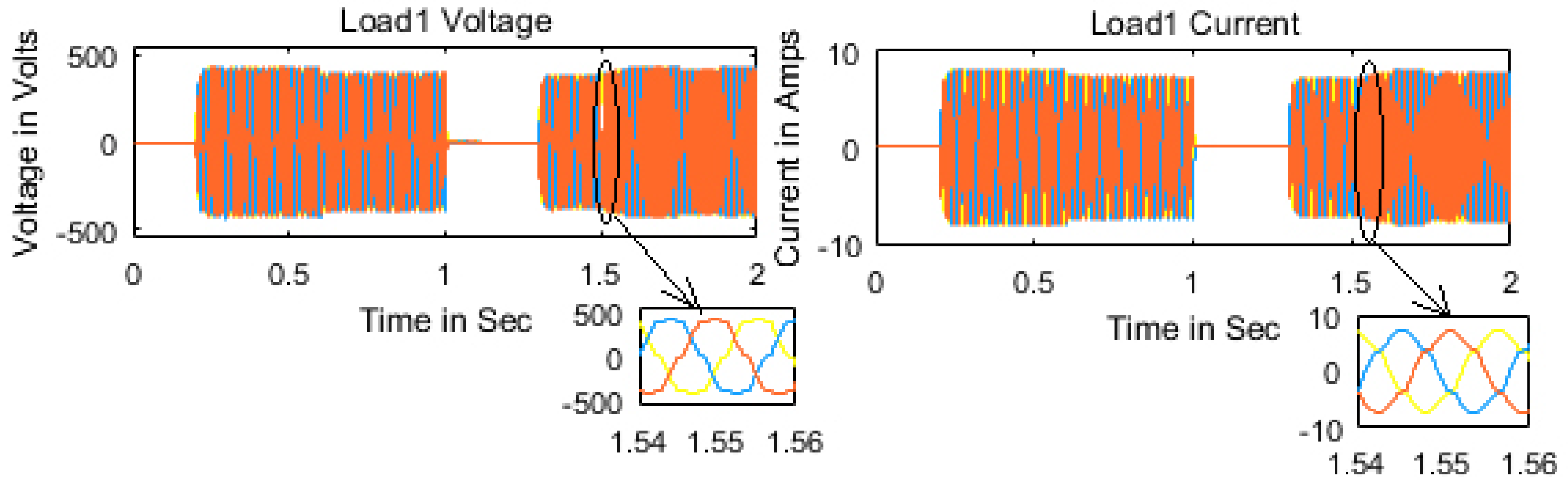
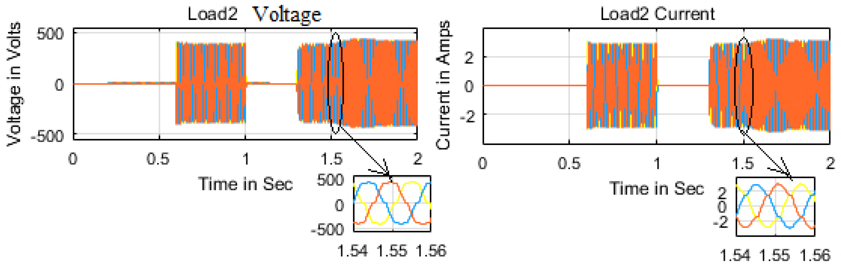
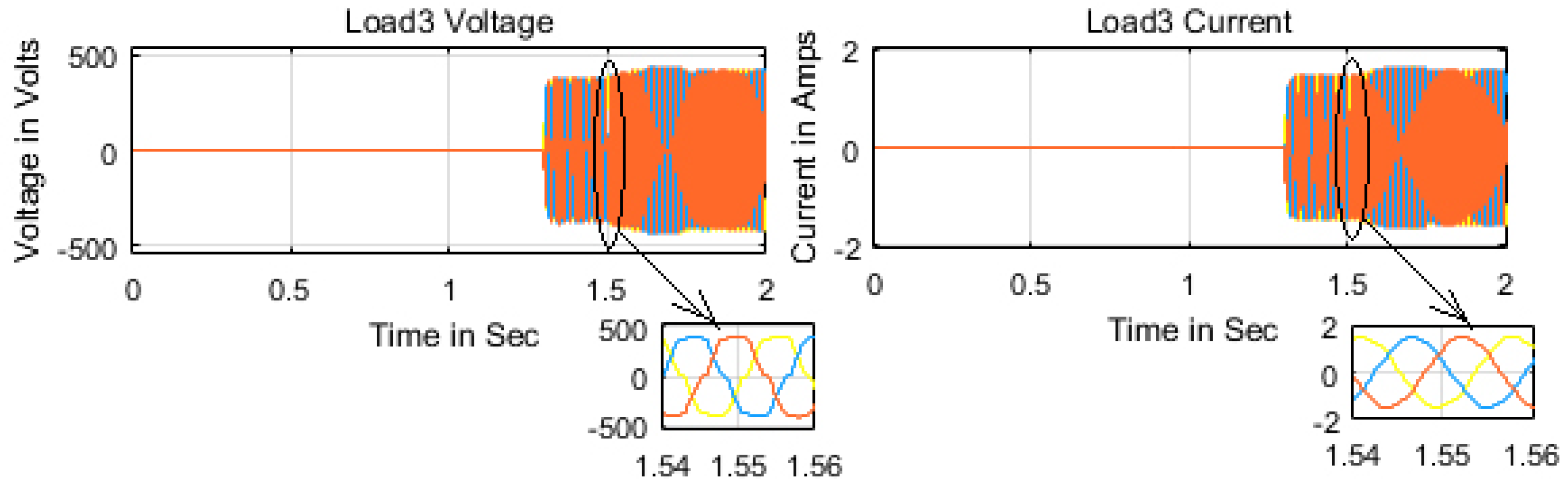
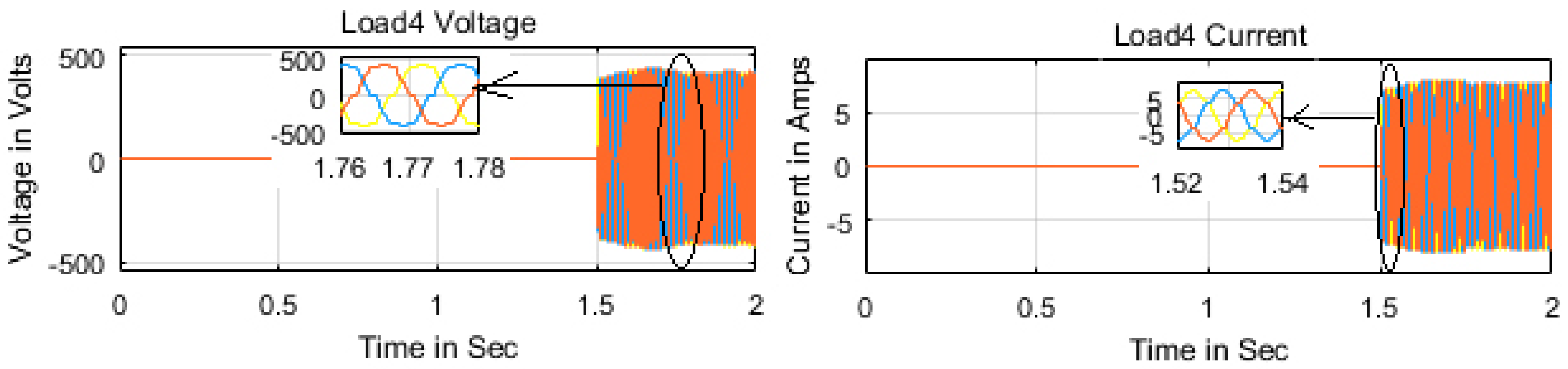
| Loads | Ratings | Connection Time (sec) c-Closed, o-Opened |
|---|---|---|
| Load1 | 5 kW | 0.2(c)-1(o)-1.3(c) |
| Load2 | 2 kW | 0.6(c)-1(o)-1.3(c) |
| Load3 | 1 kW & 500 VAR | 1.3(c) |
| Load4 | 5 kW | 1.5(c) |
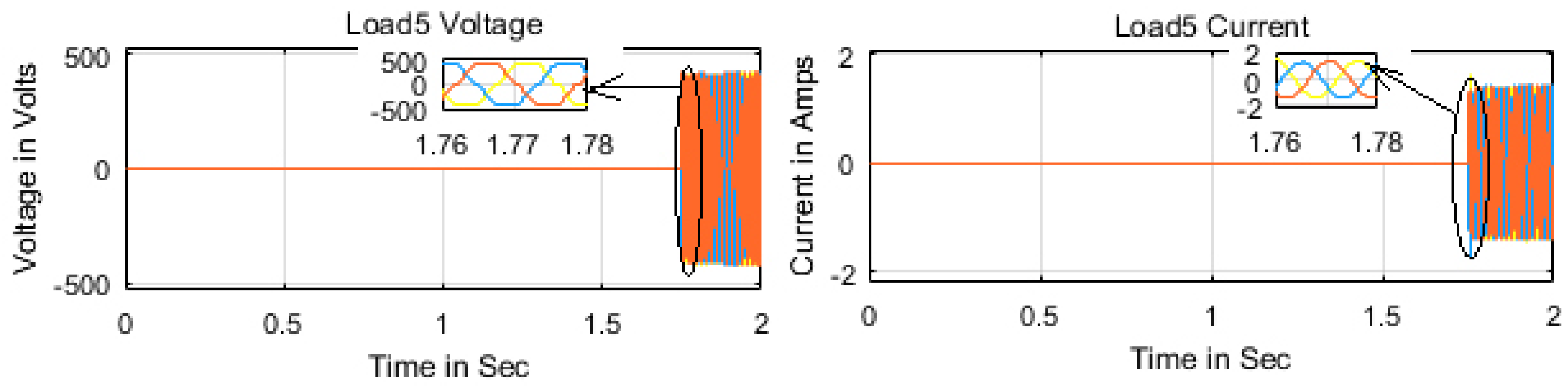
| Load5 | 0.5 kW & 1000 VAR | 1.75(c) |
| Mode | Time in s | Sources |
|---|---|---|
| Autonomous | 0.0–0.5 | Solar |
| 0.5–1.0 | Solar + Wind Generator 1 | |
| 1.0–1.5 | Solar + Wind Generator 1 + Wind Generator 2 | |
| Grid Connected | 1.5–1.75 | Diesel Generator |
| 1.75–2.0 | Diesel Generator + Utility Grid + Battery |
| Mode | Time in s | Sources |
|---|---|---|
| Autonomous | 0.0–0.2 | No sources |
| 0.2–0.6 | Solar | |
| 0.6–1.0 | Solar + Wind Generator 1 | |
| 1.0–1.2 | No sources | |
| 1.2–1.3 | Wind Generator 2 | |
| 1.3–1.5 | Solar + Wind Generator 1 + Wind Generator 2 | |
| Grid Connected | 1.5–1.75 | Diesel Generator |
| 1.75–2.0 | Diesel Generator + Utility Grid + Battery |
© 2020 by the authors. Licensee MDPI, Basel, Switzerland. This article is an open access article distributed under the terms and conditions of the Creative Commons Attribution (CC BY) license (http://creativecommons.org/licenses/by/4.0/).
Share and Cite
Sendraya Perumal, A.; Kamaraj, J. Coordinated Control of Aichi Microgrid for Efficient Power Management Using Novel Set Point Weighting Iterative Learning Controller. Energies 2020, 13, 751. https://doi.org/10.3390/en13030751
Sendraya Perumal A, Kamaraj J. Coordinated Control of Aichi Microgrid for Efficient Power Management Using Novel Set Point Weighting Iterative Learning Controller. Energies. 2020; 13(3):751. https://doi.org/10.3390/en13030751
Chicago/Turabian StyleSendraya Perumal, Angalaeswari, and Jamuna Kamaraj. 2020. "Coordinated Control of Aichi Microgrid for Efficient Power Management Using Novel Set Point Weighting Iterative Learning Controller" Energies 13, no. 3: 751. https://doi.org/10.3390/en13030751
APA StyleSendraya Perumal, A., & Kamaraj, J. (2020). Coordinated Control of Aichi Microgrid for Efficient Power Management Using Novel Set Point Weighting Iterative Learning Controller. Energies, 13(3), 751. https://doi.org/10.3390/en13030751