Abstract
For the safety of the supply, diesel generator (DG) sets are used in various stand-alone power systems using variable-speed generators. The stand-alone hybrid grid system presented in this article, with a wind generator and a diesel generator, but also the system of a ship’s network, serves as an example. To ensure the safety of the ship’s exploitation, the parallel operation of two stand-alone power supplies is required. In parallel operation with the required symmetrical active power load (regardless of the load size), the internal combustion engine of the DG set is often underloaded. This leads to deterioration of its technical properties and, consequently, to a negative impact on the environment. This article presents an analysis of the stand-alone hybrid power system of a ship’s grid consisting of a DG with a speed and voltage regulator and a shaft generator of variable speed—a permanent magnet synchronous generator (PMSG). The possibility of controlling the active and reactive power distribution between the DG and shaft generator (SG) was also studied. Control over the mechatronic SG–DG system limits the harmful influence of the DG on the environment and, most of all, improves the technical qualities of the engine of the DG system, which is often underloaded. Analytic studies of the system were performed, and simulation results of the mechatronic model are presented.
1. Introduction
Hybrid power systems are used in modern power-generating ship grids. They are also widely used in stand-alone power-generating grids with renewable energy sources. To ensure the high quality of electricity and, most of all, the continuity and reliability of the supply, energy-storing systems and stand-alone power-generating systems, such as diesel generators (DGs), are used. Applying DGs in hybrid systems along with other sources of electric power often causes the diesel engine to work for long periods at reduced load. This, in turn, leads to unfavorable phenomena occurring in the engine (called “wet stacking”), which increase the widely understood costs of engine exploitation and unfavorable environmental phenomena. This paper proposes the limitation of the “wet stacking” phenomenon via optimization of the operating mode of power-generating systems on the basis of hybrid systems with synchronous generators used on ships. This article presents the cooperation between the DG (at constant speed) and the electrical generator driven by the main shaft of the ship’s propeller (at variable speed)—a permanent magnet synchronous generator (PMSG). The realized mechatronic system control from the PMSG allows for full control over the distribution of power from the two active and reactive generators. The solution proposed in the article, which was verified by the use of analytical and simulation studies, allows for the limitation of waste, increase of the power supply quality, and, most of all, limitation of unfavorable phenomena occurring in the diesel engine of the DG set.
There has been great progress in the practice of the planning and building of stand-alone power systems thanks to successes in the fields of electromechanics, power electronics, and microprocessor technology development. However, problem analysis shows that in modern power systems, there are still unused reserves for improvement of the power efficiency of mechatronic systems of power conversion.
The improvement of the electromechanical power conversion efficiency on ships can be best ensured by the optimization of the operation modes of power-generating systems. In the systems of marine power plants, DGs are used together with power-generating systems. Turbogenerators (using the exhaust power of the main engine) or shaft generators (where the generator drive comes from the main engine shaft) are used less often. The first trials using shaft generators (SGs) were conducted on ships in the 1980s. The application of SGs was connected mainly to increased economic efficiency [1]. However, the fact that it was not possible to maintain constant voltage and frequency parameters as the shaft speed changed caused partial decommissioning of SGs. Parallel operation of SGs and DGs may have been only short-lasting in order to transfer the load either manually or automatically [2]. In the last several years, thanks to the application of modern power electronic technologies, shaft generators on ships [3] with the possibility of long-term parallel operation of SGs and DGs have been used more often.
When trying to ensure safety during maneuvers and when cruising “difficult” areas (river, canal, straits, lakes, etc.), parallel operation of stand-alone power-generating systems is required in order to ensure a constant power supply, no matter the power demand. In such conditions, the drive engines of DGs are often underloaded (20%–30% of nominal power) [4]. In the conditions presented, the fuel is not burned entirely, which causes exploitative problems in the drive diesel engines of the DG sets. This is when the unfavorable phenomenon called “wet stacking” [5,6] occurs. When the diesel engine is underloaded, overflow of the air supplied for burning appears (the ratio of air to fuel can exceed 500:1). Not all of the injected fuel will be burned, and this can condense, creating carbon deposits on the surface of the engine’s elements [5]. Figure 1 presents the effects of the “wet stacking” phenomenon on a diesel engine’s piston.
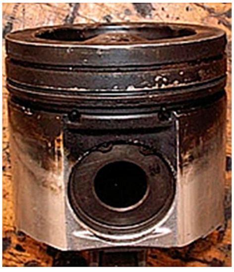
Figure 1.
Effects of the “wet stacking” phenomenon [5].
Partial burning of the oil results in a large relative coefficient of CO2 and greenhouse gases emissions. These gases contribute to air pollution. For instance, the emission of HC, CO, and NOx (g/kWh) is two to three times higher at the 25% engine load than at the 75% load [7].
A common way to reduce this disadvantageous effect in industry (especially in the United States) is to use a load bank [8]. This is most often an automatically controlled resistor, which loads the DG generator unit, converting electrical energy into heat energy. Improving the operating conditions of the diesel engine reduces “wet stacking”, but at the cost of much greater fuel consumption. This solution is becoming difficult to implement in parallel DG–SG work.
One of the possible ways to limit the results of “wet stacking” is temporary asymmetrical operation of the power-generating systems [4]. Such operation can be realized at the parallel connection of the DG and SG. In this operating mode, the engine of the DG system is loaded at 60%–70% of the generator’s nominal value. Asymmetrical operation lasts for a few hours and it raises the temperature of the combustion gases high enough to evaporate the unburned fuel in the exhaust system and to blow the soot. Since the electrical power of the SG constitutes from 0.02 to 0.1 of the main engine power (depending on the ship type), the change in the electrical load does not affect the operation of the main engine.
Figure 2 shows the proposed idea of engine cleaning in a DG set. The parallel work of DG and SG generator sets according to the regulations is symmetrical. If the DG set is underloaded, the diesel engine becomes “dirty” (by, among other things, fouled injectors and a buildup of carbon on the exhaust valves). The idea of diesel engine cleaning is to load about 75% to 100% of the nominal value, raising the temperature of the exhaust gas to evaporate unburned fuel in the exhaust system and blow out the soot via asymmetric operation of the generator sets. The cleaning time is determined by a specialist mechanic (usually 2–3 h).
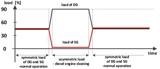
Figure 2.
The idea of cleaning the diesel engine of a diesel generator (DG) set.
This article refers to the power system of a ship grid, in which the SG uses a PMSG. The SG operates at different speeds cooperating with the synchronous generator, while the electric excitation synchronous generator (EESG) of the DG system is at constant speed, generating power for the common load. Using a PMSG (in the SG system) in the stand-alone hybrid ship grid in comparison to applying a classical EESG results in increased performance of the SG system [9]. It must be noted that the performance of the PMSG in relation to other generators, especially for low loads, is much higher [10].
Currently, in the most commonly occurring SG systems, generators with electromagnetic excitation, where a gearbox is necessary (the ship’s main engines are slow-speed engines, and generators with electromagnetic excitation are mid-speed generators), are used. This makes the maintenance costs higher (usually at variable drive speed) and drive performance lower by about 2%, depending on the number of gear stages [9]. Using a slow-speed PMSG (with a direct drive) leads to the elimination of these faults [6,11]. The solution proposed in this article optimizing the work of two different current sources (SG and DG) may possibly also be used on land in so-called stand-alone hybrid electric grids, which assume parallel operation of DGs and WGs (wind generators) [12,13,14,15,16,17,18,19,20,21].
2. Description of the Mechatronic PMSG–EESG System
Figure 3 presents a flowchart of the system. The main system elements include the following:
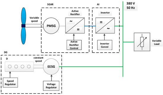
Figure 3.
Flowchart of the ship’s mechatronic system with two generators (permanent magnet synchronous generator (PMSG)–electric excitation synchronous generator (EESG)).
- A diesel generator (DG), which consists of a diesel engine (D) with a speed regulator (SR) and an electric excitation synchronous generator (EESG) with electromagnetic excitation and a voltage regulator (VR);
- A shaft generator (SGAR) that is mechanically connected to the ship’s shaft and consists of:
- -
- a permanent magnet synchronous generator (PMSG); and
- -
- an active rectifier (AR) with a control system (active rectifier control—ARC);
- An autonomous inverter (AI) with a control system (inverter control); and
- An alternating current grid (380 V, 50 Hz) with a variable load (VL).
The voltage at the output of the PMSG changes proportional to its rotary speed.
The active rectifier maintains constant voltage on the DC bus during voltage change at the output of the PMSG, and the inverter maintains constant frequency in the AC grid and enables power control of the two generators.
In the studied power electrical grid of the ship, the electromagnetic and power processes for every possible distribution of power between the generators are examined.
Taking the above into account, the researcher faces the problem of summing up the power of two (sometimes more) sources of accelerating voltage. Summing up the power of energy sources has a long history [22,23]. In cases where the sources are voltage sources, oscillation processes arise, and then the sources exchange energy, omitting the voltage. The problem of summing up the power of two or more sources is much easier if one source is a voltage source (master mode) and the other (or other few) is a current source (slave mode). In such a system, the current source can be easily realized with the use of an autonomous inverter with power control [22,24]. In this case, the voltage at the output of the inverter is controlled with the possibility of amplitude and phase adjustment, which enables the generation of both active and reactive power for the load with full control of this power. During the design of a mechatronic system for autonomous and non-autonomous objects, the optimization of energy characteristics is of great importance. The solution is based on the analysis of electromagnetic processes in the considered systems [25].
2.1. Analysis of the PMSG–AR Mechatronic System
In the block diagram (Figure 3), a part of the mechatronic system, the SGAR, is marked with a dashed line. The analysis of this system was conducted in [26]. It has been pointed out that the voltage value at the AR output is constant over change of the rotation speed of the PMSG and over load change in a given range.
Similar analysis was conducted for the PMSG with the parameters presented in Table 1 [27].

Table 1.
Parameters of the PMSG.
The equivalent circuit of the analyzed PMSG–AR system is presented in Figure 4.
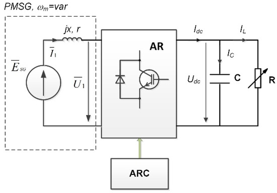
Figure 4.
Equivalent circuit of the PMSG–AR mechatronic system.
A mathematical description of the circuit (Figure 4) from the AC side can be presented as the following relation [28]:
where:
is the EMF vector in the PMSG stator windings;
is the vector of the harmonic fundamental of the voltage generated by the AR;
is the vector of the stator current of the PMSG generator;
r, x are the resistance and reactance of the PMSG stator’s windings; and
is the time derivative.
The SEM value generated in the PMSG in relation to the rotor’s speed and stream can be presented as a relation [26]:
A harmonic fundamental of the voltage generated by the AR can be presented as a relation [26]:
where:
m is the modulation ratio; and
is the phase shift angle between and .
In the synchronously rotating coordinate system d, q, Equations (1)–(3) can be written as [26]:
For a full description of the mechatronic system (Figure 4), Equation (4) should be completed with the energy balance equation and Kirchhoff equation in the DC circuit:
The basic physical properties of the considered system can be specified without solving differential Equations (4) and (5), by considering only working modes in the steady state. In this mode, Equations (4) and (5) are presented in the form of Equations (6) and (7):
The analytical study results are presented in Figure 5 as a relation of the voltage at the output of the AR with change in torque (Te) and rotary speed () of the PMSG.
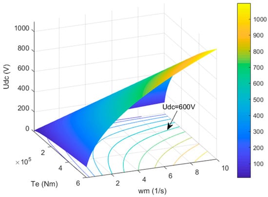
Figure 5.
External characteristics of the PMSG–AR system.
The lines of constant voltage at the output of the AR are the projections of the calculated surface on the plane area. These lines show the relation between the speed and torque of the PMSG when the voltage, Udc, is constant.
The external characteristics of the PMSG–AR system show an acceptable range of change of the generator’s speed and torque when the voltage, Udc, remains at the same level. For Udc = 600 V, the acceptable change of speed is from 3.1 to 10 rad/s and the change of torque is in the range from 600 to 200 kNm.
Hence, at the given ranges for the generator speed and torque change in the PMSG–AR system, for further analysis, we fixed the constant voltage source at Udc = 600 V.
In such a case, the whole SG–EESG system will include elements consisting of a parallelly connected SGAR+AI system and a synchronous generator (EESG).
2.2. Analysis of the SGAR+AI–EESG Mechatronic System
The basis for the analysis of the presented systems is theoretical concepts discussed in publications connected to electrical machine systems together with the semi-conductor converters that control their operation [25,29].
In the discussed works, the study of electromagnetic and power processes was conducted with different degrees of simplification depending on the problems solved. The analysis can be carried out without taking EESG damping windings, aperiodic components of the EESG stator’s currents, or change of the EESG rotary speed into consideration [22].
In the analysis, it is more comfortable to join the coordinate system with the d and q axes of a synchronous machine rotating with synchronous speed [28,30]. The excitation stream vector corresponds to axis d, and the electromotive force vector of the synchronous machine corresponds to axis q. In the design of the autonomous inverter (AI) control circuit for operation with a variable load (VL), control is realized in the synchronously rotating coordinate system (d, q) with negative feedback [28,31].
Electromagnetic processes in the system, taking the above assumptions into account, can be studied on the basis of the equivalent circuit presented in Figure 6.
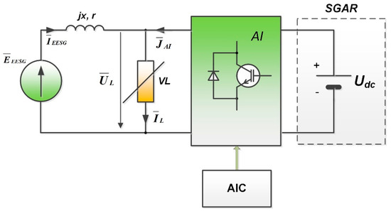
Figure 6.
Equivalent circuit of the EESG–AI–SGAR mechatronic system.
In the circuit presented in Figure 6, the AI is represented as a controlled (AIC) power supply (JAI), which is connected in parallel with the VL and the EESG armature’s windings. The inductive reactance, x, and resistance, r, are internal parameters of the EESG.
A mathematical description of the system in the coordinate system d, q rotating synchronously with the field of the EESG can be presented as:
where:
are the spatial (resultant) vectors of electromotive force on the EESG windings of the DG system in the d and q axes;
are the spatial vectors of voltage on the load VL in the d, q axes;
are the spatial vectors of current of the stator (armature) of the EESG in the d, q axes;
are the spatial vectors of the first harmonic of the current generated by the inverter in the d, q axes;
are the spatial vectors of current in the load in the d, q axes;
are the EESG reactance parameters in the d and q axes; and
r is the resistance of the EESG windings.
It needs to be pointed out that etc. in Equation (8) are highlighted by the fact that these values are fixed with the values variable in time. Changes in the values of currents, voltages, and electromotive force can be observed during transient states.
In a synchronous state, taking the relation r << xd, r << xq [26] into account, the simultaneous Equation (8) will transform to:
A general vector diagram of the system is presented in Figure 7.
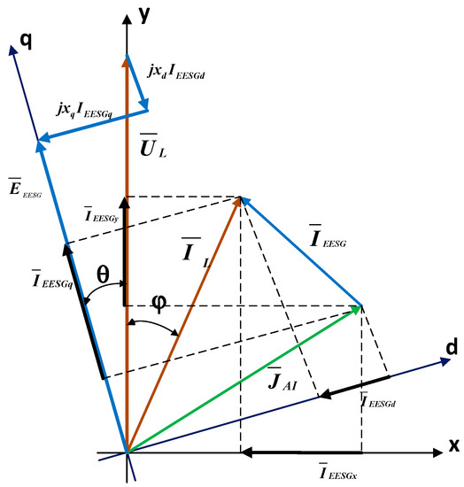
Figure 7.
General vector diagram of the EESG mechatronic system with SGAR+AI.
The presence of a controlled (amplitude and phase) source of current (realized by the inverter) allows for adjusting both some active and reactive current from 0% to 100% IL in the SGAR+AI system, and simultaneously adjusting both the active and reactive power output from the EESG.
Both the active and reactive current of the load are defined by known equations with the coordinates x, y:
The EESG currents in the x, y axes result from the equation:
The presence of an active component in the EESG armature current lends a change in the electromotive force of the generator and shifts the EESG d, q coordinate system with respect to the coordinates x, y connected to the load by the load angle.
On the basis of vector diagrams, geometrical counterparts of the time variables can be used. The EESG currents in axes d, q on the vector diagram are defined according to the Park–Gorev transformation [28,31]:
Geometrical relations in the vector diagram taking Equation (6) into account allow us to calculate the angle of the load:
The EESG electromotive force in axes d, q in the vector diagram can be determined by the equation:
Voltage on the load, UL, in axles d, q in the vector diagram can be determined by the equation:
Geometrical relations in the vector diagram allow us to calculate the power supplied by the synchronous generator and shaft generator (inverter) depending on the parameters of the load and the preset current of the inverter. These powers are determined on the basis of these equations:
where PL, QL are the active and reactive power of the load, PEESG, QEESG are the EESG active and reactive power, and PAI, QAI are the SGAR+AI (generated from the AI) active and reactive power.
The preset currents of the inverter can have any value, depending on the range. Further currents in the analysis are set according to the equation:
where k can change from 0 to 1.
The physics of the work of the two generators for one load were analyzed with the use of vector analysis based on Equations (2)–(5), (9), and (10). As an example, we took the equality of loads on the generator of the DG and SGAR–AI system. We took a closer look at three cases: A case with equal distribution of both the active and reactive power of the load into the EESG and SGAR+AI, a case when all the active power is realized by SGAR+AI and all reactive by the EESG, and a case when all active power is realized in the EESG and all reactive power is realized in SGAR+AI.
Below, in the analysis of currents, the setpoints of the currents are in line with Equation (9):
- (a)
- In the case of equal distribution of both the active and reactive power of the load into the DG and SGAR+AI, the relation between the currents of the load of the generator and current source (AI) in the synchronously rotating coordinate system d, q takes the form:Figure 8 presents a vector diagram for this case.
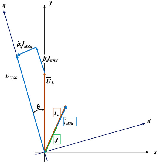 Figure 8. A general vector diagram of the EESG mechatronic system with SGAR+AI.
 - (b)
- In the case when all active power is realized by SGAR+AI (active power generated by the inverter) and all reactive by the EESG, the relation between the currents of the generator load and current source (AI) in the synchronously rotating coordinate system d, q takes the form:Figure 9a presents a vector diagram for this case.
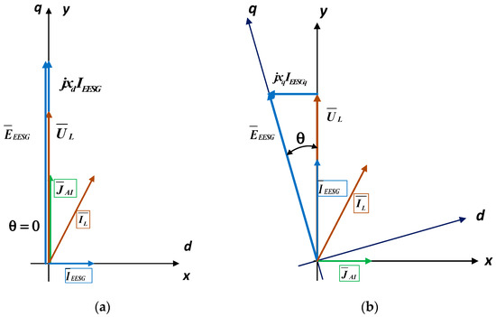 Figure 9. (a) Vector diagram for the case of taking the whole load of active power by SGAR+AI and all reactive power by EESG. (b) Vector diagram for the case of taking the whole load of active power through the EESG and all reactive power through SGAR+AI.
 - (c)
- In the case when all active power is realized in the EESG and all reactive power is realized in SGAR+AI (generated by the inverter), the relation between the currents of the load of the generator and current source (AI) in the synchronously rotating coordinate system d, q takes the form:
Figure 9b presents a vector diagram for this case.
Figure 10 and Figure 11 present the calculated powers realized in the EESG and SGAR+AI when the load current and its phase change depend on three values, which relates to two examples:
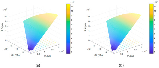
Figure 10.
(a) Active power diagram in the EESG for k = 0.5. (b) Active power diagram in SGAR+AI for k = 0.5.
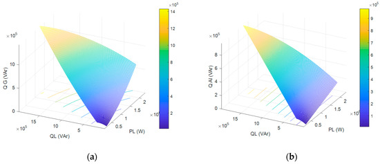
Figure 11.
(a) Reactive power diagram in the EESG for k = 0.5. (b) Reactive power diagram in SGAR+AI for k = 0.5.
- k = 0.5 for (JAIx = 0.5ILx, JAIy = 0.5ILy);
- k = 0 for (JAIx = 0, JAIy = ILy); and
- k = 1.0 for (JAix = ILx, JAIy = 0).
These relations are realized by spatial coordinates (3D), which allow us to calculate the energy properties of the whole system.
Figure 9 and Figure 10 relate to the example in which both the active and reactive power of the load are evenly distributed between the EESG and SGAR+AI (k = 0.5). The projections of the calculated areas on the main plane are lines of equal power. Using these curves, with a known load current and its phase in relation to voltage, both the active and reactive power taken from the EESG and inverter are defined.
Figure 12 and Figure 13 present an example in which all reactive power is taken from SGAR+AI (generated by the inverter). In this case, all active power is taken from the generator of the DG system (k = 1).
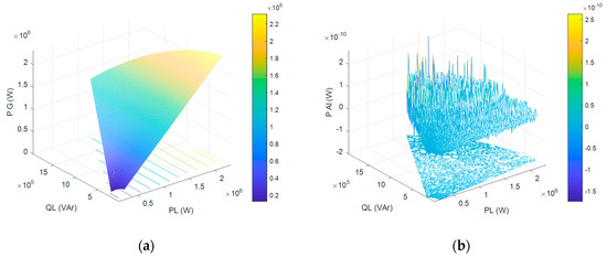
Figure 12.
(a) Active power diagram in the EESG for k = 1. (b) Active power diagram in SGAR+AI for k = 1.
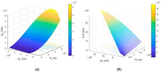
Figure 13.
(a) Reactive power diagram in the EESG for k = 1. (b) Reactive power diagram in SGAR+AI for k = 1.
It needs to be pointed out that the areas and their projections assigned in Figure 11, Figure 12 and Figure 13 allow us to determine the acceptable range of load parameter change while maintaining constant proper power.
3. Implementation of the Proposed DG–SG System
In order to check the above analysis, we undertook simulation studies of the system with a synchronous, salient-pole generator with electromagnetic excitation of the DG system. The parameters of the EESG generator of the DG power-generating system are presented in Table 2. The PMSG parameters of the SG are presented in Table 1.
Table 2.
Parameters of the EESG.
The load parameters were as follows: PL = 2000 kW, QL = 1000 kVAr.
The simulation results are presented with the use of the following designations: UL, IL are the voltage and current of the load, UEESG, IEESG are the voltage and current of the EESG generator, and UAI, IAI are the voltage and current of the AI (SG).
Figure 14 presents the simulation model of the stand-alone hybrid system of a ship SG–DG power plant.
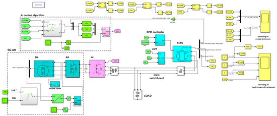
Figure 14.
Simulation model of a stand-alone hybrid ship power plant system with parallel operation of an DG and SG.
Figure 15 shows the developed control block (from Figure 14), which generates a signal for the AI in order to distribute active and reactive power in the system. The reactive current determined from the load’s reactive power (Q_Load) and the load’s voltage (UL) in accordance with the given k factor determines the current of the d component (Id*). The active current determined from the load’s active power (P_Load) and the load voltage (UL) according to a given k factor determines the current of the q component (Iq*). After converting the Idq0* currents into the set values of Iabc* currents and comparing the hysteresis block with the actual values of Iabc, the AI control signal is generated.
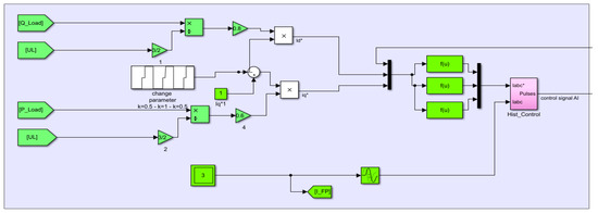
Figure 15.
Simulation model of the AI control block.
Figure 16 shows the developed control block (from Figure 14), which develops a signal for the AR in order to maintain constant voltage of the AR–AI converter’s DC circuit. The PID controller develops the Iq* current setpoint value by comparing the DC circuit voltage with the setpoint voltage. Here, Id* = 0 and I0 = 0. After converting the Idq0 currents into the set values of Iabc* currents and comparing the hysteresis block with the actual values of Iabc, the control signal AR is generated.
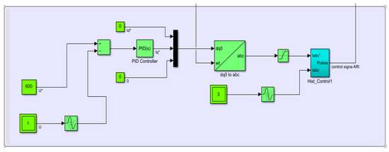
Figure 16.
Simulation model of the AR control block.
4. Results and Discussion
Figure 17 presents the energy processes in the system during changes in the AI control currents.
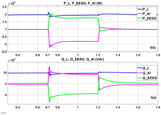
Figure 17.
Energy processes during the operation of the mechatronic DG–SG system during a change from k = 0.5 to k = 1 (“cleaning” of the diesel engine of the DG set) and then back to k = 0.5.
In the first time interval (up to about 0.7 s in Figure 17), both active and reactive power are evenly distributed between the two power-generating systems, DG and SG (k = 0.5).
The operation of the systems in this case is long lasting. When a DG power-generating system is underloaded, this operation results in the occurrence of unfavorable phenomena in the diesel driving engine (“wet stacking”). In the second time interval (from about 0.7 s up to about 1.2 s in Figure 17), both active and reactive power are asymmetrically distributed between the generators (k = 1). Almost all active power of the PL load falls on the DG system (PEESG). The diesel engine of the DG power-generating system is then “cleaned”. In order to limit losses, the QL reactive power is taken over by the SG power-generating system (QAI).
The asymmetrical operation time takes about 2 to 3 h depending on the diesel engine operating time at underloading and the engine’s load at this time. In the third time interval (from 1.2 s in Figure 17), there is a shift back to symmetrical loading of the power-generating systems. The power transition processes are close to periodic processes.
Figure 18 shows the energy processes during AI control at the transition from symmetrical operation (factor k = 0.5) to asymmetrical operation (factor k = 0). During this operation mode (k = 0), the DG unit is only loaded with reactive power. The fuel consumption is minimal (diesel engine idling). All the active power is supplied by the SG system.
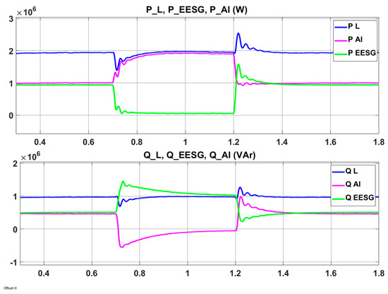
Figure 18.
Energy processes in the operation of the mechatronic DG–SG system during a change from k = 0.5 to k = 0 (minimum fuel consumption of the diesel engine of the DG set) and then back to k = 0.5.
In system operation mode k = 0, fuel consumption is minimal, but this mode is not acceptable due to the intensity of the negative effects of “wet stacking” in the generator’s engine.
Figure 19 presents the electromagnetic processes during the operation of the DG–SG system at the described switchovers. The voltage on the rails of the UL main switchboard in the steady state remains at the same level (phase voltage UL of 230 V is maintained). The transition processes of voltages and currents depend on the DG speed controller parameters (RPM controller, Figure 14), EESG voltage controller (AVR, Figure 14), and AI controller parameters (AI control algorithm, Figure 14).
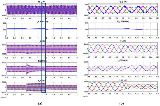
Figure 19.
Electromagnetic processes in the operation of the DG–SG mechatronic system during (a) change from k = 0.5 to k = 1 and then back to k = 0.5; (b) in the interval of time 1.15–1.25 s changing from k = 1 to k = 0.5.
The synthesis of the parameters of the controllers discussed presents an issue to be solved in future scientific studies.
The results of the simulation studies confirm the ability of the system to distribute both active and reactive power of the load in any way in relation to the defined AI control signals. The redistribution of power takes place without the oscillatory processes of active and reactive power exchange between generators and a load.
5. Conclusions
The specifics of using power-generating systems on a ship often require their parallel operation. This requirement results not only from the need for electricity but also, and above all, from the necessity to provide for the ship’s safety, especially in difficult sailing conditions or maneuvers. Parallel operation in such conditions often causes long-term operation of the diesel engine of DG generating systems at underload and, as a consequence, results in the unfavorable phenomenon of “wet stacking”.
“Wet stacking” is a condition in diesel engines in which unburned fuel (hydrocarbons) passes into the exhaust system. In diesel generators, this usually happens because the diesel engine only works at a small percentage of its rated power. To ensure efficient combustion, the diesel engine should run at a minimum of 60% of the rated output power. In addition, operating at low temperatures or other situations that prevent the engine from reaching an appropriate operating temperature can cause fuel to accumulate due to incomplete combustion, which can lead to "moisture accumulation". This engine condition also has negative effects on the emission of harmful exhaust components, including carbon monoxide (CO), hydrocarbons (HC), and nitrogen oxides (NOx). As research shows, engine underload causes a several-fold increase in the emissions of these exhaust components compared to the emissions of a properly loaded engine. The asymmetric parallel operation of generators proposed in this article increases the energy efficiency of the combined system but also significantly reduces the emission of harmful exhaust components to the environment and increases the durability and reliability of the engine used in the system. The asymmetric mode, k = 0, is not recommended as it leads to a greater intensity of negative “wet stacking” effects in the combustion engine.
The asymmetrical work is done in such a way that one generator (of the DG system) is loaded at 80%–90%, and the other one (SG) is at 10%–20% of the total power of load. This allows for “cleaning” of the diesel engine of the DG system.
The mathematical description of the mechatronic system with two generators (PMSG and EESG) working in a common stand-alone grid and the studies carried out on the model presented in this article allowed us to analyze all possible cases of redistribution of the power of the two generators, in both steady and transitional modes of work.
The proposed solution discussed on the basis of a ship electrical power grid can also be used in stand-alone hybrid on-land grids where parallel wind generator (a variable-speed PMSG) and DG operation is applied.
Author Contributions
Conceptualization, S.G.-G., D.T., Z.M. and M.J.; Formal analysis, S.G.-G. and D.T.; Investigation, S.G.-G. and D.T.; Methodology, S.G.-G. and D.T.; Resources, S.G.-G., D.T., Z.M. and M.J.; Software, S.G.-G. and D.T.; Supervision, S.G.-G., D.T., Z.M. and M.J.; Validation, S.G.-G.., D.T., Z.M. and M.J.; Visualization, S.G.-G. and D.T.; Writing—original draft, S.G.-G. and D.T.; Writing—review & editing, S.G.-G., D.T., Z.M. and M.J. All authors have read and agreed to the published version of the manuscript.
Funding
This research received no external funding.
Conflicts of Interest
The authors declare no conflict of interest.
References
- Nicewicz, G.; Tarnapowicz, D. Conceptions of Shaft Generators Use in Up-to-Date Marine Power Plants. Stud. Proc. Polish Assoc. Knowl. Manag. 2011, 40, 283–294. [Google Scholar]
- PRS Classification Rules Part VIII. In Electrical Installations and Control Systems; PRS: Gdańsk, Poland, 2007.
- Tarnapowicz, D. The conception of the use of multi-level inverters in the shipping shaft generator systems of high power. Sci. J. Marit. Univ. Szczec. 2010, 22, 67–70. [Google Scholar]
- Tarnapowicz, D. Load Analysis of a Ship Generating Sets During the Maneuvers of the Vessel. In Proceedings of the 59th International Conference of Machine Design Departments, Demanovska Dolina, Slovakia, 11–14 September 2018. [Google Scholar]
- Wright, G. Fundamentals of Medium/Heavy Duty Diesel Engines; Jones & Bartlett: Burlington, MA, USA, 2015; p. 234. [Google Scholar]
- Semken, R.S.; Polikarpova, M.; Röyttä, P.; Alexandrova, J.; Pyrhönen, J.; Nerg, J.; Mikkola, A.; Backman, J. Direct-Drive Permanent Magnet Generators for High-power Wind Turbines: Benefits and Limiting Factors; Renewable Power Generation; IET: London, UK, 2012; Volume 6, pp. 1–8. [Google Scholar]
- Kristenen, H.O. Energy Demand and Exhaust Gas Emissions of Marine Engines; Psaraftis, H., Ed.; Project no. 2014-122: Mitigating and Reversing the Side-Effects of Environmental Legislation on Ro-Ro Shipping in Northern Europe Work Package 2.3, Report no. 03 2015; The Technical University of Denmark: Kopenhaga, Denmark, 2015; Available online: https://www.danishshipping.dk/ (accessed on 29 November 2019).
- ASCO Power Technologies. Adverse Effects of Low Load Operation on Diesel Generating Sets. Available online: Whitepapers.ascopower.com (accessed on 1 November 2019).
- German-Galkin, S.; Tarnapowicz, D.; Tomasov, S. The Use of Topology of IHBI Inverters in Parallel Operation of Ship Generating Sets with PMSG Generators Published Online in New Trends in Production Engineering; De Gruyter Poland: Warsaw, Poland, 2018; Volume 1, pp. 309–315. [Google Scholar] [CrossRef]
- Jamieson, P. Innovation in Wind Turbine Design, 1st ed.; A John Wiley & Sons, Ltd.: Hoboken, NJ, USA, 2011. [Google Scholar]
- López-Ortiz, E.N.; Campos-Gaona, D.; Moreno-Goytia, E.L. Modelling of a wind turbine with permanent magnet synchronous generator. In Proceedings of the IEEE 2012 North American Power Symposium (NAPS), Champaign, IL, USA, 9–11 September 2012. [Google Scholar]
- Kostin, V.N.; Belsky, A.A. Wind and Diesel Paralleled Generators Characteristics of Operating Parameters. In Proceedings of the 2016 2nd International Conference on Industrial Engineering, Applcations and Manufacturing (ICIEAM), Chelyabinsk, Russia, 19–20 May 2016; ISBN 978-1-5090-1322-7. [Google Scholar]
- Moon, H.; Kim, Y.J.; Chang, J.W.; Moon, S. Decentralised Active Power Control Strategy for Real-Time Power Balance in an Isolated Microgrid with an Energy Storage System and Diesel Generators. Energies 2019, 12, 511. [Google Scholar] [CrossRef]
- Hamilton, J.M.; Negnevitsky, M.; Wang, X.; Tavakoli, A. Investigation of no load diesel technology in isolated power systems. In Proceedings of the IEEE Power and Energy Society General Meeting (PESGM), Boston, MA, USA, 17–21 July 2016. [Google Scholar]
- Guo, L.; Liu, W.; Li, X.; Liu, Y.; Jiao, B.; Wang, B.; Wang, C.; Li, F. Energy management system for stand-alone wind-powered-desalination microgrid. IEEE Trans. Smart Grid 2016, 7, 1079–1087. [Google Scholar] [CrossRef]
- Hasanien, H.M.; Muyeen, S.M.; Tamura, J. Frequency Control of Isolated Network with Wind and Diesel Generators by Using Fuzzy Logic Controller. In Proceedings of the International Conference on Electrical Machines and Systems, Tokyo, Japan, 15–18 November 2009. [Google Scholar]
- Gado, A.; Okasha, H.; Salama, G. Optimizing alternative backup power supplies with wind generator to supply isolated loads. In Proceedings of the 22nd International Conference and Exhibition on Electricity Distribution (CIRED 2013), Stockholm, Sweden, 10–13 June 2013; ISBN 978-1-84919-732-8. [Google Scholar]
- Sujith, S.; Ramesh, V. Reducing the transient active power from diesel generator using flywheel energy storage system in isolated wind-diesel hybrid power system. In Proceedings of the 2015 International Conference on Power, Instrumentation, Control and Computing (PICC), Thrissur, India, 9–11 December 2015. [Google Scholar]
- Hamilton, J.M.; Negnevitsky, M.; Wang, X.; Tavakoli, A.; Mueller-Stoffels, M. Utilization and Optimization of Diesel Generation for Maximum Renewable Energy Integration. In Smart Energy Grid Design for Island Countries; Green Energy and Technology; Springer: Cham, Switzerland, 2017. [Google Scholar] [CrossRef]
- Ochoa, D.; Martinez, S. Proposals for Enhancing Frequency Control in Weak and Isolated Power Systems: Application to the Wind-Diesel Power System of San Cristobal Island-Ecuador. Energies 2018, 11, 910. [Google Scholar] [CrossRef]
- Lu, J.; Wang, W.; Zhang, Y. Multi-Objective Optimal Design of Stand-Alone Hybrid Energy System Using Entropy Weight Method Based on HOMER. Energies 2017, 10, 1664. [Google Scholar] [CrossRef]
- Tokarev, L.N. Mathematical Description, Calculation and Modeling of Physical Processes in Ship Power Plants; Sudostroenie: Leningrad, Russia, 1980; p. 119. [Google Scholar]
- Yasakov, G.S. Ship Electric Power Systems. Part 1—S.-Pb; N. G. Kuznetsov Naval Academy: Saint Petersburg, Russia, 1999; p. 640. [Google Scholar]
- Tarnapowicz, D.; German-Galkin, S. Energy optimization of mechatronic systems with PMSG. In Proceedings of the 3rd International Conference on Energy and Environmental Protection, Kraków, Poland, 13–14 September 2018; Volume 46, pp. 1–8. [Google Scholar] [CrossRef]
- German-Galkin, S. Matlab and Simulink; Designing Mechatronic Systems on a PC. St.; KORONA-Vek: Petersburg, Russia, 2008; pp. 220–228. ISBN 978-5-903383-39-9. [Google Scholar]
- German-Galkin, S. MATLAB School: Lesson 24. In Mechatronic System with Magnetoelectric Generator and Active Semiconductor Rectifier; Magazine “Power Electronics” No.1(70); Power-e: St-Petersburg, Russia, 2018; pp. 65–72. [Google Scholar]
- Wu, B.; Lang, Y.; Zargari, N.; Kouro, S. Power Conversion and Control of Wind Energy Systems; John & Sons, Inc.: Hoboken, NJ, USA, 2011; ISBN 9780470593653. [Google Scholar]
- Park, R.H. Two-Reaction Theory of Synchronous Machines—II; IEEE: New York, NY, USA, 1933; Volume 52, Available online: https://ieeexplore.ieee.org/ (accessed on 29 November 2019). [CrossRef]
- Bulgakov, A.A. New Theory of Controlled Rectifiers; Science: Moscow, Russian, 1970; p. Il. [Google Scholar]
- Kovacs, K.P.; Racz, I. Transient Processes in Alternating Current Machines; Transiente Vorgänge in Wechselstrommaschinen; Verlag der Ungar.: Budapest, Hungary, 1959. [Google Scholar]
- Gorev, A. Transient Processes of Synchronous Machine; State Energy Publishing House (Gosenergoizdat): Leningrad, Russia, 1950. [Google Scholar]


© 2020 by the authors. Licensee MDPI, Basel, Switzerland. This article is an open access article distributed under the terms and conditions of the Creative Commons Attribution (CC BY) license (http://creativecommons.org/licenses/by/4.0/).