Abstract
The working fluid selection is one of the most important issues faced when designing Organic Rankine Cycle (ORC) systems. The choice of working fluid is dictated by different criteria. The most important of them are safety of use, impact on the environment, and physical and chemical parameters. The type of ORC system in which the working fluid is to be used and the type of expander applied in this system is also affecting the working fluid selection. Nowadays, volumetric expanders are increasingly used in ORC systems. In the case of volumetric expanders, in addition to the aforementioned working fluid selection criteria, additional parameters are considered during the selecting of the working fluid, such as the range of operating pressures and geometric dimensions (determining the volume of working chambers) affecting the achieved power and efficiency of the expander. This article presents a method of selecting a working medium for ORC systems using volumetric expanders. This method is based on the dimensionless rating parameters applied for the comparative analysis of different working fluids. Dimensionless parameters were defined for selected thermal properties of the working fluids, namely thermal capacity, mean temperature of evaporation, mean temperature of condensation, pressure and volumetric expansion ratio, volumetric expandability, as well as the heat of preheating, vaporization, superheating, cooling, and liquefaction. Moreover, isentropic expansion work was considered as the rating parameter. In this article, in addition to the working fluid selection method, computational examples related to the selection of the working fluid for the ORC system fed by a heat source featuring specified temperatures are presented. The results of calculations of rating parameters and their comparison gave an outlook on the selection of appropriate working fluids.
1. Introduction
The most important design and scientific problems connected with the Organic Rankine Cycle (ORC) systems design are suitable working fluid and expander selection [1]. Currently, there are many applicable working fluids available. An expander is often selected based on system power and its application. Two types of expansion machines (i.e., turbo and volumetric expanders) can be applied nowadays in ORC systems.
Turbo expanders are mainly applied in large power (1 MW and more) ORC systems harvesting the energy from the heat sources that have high thermal power and temperature (150 °C and more). Such heat sources (e.g., waste heat) are generated in large industrial power machinery, such as steam boilers (e.g., waste steam) or gas turbines (e.g., exhaust gases). In large power ORC systems, silicone oils (e.g., MM (hexamethyldisiloxane) or MDM (octamethyltrisoloxane)) are mainly adopted as working fluids [2].
Volumetric expanders are applied mainly in micro and low-power ORC systems, such as domestic and agriculture plants powered by the heat sources with small capacities, thermal power, and temperature (up to 150 °C) [3]. Low thermal parameters of the heat source also influence the working fluid selection. Only low-boiling working fluids are possible for application in this case. Such working fluids are refrigerants, their mixtures, and similar substances, for example, classically applied R123 and R245fa, as well as new-specially designed fluids, such as R1234yf, R1234ze, or SES36.
Volumetric expanders are a good option for systems in which low pressures and low working medium flows are expected [4]. From many types of the volumetric expanders piston, linear piston, screw, scroll, vane, and rotary lobe expanders are currently applied in ORC plants [5,6,7,8,9,10,11,12,13,14,15,16,17,18,19,20,21]. Volumetric expanders are often characterized by two important parameters, i.e., pressure expansion ratio (the parameter defined as the value of the working fluid pressure at the inlet to the expander in respect to the value of the working fluid pressure at the outlet of the expander—σP = pin/pout) and volumetric expansion ratio (the parameter defined as the value of the working fluid specific volume at the inlet to the expander in respect to the value of the working fluid specific volume at the outlet of the expander—σVEX = v1/v2). Piston expanders are a good option for ORC systems where high (up to 20 MPa in the case of the single stage expanders) inlet pressures of the working fluid are expected, as these machines feature the highest pressure expansion ratios. Piston expanders can be used in ORC systems powered by heat sources featuring fixed characteristics of temperature and thermal power output because it is advisable for these expanders to operate in dry vapor conditions (vapor quality equal to 1) in order to avoid the presence of liquid droplets in the cylinder. Screw expanders can be applied in systems utilizing the heat sources featuring floating temperature, thermal power, and output characteristic because in this type of the expanders, wet gas can be expanded without serious problems. The pressure expansion ratio of a screw expander typically ranges between 10 and 15. Scroll expanders are applied in many ORC systems. The pressure expansion ratio of a scroll expander typically ranges between 2 and 4.5. Multi-vane expanders are currently under development or during the phase of testing the prototypes. Therefore, they are applied mainly in ORC test-stands. Their design is compact, they can operate in wet gas conditions, and are relatively cheap. The pressure expansion ratio of the rotary multi-vane expanders typically ranges between five and seven. Rotary lobe expanders are also under research and development. These expanders are promising because of their advantages, such as insensibility to wet gas conditions, low operating pressures, and simple design. It is suspected that the maximum value of the pressure expansion ratio of a rotary lobe expander will reach the value of σP = 6. The range of working pressures, maximum (σPmax), and typical (σPt) pressure expansion ratios of different types of volumetric expanders are presented in Table 1.

Table 1.
Range of the working pressures, maximum, and typical pressure expansion ratios of different types of volumetric machines [13,14,15].
In the case of volumetric expanders, the obtained output power is dependent on the volumetric and pressure expansion ratio. This is one of the characteristic features of volumetric machinery. This issue was treated in more detail in [3]. Each type of volumetric expander also features the optimum range of the pressure expansion ratio. It is worth noting here that research and development works on novel variable expansion ratio volumetric expanders are ongoing. The examples are scroll machines with injection ports [22,23,24], piston devices with controlled valves [25], and screw machines with sliding ports [26,27,28]. In contrast to turbo expanders, volumetric machines are able to operate under poor operating conditions (i.e., low working fluid flow rates and low pressures). The working fluid selection for ORC systems employing a volumetric expander should, therefore, be considered differently than in the case of the turbine-based ORC systems.
2. Thermodynamic Properties of Working Fluids Suitable for Application in ORC Systems Employing Volumetric Expanders
As indicated in the introduction, volumetric expanders are a good option for ORC systems supplied by low temperature (ca. 150 °C) heat sources. What is more, each type of volumetric expander feature specified the range of the pressure expansion ratio. For this reason, only selected working fluids can be applied in ORC systems employing a volumetric expander. The examples of working fluids that can be used in a low-power ORC system employing a volumetric expander are listed in Table 2 together with their basic thermal properties, which were obtained using REFPROP [28] and CoolProp [29] computer software. The working fluid class (according to the novel classification of working fluids which was proposed in [30]) and reference to the equation of state is also listed in this table for all of the working fluids. It should be mentioned here that R113, R114, R123, R124, R141b, R142b are phased out of use due to their high ODP (Ozone Depletion Potential). However, these substances are treated in the present study as the examples that can be used for further comparative analysis of other working fluids (i.e., those having similar physical properties to phased out ones).
Table 2.
The working fluids suitable for small- and low-power Organic Rankine Cycle (ORC) systems with volumetric expanders [28,29,30].
Working fluids can be described by well-known thermodynamic relations and parameters (e.g., equations of state, specific heat, heat of a phase change, or the thermodynamic functions). Additionally, different parameters can be defined for their description and analysis of applicability to specified conditions. The above-mentioned thermodynamic relations are presented in the form of algebraic or differential equations, tables, graphs, software, etc. Completeness of these data in the case of the substances listed in Table 2, is very different, which does not facilitate the thermodynamic analyses. Figure 1 shows the T–s diagram for a low-boiling substance. The characteristic values of working fluid thermal properties are marked on this graph together with the ambient parameters. The different phases of the working fluid can, therefore, be highlighted, i.e., superheated vapor, moist vapor, and a liquid. Moreover, the area of the critical point (Cr), dry saturated vapor line (x = 1), boiling liquid line (x = 0), and pinch point (ΔTpp) can be marked. Working fluid pressure p(Ta) at ambient temperature (Ta) typically differs from the ambient pressure (pa). The temperature of working fluid evaporation (Tev) at ambient pressure (pa) is one of the basic quantities describing the working fluid, just like the heat of condensation qc(pa) (see isobar-isotherm e–f in Figure 1). The critical point parameters (pcr, Tcr) are other key parameters describing the working fluid. The value of critical pressure (pcr) is a very important parameter defining the operating range of the power plant and organization of the cycle. The critical temperature (Tcr) determines the usefulness of a working fluid to be applied as a heat transfer fluid in a power plant. If Tc < Ta, it would not be possible to liquefy the vapor and pump the liquid, which are the basic processes of a vapor power plant operation. In the T–s graph, which is presented in Figure 1, the power plant cycle (see red lines in Figure 1) and heat source cooling process (see navy blue line in Figure 1) were also visualized.
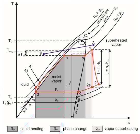
Figure 1.
T–s diagram of a low-boiling working fluid.
Depending on the working fluid type, the saturation curve can have a different shape. Figure 2 shows a comparison of the saturation curves for selected low-boiling working fluids.
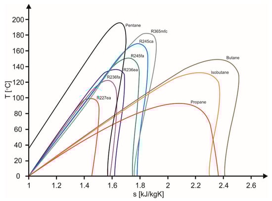
Figure 2.
Saturation curves of different low-boiling working fluids.
3. The Method of Working Fluid Selection
The working fluid selection may be proceeded in many different ways depending on the accepted selection criteria. Different methods of working fluid selection are consciously developed and described in scientific papers, see [46,47,48,49,50,51,52,53,54]. Nowadays, environment protection is an important issue; therefore, many working fluids that were successfully applied in ORCs are being withdrawn (e.g., R11, R12, and others). The environmental impact of the working fluid should be considered during the assessment of the working fluid candidates. The thermal stability of the substance is also of great importance during the working fluid selection [54,55]. However, to fit the working fluid to the ORC, the system selection should be based mainly on the thermal properties of the working fluid [3,56,57]. What is more, the thermal properties of the working fluid should be analyzed together with the heat source characteristics. The thermal power of a heat source that is feeding the ORC system, physical state and type (e.g., gas, liquid), and physical parameters (e.g., density, viscosity, specific heat capacity) of the heat source’s working fluid (e.g., waste heat carrier) have a significant influence on the process of the heat supply to the ORC system. Therefore, the shape of a curve marked as 1–2, which is visualized in Figure 3, may have a different course. For this reason, in addition to the analysis of phenomena that are occurring inside the ORC system (i.e., on low-boiling working fluid side), it is also important to analyze the phenomena that are occurring on the heat source side (i.e., related to heat source’s working fluid). These problems are treated in further discussion. The starting point can be, for example, the course of the heat source cooling process. The heat source cooling process is usually isobaric; however, the course and rate of cooling can be different, and it depends on many different thermal properties of the heat source and working fluid (e.g., heat source temperature, heat capacity of the heat source, specific heat capacity of the working fluid, working fluid mass flow rate, number of heat receivers, etc.). Therefore, the different amounts of heat can be extracted from the heat source at different ranges of the temperature (this process is visualized in Figure 3). These amounts of heat can be presented graphically in a bar chart forming the heat source histogram (see Figure 4). Depending on the course and rate of the cooling process, different histograms can be obtained (see Figure 5 for histogram examples).
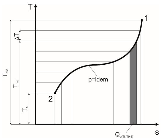
Figure 3.
The process of isobaric cooling of the heat source.
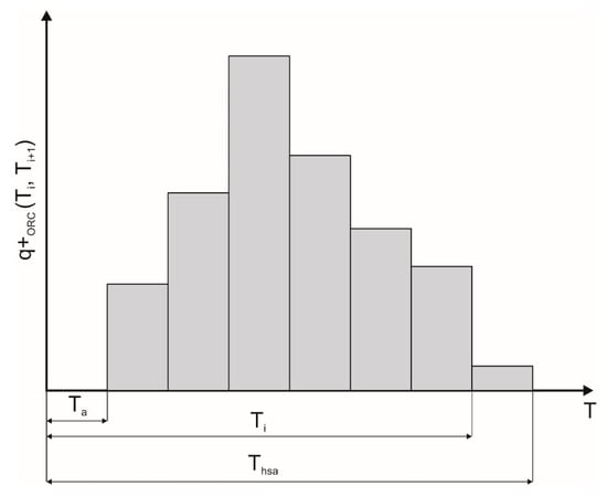
Figure 4.
Example of the heat source histogram.
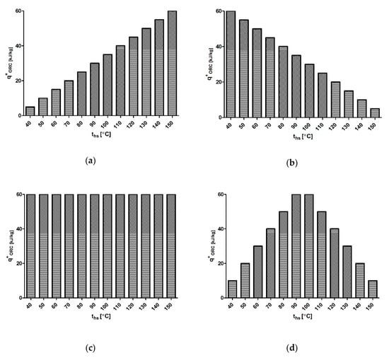
Figure 5.
Histograms of different heat sources: (a) ascending; (b) descending; (c) constant; (d) parabolic.
The course of the heat source cooling process is especially important in the case of assessment of the applicability of the working fluid for an ORC system employing a volumetric expander, which is treated in more detail in the following part of this paper.
To trace the influence of the heat source cooling rate, course, and the shape of the histogram on the ORC system operating parameters and working fluid selection, the following assumptions will be accepted in further reasoning:
- The process of heat extraction from the heat source is isobaric (such as presented in Figure 3),
- Working fluid vapor condensation is isobaric and occurs at condensation pressure p = p(Ta), where Ta ≈ Tc is ambient temperature,
- Temperature difference between vapor and coolant in the condenser is negligible,
- The pressure expansion ratio is defined as σP = p(Thsa)/p(Tc), (where Thsa is the initial temperature of the heat source),
- The expansion process in the expander is isentropic, and the value of pressure expansion ratio σP can be any real number,
- The amount of working fluid circulating in the cycle is equal to 1 kg,
- The power needed for pump driving is negligible,
- Expander is fed with vapor (liquid working fluid cannot be expanded).
For the above-listed assumptions, the following reasoning can be proceeded.
- If the heat source is cooled in the range of temperature , the obtained specific isentropic expansion work is equal to ,
- If the heat source is cooled in the range of temperature , the obtained specific isentropic expansion work is equal to ,
- If the heat source is cooled in the range of temperature , the obtained specific isentropic expansion work is equal to ,
where ΔT is the constant drop of the heat source temperature (it can be equal to, for example, ΔT = 10K).
Therefore, the working fluid expansion can be proceeded for a given pressure expansion ratio (σp) value until the temperature of the working fluid is equal to (or lower) than the equilibrium temperature for the pressure p1 = σp·p(Ta). Then, obtained hj values can be visualized for a given σP in the h = f(Ths) graph.
By performing the calculations for different values of the pressure expansion ratio (σP), a lEXS = f(σp) graph can be obtained. For a given heat source lEXS = f(σp), a graph can be plotted for different working fluids. By comparing the obtained results, the optimum pressure expansion ratio and working fluid can be selected (taking as the selection criterion the obtained values of the isentropic expansion work). What is also important, if a volumetric expander is applied in an ORC system, the obtained optimum pressure expansion ratio should fit in the range of the optimum (typical) pressure expansion ratio valid for the selected type of volumetric expander (see Table 1). Calculations can be performed for various heat source characteristics and histograms (see Figure 5).
In addition to the above-described method, the applicability of the working fluid to the ORC system can be assessed based on the comparison of the other assessment parameters. Figure 6, which is the basis for further considerations, shows the comparison of two ideal ORC power plant cycles (marked in blue and red lines) adopting two different low-boiling working fluids on the T–s plane. This graph is plotted with the assumption that both ORCs are supplied by the same heat source featuring the same heat supply temperature (Ths). Moreover, it is assumed that both cycles are cooled by the same heat sink featuring the same condensation temperature (Tc), and one of the substances is treated as the reference.
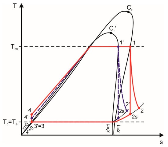
Figure 6.
Comparison of two ideal ORC cycles adopting two different working fluids in the T–s plane. 4–1—isobaric heating and evaporation of the working fluid in the evaporator, 1–2s—isentropic expansion of the working fluid vapor in the expander, 1–2—polytrophic expansion of the working fluid vapor in the expander, 2–3—isobaric cooling and liquefaction of the working fluid in the condenser, 3–4—isentropic forcing of the working fluid in the pump.
Working fluids can be compared using different rating parameters or criteria. The comparison can be based on the environmental impact of the working fluids (i.e., toxicity, ODP, HGWP, etc.) or their thermal parameters. Thermal parameters of the working fluid are of great importance from the design point of view, having an impact on the ORC system power, efficiency, and quality of operation. Particularly important thermal parameters of the working fluid are:
- Thermal capacity;
- Mean temperature of evaporation;
- Mean temperature of condensation;
- Heat of evaporation (i.e., preheating, vaporization, and superheating);
- Heat of condensation (i.e., cooling and liquefying);
- Pressure expansion ratio (i.e., pressure drop of the working fluid during expansion in the expander);
- Volumetric expansion ratio (i.e., change of specific volume of the working fluid during expansion in the expander);
- Volumetric expandability (i.e., the change of specific volume of the working fluid during the evaporation).
In the following, some dimensionless rating parameters, which can be applied for the comparison of two different workings using the above-listed thermal parameters, are defined. In addition to these rating parameters, it is necessary to state the following assumptions needed to carry out the comparison (see Figure 6 for details):
- The temperature of the heat source and the heat sink is the same for both working fluids;
- Temperature of working fluid chemical decomposition is lower than the temperature of the heat source (for both of the analyzed working fluids);
- One of the working fluids is treated as the reference substance.
3.1. The Influence of the Working Fluid Thermal Capacity
The working fluid selection, which is based on the comparison of thermal capacities of the working fluids can be, for example, proceeded if a quick heat source cooling is the priority of the ORC system operation. The rating parameter can be defined by the relation
where
where is the working fluid mass flow rate in the compared cycle, is the working fluid mass flow rate in reference cycle, is the heat extracted from the heat source by the working fluid during the evaporation in the compared cycle, is the heat extracted from the heat source by the working fluid during the evaporation in the reference cycle.
The comparison of two different working fluids and two different ORC cycles using the ψTC parameter gives the opportunity of selecting the working fluid that features a larger thermal capacity within the fixed parameters of the heat source, i.e., the working fluid in which the application can improve the cooling rate of the heat source and thus increase the amount of heat that is extracted from the heat source.
3.2. The Influence of the Mean Temperature of the Working Fluid Evaporation
The temperature of the working fluid evaporation strongly influences the thermal efficiency of the ORC system; therefore, it is an important property from the working fluid selection point of view. The rating parameter can be defined by the equation
where is the mean temperature of the evaporation (and heat supply) in the compared cycle, is the mean temperature of the evaporation (and heat supply) in the reference cycle, is the heat of the working fluid preheating, is the heat of the working fluid vaporization, is the heat of the working fluid superheating, is the change of the working fluid specific entropy during the preheating, evaporation, and superheating.
The comparison of two different working fluids and two different ORC cycles using the ψTME parameter gives the opportunity of selecting the working fluid that would enable harvesting of heat from the heat source at the highest possible mean heat extraction temperature Tmhs (i.e., the working fluid in which the application would improve the ORC system efficiency).
The process of the working fluid evaporation is composed of the consecutive processes of preheating, boiling, and superheating. The amount of heat needed to be extracted from the heat source to preheat the liquid working fluid to the starting point of the evaporation (see point a in Figure 1), to evaporate the liquid working fluid in the range of 0 < x < 1 (see line between points a and b in Figure 1) and to superheat the vapor of the working fluid (see line between points b and 1 in Figure 1) at a fixed heat source temperature (Ths) may vary for different working fluids.
In some ORCs, preheaters (regenerators) or coolers are applied (in the case of steam power plants also super heaters); therefore, the rating parameters should also be defined for these processes.
The rating parameter for preheating of the working fluid can be defined by the equation
where qPH1 is the amount of heat needed to be extracted from the heat source to preheat the working fluid in the compared cycle, is the amount of heat needed to be extracted from the heat source to preheat the working fluid in the reference cycle.
The rating parameter for vaporization of the working fluid can be defined by the equation
where is the amount of heat needed to be extracted from the heat source to vaporize the working fluid in the compared cycle, is the amount of heat needed to be extracted from the heat source to vaporize the working fluid in the reference cycle.
The rating parameter for superheating of the working fluid can be defined by the equation
where is the amount of heat needed to be extracted from the heat source to superheat the working fluid in the compared cycle, is the amount of heat needed to be extracted from the heat source to superheat the working fluid in the reference cycle.
The comparison of the different working fluids and different ORC cycles using ψPH, ψV, and ψSH rating parameters gives the opportunity of selecting the working fluid that would limit the amount of heat needed to be extracted from the heat source to preheat, evaporate, and eventually superheat the working fluid and thus to minimize the heat transfer area and dimensions of the applied preheater, evaporator, and superheater.
3.3. The Influence of the Mean Temperature of Working Fluid Condensation
The temperature of condensation also strongly influences the thermal efficiency of the ORC system; therefore, it is an important parameter from the working fluid selection point of view. The rating parameter can be defined by the equation
where is the mean temperature of the condensation in the compared cycle, is the mean temperature of the condensation in the reference cycle, is the heat of working fluid cooling, is the heat of the working fluid liquefaction, is the change in the working fluid specific entropy during cooling and liquefaction.
The comparison of two different working fluids and two different ORCs using the ψTMC parameter gives the opportunity of selecting the working fluid that will reject heat at the lowest possible heat rejection temperature Tc ≈ Ta, i.e., the working fluid that will allow to lower the temperature of the heat sink and, therefore, increase the ORC system efficiency.
The process of the working fluid condensation is composed of the consecutive processes of cooling and liquefying. Rating parameters can also be defined for these sequential processes.
The amount of heat needed to be rejected from the working fluid to heat sink, to cool the vapor of the working fluid in the range of vapor quality of 0 < x < 1 (see line between points 2 and c in Figure 1), and to liquefy the working fluid vapor (see line between points c and 3 in Figure 1) at a fixed heat sink temperature (Tc) may vary for different working fluids.
The rating parameter for cooling of the working fluid vapor can be defined by the equation
where is the amount of heat that has to be rejected from the working fluid to the heat sink to cool the working fluid in the compared cycle, is the amount of heat that has to be rejected from the working fluid to the heat sink to cool the working fluid in the reference cycle.
The rating parameter for liquefying the working fluid vapor can be defined by the equation
where is the amount of heat that has to be rejected from the working fluid to heat sink to liquefy the working fluid in the compared cycle, is the amount of heat that has to be rejected from the working fluid to the heat sink to liquefy the working fluid in the reference cycle.
The comparison of the different working fluids and different ORCs using the ψTMC, ψC, and ψL rating parameters gives the opportunity of selecting the working fluid that will limit the amount of heat needed to be rejected from the working fluid to heat sink to cool and liquefy the working fluid vapor and thus to lower the heat transfer area and dimensions of the applied cooler and condenser.
3.4. The Influence of the Pressure and Volumetric Expansion Ratio
The pressure and volumetric expansion ratio are important rating parameters influencing the pressure range in the cycle and operating conditions of the applied expander.
Pressure expansion ratio is given by the equation
where is the working fluid pressure at the inlet to the expander, is the working fluid pressure at the outlet from the expander.
The volumetric expansion ratio is given by the equation
where is the specific volume of the working fluid at the inlet to the expander, is the specific volume of the working fluid at the outlet from the expander.
The pressure expansion ratio σp describes the variation of the working fluid pressure during the expansion in the expander. This parameter can be applied for comparative analyses of the working fluids in terms of decreasing the pressure difference in the cycle and, in this way, simplifying the technical design of the ORC system (i.e., a lower pressure difference in the cycle means simpler sealing or thinner tubes can be applied). This parameter can also be used for selecting the volumetric expander in an ORC system using a specific working fluid and specific heat source and heat sink.
The volumetric expansion ratio σv describes the variation of the working fluid specific volume during the expansion in the expander. This parameter can be applied for comparative analyses of the working fluids in terms of increasing the specific volume of the working fluid during the expansion process. It may also be applied for selecting the volumetric expander in an ORC system using specified working fluid and a specified heat source and heat sink.
3.5. The Influence of the Volumetric Expandability of the Working Fluid during the Evaporation
The volumetric expandability of the working fluid during evaporation is another important parameter that has an influence on the selection of the volumetric expander in an ORC system. Volumetric expanders are usually characterized by a specified vapor consumption, which depends on the geometrical dimensions of the expander and rotational speed of the rotor (or shaft), i.e., the cycle frequency.
Volumetric expandability can be described by the equation
where is the specific volume of the working fluid at the outlet of the evaporator, is the specific volume of the working fluid at the inlet to the evaporator.
The comparison of the different working fluids and different ORC cycles using the σV parameter gives the opportunity of selecting the working fluid for a specific volumetric expander or selecting the volumetric expander in a specified ORC system working with specified working fluid. This parameter can be useful for comparative analysis of working fluids in terms of the increase of the specific volume of the working fluid, i.e., the amount of vapor that can be obtained via evaporation of 1 kg of liquid working fluid.
In addition to the above-mentioned rating parameters, it is possible to define others related to, for example, critical parameters of the working fluids or their thermal properties, such as thermal conductivity, kinematic viscosity, thermal capacity, and others. However, these parameters will not be analyzed in the present study.
The above-defined rating parameters can be treated together as the working fluid selection method and applied for comparative selection of the working fluid for the ORC system, if the thermal characteristics of the heat source and the heat sink (namely the heat source and the heat sink temperatures) are known. The selection is based on the obtained maximum or minimum values of the rating parameters. Moreover, based on the comparison of the calculated parameters and the values of the expansion ratios, as well as the values of specific expansion work, it is possible to select a suitable volumetric expander for an ORC system.
The weight and importance of the rating parameters are always connected with the application of the ORC system. For example, if an ORC system is applied for cooling the machines and extracting heat from cooling mediums (e.g., in the case of internal combustion engines), heat removal from the cooling medium is the priority. Therefore, the most important rating parameter, in this case, will be the thermal capacity parameter (ψTC), and the maximum value of this parameter should be treated as the priority during the selection of the expander and working fluid.
In the following paragraph, a comparative analysis of selected working fluids using the above-described method is presented.
4. Comparative Analysis of the Working Fluids
4.1. The Analysis of the Influence of the Heat Source Characteristic and Histogram on the Pressure Expansion Ratio and the Obtained Isentropic Expansion Work
The analysis of the influence of the heat source characteristic and histogram on the pressure expansion ratio and the obtained isentropic expansion work was performed for histograms presented in Figure 5a–d. For the sake of clarity of the presented results, four working fluids (i.e., R123, R124, R134a, and R245fa) were selected for this comparison from the working fluids listed in Table 2. Calculations were performed for the following assumptions:
- Heat source temperature varies in the range of ths = 40–150 °C,
- Specific heat, which is supplied to the ORC system from the heat source, is calculated using the relation ,
- Heat sink temperature is equal to tc = 20 °C,
- Theoretical efficiency of the ORC cycle is calculated using the relation ,
- Specific isentropic expansion work is calculated using the relation ,
- Heat source histograms have a course such as that presented in Figure 5a–d.
It should be reminded here again that each type of the volumetric expander features a specific highest value and optimum range of pressure expansion ratio σP (this parameter is also dependent on the design of the machine, i.e., its geometrical dimensions) for which the expander reaches the highest efficiency and power. The operational parameters of the expander should be kept in the range enabling the exploitation of the machine within the optimum range of the pressure expansion ratio. This issue was treated in more detail in [3,4]. For example, in the case of a multi-vane expander, it was reported in [57,58] that the highest internal efficiency is achieved for the value of σP ≈ 5, and further increasing of the pressure expansion ratio has no effect on the expanders’ internal efficiency. Examples of the influence of the pressure expansion ratio and rotational speed of the expander shaft on the expander power output are presented in Figure 7. As can be seen from this Figure, each curve has a visible maximum within a different range of rotational speed and pressure expansion ratio. Therefore, in order to keep the proper expander operating conditions and high values of the efficiency and power output, the machine operational parameters (i.e., rotational speed, pressure expansion ratio) should be regulated in a way that will enable to keep their values in a range located near the curve maximum.
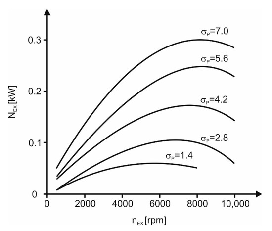
Figure 7.
The influence of the expansion ratio and rotational speed of the expander shaft on the expander power output.
As reported in Table 1, each volumetric expander features the maximum value of the pressure expansion ratio (reaching σp = 200 for piston expanders). However, to the knowledge of the author, piston expanders reaching such a high pressure expansion ratio are not yet successfully applied in ORC systems. Therefore, in the following considerations, the obtained calculation results are limited to the value of σp = 15, which is the typical value of the highest pressure expansion ratio obtained experimentally in volumetric expanders that are successfully applied in commercial and research ORC units (i.e., screw, scroll, and multi-vane expanders). Figure 8 visualizes the variation of the isentropic expansion work for different characteristics of the heat source (i.e., histograms).
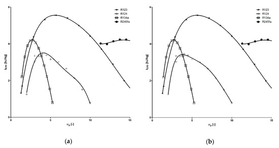
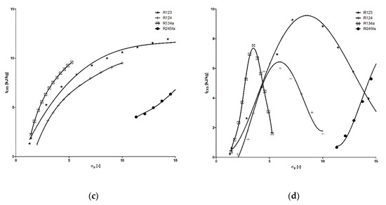
Figure 8.
The variation of isentropic expansion work vs. pressure expansion ratio: (a) graph valid for the heat source histogram presented in Figure 5a; (b) graph valid for the heat source histogram presented in Figure 5b; (c) graph valid for heat source histogram presented in Figure 5c; (d) graph valid for the heat source histogram presented in Figure 5d.
Figure 8a is valid for the histogram presented in Figure 5a. In the analyzed range of the pressure expansion ratio, the highest values of the isentropic expansion work are obtained for R123 (with the maximum value obtained for a pressure expansion ratio of σp ≈ 6.5). For R134a, R124, and R245fa, the highest values of the isentropic expansion work were obtained for the pressure expansion ratio of σp ≈ 3.5, σp ≈ 4.8, and σp ≈ 15, correspondingly. Similar results (see Figure 8b) were obtained for the heat source histogram presented in Figure 5b.
Different shapes of the characteristics (see Figure 8c) were obtained for the heat source histogram presented in Figure 5c. The highest value of isentropic expansion work was obtained for R123 and the pressure expansion ratio of σp ≈ 15. For R134a, R124, and R245fa, the highest values of the isentropic expansion work were obtained for the pressure expansion ratio of σp ≈ 5, σp ≈ 10, and σp ≈ 15, respectively.
Figure 8d visualizes the characteristics obtained for the heat source characteristics presented in Figure 5d. The highest values of isentropic expansion work are obtained for the pressure expansion ratio of σp ≈ 9, σp ≈ 15, σp ≈ 4, and σp ≈ 6 for R123, R245fa, R134a, and R124, respectively.
By a comparative analysis of the results, which are visualized in Figure 8, the working fluid can be selected for the ORC system employing a specified volumetric expander, or a volumetric expander can be selected for the ORC system utilizing a specified working fluid. For example, as was previously stated, the optimum pressure expansion ratio ranges between four and five for multi-vane expanders that are applied in ORCs.
Therefore, if the highest value of the isentropic expansion work would be considered as the main working fluid selection criterion and the multi-vane expander would be considered as the prime mover in the ORC system, R123 (in the case of heat source histograms presented in Figure 5a,b) and R134a (in the case of heat source histograms presented in Figure 5c,d) are the working fluids in which the application should potentially result in the highest expander power.
4.2. The Comparative Analysis of the Working Fluids Using Rating Parameters
In the following part of this section, the comparative analysis of the working fluids using the rating parameters described in Section 3.2, Section 3.3, Section 3.4 and Section 3.5 is presented. The analysis was performed for working fluids listed in Table 2 according to the process layout visualized in Figure 6. The values of thermal properties of the working fluids (i.e., specific enthalpy, specific entropy, etc.) were calculated using the CoolProp software.
The following assumptions were accepted for calculations:
- Cycle is evaporative, and superheating is not applied,
- Temperature of the heat source ranges between 40 °C and 150 °C,
- Expander internal efficiency is equal to ηi = 0.7, which is a typical mean value of volumetric expander internal efficiency [29],
- Temperature of the heat sink is equal to tc = 20 °C,
- The reference substance is R123, which was selected based on the positive results of experiments on this working fluid, which were conducted by the author using the test-stands described in [29,30],
- ORC system is operating as the power plant (i.e., there is no heat generated for central heating),
- Heat losses in the ORC system are negligible.
The earlier defined rating parameters (i.e., ψTC, ψTME, ψPH, ψV, ψTMC, ψC, ψL) together with the pressure and volumetric expansion ratio (σP, σVEX), volumetric expandability (σV), efficiency of the cycle (ηORC), and expander specific work (lEX) were calculated for each of the above-mentioned working fluids. ψSH was not calculated because superheating is not considered in the present study. The results of these calculations are visualized in Figure 9, Figure 10, Figure 11, Figure 12, Figure 13, Figure 14, Figure 15, Figure 16, Figure 17, Figure 18 and Figure 19. For the same reason as in the case of Figure 8, Figure 9, Figure 10, Figure 11, Figure 12, Figure 13, Figure 14, Figure 15, Figure 16, Figure 17, Figure 18 and Figure 19 are limited to the value of σp = 15.
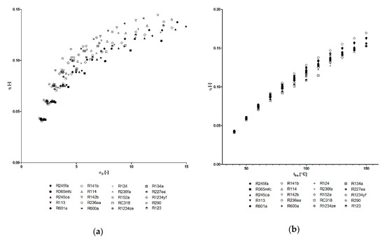
Figure 9.
The variation of ORC system efficiency vs. pressure expansion ratio and heat source temperature: (a) η = f(σP); (b) η = f(ths).
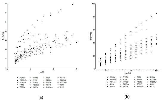
Figure 10.
The variation of isentropic expansion work vs. pressure expansion ratio and heat source temperature: (a) lex = f(σP); (b) lex = f(ths).
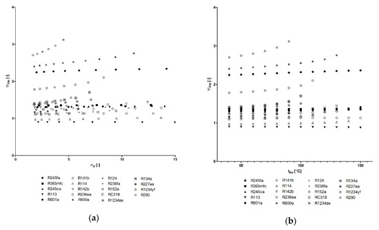
Figure 11.
The variation of the ψPH parameter vs. the pressure expansion ratio and heat source temperature: (a) ψPH = f(σP); (b) ψPH = f(ths).
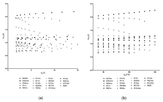
Figure 12.
The variation of the ψTC parameter vs. the pressure expansion ratio and heat source temperature: (a) ψTC = f(σP); (b) ψTC = f(ths).
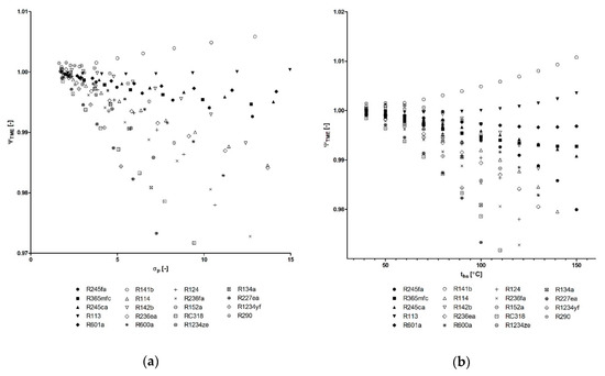
Figure 13.
The variation of ψTME parameter vs. pressure expansion ratio and heat source temperature: (a) ψTME = f(σP); (b) ψTME = f(ths).
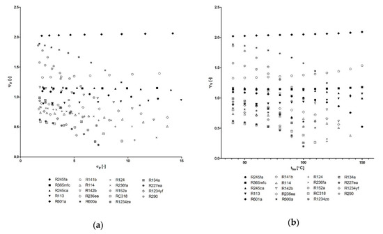
Figure 14.
The variation of the ψV parameter vs. the pressure expansion ratio and heat source temperature: (a) ψV = f(σP); (b) ψTME = f(ths).
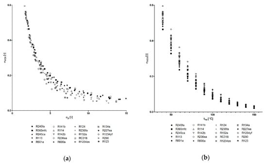
Figure 15.
The variation of the σVEX parameter vs. pressure expansion ratio and heat source temperature: (a) σVEX = f(σP); (b) σVEX = f(ths).
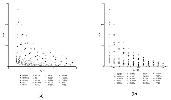
Figure 16.
The variation of the σV parameter vs. the pressure expansion ratio and heat source temperature: (a) σV = f(σP); (b) σV = f(ths).
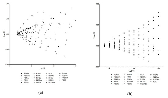
Figure 17.
The variation of the σV parameter vs. the pressure expansion ratio and heat source temperature: (a) σTMC = f(σP); (b) σTMC = f(ths).
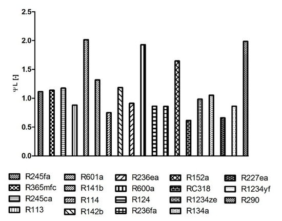
Figure 18.
The variation of the ψL rating parameter (graph is valid for the heat sink temperature of tc = 20 °C).
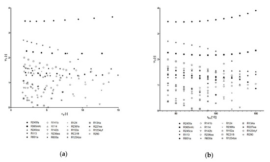
Figure 19.
The variation of the ψC parameter vs. the pressure expansion ratio and heat source temperature: (a) ψC = f(σP); (b) ψC = f(ths).
Figure 9a shows the variation of ORC system efficiency vs. pressure expansion ratio. The highest efficiency (ca. 14%) was achieved for R142b and a pressure expansion ratio of σp ≈ 12.5. Lower (but higher than in the case of R123) values of ORC system efficiency were obtained for R290, R600a, R152a, R124, R114, R1234ze, R1234yf, R227ea.
For the other working fluids, the obtained ORC system efficiency is lower than in the case of R123. The variation of ORC system efficiency vs. heat source temperature, which is presented in Figure 9b, shows that the maximum value of the ORC system efficiency is obtained for R141b in the considered range of heat source temperature. For example, if a multi-vane machine is selected as the expander, thence within the range of optimum pressure expansion ratio of these machines, the highest efficiency of the ORC system (ranging between 10% and 11%) was achieved for R290.
Figure 10a visualizes the variation of specific expansion work (lex) vs. the pressure expansion ratio. The highest value (ca. 70 kJ/kg) of specific expansion work was obtained for R601a and pressure expansion ratio σp ≈ 15. Lower (but higher than in the case of R123) values of expansion work were obtained for R290, R600a, R142b, R141b, R245fa, R245ca, R134a, R1234yf, R365mfc, and R1234ze, which means that at the same working fluid mass flow rate through the expander, a higher power of the expander can be obtained using these working fluids compared to R123. For other working fluids, obtained values of isentropic expansion work were lower than for R123. The variation of expansion work vs. temperature of the heat source, which is presented in Figure 10b, shows that the highest value of specific expansion work is achieved for R601a in the considered range of heat source temperature. For example, if a multi-vane machine is selected as the expander, then within the range of the optimum pressure expansion ratio of these machines, the highest value of isentropic expansion work ranges between 35 and 40 kJ/kg and is obtained for R290 and R601a, correspondingly. Figure 11 shows the variation of the ψPH rating parameter vs. the pressure expansion ratio (see Figure 11a) and temperature of the heat source (see Figure 11b). The lowest values of this parameter (ψPH < 1) were achieved for R113 and R114 in the considered range of the pressure expansion ratio and heat source temperature.
Therefore, if the main criterion of the working fluid selection would be limiting the amount of heat required to preheat the working fluid (see process 4-a in Figure 1) and, therefore, to limit the heat transfer area and dimensions of the preheater, these working fluids are promising. For some working fluids analyzed (R600a, R601a, and R290), the amount of heat required to preheat the working fluid is even two or three times bigger than in the case of R123. For example, if the main application purpose of the ORC system is to exploit the heat source as much as possible (e.g., in the case of ORC application for waste heat recovery from piston engine cooling systems, etc.), these working fluids would be promising in that case.
Figure 12 shows the variation of the ψTC rating parameter vs. the pressure expansion ratio (see Figure 12a) and temperature of the heat source (see Figure 12b). The lowest values of this parameter (ψTC < 1) were achieved for RC318 and R227ea in the considered range of the pressure expansion ratio and heat source temperature.
Thus, if the main criterion of the working fluid selection would be limiting the amount of heat required for the working fluid phase transition (liquid–gas) to proceed (see process 4-b in Figure 1), these working fluids are promising in that case. For some working fluids analyzed (R600a, R601a, and R290), the amount of heat required to preheat the working fluid is even two times bigger than in the case of R123. For example, if the main application purpose of the ORC system is to exploit the heat source as much as possible (e.g., in the case of ORC application for waste heat recovery from piston engine cooling systems, etc.) these working fluids would be promising in that case.
Figure 13 shows the variation of the ψTME rating parameter vs. the pressure expansion ratio (see Figure 13a) and temperature of the heat source (see Figure 13b). The lowest values of this parameter (ψTME < 1) were achieved for RC318 and R227ea in the considered range of the pressure expansion ratio and heat source temperature. Therefore, if the main criterion of the working fluid selection would be lowering the heat source temperature (i.e., cooling the heat source) during the liquid–gas phase transition of the working fluid (see process 4-a in Figure 1), these working fluids are promising in that case. For some working fluids (R141b, R290, and R142b), the mean temperature of heat supply is higher than for R123 (ψTME > 1). If the purpose of the ORC system operation is heat extraction from the heat source at possibly high temperatures, these working fluids are promising in that case.
Figure 14 shows the variation of the ψV rating parameter vs. the pressure expansion ratio (see Figure 14a) and temperature of the heat source (see Figure 14b). The lowest values of this parameter (ψV < 1) were achieved for R1234yf and R227ea in the considered range of the pressure expansion ratio and heat source temperature. Thus, if the main criterion of working fluid selection would be lowering the heat amount that is required to evaporate the working fluid (see process a-b in Figure 1) and, therefore, to lower the heat transfer area and dimensions of the evaporator, these working fluids are promising in that case. For some working fluids (R600a, R601a, and R290), the amount of heat required to preheat the working fluid is even 1.5–2 times bigger than in the case of R123. For example, if the main application purpose of the ORC system is to exploit the heat source as much as possible (e.g., in the case of ORC application for waste heat recovery from piston engine cooling systems, etc.), these working fluids would be promising in that case.
Figure 15a visualizes the variation of the volumetric expansion ratio σVEX vs. the pressure expansion ratio. The volumetric expansion ratio is an important design parameter of the volumetric expander, which has an influence on the machine dimensions and volume of the working chambers in a way that determines the gas flow capacity of a machine.
Figure 15a visualizes the variation of the volumetric expansion ratio σVEX vs. the pressure expansion ratio. The volumetric expansion ratio is an important design parameter of the volumetric expander that has an influence on the machine dimensions and volume of the working chambers in a way that determines the gas flow capacity of a machine. Figure 16 shows the variation of the volumetric expandability σV vs. the pressure expansion ratio (see Figure 16a) and temperature of the heat source (see Figure 16b). In the case of volumetric machines, the volumetric flow of gas at the inlet to the expander is related to machines’ gas flow capacity and should be kept at the required level in order to provide the continuity of machine operation and optimum operating conditions (rotational speed, efficiency, and power output). Therefore, this parameter should be maximized in the case of ORCs employing volumetric expanders. The highest values of this parameter (σV = 50–270) were achieved for R113, R365mfc, and R141b in the considered range of the pressure expansion ratio and heat source temperature.
Figure 17 shows the variation of the ψTMC rating parameter vs. the pressure expansion ratio (see Figure 17a) and temperature of the heat source (see Figure 17b).
The lowest values of this parameter (ψTMC < 1) were achieved for R290, R1234yf, R124, and R142b in the considered range of the pressure expansion ratio and heat source temperature. Thus, if the main criterion of the working fluid selection would be to lower the heat sink temperature, these working fluids are promising in that case. For some working fluids (RC318, R601a, and R365mfc), the average temperature of heat rejection is higher than for R123 (ψTMC > 1). Therefore, if the main criterion of working fluid selection would be to increase the temperature of the heat sink, these working fluids are promising in that case.
Figure 18 shows the variation of the ψL rating parameter for analyzed working fluids in the form of a bar graph (the graph is valid only for the assumed constant temperature of the heat sink, i.e., tc = 20 °C). The lowest values of this parameter (ψL < 1) were achieved for RC318 and R227ea in the considered range of the ORC system operating parameters. Thus, if the main criterion of the working fluid selection would be limiting the amount of heat rejected from the gas during cooling (see process 2-c in Figure 1) and additionally limiting the heat transfer area and dimensions of the system cooler, these working fluids are promising in that case.
Figure 19 shows the variation of the ψC rating parameter vs. the pressure expansion ratio (see Figure 19a) and temperature of the heat source (see Figure 19b).
The lowest values of this parameter (ψC < 1) were achieved for R134a, R142b, R152a, R290, and R124 in the considered range of the pressure expansion ratio and heat source temperature. Thus, if the criterion of the working fluid selection would be limiting the amount of heat rejected by the working fluid during condensation (see process c-3 in Figure 1) and additionally limiting the heat transfer area and dimensions of the system condenser, these working fluids are promising in that case.
4.3. Summary
The first set of calculations was related to the working fluid selection, which is based on the variation of isentropic expansion work vs. the pressure expansion ratio σP and characteristic (i.e., histogram) of the heat source. If the highest value of isentropic expansion work would be considered as the main working fluid selection criterion, R123 seems to be a promising working fluid reaching the highest values of the expansion work in a wide range of the studied conditions and for all characteristics of the heat source. For other working fluids studied, the obtained values of isentropic expansion work are lower than in the case of R123. However, if additional working fluid selection criteria (which are related to the type of the applied volumetric expander and its design, such as pressure expansion ratio) are considered, then calculation results proved that other working fluids are also promising in the case of different types of volumetric expanders. Differences are related to the heat source characteristics. For example, if the highest value of the isentropic expansion work would be considered as the working fluid selection criterion and the multi-vane expander (featuring the optimum pressure expansion ratio of 4–5) as the prime mover of the ORC system, R123 (for the heat source histogram presented in Figure 5a,b) and R134a (for the heat source histogram presented in Figure 5c,d) are the working fluids in which the application should potentially result in the highest obtained expander power.
The second set of calculations was related to the comparative analysis of the working fluids based on the defined rating parameters (ψTC, ψTME, ψPH, ψV, ψTMC, ψC, ψL) together with pressure and the volumetric expansion ratio (σP, σVEX), volumetric expandability (σV), efficiency of the cycle (ηORC), and specific expansion work (lEX). R123 was selected as the reference substance based on the positive results of experiments on this working fluid, which were proceeded by the author using the test-stands and the results of the first part of calculations. The values of the rating parameters were calculated for 20 selected working fluids (see Table 2). Obtained results were then plotted in figures and compared. It was found that some of the analyzed working fluids have better thermal properties than the reference R123, i.e.,
- Highest values of the ORC system efficiency were obtained for R142b. However, it was found that the application of R290, R600a, R152a, R124, R114, R1234ze, R1234yf, R227ea can also result in a higher cycle efficiency than in the case of R123.
- Highest values of the specific expansion work were obtained for R601a. Moreover, it was found that the application of R290, R600a, R142b, R141b, R245fa, R245ca, R134a, R1234yf, R365mfc, and R1234ze can also result in higher values of the specific expansion work than R123, which means that at the same working fluid mass flow rate through the expander, a higher expander power can be obtained using these working fluids compared to R123.
- Application of RC318 and R227ea can limit the required amount of heat that is needed to be supplied to the working fluid from the heat source to perform the liquid–gas phase transition. The obtained results showed that by the application of R600a, R601a, and R290, the amount of required heat can be increased, which can be important if the application of the ORC system for cooling machines or devices is considered.
- By the application of RC318 and R227ea, it is possible to lower the temperature of the heat source (i.e., mean temperature of the heat supply) during the liquid–gas phase transition more rapidly compared to R123. It was also found that by the application of R141b, R290, and R142b, it is possible to extract heat from the heat source at higher temperatures compared to R123.
- By the application of R113 and R114, the amount of heat required to preheat the working fluid can be limited compared to R123, and therefore, the heat transfer area and dimensions of the preheater can be lowered. On the other hand, the application of R600a, R601a, and R290 can increase the amount of heat required to preheat the working fluid, which can be important if the application of the ORC system for cooling machines or devices is considered.
- By the application of R1234yf and R227ea, it is possible to limit the amount of heat required to evaporate the working fluid and, therefore, lower the heat transfer area and dimensions of the evaporator compared to R123. On the other hand, the application of R600a, R601a, and R290 can increase the amount of heat required to preheat the working fluid, which can be important when the application of an ORC system for cooling machines or devices is considered.
- The lowest values of the volumetric expansion ratio were obtained for R1234yf and R227ea, while the maximum values were achieved for R152a and R141b in the considered range of the pressure expansion ratio. In the considered range of the heat source temperature, the lowest values of this parameter were obtained for R365mfc, R113, and R245ca, while the maximum values were achieved for R152a and R600a. The value of this parameter can be minimized (if a smaller expander is needed) or maximized (if a larger expander is needed).
- The highest values of volumetric expandability (high values of which are positive if a volumetric machine is considered as the ORC expander) were obtained for R113, R365mfc, and R141b.
- By the application of R290, R1234yf, R124, and R142b, it is possible to lower the temperature (i.e., mean temperature of the working fluid liquefaction) of the heat source during the gas–liquid phase transition more rapidly compared to R123. By the application of RC318, R601a, and R365mfc, it is possible to reject heat at higher temperatures compared to R123.
- By the application of RC318 and R227ea, it is possible to limit the amount of heat that is required to cool the gaseous working fluid and, therefore, lower the heat transfer area and dimensions of the cooler compared to R123.
- By the application of R134a, R142b, R152a, R290, and R124, it is possible to limit the amount of heat that is required to liquify the working fluid vapor and, therefore, lower the heat transfer area and dimensions of the condenser compared to R123.
5. Summary and Conclusions
This study presents the comparative method of the working fluid selection for an ORC system powered by a low temperature heat source and employing a volumetric expander. This method is based on a comparison of the selected thermal properties of working fluids by the application of the rating parameters describing the following thermal properties of the working fluids: the working fluid thermal capacity, mean temperature of evaporation, mean temperature of condensation, pressure and volumetric expansion ratio, volumetric expandability, as well as the heat of preheating, vaporization, superheating, cooling, and liquefaction. Moreover, isentropic expansion work was considered as the rating parameter. The presented method can be used for selecting the working fluid for the ORC system, which is supplied by a heat source and heat sink featuring a specified thermal power and temperature. Moreover, using this method, it is possible to select the volumetric expander for the ORC system based on the comparison of the calculated parameters, the pressure expansion ratio, and specific expansion work. The proposed method is universal and can be easily adopted for different working fluids, different assumptions, and ORCs employing turbines as the expanders. Therefore, using this method, it is possible to compare many different ORCs powered by different heat sources. The method can also be applied for comparing different ORCs to classical steam power plants. In order to illustrate this treatment, sets of calculations were performed in order to give an outlook for the selection of working fluids and a volumetric expander. Special attention was paid to a multi-vane expander. The calculation results showed the comparison of the working fluid candidates for different operating conditions of an ORC system. These results can be helpful for scientists and engineers dealing with ORCs and volumetric expanders for making quick estimations and comparisons of different ORCs.
Funding
This research received no external funding.
Acknowledgments
The author would like to thank Attila R. Imre for the invitation to publish this article.
Conflicts of Interest
The author declares no conflict of interest.
References
- Bao, J.; Zhao, L. A review of working fluid and expander selections for organic Rankine cycle. Renew. Sustain. Energy Rev. 2013, 24, 325–342. [Google Scholar] [CrossRef]
- Lai, N.A.; Wendland, M.; Fischer, J. Working fluid for high-temperature organic Rankine cycles. Energy 2011, 36, 199–211. [Google Scholar] [CrossRef]
- Gnutek, Z.; Kolasiński, P. The application of rotary vane expanders in ORC systems—Thermodynamic description and experimental results. J. Eng. Gas Turbines Power 2013, 135, 61901. [Google Scholar] [CrossRef]
- Gnutek, Z. Sliding-Vane Rotary Machinery. Developing Selected Issues of One-Dimensional Theory; Wrocław University of Technology Publishing: Wrocław, Poland, 1997. [Google Scholar]
- Usman, M.; Pesyridis, A.; Cockerill, S.; Howard, T. Development and Testing of a Free Piston Linear Expander for Organic Rankine Cycle Based Waste Heat Recovery Application. In Proceedings of the 5th International Seminar on ORC Power Systems, Athens, Greece, 9–11 September 2019. [Google Scholar]
- Kaczmarczyk, T.; Ihnatowicz, E.; Żywica, G.; Kiciński, J. Experimental investigation of the ORC system in a cogenerative domestic power plant with a scroll expanders. Open Eng. 2015, 5, 411–420. [Google Scholar] [CrossRef]
- Gao, P.; Jiang, L.; Wang, L.W.; Wang, R.Z.; Song, F.P. Simulation and experiments on an ORC system with different scroll expanders based on energy and exergy analysis. Appl. Therm. Eng. 2015, 75, 880–888. [Google Scholar] [CrossRef]
- Jradi, M.; Li, J.; Liu, H.; Riffat, S. Micro-scale ORC-based combined heat and power system using a novel scroll expander. Int. J. Low Carbon Technol. 2014, 9, 91–99. [Google Scholar] [CrossRef][Green Version]
- Hsu, S.-W.; Chiang, H.-W.D.; Yen, C.-W. Experimental Investigation of the Performance of a Hermetic Screw-Expander Organic Rankine Cycle. Energies 2014, 7, 6172–6185. [Google Scholar] [CrossRef]
- Zhang, Y.-Q.; Wu, Y.-T.; Xia, G.-D.; Ma, C.-F.; Ji, W.-N.; Liu, S.-W.; Yang, K.; Yang, F.-B. Development and experimental study on organic Rankine cycle system with single-screw expander for waste heat recovery from exhaust of diesel engine. Energy 2014, 77, 499–508. [Google Scholar] [CrossRef]
- Tang, H.; Wu, H.; Wang, X.; Xing, Z. Performance study of a twin-screw expander used in a geothermal organic Rankine cycle power generator. Energy 2015, 90, 631–642. [Google Scholar] [CrossRef]
- Öhman, H.; Lundqvist, P. Screw expanders in ORC applications, review and a new perspective. In Proceedings of the 3rd International Seminar on ORC Power Systems, Brussels, Belgium, 12–14 October 2015. [Google Scholar]
- Więckiewicz, H.; Cantek, L. Volumetric Compressors—Atlas, 2nd ed.; Gdańsk University of Technology Publishing: Gdańsk, Poland, 1985. [Google Scholar]
- Kim, Y.M.; Shin, D.G.; Kim, C.G. Optimization of Design Pressure Ratio of Positive Displacement Expander for Vehicle Engine Waste Heat Recovery. Energies 2014, 7, 6105–6117. [Google Scholar] [CrossRef]
- Dumont, O.; Parthoens, A.; Dickes, R.; Lemort, V. Experimental investigation and optimal performance assessment of four volumetric expanders (scroll, screw, piston and roots) tested in a small-scale organic Rankine cycle system. Energy 2018, 165, 1119–1127. [Google Scholar] [CrossRef]
- Latz, G.; Erlandsson, O.; Skåre, T.; Contet, A.; Andersson, S.; Munch, K. Performance Analysis of a Reciprocating Piston Expander and a Plate Type Exhaust Gas Recirculation Boiler in a Water-Based Rankine Cycle for Heat Recovery from a Heavy Duty Diesel Engine. Energies 2016, 9, 495. [Google Scholar] [CrossRef]
- Bianchi, M.; Branchini, L.; Casari, N.; De Pascale, A.; Melino, F.; Ottaviano, S.; Pinelli, M.; Spina, P.R.; Suman, A. Experimental analysis of a micro-ORC driven by piston expander for low-grade heat recovery. Appl. Therm. Eng. 2019, 148, 1278–1291. [Google Scholar] [CrossRef]
- Wronski, J.; Imran, M.; Skovrup, M.J.; Haglind, F. Experimental and numerical analysis of a reciprocating piston expander with variable valve timing for small-scale organic Rankine cycle power systems. Appl. Energy 2019, 247, 403–416. [Google Scholar] [CrossRef]
- Oudkerk, J.F.; Dickes, R.; Dumont, O.; Lemort, V. Experimental performance of a piston expander in a small- scale organic Rankine cycle. Iop Conf. Ser. Mater. Sci. Eng. 2015, 90, 12066. [Google Scholar] [CrossRef]
- Glavatskaya, Y.; Podevin, P.; Lemort, V.; Shonda, O.; Descombes, G. Reciprocating Expander for an Exhaust Heat Recovery Rankine Cycle for a Passenger Car Application. Energies 2012, 5, 1751–1765. [Google Scholar] [CrossRef]
- Li, G.; Zhang, H.; Yang, F.; Song, S.; Chang, Y.; Yu, F.; Wang, J.; Yao, B. Preliminary Development of a Free Piston Expander–Linear Generator for Small-Scale Organic Rankine Cycle (ORC) Waste Heat Recovery System. Energies 2016, 9, 300. [Google Scholar] [CrossRef]
- Song, P.; Wei, M.; Liu, Z.; Zhao, B. Effects of suction port arrangements on a scroll expander for a small scale ORC system based on CFD approach. Appl. Energy 2015, 150, 274–285. [Google Scholar] [CrossRef]
- Emhardt, S.; Tian, G.; Chew, J. A review of scroll expander geometries and their performance. Appl. Therm. Eng. 2018, 141, 1020–1034. [Google Scholar] [CrossRef]
- Kim, D.; Chung, H.J.; Jeon, Y.; Jang, D.S.; Kim, Y. Optimization of the injection-port geometries of a vapor injection scroll compressor based on SCOP under various climatic conditions. Energy 2017, 135, 442–454. [Google Scholar] [CrossRef]
- Li, J.; Yang, F.; Zhang, H.; Wu, Z.; Tian, Y.; Hou, X.; Xu, J.; Ren, J. Comparative analysis of different valve timing control methods for single-piston free piston expander-linear generator via an orthogonal experimental design. Energy 2020, 116966. [Google Scholar] [CrossRef]
- Read, M.; Smith, I.K.; Stosic, N. Optimisation of Screw Expanders for Power Recovery from Low Grade Heat Sources. Energy Technol. Policy 2014, 1, 131–142. [Google Scholar] [CrossRef]
- Smith, I.K.; Stosic, N.; Kovacevic, A. Power Recovery from Low Grade Heat by Means of Screw Expanders; Elsevier: Cambridge, UK, 2014. [Google Scholar]
- Lemmon, E.W.; Bell, I.H.; Huber, M.L.; McLinden, M.O. NIST Standard Reference Database 23: Reference Fluid Thermodynamic and Transport Properties-REFPROP, Version 10.0; National Institute of Standards and Technology, Standard Reference Data Program: Gaithersburg, MD, USA, 2018.
- Bell, I.H.; Wronski, J.; Quoilin, S.; Lemort, V. Pure and Pseudo-pure Fluid Thermophysical Property Evaluation and the Open-Source Thermophysical Property Library CoolProp. Ind. Eng. Chem. Res. 2014, 53, 2498–2508. [Google Scholar] [CrossRef] [PubMed]
- Györke, G.; Deiters, U.K.; Groniewsky, A.; Lassu, I.; Imre, A.R. Novel classification of pure working fluids for Organic Rankine Cycle. Energy 2018, 145, 288–300. [Google Scholar] [CrossRef]
- Marx, V.; Pruss, A.; Wagner, W. Neue Zustandsgleichungen fuer R 12, R 22, R 11 und R 113. Beschreibung des thermodynamishchen Zustandsverhaltens bei Temperaturen bis 525 K und Druecken bis 200 MPa; Series 19 (Waermetechnik/Kaeltetechnik), 57; VDI Verlag: Duesseldorf, Germany, 1992. [Google Scholar]
- Platzer, B.; Polt, A.; Maurer, G. Thermophysical Properties of Refrigerants; Springer: Berlin/Heidelberg, Germany, 1990. [Google Scholar]
- Younglove, B.A.; McLinden, M.O. An International Standard Equation of State for the Thermodynamic Properties of Refrigerant 123 (2,2-Dichloro-1,1,1-trifluoroethane). J. Phys. Chem. Ref. Data 1994, 23, 731–779. [Google Scholar] [CrossRef]
- de Vries, B.; Tillner-Roth, R.; Baehr, H.D. Thermodynamic Properties of HCFC 124. In Proceedings of the 19th International Congress of Refrigeration, The Hague, The Netherlands, 20–25 August 1995. [Google Scholar]
- McLinden, M.O.; Thol, M.; Lemmon, E.W. Thermodynamic Properties of trans-1,3,3,3-Tetrafluoropropene [R1234ze(E)]: Measurements of Density and Vapor Pressure and a Comprehensive Equation of State. In Proceedings of the International Refrigeration and Air Conditioning Conference at Purdue, Purdue University, West Lafayette, IN, USA, 12–15 July 2010. [Google Scholar]
- Tillner-Roth, R.; Baehr, H.D. An international standard formulation of the thermodynamic properties of 1,1,1,2-tetrafluoroethane (HFC-134a) for temperatures from 170 K to 455 K at pressures up to 70 MPa. J. Phys. Chem. Ref. Data 1994, 23, 657–729. [Google Scholar] [CrossRef]
- Outcalt, S.L.; McLinden, M.O. A modified Benedict-Webb-Rubin equation of state for the thermodynamic properties of R152a (1,1-difluoroethane). J. Phys. Chem. Ref. Data 1996, 25, 605–636. [Google Scholar] [CrossRef]
- Lemmon, E.W.; Span, R. Thermodynamic Properties of R-227ea, R-365mfc, R-115, and R-13I1. J. Chem. Eng. Data 2015, 60, 3745–3758. [Google Scholar] [CrossRef]
- Outcalt, S.L.; McLinden, M.O. An Equation of State for the Thermodynamic Properties of R236fa; NIST Report to Sponsor (U.S. Navy, David Taylor Model Basin) under Contract N61533-94-F-0152; NIST: Gaithersburg, MD, USA, 1995.
- Defibuagh, D.R.; Gillis, K.A.; Moldover, M.R.; Schmidt, J.W.; Weber, L.A. Thermodynamic properties of CHF(2)-CF(2)-CH(2)F, 1,1,2,2,3-pentafluoropropane. Int. J. Refrig. 1996, 19, 285–294. [Google Scholar] [CrossRef]
- Lemmon, E.W.; Span, R. Short Fundamental Equations of State for 20 Industrial Fluids. J. Chem. Eng. Data 2006, 51, 785–850. [Google Scholar] [CrossRef]
- Defibaugh, D.R.; Gillis, K.A.; Moldover, M.R.; Schmidt, J.W.; Weber, L.A. Thermodynamic properties of CF3-CF-CHF2, 1,1,1,2,3,3-hexafluoropropane. Fluid Phase Equilibria 1996, 122, 131–155. [Google Scholar] [CrossRef]
- Buecker, D.; Wagner, W. Reference Equations of State for the Thermodynamic Properties of Fluid Phase n-Butane and Isobutane. J. Phys. Chem. Ref. Data 2006, 35, 929–1019. [Google Scholar] [CrossRef]
- Richter, M.; McLinden, M.O.; Lemmon, E.W. Thermodynamic Properties of 2,3,3,3-Tetrafluoroprop-1-ene (R1234yf): P-rho-T Measurements and an Equation of State. J. Chem. Eng. Data 2011, 56, 3254–3264. [Google Scholar] [CrossRef]
- Lemmon, E.W.; McLinden, M.O.; Wagner, W. Thermodynamic Properties of Propane. III. A Reference Equation of State for Temperatures from the Melting Line to 650 K and Pressures up to 1000 MPa. J. Chem. Eng. Data 2009, 54, 3141–3180. [Google Scholar] [CrossRef]
- Imre, A.R.; Kustán, R.; Groniewsky, A. Thermodynamic Selection of the Optimal Working Fluid for Organic Rankine Cycles. Energies 2019, 12, 2028. [Google Scholar] [CrossRef]
- Zhang, X.; Zhang, Y.; Cao, M.; Wang, J.; Wu, Y.; Ma, C. Working Fluid Selection for Organic Rankine Cycle Using Single-Screw Expander. Energies 2019, 12, 3197. [Google Scholar] [CrossRef]
- White, J.A.; Velasco, S. Approximating the Temperature–Entropy Saturation Curve of ORC Working Fluids from the Ideal Gas Isobaric Heat Capacity. Energies 2019, 12, 3266. [Google Scholar] [CrossRef]
- Invernizzi, C.M.; Ayub, A.; Di Marcoberardino, G.; Iora, P. Pure and Hydrocarbon Binary Mixtures as Possible Alternatives Working Fluids to the Usual Organic Rankine Cycles Biomass Conversion Systems. Energies 2019, 12, 4140. [Google Scholar] [CrossRef]
- Hung, T.C.; Wang, S.K.; Kuo, C.H.; Pei, B.S.; Tsai, K.F. A study of organic working fluids on system efficiency of an ORC using low-grade energy sources. Energy 2010, 35, 1403–1411. [Google Scholar] [CrossRef]
- Wang, E.H.; Zhang, H.G.; Fan, B.Y.; Ouyang, M.G.; Zhao, Y.; Mu, Q.H. Study of working fluid selection of organic Rankine cycle (ORC) for engine waste heat recovery. Energy 2011, 36, 3406–3418. [Google Scholar] [CrossRef]
- Setiawan, D.; Subrata, I.D.M.; Purwanto, Y.A.; Tambunan, A.H. Evaluation of Working Fluids for Organic Rankine Cycle Based on Exergy Analysis. IOP Conf. Ser. Earth Environ. Sci. 2018, 147, 12035. [Google Scholar] [CrossRef]
- Siddiqi, M.A.; Atakan, B. Investigation of the Criteria for Fluid Selection in Rankine Cycles for Waste Heat Recovery. Int. J. Thermodyn. 2011, 14, 117–123. [Google Scholar]
- Dai, X.; Shi, L.; Qian, W. Review of the Working Fluid Thermal Stability for Organic Rankine Cycles. J. Therm. Sci. 2019, 14, 597–607. [Google Scholar] [CrossRef]
- Badr, O.; Hussein, M.; Probert, S.D.; O’Callaghan, P.W. Thermal Stabilities of Mixtures of Trichlorofluoroethane and Lubricating Fluids Contained in Copper Sealed Tubes. Appl. Energy 1984, 16, 41–52. [Google Scholar] [CrossRef]
- Kolasiński, P. The method of the working fluid selection for organic Rankine cycle (ORC) system with volumetric expander. In Proceedings of the 3rd International Seminar on ORC Power Systems, Brussels, Belgium, 12–14 October 2015. [Google Scholar]
- Kolasiński, P. The Influence of the Heat Source Temperature on the Multivane Expander Output Power in an Organic Rankine Cycle (ORC) System. Energies 2015, 8, 3351–3369. [Google Scholar] [CrossRef]
- Kolasiński, P.; Błasiak, P.; Rak, J. Experimental and Numerical Analyses on the Rotary Vane Expander Operating Conditions in a Micro Organic Rankine Cycle System. Energies 2016, 9, 606. [Google Scholar] [CrossRef]


© 2020 by the author. Licensee MDPI, Basel, Switzerland. This article is an open access article distributed under the terms and conditions of the Creative Commons Attribution (CC BY) license (http://creativecommons.org/licenses/by/4.0/).