1. Introduction
A permanent magnet brushless DC (PM BLDC) motor has many advantages, such as high weight-to-torque ratio, high efficiency, excellent control characteristics, and high power density, so it has replaced the existing DC motor in many fields. Since there are no mechanical contacts, there is no mechanical noise. In general, BLDC motors are designed in an internal rotor type, an external rotor type, and a disk type. The time and energy required to stop and start the motor are generated as losses. When considering a variable speed application, it can be intuitively understood that this phenomenon acts as a loss. The dual rotor type proposed in this paper is capable of shifting without stopping because there are rotors on the outside and inside. It is also possible to change the maximum driving speed according to the driving mode [
1,
2,
3].
Research on the design of BLDC motor with a dual rotor has already been discussed and developed by many researchers. Study on the theory of injecting harmonics to improve torque capacity [
4], application of magnet or rotor skew to improve torque ripple [
5,
6,
7], study on applying magnet segmentation [
8], and research to reduce harmonics of back electromotive force (EMF) are being actively conducted [
9,
10].
However, more discussion is needed to solve the design difficulties because of difficult fabrication and low efficiency due to dual rotor characteristics [
11,
12,
13]. Therefore, this paper aims to complete the basic design process for dual rotors through magnetic equivalent circuits, electromagnetic field finite element analysis, and optimization techniques, and finally realizing high torque density, high efficiency, and miniaturization.
2. Analysis on the Basic Design of a BLDC Motor with a Dual Rotor
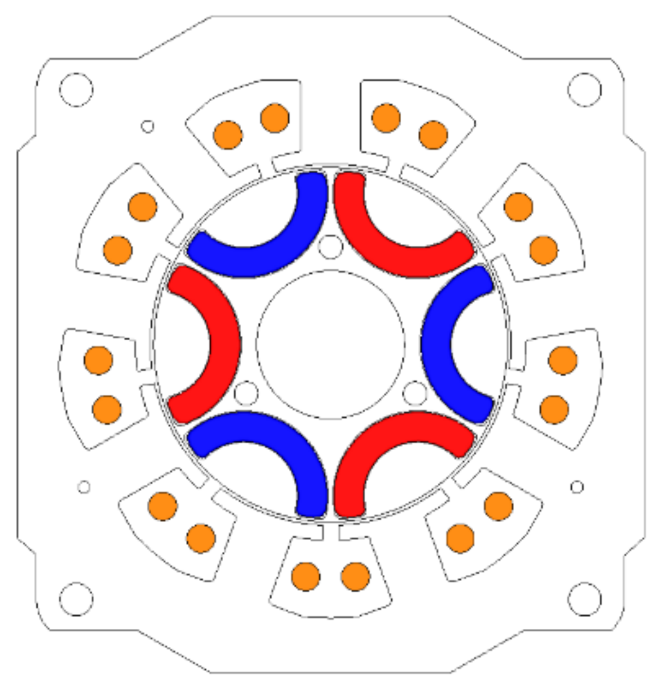
In order to design a BLDC motor with a dual rotor structure, a PM BLDC motor with one rotor as shown in
Figure 1 was selected as a model to be compared. This PM BLDC motor has a permanent magnet inserted into the rotor and consists of one stator and one rotor. Detailed specifications are shown in
Table 1. The BLDC motor operates in a 120-degree commutation mode. The stator has a rectangular structure. Before realizing miniaturization through the dual rotor structure proposed in this paper, a simple size can be selected by first obtaining the torque per rotor volume (TRV).
TRV is calculated as the internal rotor volume based on the arc of the center of the air gap between the stator and the rotor. The BLDC motor with a dual rotor structure consists of an outer rotor, an inner rotor, and a middle stator. Each rotor rotating around the middle stator generates a respective torque, and the sum of these two torques is the torque capacity of the motor. The dual rotor structure described in this paper is designed with a torque ratio of four by an external rotor and a torque ratio of one by an internal rotor. TRV can be distributed for each rotor. For each rotor, the torque is reduced compared to the reference model, so miniaturization can be achieved. In a BLDC motor with a dual rotor, the limit on the diameter of the outermost rotor is the limit on the diameter of the stator of the existing model. When the dual rotor structure is adopted, the rotor limit value can be further increased, and the torque can be increased compared to the existing model. In other words, the torque density can be increased, and overall miniaturization can be achieved. As the basic design model proposed in this paper, the stacking length was reduced by 50% to 16 mm, and the rotor diameter was increased to 62 mm.
Table 2 shows the values of TRV for two rotors distributed with a 1:4 torque ratio, and the torque per volume based on the outer diameter of the stator for the purpose of determining miniaturization. It can be seen that the stator standard torque density increased by about 1.9 times, and the total sum based on the rotor TRV also increased by 1.9 times. That is, it can be seen that miniaturization is achieved as a whole.
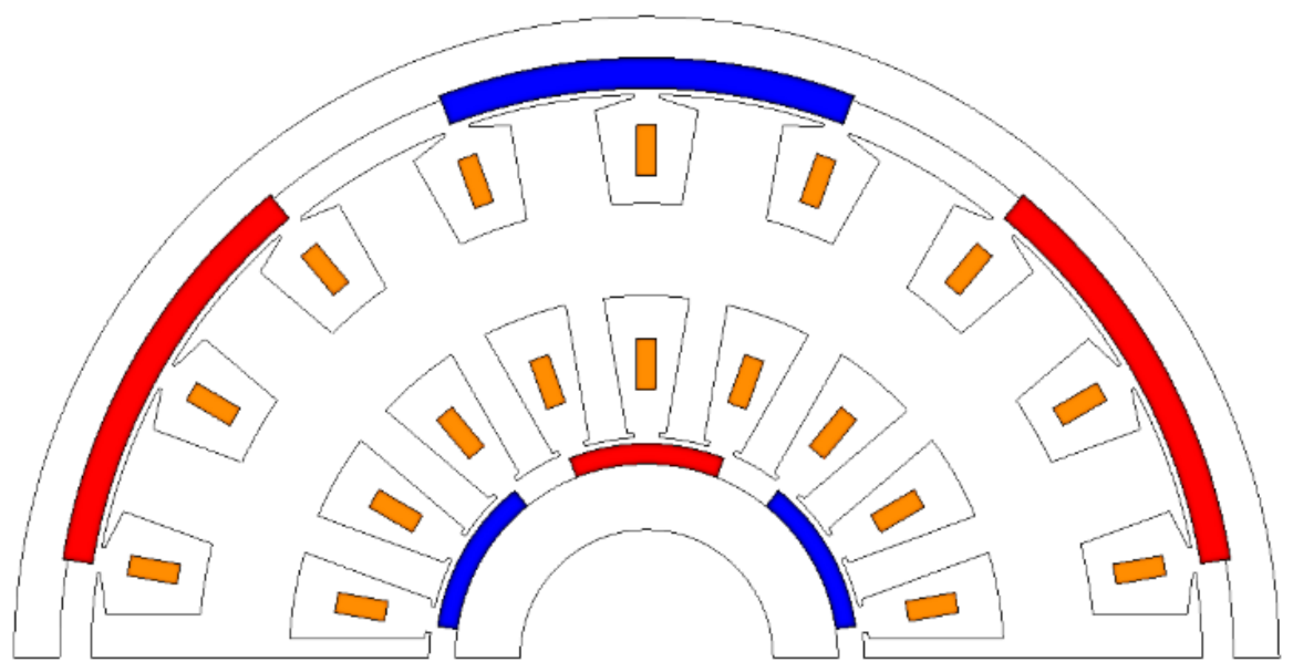
Figure 2 shows a simple dual rotor motor half model. After selecting the approximate size using TRV, the winding design is required. The winding structure of a dual rotor motor generally adopts a toroidal method. The winding is wound around the yoke of the stator. The general toroidal winding method was chosen because the winding operation is easy, controllability is excellent, and it has relatively high efficiency compared to other winding methods. However, the number of pole slots is limited. The occurrence of three-phase imbalance adversely affects the motor characteristics. In this paper, we confirmed the induced electromotive force generated in the winding according to the combination of the number of poles through simulation. The no-load simulation was performed without applying current, and the most balanced back EMF waveform was derived from the six-pole 18-slot combination.
The design of the pole-arc of a permanent magnet type motor is one of the most important factors. This is because the magnet of the rotor affects the back EMF waveform of the winding. The back electromotive force waveform has an important influence on the motor characteristics, depending on the control method. In the case of the 120-degree commutation method, the square wave waveform identical to the current waveform is the most ideal for the back EMF waveform, and in this case, the theoretical output and torque ripple are the least. On the other hand, in the case of the 180-degree commutation method, it is ideal to represent the back electromotive force waveform as a sine wave similar to the current waveform [
14,
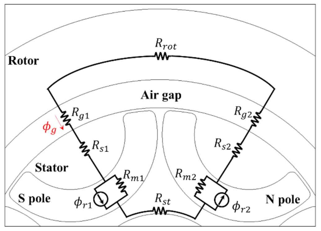
15]. In other words, it is necessary to select the pole-arc of the magnet that affects the back EMF waveform. The back EMF waveform is derived using finite element analysis. In this paper, the design is carried out using a 120-degree commutation method. The pole is selected by the magnetic equivalent circuit proposed in
Figure 3 and
Figure 4.
The key variables in the magnetic equivalent circuit are the residual magnetic flux of the magnet, the reluctance of the magnet itself, and the magnetic flux of the airgap. In addition, the reluctance variables of the core are negligible in constructing a magnetic equivalent circuit because the material of the electrical steel sheet used in the motor has low core loss and a very large reluctance in the airgap area. It was verified through direct calculation that the reluctance effect of the core was very insignificant in constructing the magnetic equivalent circuit. In other words, by assuming the reluctance of core to be 0, the magnetic equivalent circuit can be easily constructed to obtain a useful amount of magnetic flux. In
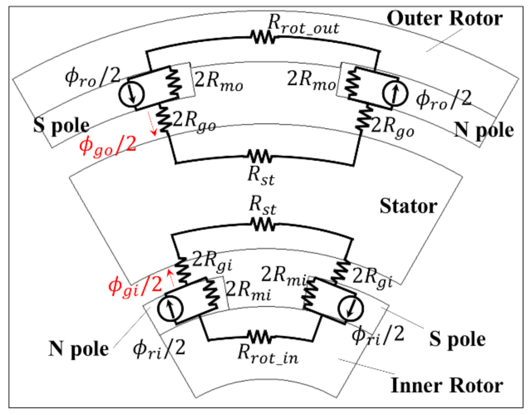
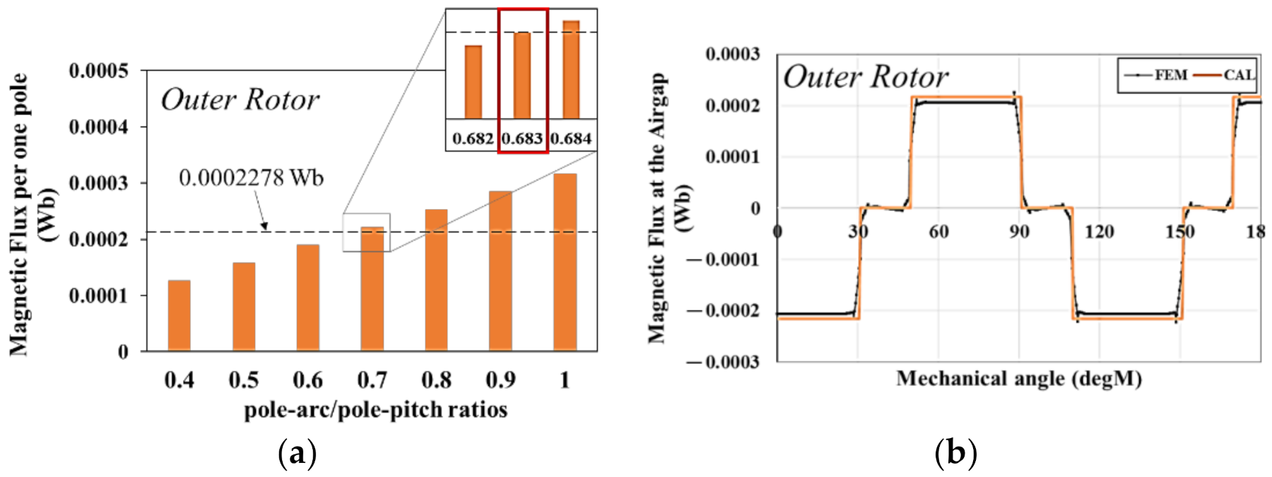
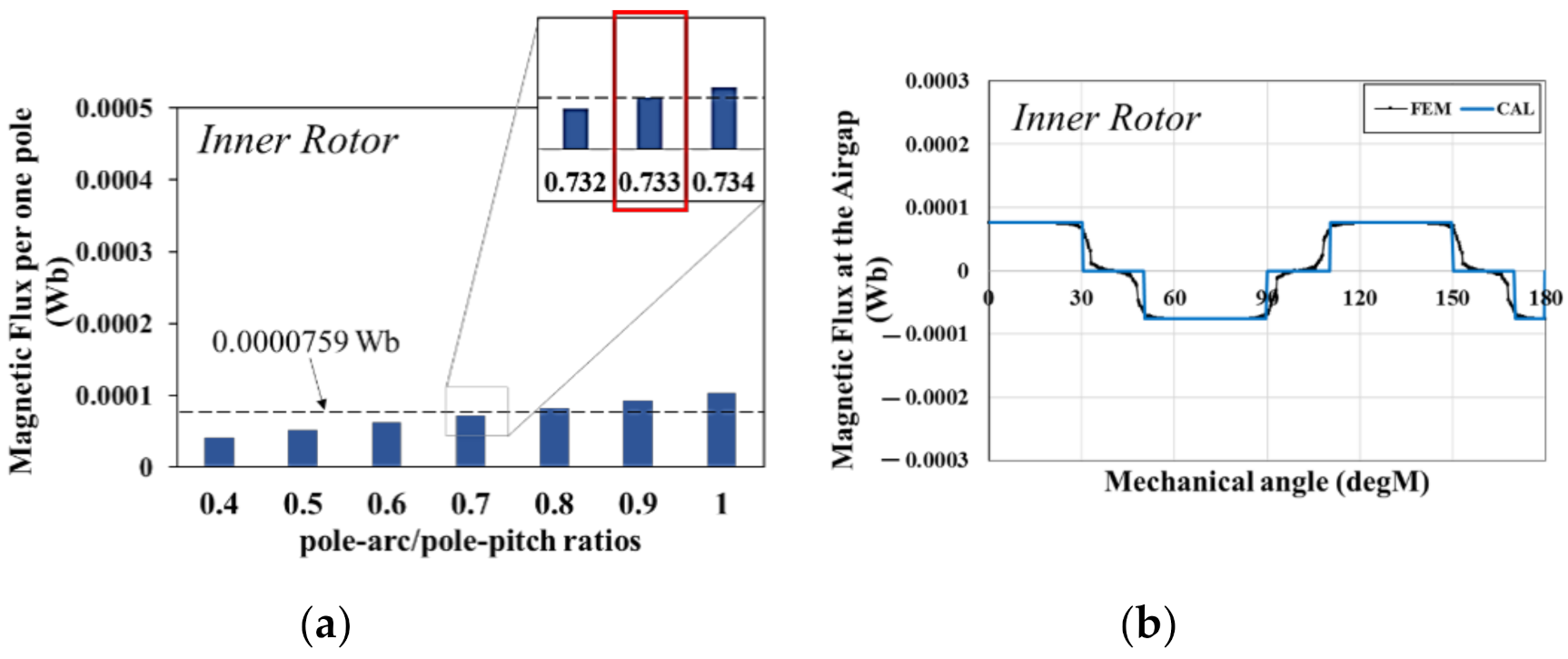
Figure 3, which shows the magnetic equivalent circuit of the existing model, the magnetic flux of the airgap is calculated to be about 0.0003037 Wb. When the torque ratio is designed as 1:4 and magnets such as airgap are used, the amount of magnetic flux distributed to the outer rotor and the inner rotor can be estimated to be about 0.0002278 Wb and 0.0000759 Wb, respectively. Through this distributed magnetic flux, the pole-arc can be selected using Equations (1) and (2) derived from the magnetic equivalent circuit of
Figure 4; α is the pole-arc/pole-pitch ratio, L is the stacking length, Np is the number of poles, and r is the radius of the part to be calculated. Equation (1) can be used to calculate other parameters such as the magnet and airgap reluctance. Equation (2) can obtain the magnetic flux per pole for a simpler magnetic equivalent circuit;
Φr is the magnetic flux of the magnet. This can be used to select the pole-arc.
Figure 5 and
Figure 6 show the comparison of the magnetic flux calculated by the magnetic equivalent circuit according to the pole-arc/pole-pitch ratio for the external and internal rotors, and the magnetic flux using the electromagnetic field finite element analysis method (FEM).
Figure 5a shows the magnetic flux amount of one pole according to the pole-arc/pole-pitch ratio for the external rotor. In order to reach the required magnetic flux in the external rotor, a ratio of 0.683 is required, which means that the pole-arc is 41 degrees.
Figure 5b is the verification compared with the FEM analysis. It can be confirmed that the magnetic flux generated by the pole-arc derived by the magnetic equivalent circuit and the FEM analysis result agree well. Similarly, in
Figure 6a, a ratio of 0.733 is required, which means that the pole-arc is 44 degrees. In
Figure 6b, it can be confirmed that the results of the FEM analysis match well.
3. Analysis on the Efficiency Improvement of the BLDC Motor Using a Dual Rotor
In the previous session, we selected and designed an appropriate pole-arc to pole-pitch ratio of a BLDC motor with a dual rotor through a magnetic equivalent circuit. After that, research on improving the efficiency of the motor is required. In general, the BLDC control method selects a 120-degree operation. It is selected because it is a simple ON/OFF operation with low switching loss, but it causes a large torque ripple, which causes the efficiency to decrease. In this paper, to improve the efficiency, we analyze the motor design aspect. In general, the motor operates due to an armature reaction between the magnetic flux generated by the current of the stator and the magnetic flux generated by the magnet of the rotor. In this paper, we discuss a design that generates optimal efficiency by reducing the core loss in the stator by using the experimental design method. In order to make a complementary design, the areas where the influence of the core loss is large are identified through a core loss separation analysis. Rotor losses are ignored. This is because the rotor experiences a DC magnetic field, so the core loss is not large. The core loss is caused by the change in magnetic flux density over time, and the effect of the core loss can be understood by observing the magnetic flux density saturation. Since the permanent magnet is located on the external rotor, there are many magnetic fluxes generated by this magnet. In other words, it is expected that much core loss will occur in the external rotor teeth.
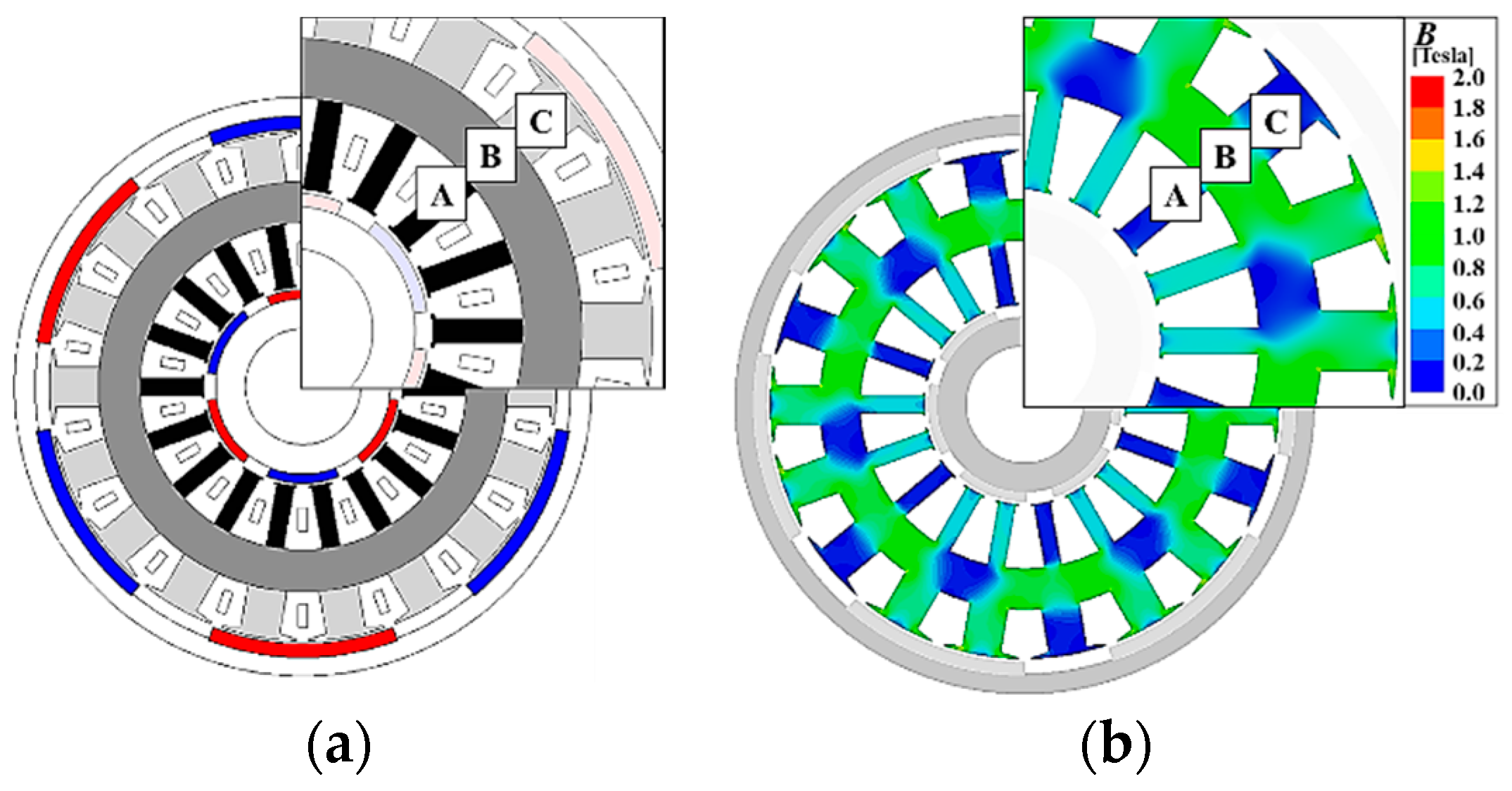
Figure 7 shows the analysis of core loss separation. For the analysis of core loss separation, it shows the separation in three stages, as shown in
Figure 7a. As expected, the magnetic flux density on the outer tooth or yoke side is high, as shown in
Figure 7b. That is, it is advantageous to increase the width of the external stator teeth and the width of the yoke in order to achieve efficiency improvement through reduction of core loss.
Table 3 shows the analysis results of core loss separation.
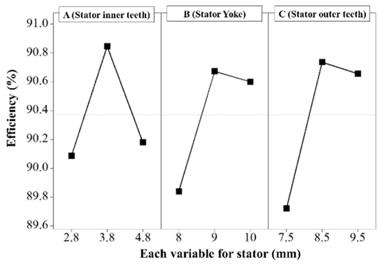
The core loss is large in the yoke area and the outer rotor tooth side. Now, with the results of the core loss separation analysis, the design of stator teeth, width, and yoke proceeds with the design for the smallest core loss through the experimental design method, as shown in
Figure 8. It is designed in detail by checking the point where the maximum efficiency comes out according to the tooth and yoke width.
4. Comparison of Experimental Results and Operation Mode
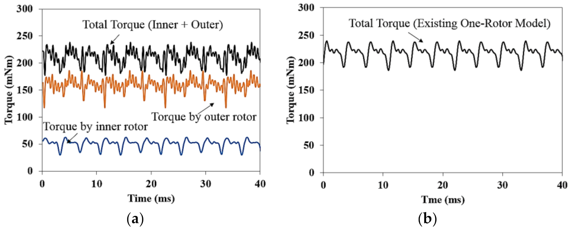
Figure 9 is a comparison of the torque waveforms of the BLDC motor with a dual rotor structure and the conventional one rotor structure, through simulation.
Figure 9a shows the torque waveform for the dual rotor type BLDC motor, which was designed in detail through the experimental design method after selecting the best ratio of the magnet with the magnetic equivalent circuit. The torque generated by the internal rotor is 52.84 mNm, and the torque generated by the external rotor is 167.7 mNm, and the sum of the total torque is 220.54 mNm.
Figure 9b shows the torque waveform of a BLDC motor with one rotor structure applied. It can be seen that it generates the same torque with a slight error of 2 mNm. Through this, it is verified that it achieved a reduction in volume of 45.6% compared to the existing model.
Figure 10 is a waveform comparing the back EMF between the no-load lines derived through simulation and experiment when the external and internal rotors simultaneously rotate at 1000 rpm.
Figure 10a is the waveform of the no-load back EMF derived at 1000 rpm through the test, which is 56.66 Vrms, and
Figure 10b shows the no-load back EMF waveform with 58.64 Vrms derived from the BLDC motor design based on the self-equivalent circuit. It is well-designed, showing an error rate of 3.38%.
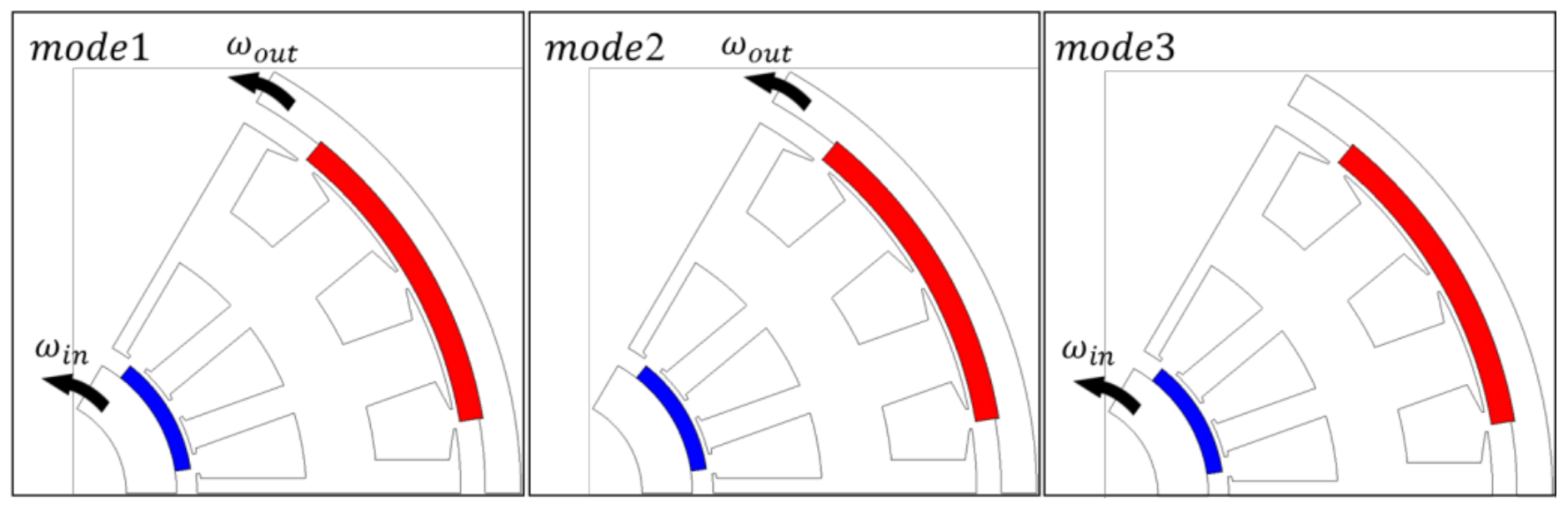
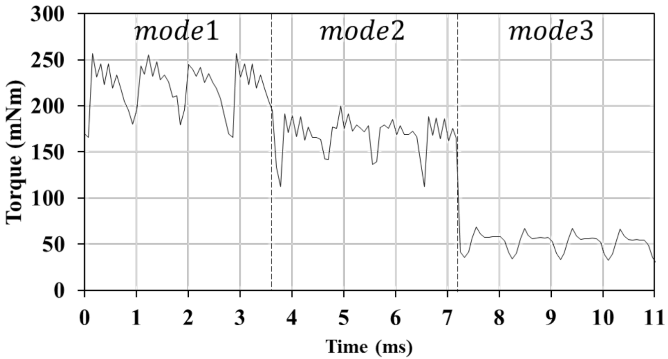
Figure 11 shows the three operation modes by adopting the dual rotor structure, which can change various speeds through outer and inner rotor control. Due to its dual rotor structure, it consists of an outer shaft mechanically connected to the outer rotor and an inner shaft mechanically connected to the inner rotor. These two shafts are coaxial. When two axes rotate at the same time, high torque can be generated, and when only one axis rotates, low torque is generated. Mode 1 can generate high torque at low speed because the external and internal rotors rotate simultaneously. Mode 2 only operates the external rotor. The torque decreases, and the back electromotive force decreases. Since there is room for back electromotive force, the speed can be further increased. Mode 3 drives only the internal rotor. The torque is the lowest, and the back electromotive force is very low. Since there is much room, the speed can be increased even more.
Table 4 shows the maximum speed and torque values that can be achieved within the limit of back EMF for each mode 215.6 Vrms, and the torque waveform for each mode over time is shown in
Figure 12.


