Review

Flow Inside the Sidewall Gaps of Hydraulic Machines: A Review

Victor Kaplan Department of Fluid Engineering, Faculty of Mechanical Engineering, Brno University of Technology, Technická 2896/2, 616 69 Brno, Czech Republic
*
Author to whom correspondence should be addressed.
Energies 2020, 13(24), 6617; https://doi.org/10.3390/en13246617
Submission received: 6 November 2020 / Revised: 30 November 2020 / Accepted: 2 December 2020 / Published: 15 December 2020

Abstract

:
The paper critically reviews the current state of the art in flow inside sidewall gaps of hydraulic pumps and turbines. It describes the consequences of the presence of this type of flow in turbomachinery and then relates it to other physical phenomena that determine the behavior, operating characteristics, and overall performance of the machine. Despite the small dimensions of the rotor-stator spaces, the flow in these regions can significantly affect the overall flow field and, consequently, efficiency. The circulation of the fluid inside the gaps and secondary flow that is caused by rotating elements influences the disk friction losses, which is of great importance, especially in the case of low specific speed pumps and turbines. The flow pattern affects the pressure distribution inside a machine and, thus, generates axial thrust. The presence of secondary flow also significantly changes the rotordynamics and can bring about undesirable vibrations and acoustics issues. This article aims to review and summarize the studies that were conducted on the mentioned phenomena. Experimental and numerical studies are both taken into consideration. It proposes some requirements for prospective research in order to fill current gaps in the literature and reveals the upcoming challenges in the design of hydraulic machines.

1. Introduction

Although the sidewall gaps are very tiny and, also, the volume of the fluid in these domains is orders of magnitude smaller when compared to the other dimensions of a pump or a turbine; the nature of the flow there can have a huge impact on the flow in the machine in general. In addition, the solution of the flow near rotating objects is not a trivial task and it has drawn the attention of researchers in the past for its relevance to many, but not only, industrial problems.
The first publication that aimed at the flow near rotating disk was from the oceanography that was issued in 1905 by Ekman [1] and it focused on the impact of the rotation of the Earth on wind-driven ocean currents. He was followed by Von Kármán [2] and Bödewadt [3]. Different variations of the problem, including rotating disk in stationary fluid, stationary disk in rotating fluid, and rotating disk in the rotating fluid, were studied. The authors described specific types of boundary layers that developed under the particular conditions and, thus, they have been named after them: Von Kármán boundary layer, Bödewadt boundary layer, and Ekman boundary layer. A solution of Navier–Stokes equations for described flows was proposed and further extensively studied both numerically and experimentally, e.g., in [4,5,6,7]. Later on, configurations with finite dimensions were introduced in order to bring theoretical studies closer to industrial applications.
With the growing knowledge in the area of fluid mechanics as well as in turbomachinery, it became clear that solving the flow in the sidewall gaps is not a trivial task. The geometry of the gaps in pumps and turbines is usually not as simple as in reported research studies. Moreover, it is complicated by the presence of throughflow, which is not negligible, since it has several consequences in various related phenomena. The most important issues directly governed by flow inside the sidewall gaps in hydraulic machines are disk friction, axial thrust, and problems that are connected to rotordynamics.
The structure of the paper follows the outlined topics. Section 1 describes the flow inside sidewall gaps of hydraulic machines in general. The phenomena that result from its presence are analyzed in the Section 2. Section 3 provides an overview of the improvement measures.

2. Flow Inside the Sidewall Gaps

2.1. Sidewall Gaps of Hydraulic Machines

Sidewall gaps are the spaces between the rotor and stator of the machine located in front of the rotor shrouds. Figure 1 shows it on the centrifugal pump and Francis turbine.
Axial clearances between the shrouds of a closed impeller and the casing are required due to mechanical design. Their size and shapes differ among hydraulic machines, as is given by aspects of the mechanical design, standardization of particular components, manufacturing, and material costs.
According to Li [10], the ratio of mean width of the gap to the outer radius of the impeller is commonly about 0.09, which enables manufacturers to accommodate the casing with different impeller sizes. Gülich [8] suggests keeping the ratio between 0.03–0.08. Large volumes of fluid should be avoided due to increased turbulent dissipation and, therefore, increased disk friction losses. It is advised to eliminate complex contours and shapes, such as ribs, which slow down the rotation of the fluid. It is sometimes a trade-off between the disk friction losses and axial thrust. The casing of the volute should be designed in a way that the fluid of low velocity flowing from the volute into the sidewall gap does not interfere with the pumping action of the shrouds. The fluid from the boundary layers of the impeller has to be allowed to transfer its energy to the main flow. Wide impeller sidewall gaps open to the volute should be, in general, avoided in high energy pumps. The gaps should also be designed concerning possible additional elements of the impeller e.g., for axial force balancing. Auxiliary vanes on the shrouds increase the rotation of the fluid inside sidewall gaps, whilst balance holes make flow conditions in the back sidewall gap more similar to the front one.
In the case of the turbine, the sidewall gaps should be designed specially in order to ensure the proper function of the labyrinth seals. The seal consists of two parts, a static seal connected to the stationary cover and a rotating part connected to the runner. The counterparts fit together in a crested manner where wider and narrower channels take turns to lower the fluid velocity. The gaps are forced to be as narrow as possible since they influence the volumetric efficiency of the turbine. In turbines for low heads, the gaps are machined into the material of the runner and, in these cases, clearances are usually about 1–2 mm. For larger heads and machines, the gaps parts are made of bronze or stainless steel and the clearances are even smaller. As the seals wear, the gap width increases and, consequently, the leakage increases as well [11].
Practical demonstrations regardinf how the clearance influences performance and efficiency of hydraulic machines can be found in [12,13,14]. Aly et al. [12] proved the trend of how the characteristic of the centrifugal pump is shifted for different values of clearances. With increasing side clearance, the head and efficiency decreases and the optimum are in lower flow rates, as can be seen in Figure 2.
Special attention has to be paid to the design of the clearances in hydraulic machines that can operate as pumps as well as turbines (reversible Francis turbines and pump-as-turbine = PAT), as describes [14]. The shape and width of wear-ring clearance not only affect the volumetric efficiency, but also affect the main flow of the impeller, which influences the performance of the pump-turbine significantly. The design of sealing also plays an important role in overall efficiency. Yan et al. [14] studied the differences between the performance when the sidewall gaps of PAT are closed with labyrinth seals or flat ring seal. Different clearances were also taken into consideration. Variations in efficiency characteristics were observed in both pump and turbine modes. With increasing clearance, the efficiency decreases, no matter whether the machine works as a pump or a turbine. It is in agreement with [12,13]. The performance of the labyrinth seal is generally better than with the flat ring seal.
From the design point of view, the strong influence of the gaps on the dynamics of the rotor has to be kept in mind. Surface-to-surface contact between the stationary and rotating parts of the seals may induce damping and significantly lower the natural frequency [15].

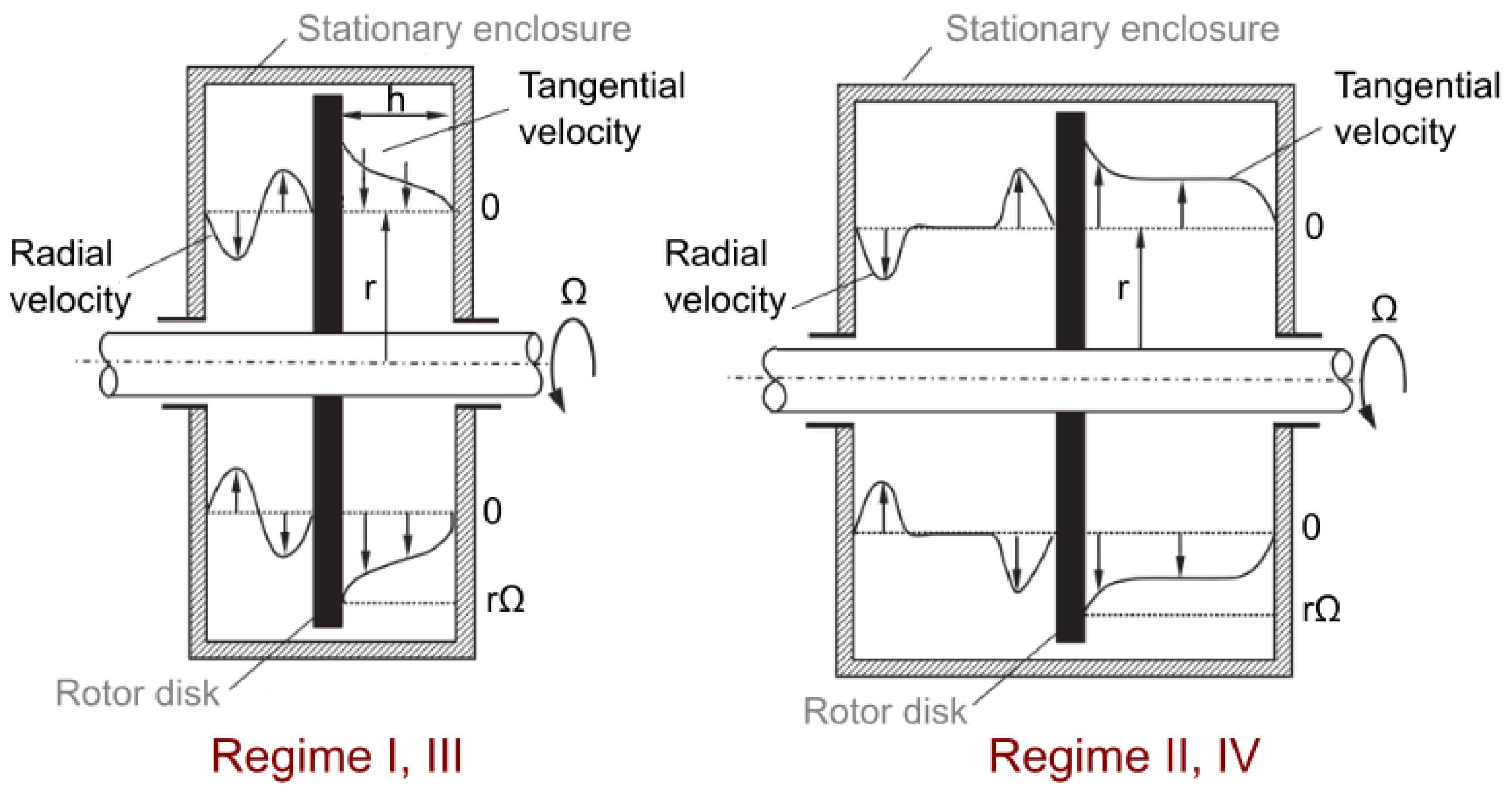
2.2. Flow Regimes and Patterns in Rotor-Stator Cavity

Flow near rotating disks in the stationary infinite fluid was first theoretically studied for its relevance to meteorology. The theories became applied to enclosed disk in the interest of understanding phenomena occurring in hydraulic machines. With the growth in demands on the performance and efficiency of pumps and turbines, the need for understanding the topic arose. Daily and Nece [16] first studied the problem of the flow in enclosed cavities while using an experimental apparatus designed specifically for this purpose and introduced variables used to analyze this type of flow, see Figure 3. They find out that there exist four different flow regimes that are dependent on the dimensions of the cavity and operating conditions. It can be expressed by means of non-dimensional variables: aspect ratio G and rotational Reynolds number R e defined, as follows:
G = h / b ,
where h is the width of the gap and b is the outer radius, as shows Figure 3
R e = v · v ν Δ v = U L ν = Ω b 2 ν ,
where L is a typical length scale (in the case of enclosed cavity outer radius ), U circumferential velocity, Ω is angular velocity, and ν is kinematic viscosity of the fluid.
The combination of G and R e governs, which, of four possible flow regimes, occurs in the rotating cavity, see Figure 4. The flow can be either laminar or turbulent and merged or separated boundary layers on stationary and rotating disks can be observed, as illustrated in Figure 5. The following combinations are theoretically possible; however, for a given geometry and range of operating conditions, it does not have to be feasible to obtain all of them.
  • regime I (laminar flow, merged boundary layers);
  • regime II (laminar flow, separate boundary layers);
  • regime III (turbulent flow, merged boundary layers);
  • regime VI (turbulent flow, separate boundary layers).
Besides these four essential regimes, there are many unstable structures, which typically emerge on transitions between regimes. Smith [19] first noticed the instabilities in the flow near the rotating disk, who observed fluctuations appearing in a narrow range of R e , which produce sinusoidal waves excited by random disturbances. Kohama [20] visualized the structures that were generated in the boundary layer while using titanium tetrachloride and multi strobe light. It is visible in the form of spiral-shaped vortices propagating rapidly radially outwards from the rotational axis. The discovered instability is referred to as Type 1, Type B, or crossflow instability. Faller and Kaylor [21] reported the existence of the second type of instability developing for lower values of R e , which is denoted Type 2 or Type A. It is also observable as spiral waves; however, it has an opposite angle to Type B and it is characterized by relatively small values of wave speed. Circular waves in the Bödewadt boundary layer were reported by Savas [22] and other structures emerged in enclosed cavities due to the effects of finite dimensions, as described by Brady and Durlofsky [23].
The mechanisms of origin are discussed in [24] and they were supported by many numerical studies [21,25,26,27]. With development of experimental techniques, other types of instabilities were discovered, as shown in Figure 6. The authors reported new findings for laminar regimes [28,29,30]; however, due to an industrial application point of view, turbulent regimes were of a greater interest, as evidenced by numerous studies [28,31,32,33,34,35,36]. A comprehensive summary of instabilities offers the experimental research that was performed by Schouvelier et al.
Aiming at particular applications, many extension studies were published, e.g., Soong et al. [37] dealt with the influence of edges, other authors studied the effect of surface roughness [38,39], the porosity of the disk [40], or how the disk deformation possibly affects the flow [41,42]. The flow of non-Newtonian fluids over the rotating disks is discussed in [43,44,45], the solution of the flow coupled with heat transfer was presented in [46,47,48], and publications [49,50,51] consider the presence of electromagnetic field and its impact on the flow.
For its relevance to turbomachinery, the effect of throughflow was addresed by a few authors [52,53,54,55]. Hide [52] derived approximate analytical solution for laminar flow supported by experiments that suggest that the basic steady flow is axisymmetric and also symmetric with respect to the middle height of the cavity. The core flow can be described as geostrophic and its strength is related to the mass flow rate of the throughflow. Even a slight increase in the mass flow rate leads to the occurrence of instabilities. It was studied by Owen and Pincombe [53] in more detail, the theory [52] was slightly modified and expanded for the turbulent flow. They carried out a series of experimental measurements with flow visualization, which revealed that, with increasing flow rate, the extent of the central core flow region grows and, consequently, the depth of the Ekman boundary layer decreases. It supports the earlier formation of instabilities. The influence of the direction (whether the fluid enters the cavity axially or radially), as illustrated in Figure 7, was discussed. It was found out that the main difference is in the size and nature of the flow in the immediate vicinity of the inlet. For the radial inlet case, with increasing R e , the flow was destabilized by large-scale instabilities occurring as a consequence of Ekman layer onset. On the contrary, the presence of axial inlet gives rise to recirculating flow and the occurrence of Ekman layer instability and/or vortex breakdown in the central jet caused unsteady flow, regardless of the value of R e , under all of the observed conditions.
Crespo et al. [54] studied the exact mechanisms of the origin of the instabilities in rotating cavity with throughflow. For weakly forced throughflow, the flow in the cavity is steady, however, an increase in mass flow rate leads to a chaotic temporal behavior through several bifurcations perturbing the basic spatial configuration of the flow. First, the symmetry with respect to the midheight of the cavity is broken. Wavy motions start at the inlet region and then move alternately towards the top and bottom Ekman layers, in spite of that the boundary layers are not disturbed. With increasing flow rate, the periodic oscillatory instability is gradually developed with vortices along with the Ekman boundary layers and horizontal waves in the core regions well. The frequency of oscillations is close to the rotation rate frequency of the cavity. With a further increase of mass flow rate, the flow undergoes a transition to quasiperiodicity that is characterized by larger amplitudes and shorter wavelength. Subsequently, other periodic behavior occurs before the final transition to chaotic flow. The study has a major limitation, since it only covers an axisymmetric solution and, thus, instabilities with non-axisymmetric nature do not have to be detected.
A three-dimensional solution was reported later in [55] and it supported previous findings. The first developed instability is in form of pairs of counter-rotating axisymmetric rolls traveling radially outward in the Ekman layer, see Figure 8 top. It was found out that the instabilities are mainly located at the border between the Ekman layer and the geostrophic core. It was proved that the second instability is not axisymmetric and it can be observed as a set of spirals, as can be seen in Figure 8, bottom. The number of spiral arms depends on the curvature (ratio between inner and outer radius) of the cavity. It was also found out that, once formed, both of the instabilities remain stable to further disturbances.
The flow in sidewall gaps of hydraulic machines itself is quite complex, due to its geometry as well as because of established conditions. The most common applications in hydropower or pumping are designed to operate in the turbulent regime with separate boundary layers (regime IV). However, regime III was also reported in [56] and laminar regimes in pump for oil with high viscosity were studied by Li [10].
The flow direction radially outwards is developed due to the centrifugal forces in the rotating boundary layer. As a consequence of continuity, fluid flows back radially inwards along the casing wall. It means that the flow can be described as circulating in the meridional section with dominating circumferential components over the radial. However, the presence of different regimes and instabilities is always possible, as outlined in Section 1 and it was captured by CFD in [57]. This is more likely in the sidewall gap with leakage. The effect of the leakage flow is much stronger in the front impeller side clearances when compared to the rear impeller side clearances.
Will et al. [56] describe that the fundamental difference can be observed in the radial evolution of the pressure. For the back sidewall gap with weak leakage flow, there is a non-negligible axial velocity across the gap. It is related to uneven velocity directions for different tangential positions. These phenomena were reported in few publications [56,57,58] and are illustrated in Figure 9. A region with low static pressure is developed after the cutwater due to the asymmetry of the volute casing. The fluid is accelerated in a tangential direction that cannot be counterbalanced by a radial pressure force; therefore, recirculation develops. Subsequently, the fluid is centrifuged out of the cavity into the volute and mixed with the main flow. Before the cutwater, on the contrary, the fluid is sucked into the sidewall gap as a result of the pressure gradient in the radial direction. Moreover, the flow field evolves in time and it is also governed by the position of rotor channels, as outlined Su et al. [58]. On the contrary, the flow field in the front sidewall gap is mostly governed by the presence of inward-directed throughflow.
Wu et al. [59] dealt with the flow in the front sidewall chamber, where leakage plays an important role. Similar asymmetric effects were observed and they are shown in Figure 10. It can be seen that the uneven effects are not so strong for BEP and are more pronounced in off-design conditions. It was also found out that the secondary flow leaking from the front sidewall gap is a significant source of vorticity. It affects the mainstream at the impeller inlet and it is a source of energy loss.
Although the sidewall flow seems to be, to some extent, separated from the main flow field in the hydraulic machine, it turns out that this is not an entirely correct assumption. Despite that most of the numerical analyses completely neglect the sidewall gaps geometry, some authors [9,13,59,60,61,62] showed that the flow in the sidewall gaps can have a great impact on the whole flow pattern and calculated efficiency [63,64,65].
Čelič and Ondračka [63] quantified the difference between CFD taking into consideration sidewall gaps in the case of Francis turbine and reported an acceptable 3% difference for BEP; however, in off-design conditions the discrepancies rise dramatically. According to Feng et al. [66], the error due to neglecting disk friction in the CFD model of Francis turbine is about 10%. Losses related to sidewall gaps flow are the most pronounced while operating at low specific speed as demonstrates Figure 11. Significant discrepancies in 5h3 computed efficiency while neglecting sidewall flow in the same turbine were also by described Jošt et al. [64] and Mössinger et al. [65]. They also discussed the high computational costs of CFD simulations, including sidewall domains, and suggested alternative approaches in order to obtain a reliable value of efficiency.
Casartelli et al. [67] showed that, for the computation of global characteristic (head and efficiency) in the Francis turbine, it can be a reasonable assumption to neglect the sidewall gap; however, the interaction of the two flows influence the near-wall region considerably. The computation taking into consideration sidewall space results in a completely different flow pattern, which can be crucial for the correct determination of the flow field in the draft tube. These local flow patterns, due to the presence of sidewall inflow, are advected and they persist downstream affecting the boundary layer behavior. Therefore, components of the flow entering the draft tube differ between the cases with and without the inclusion of the sidewall gap flow. As the diffusing flows, such as those found in draft tubes, are very sensitive to inlet conditions, it can be a potential source of errors in computations.
The authors [68] studied how the calculation of the flow in the draft tube is influenced by neglecting the flow from side gaps for BEP and also for off-design operating conditions: part-load (PL) and high load (HL). There were slight discrepancies between the cases with and without sidewall inflow at part-load. Unsteady behavior was observed for both calculations; however, there was a lower rise of the pressure between inlet and outlet for the case with leakage flow. Additionally, amplitudes of the pressure fluctuations that were caused by unsteady swirl were lower by 16%, which suggests the damping effect of the mixing process in the near-wall region due to the leakage inflow. The biggest inconsistency was observed for BEP, where the character of the flow completely differed due to the presence of sidewall gap flow. The simulation without leakage flow was unsteady, whilst the second case was steady, probably, again, as a result of increased damping and loss generation connected with the presence of side inflow. Steady results were obtained at HL for both cases; nevertheless, in contrast to the PL, the rise of the pressure for the case with side inflow was higher. The differences in the flow field at BEP are demonstrated in Figure 12. In both cases, the backflow zone in the elbow region of the draft tube was found; however, the extension is different. It is larger for the case without sidewall gap inflow and begins further upstream. On the contrary, the area of recirculation in the axial direction is to a larger extent for the case with gap inflow.
Feng et al. [66] observed that even the leakage through the crown seal gap propagates downstream in a way that can influence the flow in the draft tube. The meridional velocity near the crown is reduced due to the presence of throughflow and, as a consequence, the velocity gradient along with the blade height increases. It changes the inflow conditions for the draft tube and the flow pattern inside the draft tube.
Trivedi [9] performed CFD simulation while using the precise LES technique in the whole domain of Francis turbine, which revealed a complete breakdown of the boundary layer at the junction of the runner and the draft tube. It is a consequence of jet-type flow from the labyrinth (band) seal gap. The shear layer between the viscous and turbulent layers collapses causing the adverse pressure gradient. A distinct pattern of recirculating flow is then generated between the runner outlet and the elbow.
Aly et al. [12] demonstrated that the secondary vortex, which is created as a consequence of sidewall gap flow presence, can, in the case of a centrifugal pump with a semi-open impeller, strongly impede the core flow in the impeller. The width of the sidewall gap influences the pressure field near the connection to the main flow and, thus, can have an impact on the calculated efficiency of the pump.
Zhou et al. [62] studied the flow in sidewall gaps in Francis turbine during transient conditions. Measurements and CFD revealed strong pressure pulsations in labyrinth seals and, thus, the periodic variation of leakage flow as a result of a change of guide vanes angle. The authors also pointed out that the differences in computed pressure in the model that neglects the sidewall gaps domains were about 12%, whilst with the sidewall regions, the results match well with the measurements.
Gautam et al. [69] studied the erosion of Francis turbine in an inlet near hub-shroud region and towards the trailing edge of runner blade. They reported that it was due to vortices traveling from clearance gaps, hitting the inlet of the turbine runner, and leaving it with very high velocity.
Yan et al. [14] studied the differences between the flow when the sidewall gaps of pump-turbine are designed as labyrinth seals and flat ring seal. Different clearances were also taken into consideration. While operating in turbine mode, the outflow from the sidewall gap has the same direction as the main flow and, therefore, the influence is minor. On the contrary, as a pump, the mixing area gains importance. The labyrinth seals affect the main flow less, due to lower leakage flow through the seals than the flat wear ring. The same trend can be observed for the flat ring with smaller clearance.
The flow through sealing structures was the scope of a number of studies, e.g., [70,71,72,73,74,75,76]; however, it has to be pointed out that it should be always related to the overall flow field of the specific hydraulic machine.

3. Phenomena Connected with Flow in Turbomachines Sidewall Gaps

3.1. Disk Friction Losses
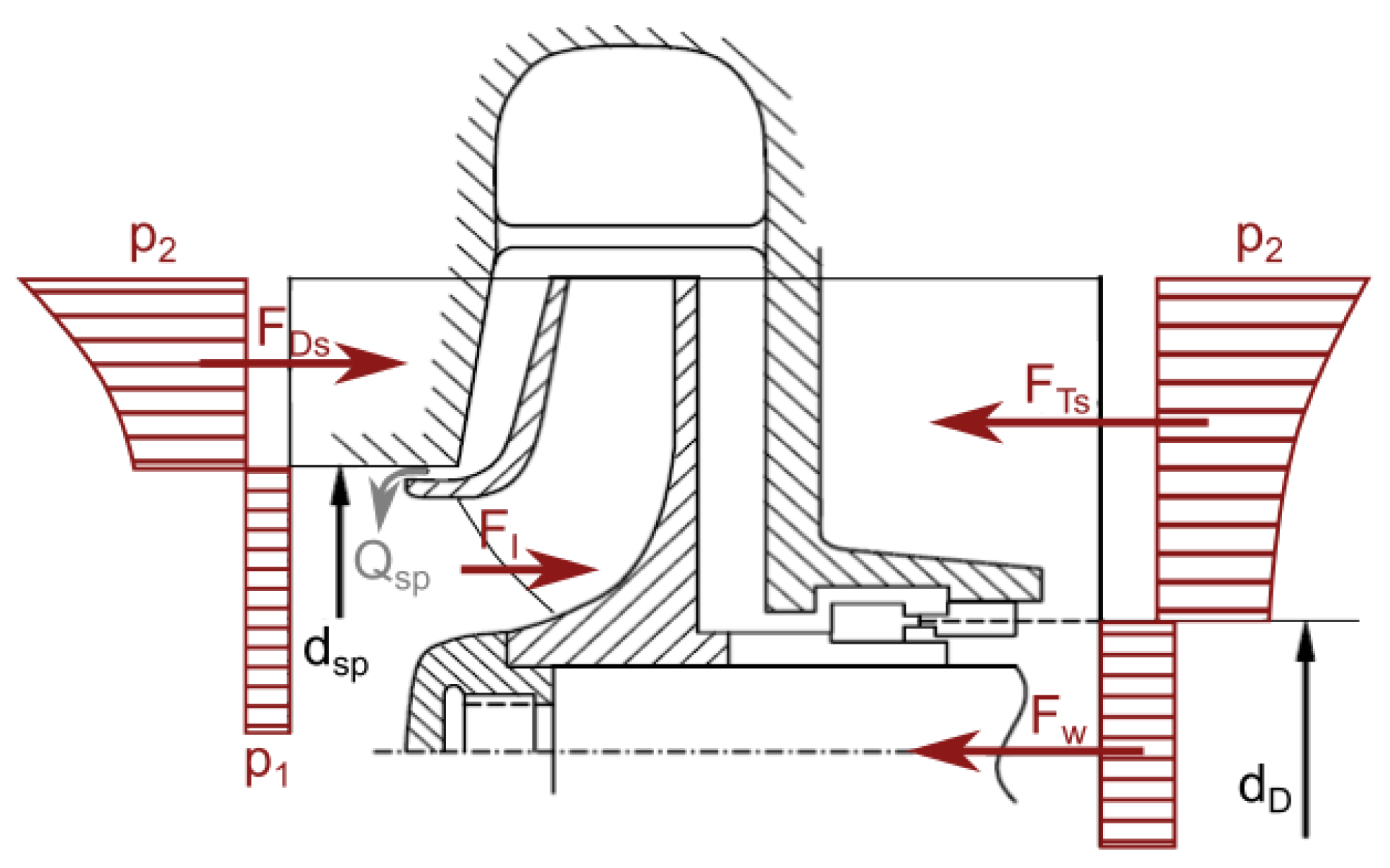
Disk friction losses are generated on a hub and a shroud of the impeller, which represents the rotating wall of sidewall cavities. It is caused by shear stress arising on the surfaces. It can influence the overall efficiency significantly, especially in the case of low specific speed hydraulic machines. The typical pump power losses due to disk friction typically reach about 50% of the useful power [77] in the case of specific speed n q = 10. Disk friction losses are also the most pronounced in very low specific speed turbines, moreover, it is strongly influenced by operating conditions. The losses gain importance in off-design conditions, especially at part-load, for which the flow rate is low and rotational speed is high [78]. Disk friction losses can increase rapidly during the lifetime if corrosion and/or sediment erosion are present. The drop of the efficiency as a consequence of disk friction due to enhanced erosion can amount to 50% [79].
Therefore, there is a strong need to have at least an estimation of the disk friction losses already during the design process of the machine.
The quantification of the disk friction was first investigated on a simplified case of the plain disk rotating in an enclosed cylindrical casing. The shear stress that corresponds to local friction coefficient c f generated on the surfaces of a rotating disk can be expressed as [8]:
τ = 1 2 ρ c f u 2 ,
where u is circumferential velocity:
u = ω r ,
friction force acting on the surface of the disk can be expressed as:
d F = 2 π τ r d r ,
torque that is caused by the friction is:
d M = r d F = π ρ c f ω 2 r 4 d r ,
and friction power on one side of the disk is then:
P R P = ω a b d M = π 5 ρ c f ω 3 b 5 1 a 5 b 5 .
If the disk rotates inside a casing, then this approach is not valid, since the velocity distribution between the casing and rotating disk depends on the gap between the disk surface and the casing wall, as well as on the boundary layers forming on the stationary and rotating surfaces. The velocity of core flow can be approximately expressed as [8]:
u = 1 2 ω r .
Therefore, the power that is consumed by the disk in the stationary casing can be estimated as half of the power of a free disk rotating in a stationary fluid.
Most of the studies that focused on disk friction losses took into account the simplified geometry of the disk rotating in a cylindrical casing. A few papers dealt with the topic theoretically by considering an amount of simplifying assumptions, trying to support it by some measurements [80,81]. A comprehensive study by Daily and Nece [82] aimed at influencing the geometry of the cavity and trying to relate the disk friction to the regime of flow in the disk sidewall gaps. They quantified disk friction while using the so-called moment coefficient, which, in their experimental setup, involves the flow regime effect and it appears in the equation for friction torque:
M = c m 1 2 ρ ω 2 b 5 .
The friction torque M was experimentally measured for different values of R e and, therefore, regimes IIV. Equations describing moment coefficient trends for particular regimes were derived:
c m I = 2 π ( s / b ) · R e ,
c m I I = 3.7 · ( s / b ) 1 10 R e 1 2 ,
c m I I I = 0.08 ( s / b ) 1 6 · R e 1 4 ,
c m I V = 0.0102 · ( s / b ) 1 10 R e 1 6 ,
where s is the axial gap between rotating and stationary disk and a is the outer radius of the cavity.
Nece and Daily expanded their research in order to study the influence of surface roughness [82]. It was found out, that for laminar flow (regime I and II) the roughness does not affect the friction torque, in other words, the measured characteristics were the same for the smooth and the rough disk. The situation is opposite in turbulent regimes (III and IV), where the influence of relative surface roughness b / k even dominates over the effect of axial gap width. In addition, it was found out that the roughness of the casing also influences the transition to turbulence and, consequently, the value of the moment coefficient. For a combination of rough disk and rough stator, the torque coefficient tends to be constant, regardless of R e , s / b , and b / k . On the contrary, for rough disk and smooth casing, c m does not stabilize on a constant value and is proportional to R e 1 / 10 . The moment coefficient for turbulent regimes (rough disk and rough enclosing wall) can be, according to experimental data, expressed as:
1 c m = 3.8 log b k 2.4 s b 1 / 4 ,
Poullikkas [83], in his study of roughness effects, confirmed the result obtained in [82] and offered a slightly modified form of the equation for the determination of c m . He also addressed the possibility of influence due to the presence of throughflow. Daily et al. [84] introduced the so-called throughflow parameter λ for the assessment of the importance of the throughflow over the rotational flow in the fluid core. Once the value of λ over 0.219 is reached, the flow becomes rotationally to radially dominated.
λ = C w R e 0.8 ,
where R e is rotational Reynolds number defined previously and C w is throughflow Reynolds number (sometimes also denoted as flow rate coefficient or throughflow coefficient), which can be expressed as:
C w = m ˙ μ · b = Q ν · b ,
where the characteristic dimension is the disk outer radius b, m ˙ is the mass flow rate through the system, μ is the dynamic viscosity of the fluid, Q is the volumetric flow rate, and ν is the kinematic viscosity of the fluid. With increasing throughflow, the boundary layers become compressed. Even though the tangential velocity in the stator boundary layer decreases, the gradient of tangential velocity that governs the shear stress in the rotor boundary layer becomes close to ω r , and the value of the moment coefficient increases.
Chew and Vaughan [85] made a correlation of the effect of throughflow on moment coefficient. Figure 13 shows the ratio of moment coefficient of the cavity with throughflow c m to moment coefficient of equivalent configuration with no throughflow c m 0 plotted against the throughflow parameter λ . Gärtner [86] derived an alternative equation that took throughflow into account.
Owen [87] studied the problem of the influence of the direction of the inflow (radial vs. axial, see Figure 14 on the value of moment coefficient numerically. They divided the fluid domain into two regions: the source, where the flow is strongly influenced by the inlet boundary condition, and the rest, unaffected. The equation for the estimation of moment coefficient then can be expressed as:
c m = 2 ( R e 0.2 0.0729 X c 23 5 + 0.0389 [ ( 1 X c 23 5 + 14.7 λ ( 1 X c 2 ) + 90.4 λ ( 1 X c 3 5 ) ) ] ) ,
where
X c = 1.79 λ 5 13
Aiming on turbomachinery applications, Hu et al. investigated the influence of flow direction (centripetal [17] vs centrifugal [88] flow), see Figure 14. They found out that, for centripetal flow, c m increases with C w , while it decreases with increasing R e . Moreover, for higher values of R e , the effect of throughflow becomes less significant. Exactly the same trend was also observed for centrifugal throughflow. However, it should be pointed out that centrifugal throughflow arrangement results in higher c m for the same value of C w .
Coren et al. [89], who offered an overall comparison of previously derived models, later systematically revised the topic. Based on a large amount of their own and previously published experimental data, a new equation covering the wide range of operating conditions (with and without throughflow at the same time) was acquired:
c m = 0.52 C w 0.37 R e 0.57 + 0.0028 .
The authors discuss, in detail, the problems of experimental data correlation. Although the empirical equations are based on the more or less same theoretical background, the obtained values, even for the same R e , strongly depend on the geometrical setup of the particular experimental apparatus used for the measurement. The best-achieved agreement while trying to reproduce previously performed experiments was about 10%. Other data differed more, which was mostly attributed to the difference in flow conditions that were given by designs of testing rigs.
A comprehensive overview of derived equations is given in Table 1. Empirical equations are summarized, along with the effects that they include. It can be seen that the studies were usually focused on one particular effect (e.g., throughflow or roughness) and although the importance of others was already known, the phenomena were treated separately. There is no complex equation covering all of the known influences. For practical use, it is always necessary to revise which of those equations was derived under similar conditions.
In addition, the applicability of those findings for real hydraulic machines is questionable. The majority of studies are based on ideal annular geometry and steady operating conditions, which is not true in turbomachinery. Years of development and optimization resulted in quite complex shapes of the sidewall gaps of pumps and the presence of various design features, such as labyrinth seals in turbines. Other difficulties are caused by the presence of throughflow and requirements for a wide range of operating conditions of current machines. There is still a need for fundamental research in order to understand all of the aspects of such a complex flow.
The authors who performed measurements with disks rotating in volute casings reported 40 to 70% higher losses than expected based on the estimations for a plain disk in a cylindrical casing [90].
Gülich [77] investigated the effects that are mainly given by real shapes that are used in turbomachinery, which significantly affect the disk friction. He derived the form of equations suitable for a geometry of a pump impeller, not only for simplified disk inside the cylindrical casing. The friction power can be calculated while using variables according to Figure 15.
For γ < 45 and R e > 10 , the friction power is [77]:
P R R = k R R cos γ ρ ω 3 r 2 5 1 r 1 r 2 5 ,
where k R R is friction coefficient determined experimentally, equivalent of c m for plain disks. The coefficient can be further expressed by the multiplication of terms that result from particular effects. A single formula for estimation of the friction coefficient valid for all flow regimes can be expressed as [77]:
k R R = π 2 R e s a x * + 0.0625 R e 0.2 ( 1 k o ) 1.75 f R , i m p f l ,
where s a x * is ratio of axial gap to impeller outer radius s a x * = s a x / r 2 , f R , i m p expresses the roughness effect, f l gives influence of leakage, and k o is rotation factor of the flow with zero leakage Q s p . The rotation factor is given by the ratio of fluid velocity to impeller circumferential velocity:
k = c u u .
For zero leakage, it is given as [77]:
k 0 = 1 1 + ( r w r 2 ) 2 · ( r w r 2 + 5 t a x r 2 ) c f , c a s e c f , i m p ,
where c f , c a s e and c f , i m p are the friction coefficients of casing wall and impeller. Factors taking into account surface roughness and leakage flow by influencing the value of friction coefficient are formulated as [77]:
f R , i m p = k R R ( ϵ ) k R R ( ϵ = 0 ) = log 12.5 R e log 0.2 ϵ r 2 + 12.5 R e 2.15 ,
where ϵ is equivalent sand roughness of impeller side.
f l = k R R ( Q s p ) k R R ( Q s p = 0 ) = e x p 350 φ s p r 2 r s p l 1 ,
where φ s p is leakage coefficient including direction of the leakage flow. If it aims radially inwards, φ s p is positive and l = 1 , if the direction is outwards, φ s p is negative and l = 0.75 . The value of the leakage coefficient can be calculated as [77]:
φ s p = Q s p π r 2 2 u 2 .
Numerous authors then studied the effects of individual variables appearing in the derived equations, which were detected as the most influential parameters. The character of the flow in turbomachinery is, in most cases, turbulent. When the flow becomes laminar, the coefficient of friction steeply rises. Nemdilli and Hellmann [91] experimentally proved that moment coefficient declines with increasing R e .
The share of disk friction losses in the power consumption of a pump decreases exponentially with increasing specific speed. In the case of low specific speeds, the disk friction is the main source of losses [77]. Mikhail et al. [92] carried out a series of experiments with centrifugal pumps, showing that the disk friction coefficient increases parabolically with increasing specific speed and decreases with increasing pump capacity, as can be seen in Figure 16.
The effect of axial clearance was described in [8] as significant in laminar regimes and minor in a turbulent flow. In cases of extremely narrow gaps where the clearance is smaller than the thickness of the boundary layers, the value of c m is very high, decreasing to its theoretical minimum, while increasing the axial gap. It is according to [93], who reached the ratio s / r = 0.032 , which corresponds to the theoretical boundary layer thickness. The authors explain the enlargement of the disk friction losses by increased recirculation area caused by increments in axial clearance. On the contrary, if the recirculation area is reduced to less than the border of the boundary layer thickness, the disk friction losses increase as a consequence of the viscous effect of the wall. Therefore, the optimal design should have an axial clearance dimension similar to the theoretical boundary layer thickness in order to minimize the disk friction losses. Nevertheless, such dimensions are not achievable in practical applications. Disk friction rises again until reaching the turbulent flow regime. The trend for the turbulent regime that is of interest in hydraulic machines was studied by Nemdilli and Hellmann [91], who concluded experimentally, that with increasing axial clearance, the value of moment coefficient steady decreases. It was also confirmed by Tamm and Stoffel [94] and it can be explained by decreasing the difference between the fluid and shroud angular velocity. The lower is the ratio of impeller diameter to the axial clearance r 2 / s 1 , the higher dependency of moment coefficient on the pump flow rate is. However, it has to be noted that the influence of axial clearance in a turbulent regime is insignificant when compared to the other effects, e.g., surface roughness, affecting the value of resulting c m much more, as documented in Figure 17.
Feng et al. [66] investigated the effect of axial clearance on disk friction of Francis turbine. It was found out that an increase in the sidewall gap clearance brings about a decrease in the disk friction losses. The clearance has a stronger effect near the runner band than the crown. Nevertheless, an increase of clearances also leads to a decrease in overall efficiency due to the rapid increase in leakage flow. The reduction of efficiency is bigger than the disk friction losses drop; therefore, it is not a reasonable design change.
Fukuda [95] studied the effect of the roughness of the runner on disk friction and the overall performance of Francis turbine. Experimental measurements were performed with a runner, which could be considered as hydraulic smooth for given operating conditions and for six different values of equivalent sand roughness. It was confirmed that the turbine efficiency decreases proportionally to the frictional resistance of its equivalent sand roughness. The shift of the best efficiency point to the lower speeds and lower discharges is observable while increasing the runner roughness.
In the case of the pump, it was reported in [96] that the change of the roughness in impeller channels can modify the flow pattern inside the impeller and secondary flow, which slightly impacts the slip factor and theoretical head. The lower the hydraulic efficiency of the original pump, the higher the improvement from an enhancement of its surface. The gain from surface improvement is also higher for higher values of R e . Surface roughness that is related to the size of the machine ( ϵ / r 2 ) should be taken into account, since an increase in the surface quality of small pumps results in higher efficiency improvement than for the large pumps.
Gülich [8] considered, besides the roughness of the impeller, also the roughness of the casing. According to him, rotation of the fluid in the sidewall gap is not dependent on roughness provided that ϵ i m p e l l e r = ϵ c a s i n g . When ϵ i m p e l l e r > ϵ c a s i n g , on the contrary, the rotation increases when ϵ i m p e l l e r < ϵ c a s i n g , it decreases. Consequently, the disk friction changes as well.
On the contrary, Tamm and Stoffel [94] reported that when both surfaces are of the same roughness, measured c m for the rough surface is approximately twice higher than for the smooth surface. According to the authors, if only the casing wall is rough, the lowest angular velocity of the fluid is achieved. It results in the lowest pressure drop in sidewall gaps and the highest throughflow. Consequently, the disk friction is lower than for the combination with smooth casing wall and rough shroud.
Gülich [96] mentioned that, besides the value of the surface roughness, the actual roughness geometry plays a very important role. Height, pitch, density, and direction of roughness elements have an important impact on the losses. The structure interacts with near-wall turbulence and local velocity distribution within the boundary layer. Roughness and turbulence are statistical phenomena; therefore, these effects limit the accuracy in prediction of the disk friction.
On the other hand, intentional modifications of the boundary layer can help to decrease disk friction losses. Brodersen [97] investigated the effect of tiny V-shaped grooves parallel to the flow direction and reported a reduction of the friction by 8%. However, such fine machining is hardly feasible and expensive for real turbomachinery applications. On the contrary, the rise of the friction losses by intervention to the boundary layer is described in [96]. The ripple type of roughness elements perpendicular to the flow direction that are generated by the flow itself (deposits or erosion) can increase the friction significantly.
Kurokawa and Toyokura [98] confirmed that the outer region of the impeller plays a dominant role in the disk friction, since it has a larger area than the inner part. The design of the impeller outlet and connection to the spiral casing inlet is a significant factor influencing flow field in the immediate vicinity and, therefore, the disk friction in the mentioned area. In the design of Type-A (according to Figure 18 right), the flow in the outer region is mainly given by the shape of the impeller outlet. On the contrary, in the case of Type-B design, the exchange of the angular momentum and the friction on the casing wall influences the flow as major effects. The torque supplied from the disk decreases with increasing inward leakage flow rate for both types, as can be seen in Figure 18 left, and also with increasing axial spacing for Type-B. The influence is relatively small in the case of radial inward leakage; however, the torque coefficient strongly increases with increasing radial outward leakage flow rate.
Gülich [77] explains the influence of the geometry of the spiral casing by a different r w / r 2 ratio. The experimental measurements with a simple disk in cylindrical casing have this ratio slightly lower than 1, whilst the disk in the real spiral casing has a ratio usually about 1.3–1.4. It leads to lower rotation factor k 0 (see Equation (24)), consequently higher k R R (see Equation (22)). The whirl velocity c u is lower as a result of friction on the large volute surface and the friction losses are significantly higher, as mentioned in [90]. On the contrary, in the case of real geometry, the flow exiting the impeller channels has a strong circumferential velocity that tends to accelerate the flow in sidewall gaps and, therefore, reduces disk friction.
The exchange of momentum as a consequence of an interaction between the main flow and impeller sidewall gap flow, together with leakage flow and part-load recirculation, can severely affect the disk friction losses and introduce large uncertainty in disk friction calculation. Gülich [8] states, that the tolerance of estimation of disk friction losses according to previously derived empirical equations is about ± 25 % . For that reason, nowadays, numerous authors use CFD for the determination of disk friction rather than an empirical approach, see e.g., [90,93,99,100].
Efforts were made towards the expansion of previously derived empirical formulas in order to bring the estimation of the disk friction losses closer to the turbomachinery applications. However, as is apparent from the literature review, disk friction losses are determined by many parameters (rotational speed, dimensions of the runner, surface roughness of both counterparts, flow rate) and, therefore, it is apparent, that it would be very difficult to express them in a single formula. CFD computations showed great potential in order to evaluate disk friction if they are correctly performed. Unfortunately, it means using complex turbulence models and considerable computational demands. This puts engineers before choosing a trade-off between accuracy and costs of the calculation.

3.2. Axial Thrust

Axial thrust is a result of unbalanced forces acting on the rotor in the axial direction. It is directly given by the flow field within the hydraulic machine and, therefore, strongly influenced by flow in sidewall gaps.
Axial thrust has to be considered in the choice of bearings since it determines the reliability of the machine. Enormous unbalanced axial thrust can potentially cause bearings failure leading to axial movement of the rotor and damage of the whole pump or turbine. An eventual imbalance has a great impact on operating stability from a dynamics point of view. Moreover, the periodical loading of inappropriate dimensioned bearings could lead to wearing, an increase of clearances, and even worse stability. These reasons imply the need to estimate the correct value of axial thrust or even the permissible variation.
There is a number of analytical and empirical relationships for predicting the resulting axial thrust, and some of them are summarized in [101]. A simplified calculation of axial force was presented also by Kurokawa and Toyokura [102] or extended version including more variables by the same authors [98]. Evgen’ev et al. [103] proposed calculation that was based on measurement for semi-opened impellers. Because of the complexity of the flow inside the pump and various internal and external effects, which are not possible to take into account, axial thrust can not be precisely calculated. Analytical or empirical equations are always only approximations that are based on many simplifications and assumptions; therefore, real generated axial force may differ significantly.
Probably the most complex and widespread estimation of resulting axial thrust was published by Gülich [8]. The resulting force can be expressed as a sum of sub-forces that are given by the pressure distribution on the impeller shrouds F D S and F T S , the momentum F I , unbalanced axial forces F w acting on the shaft, and the rotor weight in case of vertical pumps or turbines, as illustrated in Figure 19 [8].
The force F I arises as a result of a change of the flow direction and it depends on the shape of the impeller. This component is significantly lower than F D S and F T S . For the most frequently used radial hydrodynamic pumps it contributes usually between 3–11% to the overall axial thrust. Forces due to uneven pressure distribution on the shrouds are given by many various effects, such as the type of the pump, type of diffuser, flow rate, design of the impeller, and the pump body.
According to Gülich [8], force that is acting on the hub F D S can be expressed as:
F D S = π r 2 2 1 d s p d 2 2 Δ p L a ρ 4 u 2 2 k 2 1 d s p d 2 2 2 ,
F T S acting on the shroud:
F T S = π r 2 2 1 d D d 2 2 Δ p L a ρ 4 u 2 2 k 2 1 d D d 2 2 2 ,
where Δ p L a is static pressure above the impeller inlet ( Δ p L a = p 1 p 2 ), u 2 is the outlet circumferential velocity, and k is rotation factor of the fluid in impeller sidewall gap, which is given by the ratio of the tangential fluid velocity to the circumferential velocity of the impeller. Other geometrical variables are given by the dimensions described in Figure 19. These equations are appropriate when there is none or only a small leakage. Otherwise, it is advised to use another way of calculation, where the forces are calculated while using former equations first, then the thrust reduction coefficient is determined and, finally, the following equations are used:
F D S = π r 2 2 1 d s p d 2 2 Δ p L a ρ 4 u 2 2 k 2 c A ,
F T S = π r 2 2 1 d D d 2 2 Δ p L a ρ 4 u 2 2 k 2 c A ,
where c A is the axial thrust reduction coefficient on the impeller shroud due to the fluid rotation. It takes into consideration a reduction of the axial force that is caused due to the rotation of the fluid compared to the case, when p = p 2 = constant (then k = 0 ). The reduction is related to a force that corresponds to a pressure distribution acting on a surface π r 2 2 ( k = 1 ).
The change in the flow direction produces a momentum force F I , which acts away from the suction, and it can be calculated as:
F I = ρ Q ( c m 1 c m 2 cos ( ϵ 2 ) ) ,
where Q is flow rate, c m 1 is meridional velocity at the inlet, c m 2 is meridional velocity at the outlet, and ϵ 2 is the angle between the mean streamline at the impeller outlet and the rotor axis.
The determination of unbalanced axial forces F w , which act on the shaft differs for each type of pump. In single-stage pumps, according to Figure 19, it can be calculated while using following equation:
F w = 1 4 π D 2 2 ( p a t m p 1 ) ,
The resulting axial thrust is given by:
F a x = F T S F D S F I + F w ,
A similar procedure can also be applied to turbines and, besides that, alternative calculations for turbines exist [104,105].
The calculation only provides a rough approximation, since it is burdened by inaccuracies arising from simplifying assumptions. Detailed analysis of possible errors was carried out by Xia et al. [106]. The main sources of uncertainty are the inlet swirl to the impeller sidewall gap (given by the velocity distribution at the impeller outlet), differences between p 2 on the hub and the shroud (especially in the case of radial impellers of high specific speeds and semi-axial pumps), impeller losses and, consequently, p 2 , rotation factors k, and magnitudes of leakages, geometric tolerances (annular seal clearances, axial rotor position, and casting tolerances of the impeller) [8,107]. It was found out that, for precise determination of the axial thrust, it is crucial to consider the proper character of the flow in the impeller sidewall gap and exact pressure distribution at the impeller outlet. Those phenomena were numerically and experimentally studied in order to understand the effect on resulting axial thrust.
Shi et al. [108] investigated the role of impeller surface roughness in generated axial thrust. It was found out, that the axial force decreases with the increasing roughness. The presumable reason is higher hydraulic loss and, therefore, reduced head. The pressure at a given radius is reduced as well which has a consequence of lower axial thrust.
Iino et al. [109] addressed the importance of axial displacement of the impeller. The pressure at the impeller outlet was not affected much; however, it influences the pressure distribution in both, front and back sidewall gaps significantly. With the backward shift of the impeller significant decrease of fluid angular velocity in the front sidewall, a gap was observed and on the contrary, the angular velocity in the back sidewall gap increased which is in agreement with [110]. As a consequence, an increase in the axial thrust was recognized. On the contrary, Yamashita et al. [110] states, that the effect of axial shift is insignificant for most of the range of the operating conditions and has to be taken into account only for low flow rates. Pehlivan and Parlak [111] studied the influence of widening the backside clearance without changes in the front sidewall gap geometry. They only reported a slight increase of axial force with increasing the back clearance.
Gantar et al. [112] discussed the problem of increased wear ring radial clearance. In agreement with [109] and [113], pressure reduction in the front sidewall gap leading to increased angular velocity and leakage was observed. Consequently, the rise of axial thrust followed.
Yamashita et al. [110] observed fluctuations of axial thrust with a frequency given by the impeller rotation. Other authors dealt with dynamic effects due to axial thrust. It can become a serious issue especially during transient flow conditions on the start or stop of the hydraulic machine. This concern gains importance in the case of hydraulic turbines, where serious accidents can occur caused by the alternating direction of the resulting axial thrust. Moreover, turbines have vertical shaft settings and, together with extreme weights, result in urgent demands on a precise prediction of possible operating conditions. Lifting accidents of Francis turbines are known [105,114].
Transient conditions during load rejection and its consequences that are related to axial thrust were studied by Kurokawa et al. [115]. It was found out that axial force is strongly influenced by the unsteadiness of rotational flow due to the acceleration and deceleration of the runner. The velocity field and, consequently, axial force are not formed very quickly and various pressure pulsations appear during that time. Moreover, during load rejection, strong swirl is present at the runner outlet causing pressure drop along the runner cone. Maximum up-thrust during this period of time was nearly equal to the weight of the runner and even a slight increase in pressure would result in the lift of the rotor. The cause of such loading was the extreme pressure difference between band and crown at the runner periphery. Some difference also exists during steady operating conditions; however, there is a rapid increase as a result of a sudden decrease in flow rate. Ji et al. [114] also mentioned the significant effect of the static suction of the turbine on the potential lifting of the turbine.
The presence of such a pressure difference was described also by Ji et al. [105]. Higher pressure was observed near the inlet of the blade gradually decreasing towards the outlet of the blade. The opposite trend was recognized on the suction side. The distributions then resulted in higher average pressure on the pressure side than on the suction side. The great impact of the static suction head on the total axial thrust was confirmed; the higher the suction head, the larger the axial thrust. The resulting axial force is also related to the flow rate as in the case of pumps.
The role of condition-dependent axial thrust gains is even more important in the case of pump-turbines. As described by Li et al. [116], only in the generating mode pump-turbines could pass three working zones: the turbine zone, the turbine brake zone, and the reverse pump zone. Together with the fact that the reversible pump-turbine has some unique features (e.g., fewer blades and higher rotating speed, high water head), larger hydraulic forces are generated than in the case of a single-purpose machine. Great variations of achieved thrust were found for different guide vanes openings. In the zero-flow-rate mode, the axial thrust is very small, which is given by the rather limited amount of the fluid passing through the turbine. In the reverse pump mode with the change of the flow directions, the resulting axial thrust varies slightly with an increasing flow rate. In the turbine mode, the axial force is dominant and special attention has to be paid to it.
Because of the negative effects that are described above, it is usually intended to minimize the resulting axial thrust. There are various possibilities of balancing devices and ways of reduction of the axial thrust, such as the use of double suction impeller [117], balancing piston (drum) [113,118], or balancing disc [119]. Kurokawa [120] proposed a device for the reduction of axial thrust by controlling the angular momentum of the flow between impeller shroud and casing. Axial thrust can be also effectively reduced by shallow grooves machined in casing walls, as shown e.g., in [121,122,123]. In addition to these options, modifications of the impeller are possible, especially for balancing lower axial forces in the case of single stage machines.
A combination of balancing holes and wear rings are commonly used in pumps as well as in turbines [111,124,125]. Drilling balance holes through the shroud are the simplest and cheapest solution for balancing axial thrust; however, it never compensates the axial force completely. Another problem arises from an efficiency point of view, since the balancing holes cause leakage back to the impeller suction. Will et al. [56] studied how the presence of the balancing holes affects the flow field in sidewall gaps and also in the overall perspective. It was found out that, in the case of the impeller without balancing holes, the pressure decreases faster towards the rotation axis. Consequently, there is a stronger acceleration of the core flow in radial inward direction resulting from increased angular momentum. A change of the flow regime from IV to III was observed in the sidewall gap. Therefore, the viscosity effect is stronger and not only restricted to the near-wall regions that lead to a significantly smaller pressure gradient in the case of design with balancing holes. The influence by the presence of the balancing holes was also observed in the general pump flow field. Especially, the distribution of locations with inflow and outflow from the volute in a circumferential direction is different and a streamline pattern is also changed, as can be seen in Figure 20.
Cao et al. [126] dealt with the optimization of balancing holes size and position, as it was found that it can improve the efficiency drop due to their presence. It was aimed at such modifications, which would only affect the flow field in the immediate vicinity of the impeller without affecting the flow pattern in the pump in general. In such a case, it was possible to improve the efficiency, even though balancing holes were drilled through the impeller.
Another possible impeller design change for balancing the axial thrust is to add balancing vanes (also called rudimentary, pump-out, or expeller vanes) on the rear shroud. They act as an auxiliary impeller, reducing the pressure in the gap between the impeller and the casing by preventing the fluid from entering the clearances between the impeller back shroud and casing cover. A side effect of the reduction of the axial force this way is an increase in power consumption and, thus, a decrease in efficiency. The shape, number, length, and height should be optimized in order to achieve a reasonable trade-off between the losses and thrust balancing. An extensive study on the topic of proper design of the balancing vanes was carried out by Godbole et al. [127], who studied the effects of the number of back vanes, the back vane radius, the back vane height, and clearance between casing cover and back vanes on the resulting axial thrust. Mortazavi [128] related those geometrical characteristics of back vanes to the impact on efficiency and also investigated the changes of flow pattern that were caused by a different construction of back vanes. The flow field in sidewall gaps is influenced rapidly, and a completely different regime can be achieved there. It is in agreement with a study that was published by Hong et al. [129], as presented in Figure 21. Nevertheless, when the design of the vanes is treated well, the drop in efficiency does not have to be dramatic. On the contrary, inappropriate vanes can completely transform flow conditions and performance.
A similar kind of problem to with disk friction losses is related to the calculation of axial thrust. It is given by pressure field in front and behind the impeller; therefore, precise resolving of the flow in sidewall gaps is crucial. Using either empirical equations or CFD is always a compromise. Nevertheless, a guide to performing the reliable calculation is quite an urgent need, because a number of serious accidents that were related to the lifting of the turbine runner due to axial thrust were reported in the literature. Nowadays, this need is gaining even more importance with the trend of pumps operating as turbines (PAT). Adding some design features in order to balance the axial force brings the requirement for understanding and prediction of the resulting thrust to the next level.

3.3. Rotordynamics

With an increasing demand for efficiency and performance of hydraulic machines trend towards higher speeds and higher power densities can be observed [130,131]. It brings a need for the prediction of the dynamic behavior of the rotor and introduces a challenge of the prediction of natural frequencies and stability of rotating parts surrounded by fluid. Consideration of fluid-structure interactions under various operating conditions is inevitable. Such a bulk-flow model was proposed by Childs [132] and later extended [133,134,135]. Guinzburg et al. [136] validated the calculation experimentally.
It is generally accepted that the hydrodynamic forces vary with the square of the impeller speed [130,136,137,138]. However, there are also perturbating forces that result from the eccentric displacement of the impeller, which have a destabilizing effect and can potentially induce or perpetuate impeller whirl motion over a wide range of flow rates [138,139]. Belgacem et al. [137] showed that the resulting dynamic forces, especially below design conditions, are very sensitive to the value of the flow coefficient given as:
ϕ = R e a x R e ω ,
where R e a x is axial Reynolds number and R e ω is circumferential Reynolds number.
It was found out that leakage flows in the sidewall gaps substantially contribute to the fluid-induced rotordynamic forces [130,136,140,141]. According to Adkins [138], hydrodynamic forces on the front shroud of the impeller given by the flow field in sidewall gaps contribute to the rotordynamic forces more (70%) than those caused by pressure at impeller outlet (30%). Baskharone et al. [142] upgraded the computational model to include sidewall gap flow. Because flow swirl in the leakage passage was identified as the main destabilizing factor, real flow effects, such as separation and recirculation, were included in the calculation. Hence, resulting dynamic forces are not only the function of operating conditions, but are also given by how is the leakage passage connected to the seal segment. The introduced model involves those effects and thus it enables to obtain rotordynamic coefficient closer to the measured one.
Guinzburg et al. [130] described the effect of radial clearance on the stability of the rotor. With increasing clearance the stability of the rotor decreases.
Uy and Brennen [141,143] investigated the effect of front shroud geometry since it determinates the inlet swirl of the fluid and can have an impact on rotordynamic forces. They find out that the short axial length rotor with a larger eye radius experienced smaller magnitudes of rotordynamic forces than longer rotors. It was also discovered that, with increasing curvature of the leakage path, the region of forwarding whirl also increases. It results in tangential forces with destabilizing effects and a potential increase in the magnitude of the rotordynamic forces. It is in agreement with Sivo et al. [144], where authors demonstrated that reduction of the leakage flow swirl using ribs or swirl brakes on the housing can effectively reduce the destabilizing tangential force. On the contrary, Hsu and Brennen [145] showed that the reduction of the swirl within the leakage path using ribs and grooves as swirl brakes brings benefits only at low leakage flow rates, since, at higher flow rates, the anti swirl devices increase the destabilizing tangential forces.
Gagnon and Nicolle [146] observed an undesirable dynamic behavior of the runner of Francis turbine related directly to the flow in the labyrinth seal gap. It was a consequence of refurbishment, which was done in a way that only the labyrinth seal was machined and rebuilt. The reason for such a procedure was, that it was believed that a larger gap would be more beneficial to imperfections and eccentricities. However, the result was a significant imbalance in the force acting on the runner causing fatigue damage to the turbine assembly.
The knowledge of the natural frequency of the runner under given operating conditions is an essential prerequisite for the safe and reliable operation of the machine. Various failures of hydraulic machines due to dynamic behavior were reported, e.g., in [147,148,149]. This kind of issue is usually accompanied by noise and vibrations and it frequently causes fatigue failure [150]. It is crucial to take into account fluid, since it was found out that the discrepancy between natural frequency calculated for the runner submerged in water is rapidly reduced as compared to the same structure that was surrounded by air. According to [151], the natural frequency decreases from 50% to 80% depending on the mode shape, whereby the maximum reduction occurs for the first mode. It was later confirmed by more authors [15,152]. Lower natural frequency poses a problem if it approaches the frequency of forced excitation, i.e., rotor-stator interaction that could end up with resonance, amplification of vibrations, and failure.
As mentioned before, the main source of the natural frequency reduction is the added mass effect due to the presence of the fluid. It depends on various parameters that are related to the structure itself (e.g., geometry of the runner assembly, position of boundaries, nearby structures) and also to the flow conditions, such as fluid pressure and velocity, possible vortex shedding, or viscous effects in boundary layer [15].
Rodriguez et al. [153] carried out laboratory measurements and numerical analysis [154] of mode shapes and its corresponding natural frequencies of Francis turbine runner. They confirmed, that mode shapes obtained for runner submerged in a water tank were the same as in the air, however, the frequencies and damping were different. The reduction of natural frequency that is caused by added mass is dependent on the mode shape. As explained by He et al. [152], for the modes where crown and band deform in the same direction, the effect of the added mass is not so pronounced as for the shapes that tend to deform against each other. Moreover, the modes with lower deformation of the band are less affected than those that are potentially affected by the presence of nearby structures, e.g., labyrinth seals [15,154,155].
A runner is in direct surface to surface contact with labyrinth seals inducing damping that is caused by friction. The effect grows even more when the runner is subjected to shape change at the resonant frequency. There is even a possible risk of rigid-lock-in between the seals since the gap is designed as thin as possible to raise the efficiency [15].
Rodriguez et al. [156] showed that the added mass effect is affected by the vicinity of a solid boundary, since it increases as pressure builds up in its proximity and pressure waves reflect towards the vibrating structure. Therefore, the surface area in front of the reflecting structure also plays an important role.
A few other studies emphasize the need to include surrounding structures (housing) while determining the natural frequency of the runner [156,157,158,159,160]. As Trivedi and Cervantes [161] pointed out, the deformation of one component of the runner assembly can affect the other parts and significantly change the vibration characteristics. The structure subjected to mode shape deforms, which influences consequently the flow field, and especially the boundary layer. In the case of a water turbine runner, the boundary layer is not fully developed and a vortex breakdown with constantly changing pressure gradient dominates the flow. When approaching resonance, the vibration amplitudes increases and more flow separations occur, a vortical structure develops near the vibrating wall, gradually resulting in detachment. Reverse flow emerges in regions with low kinetic energy, leading to large eddies bringing outer-region momentum towards the wall, changing the flow conditions completely accompanied often by strong pressure fluctuations [15].
Di Mare et al. [155] described the mechanism leading to the destabilization of labyrinth seals resulting from fluid-structure interaction. A deflection of the seal results in tightening of the seal clearance and influence of the flow. Perturbations, which originate in those narrow gaps, may feed energy into an acoustic mode of an adjacent cavity. Even stronger pressure fluctuations appear, deflecting the labyrinth seals more and creating a feedback loop. Flow instabilities spread both forward and backward which can under resonant conditions cause persistence of the instability over a wide range of rotational speeds.
The formation and spread of pressure pulsations as a consequence of vortex shedding and rotor-stator interaction is a well-known phenomenon that is covered by many studies, e.g., [9,15,161,162,163,164,165,166,167]. However, what is less known is the facts that similar behavior can also exhibit instabilities emerging in sidewall gap of the pumps or labyrinth seal gaps of the turbines. It can spread into the whole flow domain, possibly cause pressure pulsations, and significantly change the dynamics of the machine [9].
Efforts are currently being made towards the study of the influence of the sidewall gap flow on the rotordynamics, since it turned out, that it affects the dynamic behavior of the machine enormously. It determines the operation of the machine, e.g., in terms of noise and vibrations, can be a cause of abrupt fatal defects, as well as shorten the service life due to fatigue failure. A complete understanding of the role of the sidewall flow in rotordynamics has not been achieved yet and it is the subject of many recent kinds of research.

4. Improvement Measures to Mitigate Undesirable Phenomena Connected with Sidewall Gap Flows

Firstly, it should be pointed out that the presence of the fluid in the sidewall gaps is inevitable in terms of the principle of function of hydraulic machines. Secondly, it is not possible to avoid the flow in those spaces. The effort of the designers is aimed at ensuring the most efficient pump function considering the flow in the whole pump, including sidewall gaps. It is crucial to be aware of consequent phenomena (disk friction losses, axial thrust, and rotordynamic issues), and analyze them carefully in the design phase.

4.1. Disk Friction

Although the disk friction does not cause machine failure, it can make it ineffective and uneconomical. Special attention should be paid to lowering the disk friction in machines with a low specific speed, where the problem manifests most significantly. The machine should be intentionally operated in such a regime, which leads to the minimum losses. The minimal value of the moment coefficient is for a turbulent regime with separate boundary layers; therefore, it is advised to aim to operate in it. If it is not possible, at least a changing of regimes should be avoided due to the possible and hardly predictable presence of the vortical structures. It can be achieved by modification of the dimensions or shape of the sidewall gaps and also by purpose design for a particular application. Hydraulic machines work preferably in a narrow range of flow rates and speeds for which their efficiency is maximal. This range should definitely correspond to a favorable flow regime.

4.2. Axial Thrust

The exceeding of an acceptable value of axial thrust can cause serious accidents. There are reported incidents of lifting the turbine cover and severe bearings failures of pumps, leading to irreversible damages to the machine. Even if the the axial thrust is not extremely exceeded, it still influences the life of bearings from a long-term point of view. For these reasons, there is an effort to balance the axial trust by numerous methods, some of them are shown in Figure 22. First, the symmetry of the pressure distribution on the impeller surface should be achieved. Nevertheless, the complete symmetry of the pressure distribution is not possible to obtain. Therefore, additional hydraulic equipment to balance the axial force is included:
  • double suction impeller;
  • balancing piston (drum);
  • balancing disc;
  • balance holes and wear rings;
  • back vanes; and,
  • grooves on casing wall.
All of the mentioned measures aim at obtaining similar pressure distribution on the hub and the shroud. The double entry impeller does it by theoretical symmetry of the flow, the balancing piston creates a force opposed to axial thrust as well as the balancing disc. An economical approach is to drill the balance holes through the shroud, which changes the flow field inside the impeller domain and, consequently, the pressure distribution. However, this procedure never compensates the axial force completely and it has to be pointed out, that it can considerably reduce the efficiency. Another method of balancing the axial thrust is to provide the impeller with balancing vanes on the rear shroud, also called rudimentary, pump-out, or expeller vanes. These radial ribs act as an auxiliary impeller, reducing the pressure in the gap between the impeller and the casing by preventing the fluid from entering the clearances between the impeller back shroud and casing cover. Supplementary to balancing holes, it never balances the whole thrust and it can have a negative impact on the efficiency of the machine, since it changes the flow in the back sidewall gap completely. A combination of several of the mentioned measures is also possible.

4.3. Rotordynamics

An eventual imbalance has a great impact on operating stability from a dynamics point of view. The periodical loading of inappropriate dimensioned bearings could lead to wearing, an increase of clearances, and even worse stability. It is often a cause of noise and vibrations, which shorten service life. Unsuitable flow in the sidewall gaps can be a strong source of eccentric displacement of the impeller, which should be avoided. The measures, which could be deployed, are swirl brakes or various types of ribs and grooves. An example of swirl brake is shown in Figure 23. The purpose of this type of measure is to reduce or, ideally, to eliminate, the prerotation at the inlet of the leakage passage.

5. Conclusions

Although the flow in the sidewall gaps stood a long time at the edge of the interests, it turns out that it can influence the performance of the pump or the turbine significantly. Therefore, a need for identification of important subjects related to the flow inside the sidewall gaps of hydraulic machines and systematic review of their possible impacts appeared, which was in the scope of this publication.
The flow inside the sidewall gaps is very complex, and various regimes and structures can emerge. Based on both theoretical and experimental research, a large number of authors described the possible states of the flow field between the rotating disk and stationary casing. Nevertheless, there is still a need for fundamental research in order to understand all of the aspects of such a complex flow.
Three main phenomena are arising from the presence of the fluid in the sidewall gaps: disk friction losses, axial thrust, and rotordynamic issues. Because it is a place of origin of disk friction losses, it can significantly influence the overall efficiency, especially of low specific speed hydraulic machines. A summary of the estimation options was given. The axial thrust is given by pressure in front and behind the impeller; therefore, it is also determined by flow field in sidewall gaps. The knowledge of the magnitude of the axial thrust is important, especially for safety and reliability reasons. It is closely connected to the rotordynamic behavior of the machine, since abrupt changes in force action causes noise, vibrations, and shortening of service life due to fatigue. A complete understanding of the role of the sidewall flow in rotordynamics has not been achieved yet and it is the subject of many recent kinds of research. Awareness of the existence of these phenomena is a basic prerequisite for their control, implementation of improvement measures, and the safe and economical design of machines.
Although hydromachinery is a mature industry with a long tradition, there are still some open questions and many challenges that are related to the design of hydraulic machines in order to avoid failures as well increase performance. Because the problematics are quite complex, the prospective studies should consider paying attention to all of those effects simultaneously, since recent publications suggest that neglecting some aspects and oversimplification do not have to lead to results that are relevant to practical use.
Highlights
  • The flow inside the sidewall gaps is very complex, various regimes and structures can emerge.
  • The state of the flow in the sidewall gaps influences the flow in the whole machine, the performance, efficiency, and reliability.
  • Three main phenomena arise from the presence of the flow in the sidewall gaps of hydraulic machines: disk friction losses, axial thrust, and rotordynamic issues.
  • Disk friction losses are generated in the sidewall gaps regions and, therefore, it is directly governed by the type of the flow here.
  • Many empirical relationships for the determination of disk friction losses exists; however, their applicability in practice is questionable. Use of CFD is an option, nonetheless, there are also difficulties.
  • Axial thrust is determined by the pressure distribution in the sidewall gaps that are governed by the character of the flow in those regions.
  • The determination of the axial thrust is crucial in the design phase, but there are similar problems with calculation while using empirical or numerical approaches as in the case of disk friction losses.
  • A huge influence of the flow inside the sidewall gaps on the rotorynamics has been proved; however, complete insight into its role has not yet been obtained.
  • The problems that are related to the flow in the sidewall gaps can be, to some extent, overcome by the implementation of improvement measures.
  • Understanding the principles of various phenomena that are related to the flow in sidewall gaps can help to avoid failures and increase the efficiency of hydraulic machines.

Author Contributions

Conceptualization, L.Z. and P.R.; writing—original draft preparation, L.Z.; review and editing, P.R.; visualization, L.Z.; supervision, P.R.; project administration, P.R.; funding acquisition, P.R. All authors have read and agreed to the published version of the manuscript.

Funding

This research was financially supported by Ministery of Education, Youth and Sports of the Czech Republic under project No. CZ.02.1.01/0.0/0.0/16_026/0008392 within Operational Programme Research, Development and Education, Priority axis 1: Strengthening capacity for high-quality research.

Acknowledgments

Authors acknowledge support by project “Computer Simulations for Effective Low-Emission Energy Engineering” funded as project No. CZ.02.1.01/0.0/0.0/16_026/0008392 by Operational Programme Research, Development and Education, Priority axis 1: Strengthening capacity for high-quality research.

Conflicts of Interest

The authors declare no conflict of interest.

Abbreviations

The following abbreviations are used in this manuscript:
ainner radius of cavity, ( mm )
bouter radius of cavity, ( mm )
b / k relative surface roughness, (−)
c A axial thrust reduction coefficient, (−)
c D throughflow coefficient, (−)
c f local friction coefficient, (−)
c f , c a s e friction coefficient of casing wall, (−)
c f , i m p friction coefficient of impeller wall, (−)
c m moment coefficient, (−)
c m I , c m I I , c m I I I , c m I V moment coefficient related to particular flow regime, (−)
c m 0 moment coefficient without throughflow, (−)
c m 1 meridional velocity at the inlet, ( m · s 1 )
c m 2 meridional velocity at the outlet, ( m · s 1 )
c q non-dimensional characteristic of the leakage flow, (−)
C w throughflow Reynolds number, flow rate coefficient, (−)
d D diameter of the shaft seal, ( mm )
d s p diameter of the impeller front ring, ( mm )
F a x axial thrust, ( N )
F D S force on the hub, ( N )
F I force related to change of the flow direction, ( N )
f l leakage influence on disk friction, (−)
f r , i m p roughness influence on disk friction, (−)
F T S force on the shroud, ( N )
F W force due to rotor weight, ( N )
Gaspect ratio of cavity, (−)
hgap width, ( mm )
Hhead, ( m )
krotation of fluid in impeller sidewall gap, (−)
Kcore rotation factor, (−)
k 0 rotation factor of the flow with zero leakage, (−)
k R R disk friction coefficient, (−)
Ltypical length scale, outer radius in case of disk cavity ( m )
Mfriction torque, ( N · m )
mmass flow rate, ( kg · s 1 )
nspeed, ( min 1 )
N q , N s specific speed, ( min 1 )
p 1 pressure on the shroud, ( Pa )
p 2 pressure on the hub, ( Pa )
p a t m atmospheric pressure, ( Pa )
P R R disk friction power, ( W )
Qflow rate, ( m 3 · s 1 )
Q n nominal flow rate ( m 3 · s 1 )
Q o p t optimal flow rate, ( m 3 · s 1 )
Q r reference flow rate, ( m 3 · s 1 )
Q s p leakage flow through impeller front sidewall gap, ( m 3 · s 1 )
rradial coordinate, ( m )
r 2 impeller outer radius, ( mm )
R e rotational Reynolds number, (−)
R e a x axial Reynolds number, (−)
R e ω circumferential Reynolds number, (−)
r s p radius of the impeller front ring, ( mm )
r w volute inlet radius, ( mm )
saxial gap between rotating and stationary disk, (−)
s a x axial distance between impeller shroud and casing, ( mm )
s a x * ratio of axial gap to impeller outer radius, (−)
t a x axial casing part in impeller sidewall gap, ( mm )
U , u , c u circumferential component of velocity ( m · s 1 )
zaxial coordinate, ( m )
γ angle between shroud and casing, ( )
ϵ equivalent sand roughness, ( μ m )
ϵ 2 angle between mean streamline at the impeller outlet and rotor axis, ( )
η efficiency, (−)
λ throughflow parameter, (−)
μ dynamic viscosity, ( Pa · s )
ν kinematic viscosity, ( m 2 · s 1 )
ρ density, ( kg · m 3 )
τ shear stress, ( Pa )
φ s p leakage coefficient considering direction of leakage flow, (−)
ϕ flow coefficient, (−)
Ω , ω angular velocity ( rad · s 1 )
BEPbest efficiency point
BLboundary layer
CFDcomputational fluid dynamics
HLhigh-load
LESlarge eddy simulation
PATpump-as-turbine
PLpart-load
RSIrotor-stator interaction

References

  1. Ekman, V. On the Influence of the Earth’s Rotation on Ocean-Currents. Ark. Mat. Astron. Fys. 1905, 2, 1–52. [Google Scholar]
  2. Kármán, T.V. Über laminare und turbulente Reibung. ZAMM-J. Appl. Math. Mech. 1921, 1, 233–252. [Google Scholar] [CrossRef] [Green Version]
  3. Bödewadt, U.T. Die Drehströmung über festem Grunde. ZAMM-J. Appl. Math. Mech. 1940, 20, 241–253. [Google Scholar] [CrossRef]
  4. Batchelor, G.K. Note on a class of solutions of the Navier-Stokes equations representing steady rotationally-symmetric flow. Q. J. Mech. Appl. Math. 1951, 4, 29–41. [Google Scholar] [CrossRef]
  5. Stewartson, K. On the flow between two rotating coaxial disks. Math. Proc. Camb. Philos. Soc. 1953, 49, 333–341. [Google Scholar] [CrossRef]
  6. Cochran, W.G. The flow due to a rotating disc. Math. Proc. Camb. Philos. Soc. 1934, 30, 365–375. [Google Scholar] [CrossRef]
  7. Sparrow, E.M.; Gregg, J. Mass transfer, flow, and heat transfer about a rotating disk. J. Heat Transf. 1960, 82, 294–302. [Google Scholar] [CrossRef]
  8. Gülich, J. Centrifugal Pumps; Springer: Berlin/Heidelberg, Germany, 2014. [Google Scholar]
  9. Trivedi, C.; Dahlhaug, O. Interaction between trailing edge wake and vortex rings in a Francis turbine at runaway condition: Compressible large eddy simulation. Phys. Fluids 2018, 30, 075101. [Google Scholar] [CrossRef]
  10. Li, W. Model of Flow in the Side Chambers of an Industrial Centrifugal Pump for Delivering Viscous Oil. J. Fluids Eng. 2013, 135, 051201. [Google Scholar] [CrossRef]
  11. Nechleba, M.; Evans, A.G.; Mayer, C. Hydraulic Turbines: Their Design and Equipment; Artia: Prague, Czech Republic, 1957. [Google Scholar]
  12. Abou El-Azm Aly, A.; Hassan, A.; Abdalla, H. Study of the Effect of Impeller Side Clearance on the Centrifugal Pump Performance Using CFD. In Proceedings of the 15th ASME International Mechanical Engineering Congress & Exposition, Pittsburgh, PA, USA, 9–15 November 2015. [Google Scholar] [CrossRef]
  13. Abou El-Azm Aly, A.; Hassan, A.; Abdallah, H. Effect of semi-open impeller side clearance on the centrifugal pump performance using CFD. Aerosp. Sci. Technol. 2015, 47, 247–255. [Google Scholar] [CrossRef]
  14. Yan, J.; Zuo, Z.; Guo, W.; Hou, H.; Xin, Z.; Chen, H. Influences of wear-ring clearance leakage on performance of a small-scale pump-turbine. J. Power Energy 2019. [Google Scholar] [CrossRef]
  15. Trivedi, C. A review on fluid structure interaction in hydraulic turbines: A focus on hydrodynamic damping. Eng. Fail. Anal. 2017, 77. [Google Scholar] [CrossRef]
  16. Daily, J.W.; Nece, R.E. Chamber Dimension Effects on Induced Flow and Frictional Resistance of Enclosed Rotating Disks. J. Basic Eng. 1960, 82, 217–230. [Google Scholar] [CrossRef]
  17. Hu, B.; Brillert, D.; Dohmen, H.J.; Benra, F.K. Investigation on the flow in a rotor-stator cavity with centripetal through-flow. Int. J. Turbomach. Propuls. Power 2017, 2, 18. [Google Scholar] [CrossRef] [Green Version]
  18. Sultanian, B. Gas Turbines. In Gas Turbines: Internal Flow Systems Modeling; Cambridge Aerospace Series; Cambridge University Press: Cambridge, UK, 2018; pp. 182–236. [Google Scholar] [CrossRef]
  19. Smith, N.H. Technical Note—National Advisory Committee for Aeronautics; National Advisory Committee for Aeronautics: Washington, DC, USA, 1947.
  20. Kohama, Y. Study on boundary layer transition of a rotating disk. Acta Mech. 1984, 50, 193–199. [Google Scholar] [CrossRef]
  21. Faller, A.J.; Kaylor, R.E. Investigations of stability and transition in rotating boundary layers. J. Atmos. Sci. 1966, 22, 176–184. [Google Scholar] [CrossRef] [Green Version]
  22. Savas, O. Circular waves on a stationary disk in rotating flow. Phys. Fluids 1983, 26, 3445–3448. [Google Scholar] [CrossRef]
  23. Brady, J.F.; Durlofsky, L. On rotating disk flow. J. Fluid Mech. 1987, 175, 363–394. [Google Scholar] [CrossRef]
  24. Faller, A.J. Instability and transition of disturbed flow over a rotating disk. J. Fluid Mech. 1991, 230, 245–269. [Google Scholar] [CrossRef]
  25. Hwang, Y.K.; Lee, Y.Y. Theoretical flow instability of the Kármán boundary layer. KSME Int. J. 2000, 14, 358–368. [Google Scholar] [CrossRef]
  26. Lingwood, R.J. Absolute instability of the Ekman layer and related rotating flows. J. Fluid Mech. 1997, 331, 405–428. [Google Scholar] [CrossRef]
  27. Lilly, D.K. On the Instability of Ekman Boundary Flow. J. Atmos. Sci. 1966, 23, 481–494. [Google Scholar] [CrossRef]
  28. Cros, A.; Le Gal, P. Spatiotemporal intermittency in the torsional Couette flow between a rotating and a stationary disk. Phys. Fluids 2002, 14, 3755–3765. [Google Scholar] [CrossRef]
  29. Sankov, P.I.; Smirnov, E.M. Bifurcation and transition to turbulence in a gap between rotating and stationary parallel disks. Fluid Dyn. 1984, 20, 28–36. [Google Scholar] [CrossRef]
  30. Schouveiler, L.; Le Gal, P.; Chauve, M.P. Instabilities of the flow between a rotating and a stationary disk. J. Fluid Mech. 2001, 443, 329–350. [Google Scholar] [CrossRef]
  31. Arons, A.B.; Ingersoll, A.P.; Green, T.I. Experimentally observed instability of a laminar EKMAN flow in a rotating basin. Tellus 1961, 13, 31. [Google Scholar] [CrossRef] [Green Version]
  32. Schouveiler, L.; Le Gal, P.; Chauve, M.P.; Takeda, Y. Spiral and circular waves in the flow between a rotating and a stationary disk. Exp. Fluids 1999, 26, 179–187. [Google Scholar] [CrossRef]
  33. Gauthier, G.; Gondret, P.; Rabaud, M. Axisymmetric propagating vortices in the flow between a stationary and a rotating disk enclosed by a cylinder. J. Fluid Mech. 1999, 386, 105–126. [Google Scholar] [CrossRef]
  34. Gauthier, G.; Gondret, P.; Moisy, F.; Rabaud, M. Instabilities in the flow between co- and counter-rotating disks. J. Fluid Mech. 2002, 473. [Google Scholar] [CrossRef]
  35. Munekata, M.; Jobi, N.; Kubo, K.; Yoshikawa, H. Characteristics of transient vortices in the boundary layer on a rotating disk under orbital motion. J. Therm. Sci. 2013, 22, 600–605. [Google Scholar] [CrossRef]
  36. Moisy, F.; Pasutto, T.; Rabaud, M. Instability patterns between counter-rotating disks. Nonlinear Process. Geophys. 2003, 10. [Google Scholar] [CrossRef] [Green Version]
  37. Soong, C.Y.; Wu, C.C.; Liu, T.P.; Liu, T.P. Flow structure between two co-axial disks rotating independently. Exp. Therm. Fluid Sci. 2003, 27, 295–311. [Google Scholar] [CrossRef]
  38. Garrett, S.J.; Cooper, A.J.; Harris, J.H.; Özkan, M.; Segalini, A.; Thomas, P.J. On the stability of von Kármán rotating-disk boundary layers with radial anisotropic surface roughness. Phys. Fluids 2016, 28, 014104. [Google Scholar] [CrossRef] [Green Version]
  39. Alveroglu, B.; Segalini, A.; Garrett, S. An energy analysis of convective instabilities of the Bödewadt and Ekman boundary layers over rough surfaces. Eur. J. Mech. 2017, 61, 310–315. [Google Scholar] [CrossRef] [Green Version]
  40. Goldstein, R.; Gordeev, Y.; Chizhov, Y. Von Kármán problem for a rotating permeable disk. Fluid Dyn. 2012, 47. [Google Scholar] [CrossRef]
  41. Khan, J.; Mustafa, M.; Hayat, T.; Alzahrani, F. Numerical study for Bödewadt flow of water based nanofluid over a deformable disk: Buongiorno model. Indian J. Phys. 2017, 91. [Google Scholar] [CrossRef]
  42. Turkyilmazoglu, M. Bödewadt flow and heat transfer over a stretching stationary disk. Int. J. Mech. Sci. 2015, 90, 246–250. [Google Scholar] [CrossRef]
  43. Ahmadpour, A.; Sadeghy, K. Swirling flow of Bingham fluids above a rotating disk: An exact solution. J. Non-Newton. Fluid Mech. 2013, 197, 41–47. [Google Scholar] [CrossRef]
  44. Sahoo, B.; Abbasbandy, S.; Poncet, S. A brief note on the computation of the Bödewadt flow with Navier slip boundary conditions. Comput. Fluids 2014, 90. [Google Scholar] [CrossRef] [Green Version]
  45. Sahoo, B.; Poncet, S. Effects of slip on steady Bödewadt flow of a non-Newtonian fluid. Commun. Nonlinear Sci. Numer. Simul. 2012, 17, 4181–4191. [Google Scholar] [CrossRef] [Green Version]
  46. Prieling, D.; Steiner, H. Unsteady thin film flow on spinning disks at large Ekman numbers using an integral boundary layer method. Int. J. Heat Mass Transf. 2013, 65, 10–22. [Google Scholar] [CrossRef]
  47. Rahman, M.; Andersson, H. On heat transfer in Bödewadt flow. Int. J. Heat Mass Transf. 2017, 112, 1057–1061. [Google Scholar] [CrossRef] [Green Version]
  48. Reddy, S.; Sreedevi, P.; Chamkha, A. MHD boundary layer flow, heat and mass transfer analysis over a rotating disk through porous medium saturated by Cu-water and Ag-water nanofluid with chemical reaction. Powder Technol. 2016, 307. [Google Scholar] [CrossRef]
  49. Davidson, P.; Pothérat, A. A Note on Bödewadt-Hartmann Layers. Eur. J. Mech. B-Fluids 2002, 21, 545–559. [Google Scholar] [CrossRef]
  50. Mushtaq, A.; Mustafa, M. Computations for nanofluid flow near a stretchable rotating disk with axial magnetic field and convective conditions. Results Phys. 2017, 7. [Google Scholar] [CrossRef]
  51. Thomas, C.; Davies, C. Global stability of the rotating-disc boundary layer with an axial magnetic field. J. Fluid Mech. 2013, 724, 510–526. [Google Scholar] [CrossRef]
  52. Hide, R. On source-sink flows in a rotating fluid. J. Fluid Mech. 1968, 32, 737–764. [Google Scholar] [CrossRef]
  53. Owen, J.; Pincombe, J. Velocity measurements inside a rotating cavity with a radial outflow of fluid. J. Fluid Mech. 1980, 99, 111–127. [Google Scholar] [CrossRef]
  54. Crespo del Arco, E.; Maubert, P.; Randriamampianina, A.; Bontoux, P. Spatio—Temporal behaviour in a rotating annulus with a source—Sink flow. J. Fluid Mech. 1996, 328, 271–296. [Google Scholar] [CrossRef]
  55. Serre, E.; Hugues, S.; Crespo del Arco, E.; Randriamampianina, A.; Bontoux, P. Axisymmetric and three-dimensional instabilities in an Ekman boundary layer flow. Int. J. Heat Fluid Flow 2001, 22, 82–93. [Google Scholar] [CrossRef]
  56. Will, B.C.; Benra, F.K.; Dohmen, H.J. Investigation of the Flow in the Impeller Side Clearances of a Centrifugal Pump with Volute Casing. J. Therm. Sci. 2012, 21. [Google Scholar] [CrossRef]
  57. Zemanová, L.; Rudolf, P.; Naumov, A.V.; Volkov, A.V. Simulation of the Flow in Rotor-Stator Gaps and Disk Friction of Radial Centrifugal Pump. In Proceedings of the Hydraulic Machines, Hydraulic Drivers and Hydropneumo Automation, Moscow, Russia, 4 December 2019; pp. 9–26. [Google Scholar]
  58. Su, X.; Huang, S.; Zhang, X.; Yang, S. Numerical research on unsteady flow rate characteristics of pump as turbine. Renew. Energy 2016, 94, 488–495. [Google Scholar] [CrossRef]
  59. Wu, Y.; Chen, X.; Dou, H.S.; Zheng, L.; Zhu, Z.; Cui, B.; Khoo, B. Numerical simulation and analysis of flow characteristics in the front chamber of a centrifugal pump. J. Mech. Sci. Technol. 2017, 31, 5131–5140. [Google Scholar] [CrossRef]
  60. Sun, Z.; Tan, C.; Zhang, D. Flow Field Structures of the Impeller Backside Cavity and Its Influences on the Centrifugal Compressor. Power Land Sea Air 2009. [Google Scholar] [CrossRef]
  61. Schiffer, J.; Benigni, H.; Jaberg, H.; Schneidhofer, T.; Ehrengruber, M. Numerical simulation of the flow in a Francis turbine including the runner seals on crown and band side. In Advancing Policy and Practice; Aqua Media International Ltd.: Surrey, UK, 2015. [Google Scholar]
  62. Zhou, D.; Chen, H.; Zhang, J.; Jiang, S.; Gui, J.; Yang, C.; Yu, A. Numerical Study on Flow Characteristics in a Francis Turbine during Load Rejection. Energies 2019, 12, 716. [Google Scholar] [CrossRef] [Green Version]
  63. Čelič, D.; Ondráčka, H. The influence of disc friction losses and labyrinth losses on efficiency of high head Francis turbine. J. Phys. Conf. Ser. 2015, 579. [Google Scholar] [CrossRef]
  64. Jošt, D.; Škerlavaj, A.; Morgut, M.; Mežnar, P.; Nobile, E. Numerical simulation of flow in a high head Francis turbine with prediction of efficiency, rotor stator interaction and vortex structures in the draft tube. J. Phys. Conf. Ser. 2015, 579, 012006. [Google Scholar] [CrossRef] [Green Version]
  65. Mössinger, P.; Roland, J.-Z.; Jung, A. Investigation of different simulation approaches on a high-head Francis turbine and comparison with model test data: Francis-99. J. Phys. Conf. Ser. 2015, 579. [Google Scholar] [CrossRef] [Green Version]
  66. Feng, J.; Luo, X.; Zhu, G.; Wu, G. Investigation on disk friction loss and leakage effect on performance in a Francis model turbine. Adv. Mech. Eng. 2017, 9. [Google Scholar] [CrossRef]
  67. Casartelli, E.; Cimmino, D.; Staubli, T.; Gentner, C. Interaction of leakage flow with the main runner-outflow in a Francis turbine. In Proceedings of the HYDRO 2005, Villach, Austria, 17–20 October 2005. [Google Scholar]
  68. Casartelli, E.; Staubli, T.; Lucerne, H.; Daniele, S.; Pumps, C.; Sallaberger, M. Impact of Rotor Side Space Flow on Draft Tube Performance; HydroVision: Spokane, WA, USA, 2006. [Google Scholar]
  69. Gautam, S.; Neopane, H.; Acharya, N.; Chitrakar, S.; Thapa, B.; Zhu, B. Sediment erosion in low specific speed francis turbines: A case study on effects and causes. Wear 2019, 203152. [Google Scholar] [CrossRef]
  70. Rhode, D.L.; Demko, J.A.; Traegner, U.K.; Morrison, G.L.; Sobolik, S.R. Prediction of Incompressible Flow in Labyrinth Seals. J. Fluids Eng. 1986, 108, 19–25. [Google Scholar] [CrossRef]
  71. Rhode, D.L.; Johnson, J.W.; Broussard, D.H. Flow Visualization and Leakage Measurements of Stepped Labyrinth Seals: Part 1—Annular Groove. J. Turbomach. 1997, 119, 839–843. [Google Scholar] [CrossRef]
  72. Wang, W.; Liu, Y.; Jiang, P.N.; Chen, H. Numerical analysis of leakage flow through two labyrinth seal. J. Hydrodyn. 2007, 19, 107–112. [Google Scholar] [CrossRef]
  73. Younger, J. Flow Visualization and Leakage Measurements of Stepped Labyrinth Seals: Part 2—Sloping Surfaces. J. Turbomach. 2008, 119, 844. [Google Scholar] [CrossRef]
  74. Bouderlique, R.; Guibault, F.; Garon, A.; Vu, T. A Computational Model for Hydraulic Labyrinth Seals. In Proceedings of the ASME 2010 3rd Joint US-European Fluids Engineering Summer Meeting Collocated with 8th International Conference on Nanochannels, Microchannels, and Minichannels, Montreal, QC, Canada, 1–5 August 2010. [Google Scholar] [CrossRef]
  75. Wang, W.; Su, S.; Yan, Y. Study on Comb Labyrinth Seals of Francis Turbine at Different Reynolds Number. Appl. Mech. Mater. 2013, 423–426. [Google Scholar] [CrossRef]
  76. Li, X.; Yang, J.; Xu, W. Research and comparison on the leakage and fluid force between the axial and the radial labyrinth seal. J. Mech. Sci. Technol. 2015, 29, 4611–4620. [Google Scholar] [CrossRef]
  77. Guelich, J. Disk Friction Losses of closed Turbomachine Impellers. Forsch. Im Ing. 2003, 68. [Google Scholar] [CrossRef]
  78. Trivedi, C.; Cervantes, M.; Dahlhaug, O. Experimental and Numerical Studies of a High-Head Francis Turbine: A Review of the Francis-99 Test Case. Energies 2016, 9, 74. [Google Scholar] [CrossRef] [Green Version]
  79. Thapa, B.; Thapa, B.; Dahlhaug, O. Empirical modelling of sediment erosion in Francis turbines. Energy 2012, 41, 386–391. [Google Scholar] [CrossRef]
  80. Schultz-Grunow, F. Der Reibungswiderstand rotierender Scheiben in Gehäusen. ZAMM-J. Appl. Math. Mech. 1935, 15, 191–204. [Google Scholar] [CrossRef]
  81. Ippen, A.T. The influence of viscosity on centrifugal pump performance. Trans. ASME 1946, 68, 823–848. [Google Scholar]
  82. Nece, R.E.; Daily, J.W. Roughness Effects on Frictional Resistance of Enclosed Rotating Disks. J. Basic Eng. 1960, 82, 553–560. [Google Scholar] [CrossRef]
  83. Poullikkas, A. Surface Roughness Effects on Induced Flow and Frictional Resistance of Enclosed Rotating Disks. J. Fluids Eng. 1995, 117. [Google Scholar] [CrossRef]
  84. Daily, J.; Asbedian, V.; Ernst, W. Enclosed Rotating Disks with Superposed Throughflow: Mean Steady and Periodic Unsteady Characteristics of the Induced Flow; Massachusetts Institute of Technology: Cambridge, MA, USA, 1964. [Google Scholar]
  85. Chew, J.W.; Vaughan, C.M. Numerical Predictions for the Flow Induced by an Enclosed Rotating Disc; American Society of Mechanical Engineers: New York, NY, USA, 1988. [Google Scholar] [CrossRef] [Green Version]
  86. Gärtner, W. A Prediction Method for the Frictional Torque of a Rotating Disk in a Stationary Housing with Superimposed Radial Outflow; ASME: New York, NY, USA, 1997. [Google Scholar] [CrossRef] [Green Version]
  87. Owen, J.M. An Approximate Solution for the Flow Between a Rotating and a Stationary Disk. J. Turbomach. 1989, 111, 323–332. [Google Scholar] [CrossRef]
  88. Hu, B.; Brillert, D.; Dohmen, H.; Benra, F.K. Investigation on Thrust and Moment Coefficients of a Centrifugal Turbomachine. Int. J. Turbomach. Propuls. Power 2018, 3, 9. [Google Scholar] [CrossRef] [Green Version]
  89. Coren, D.; Childs, P.; Long, C. Windage sources in smooth-walled rotating disc systems. J. Mech. Eng. Sci. 2009, 223, 873–888. [Google Scholar] [CrossRef] [Green Version]
  90. Daqiqshirazi, M.; Torabi, R.; Riasi, A.; Nourbakhsh, A. Impeller Gap Width Effect on losses in a Water Pump Numerical Study. In Proceedings of the 23rd Annual International Conference on Mechanical Engineering-ISME2015, Tehran, Iran, 12–14 May 2015. [Google Scholar]
  91. Nemdili, A. Development of an Empirical Equation to Predict the Disc Friction Losses of a Centrifugal Pump. In Proceedings of the 6th International Conference on Hydraulic Machinery and Hydrodynamics, Timisoara, Romania, 21–22 October 2004. [Google Scholar]
  92. Mikhail, S.; Khalafallah, M.G.; El-Nady, M. Disk Friction Loss in Centrifugal and Mixed Flow Pumps. In Proceedings of the ICFDP7: Seventh International Congress on Fluid Dynamics and Propulsion, Cairo, Egypt, 18–20 December 2001. [Google Scholar]
  93. Cho, L.; Lee, S.; Cho, J. Use of CFD Analyses to Predict Disk Friction Loss of Centrifugal Compressor Impellers. Jpn. Soc. Aeronaut. Space Sci. Trans. 2012, 55, 150–156. [Google Scholar] [CrossRef] [Green Version]
  94. Tamm, A.; Stoffel, B. The Influences of Gap Clearance and Surface Roughness on Leakage Loss and Disc Friction of Centrifugal Pumps; American Society of Mechanical Engineers: New York, NY, USA, 2002; Volume 257. [Google Scholar] [CrossRef]
  95. Fukuda, H. The Effects of Runner Surface Roughness on the Performance of a Francis Turbine. Trans. Jpn. Soc. Mech. Eng. 1963, 29, 1284–1293. [Google Scholar] [CrossRef] [Green Version]
  96. Gülich, J.F. Effect of Reynolds Number and Surface Roughness on the Efficiency of Centrifugal Pumps. J. Fluids Eng. 2003, 125, 670–679. [Google Scholar] [CrossRef]
  97. Brodersen, S. Reduzierung der Scheibenreibung bei Strömungsmaschinen. Forsch. Im Ing. 1993, 59, 184–186. [Google Scholar] [CrossRef]
  98. Kurokawa, J.; Toyokura, T. Axial Thrust, Disk Friction Torque and Leakage Loss of Radial Flow Turbomachinery. In Proceedings of the International Conference on Design and Operation of Pumps and Turbines, Glasgow, UK, 1–3 September 1976. [Google Scholar]
  99. Maruzewski, P.; Hasmatuchi, V.; Mombelli, H.; Burggraeve, D.; Iosfin, J.; Finnegan, P.; Avellan, F. Surface Roughness Impact on Francis Turbine Performances and Prediction of Efficiency Step Up. Int. J. Fluid Mach. Syst. 2009, 2. [Google Scholar] [CrossRef]
  100. Daqiqshirazi, M.; Riasi, A.; Nourbakhsh, A. Numerical Study Of Flow In Side Chambers Of A Centrifugal Pump And Its Effect On Disk Friction Loss. In Proceedings of the IRF International Conference, New Delhi, India, 12 April 2014. [Google Scholar] [CrossRef]
  101. Schaefer, S.; Olson, E. Experimental evaluation of axial thrust in pumps. World Pumps 1999, 1999, 34–37. [Google Scholar]
  102. Kurokawa, J.; Toyokura, T. Study on the Axial Thrust of the Radial Flow Turbomachinery: 1st Report, Effects of the Main Parameters. Trans. Jpn. Soc. Mech. Eng. 1975, 41, 1753–1762. [Google Scholar] [CrossRef]
  103. Evgen’ev, S.; Petrosyan, G.; Futin, V. Calculation of axial gasodynamic forces, disk friction losses and overflow in semiopen impellers of centrifugal compressors. Russ. Aeronaut. 2009, 52, 319–326. [Google Scholar] [CrossRef]
  104. Zhao, X.; Zhu, L. Study on Improving the Empirical Formula of Calculating Francis Turbine’s Axial Hydro-Thrust. Appl. Mech. Mater. 2015, 733, 619–622. [Google Scholar] [CrossRef]
  105. Ji, X.Y.; Li, X.B.; Su, W.T.; Lai, X.; Zhao, T.X. On the hydraulic axial thrust of Francis hydro-turbine. J. Mech. Sci. Technol. 2016, 30, 2029–2035. [Google Scholar] [CrossRef]
  106. Xia, B.; Kong, F.; Zhang, H.; Yang, L.; Qian, W. Investigation of axial thrust deviation between the theory and experiment for high-speed mine submersible pump. Adv. Mech. Eng. 2018, 10. [Google Scholar] [CrossRef] [Green Version]
  107. Guelich, J.; Jud, W.; Hughes, S.F. Review of Parameters Influencing Hydraulic Forces on Centrifugal Impellers. Proc. Inst. Mech. Eng. Part A Power Process Eng. 1987, 201, 163–174. [Google Scholar] [CrossRef]
  108. Shi, W.D.; Wang, H.L.; Ling, Z.; Chuan, W. The Estimation and Experiment of Axial Force in Deep Well Pump Basing on Numerical Simulation. Int. J. Mod. Educ. Comput. Sci. 2010, 2. [Google Scholar] [CrossRef]
  109. Iino, T.; Sato, H.; Miyashiro, H. Hydraulic Axial Thrust in Multistage Centrifugal Pumps. J. Fluids Eng. 1980, 102, 64–69. [Google Scholar] [CrossRef]
  110. Yamashita, T.; Watanabe, S.; Hara, Y.; Watanabe, H.; Miyagawa, K. Measurements of Axial and Radial Thrust Forces Working on a Three-Stages Centrifugal Pump Rotor. In Proceedings of the ASME/JSME/KSME 2015 Joint Fluids Engineering Conference, Seoul, Korea, 26–31 July 2015. [Google Scholar] [CrossRef]
  111. Pehlivan, H.; Parlak, Z. Investigation of Parameters Affecting Axial Load in an End Suction Centrifugal Pump by Numerical Analysis. J. Appl. Fluid Mech. 2019, 12, 1615–1627. [Google Scholar] [CrossRef]
  112. Gantar, M.; Florjancic, D.; Sirok, B. Hydraulic Axial Thrust in Multistage Pumps—Origins and Solutions. J. Fluids Eng.-Trans. 2002, 124. [Google Scholar] [CrossRef]
  113. Della, G.S.; Salvadori, S.; Adami, P.; Bertolazzi, L. CFD Study for Assessment of Axial Thrust Balance in Centrifugal Multistage Pumps. In Proceedings of the 13th International Conference on Fluid Flow Technologies, Budapest, Hungary, 6–9 September 2006. [Google Scholar]
  114. Ji, X.; Xu, L.; Liu, X. Calculation of Axial Hydraulic Thrust of Francis Turbine. In Fluids Engineering Division Summer Meeting; American Society of Mechanical Engineers: New York, NY, USA, 2012. [Google Scholar] [CrossRef]
  115. Kurokawa, J.; Inagaki, M.; Imamura, H.; Taguchi, T.; Niikura, K. Transient Axial Thrust of High-Head Pump-Turbine at Load Rejection. JSME Annu. Meet. 2002. [Google Scholar] [CrossRef]
  116. Li, J.; Zhang, Y.; Liu, K.H.; Xian, H.Z.; Yu, J.X. Numerical simulation of hydraulic force on the impeller of reversible pump turbines in generating mode. J. Hydrodyn. Ser. B 2017, 29, 603–609. [Google Scholar] [CrossRef]
  117. Capurso, T.; Bergamini, L.; Torresi, M. Design and CFD performance analysis of a novel impeller for double suction centrifugal pumps. Nucl. Eng. Des. 2019, 341, 155–166. [Google Scholar] [CrossRef]
  118. Kalinichenko, P.; Suprun, A. Effective Modes of Axial Balancing of Centrifugal Pump Rotor. Procedia Eng. 2012, 39, 111–118. [Google Scholar] [CrossRef] [Green Version]
  119. Liu, Z.; Xu, L.; Jia, X.; Wu, J.; Wang, D. Analysis of liquid flow and axial force calculation in axial clearance for floating impeller of centrifugal pump. Trans. Chin. Soc. Agric. Eng. 2013, 29, 79–85. [Google Scholar] [CrossRef]
  120. Kurokawa, J. A New Device to Control Axial Thrust of Radial Flow Turbomachinery. Bull. JSME 1976, 19, 110–117. [Google Scholar] [CrossRef]
  121. Matsui, J.; Mugiyama, T. Effect of J-Groove on the Axial Thrust in Centrifugal Pump. AIP Conf. 2010, 1225. [Google Scholar] [CrossRef]
  122. Shimura, T.; Kawasaki, S.; Uchiumi, M.; Kimura, T.; Matsui, J. Internal Flow and Axial Thrust Balancing of a Rocket Pump. J. Fluids Eng. 2012, 134. [Google Scholar] [CrossRef]
  123. Lefor, D.; Kowalski, J.; Herbers, T.; Mailach, R. Investigation of the potential for optimization of hydraulic axial thrust balancing methods in a centrifugal pump. In Proceedings of the 11th European Conference on Turbomachinery Fluid Dynamics and Thermodynamics, ETC 2015, Jyvaskyla, Finland, 25–27 May 2015. [Google Scholar]
  124. Celebioglu, K.; Okyay, G.; Yildiz, M. Design of a Francis Turbine for a Small Hydro Power Project in Turkey. In Proceedings of the ASME 2010 10th Biennial Conference on Engineering Systems Design and Analysis, Istanbul, Turkey, 12–14 July 2010. [Google Scholar] [CrossRef]
  125. Ibrahim, A.A. Balancing Axial Thrust in the Single–Suction one stage Centrifugal Pump by Hydraulic Balance Holes. J. Univ. Babylon 2016, 24, 1017–1022. [Google Scholar]
  126. Cao, W.D.; Dai, X.; Hu, Q.X. Effect of impeller reflux balance holes on pressure and axial force of centrifugal pump. J. Cent. South Univ. 2015, 22, 1695–1706. [Google Scholar] [CrossRef]
  127. Godbole, V.; Patil, R.; Gavade, S.S. Axial Thrust in Centrifugal Pumps-Experimental Analysis. In Proceedings of the 15th International Conference on Experimental Mechanics, Porto, Portugal, 22–27 July 2012. [Google Scholar]
  128. Mortazavi, F.; Riasi, A.; Nourbakhsh, S. Numerical Investigation of Back Vane Design and Its Impact on Pump Performance. J. Fluids Eng. 2017, 139. [Google Scholar] [CrossRef]
  129. Hong, F.; Yuan, J.; Heng, Y.; Fu, Y.; Zhou, B.; Zong, W. Numerical Optimal Design of Impeller Back Pump-Out Vanes on Axial Thrust in Centrifugal Pumps. In Fluids Engineering Division Summer Meeting; American Society of Mechanical Engineers: New York, NY, USA, 2013. [Google Scholar] [CrossRef]
  130. Guinzburg, A.; Brennen, C.; Acosta, A.; Caughey, T. Experimental Results for the Rotordynamic Characteristics of Leakage Flows in Centrifugal Pumps. J. Fluids Eng. 1994, 116. [Google Scholar] [CrossRef]
  131. Storteig, E. Dynamic Characteristics and Leakage Performance of Liquid Annular Seals in Centrifugal Pumps. Ph.D. Thesis, Norwegian University of Science and Technology, Trondheim, Norway, 2000. [Google Scholar]
  132. Childs, D.W. Finite-Length Solutions for Rotordynamic Coefficients of Turbulent Annular Seals. J. Lubr. Technol. 1983, 105, 437–444. [Google Scholar] [CrossRef]
  133. Childs, D.W. Fluid-Structure Interaction Forces at Pump-Impeller-Shroud Surfaces for Rotordynamic Calculations. J. Vib. Acoust. Stress. Reliab. Des. 1989, 111, 216–225. [Google Scholar] [CrossRef]
  134. Childs, D.W. Centrifugal-Acceleration Modes for Incompressible Fluid in the Leakage Annulus Between a Shrouded Pump Impeller and Its Housing. J. Vib. Acoust. 1991, 113, 209–218. [Google Scholar] [CrossRef]
  135. Childs, D.W. Fluid-Structure Interaction Forces at Pump-Impeller-Shroud Surfaces for Axial Vibration Analysis. J. Vib. Acoust. 1991, 113, 108–115. [Google Scholar] [CrossRef]
  136. Guinzburg, A.; Brennen, C.; Acosta, A.; Caughey, T. The Effect of Inlet Swirl on the Rotordynamic Shroud Forces in a Centrifugal Pump. J. Eng. Gas Turbines Power 1993, 115. [Google Scholar] [CrossRef]
  137. Jery, B.B.; Christopher, E.; Caughey, T.K.; Acosta, A. Forces on Centrifugal Pump Impellers. In Proceedings of the 2nd International Pump Symposium, College Station, TX, USA, 23 April 1985. [Google Scholar]
  138. Adkins, D.R. Analyses of Hydrodynamic Forces on Centrifugal Pump Impellers. Ph.D. Thesis, California Institute of Technology, Pasadena, CA, USA, 1986. [Google Scholar]
  139. Adkins, D.; Brennen, C. Analyses of Hydrodynamic Radial Forces on Centrifugal Pump Impellers. ASME J. Fluids Eng. 1988, 110. [Google Scholar] [CrossRef]
  140. Guinzburg, A.; Brennen, C.; Acosta, A.; Caughey, T. Rotordynamic Forces Generated by Discharge-to-Suction Leakage Flows in Centrifugal Pumps. In Proceedings of the 1990 Conference on Advanced Earth-to-Orbit Propulsion Technology, Austin, TX, USA, 3–4 April 1990. [Google Scholar] [CrossRef]
  141. Uy, R.; Brennen, C. Experimental Measurements of Rotordynamic Forces Caused by Front Shroud Pump Leakage. J. Fluids Eng. 1999, 121. [Google Scholar] [CrossRef]
  142. Baskharone, E.A.; Daniel, A.S.; Hensel, S.J. Rotordynamic Effects of the Shroud-to-Housing Leakage Flow in Centrifugal Pumps. J. Fluids Eng. 1994, 116, 558–563. [Google Scholar] [CrossRef]
  143. Uy, R.; Bircumshaw, B.; Brennen, C. Rotordynamic Forces from Discharge-to-Suction Leakage Flows in Centrifugal Pumps: Effects of Geometry. JSME Int. J. Ser. B 1998, 41. [Google Scholar] [CrossRef] [Green Version]
  144. Sivo, J.M.; Acosta, A.J.; Brennen, C.E.; Caughey, T.K. The Influence of Swirl Brakes on the Rotordynamic Forces Generated by Discharge-to-Suction Leakage Flows in Centrifugal Pumps. J. Fluids Eng. 1995, 117, 104–108. [Google Scholar] [CrossRef]
  145. Hsu, Y.; Brennen, C. Effect of Swirl on Rotordynamic Forces Caused by Front Shroud Pump Leakage. J. Fluids Eng. 2002, 124. [Google Scholar] [CrossRef]
  146. Gagnon, M.; Nicolle, J. On variations in turbine runner dynamic behaviours observed within a given facility. In Proceedings of the IOP Conference Series: Earth and Environmental Science, Ho Chi Minh City, Vietnam, 25–28 February 2019. [Google Scholar] [CrossRef]
  147. Ohashi, H. Case Study of Pump Failure Due to Rotor-Stator Interaction. Int. J. Rotating Mach. 1994, 1. [Google Scholar] [CrossRef]
  148. Coutu, A.; Roy, M.D.; Nennemann, B. Experience with Rotor-Stator interactions in high head Francis runner. In Proceedings of the IAHR 24th Symposium on Hydraulic Machinery and Systems, Foz Do Iguassu, Brazil, 27–31 October 2008. [Google Scholar]
  149. Egusquiza, E.; Valero, C.; Huang, X.; Jou, E.; Guardo-Zabaleta, A.; Rodriguez, C. Failure investigation of a large pump-turbine runner. Eng. Fail. Anal. 2012, 19, 27–34. [Google Scholar] [CrossRef] [Green Version]
  150. Brekke, H. A Review on Work on Oscillatory Problems in Francis Turbines. In New Trends in Technologies; IntechOpen: London, UK, 2010. [Google Scholar] [CrossRef] [Green Version]
  151. Egusquiza, E.; Valero, C.; Liang, Q.; Coussirat, M.; Seidel, U. Fluid Added Mass Effect in the Modal Response of a Pump-Turbine Impeller. In Proceedings of the International Design Engineering Technical Conferences and Computers and Information in Engineering Conference, San Diego, CA, USA, 30 August–2 September 2009. [Google Scholar] [CrossRef]
  152. He, L.Y.; He, Y.; Luo, Y.Y.; Wang, Z.W. Investigation on fluid added mass effect in the modal response of a pump-turbine runner. IOP Conf. Ser. Mater. Sci. Eng. 2013, 52, 022038. [Google Scholar] [CrossRef] [Green Version]
  153. Rodriguez, C.; Egusquiza, E.; Escaler, X.; Liang, Q.; Avellan, F. Experimental investigation of added mass effects on a Francis turbine runner in still water. J. Fluids Struct. 2006, 22, 699–712. [Google Scholar] [CrossRef]
  154. Liang, Q.; Rodriguez, C.; Egusquiza, E.; Escaler, X.; Farhat, M.; Avellan, F. Numerical simulation of fluid added mass effect on a francis turbine runner. Comput. Fluids 2007, 36, 1106–1118. [Google Scholar] [CrossRef]
  155. di Mare, M.; Imregun, J.S.; Green, A.I.; Sayma, L. A Numerical Study of Labyrinth Seal Flutter. J. Tribol. 2010, 132, 022201. [Google Scholar] [CrossRef]
  156. Rodriguez, C.; Flores, P.; Pierart, F.; Contzen, L.; Egusquiza, E. Capability of structural–acoustical FSI numerical model to predict natural frequencies of submerged structures with nearby rigid surfaces. Comput. Fluids 2012, 64, 117–126. [Google Scholar] [CrossRef]
  157. Agnalt, E. Rotor-Stator Interaction in Low-Specific Speed Francis Turbines. Ph.D. Thesis, Norwegian University of Science and Technology, Trondheim, Norway, 2019. [Google Scholar]
  158. Tanaka, H. Vibration Behavior and Dynamic Stress of Runners of Very High Head Reversible Pump-turbines. Int. J. Fluid Mach. Syst. 2011, 4, 289–306. [Google Scholar] [CrossRef]
  159. Valentin, D.; Presas, A.; Egusquiza, E.; Valero, C. Influence of the added mass effect and boundary conditions on the dynamic response of submerged and confined structures. In Proceedings of the IOP Conference Series: Earth and Environmental Science, Jakarta, Indonesia, 23–24 January 2014. [Google Scholar] [CrossRef]
  160. Valentín, D.; Ramos, D.; Bossio, M.; Presas, A.; Egusquiza, E.; Valero, C. Influence of the boundary conditions on the natural frequencies of a Francis turbine. In Proceedings of the IOP Conference Series: Earth and Environmental Science, Beijing, China, 7–8 July 2016. [Google Scholar] [CrossRef] [Green Version]
  161. Trivedi, C.; Cervantes, M. Fluid-structure interactions in Francis turbines: A perspective review. Renew. Sustain. Energy Rev. 2017, 68, 87–101. [Google Scholar] [CrossRef]
  162. Kaji, S.; Okazaki, T. Generation of sound by rotor-stator interaction. J. Sound Vib. 1970, 13, 281–307. [Google Scholar] [CrossRef]
  163. Dring, R.P.; Joslyn, H.D.; Hardin, L.W.; Wagner, J.H. Turbine Rotor-Stator Interaction. J. Eng. Power 1982, 104, 729–742. [Google Scholar] [CrossRef]
  164. Rodriguez, C.G.; Egusquiza, E.; Santos, I.F. Frequencies in the Vibration Induced by the Rotor Stator Interaction in a Centrifugal Pump Turbine. J. Fluids Eng. 2007, 129, 1428–1435. [Google Scholar] [CrossRef] [Green Version]
  165. Yan, J.; Koutnik, J.; Seidel, U.; Hübner, B. Compressible Simulation of Rotor-Stator Interaction in Pump-Turbines. Int. J. Fluid Mach. Syst. 2010, 3, 315–323. [Google Scholar] [CrossRef] [Green Version]
  166. Anup, K.C.; Thapa, B.; Lee, Y.H. Transient numerical analysis of rotor–stator interaction in a Francis turbine. Renew. Energy 2014, 65, 227–235. [Google Scholar] [CrossRef]
  167. Agnalt, E.; Iliev, I.; Solemslie, B.; Dahlhaug, O. On the Rotor Stator Interaction Effects of Low Specific Speed Francis Turbines. Int. J. Rotating Mach. 2019, 2019, 11. [Google Scholar] [CrossRef]
  168. KSB Pumps Ltd. Centrifugal Pump Lexicon; KSB: Frankenthal, Germany, 1975. [Google Scholar]
Figure 1. Sidewall gaps in a pump [8] and turbine [9].
Energies 13 06617 g001
Figure 2. Change of the pump head with increasing the side clearance width [12].
Energies 13 06617 g002
Figure 3. Designation of variables for characterization of the flow in sidewall gap.
Energies 13 06617 g003
Figure 4. Map of regimes. Adapted with permission from [17], MDPI, 2017.
Energies 13 06617 g004
Figure 5. Velocity profiles and boundary layers for different regimes. Reproduced with permission from [18], Cambridge University Press, 2018.
Energies 13 06617 g005
Figure 6. Experimental visualisation of instabilities [32].
Energies 13 06617 g006
Figure 7. Different directions of inflow [53].
Energies 13 06617 g007
Figure 8. Axisymmetric and non-axisymmetric instability patterns [55], (top) and (bottom).
Energies 13 06617 g008
Figure 9. Velocity directions at different tangential positions. CFD results left according to [57], schematic right [58].
Energies 13 06617 g009
Figure 10. Velocity in the middle section of the front pump sidewall gap for off-design and nominal flow rate [59].
Energies 13 06617 g010
Figure 11. Losses related to flow in sidewall spaces of Francis turbine as function of specific speed [63].
Energies 13 06617 g011
Figure 12. Discrepancies in turbulent kinetic energy and recirculating zones in draft tube of Francis turbine [68].
Energies 13 06617 g012
Figure 13. Effect of throughflow on moment coefficient [85].
Energies 13 06617 g013
Figure 14. Centripetal vs. centrifugal throughflow.
Energies 13 06617 g014
Figure 15. Designation of the variables for real impeller geometry [8].
Energies 13 06617 g015
Figure 16. Disk friction coefficient for different specific speed and different capacity ratio [92].
Energies 13 06617 g016
Figure 17. Disk friction coefficient for different specific speed and different capacity ratio in centrifugal pumps. Reproduced from [94], ASME: 2002.
Energies 13 06617 g017
Figure 18. Type of the design and their torque coefficient. Reproduced from [98], (left) and (right).
Energies 13 06617 g018
Figure 19. Partial forces acting on impeller in axial direction. Reproduced from [8], Springer: 2014.
Energies 13 06617 g019
Figure 20. Difference in streamlines and pressure contours for impeller with and without balancing holes. Reproduced from [56], Springer:2012.
Energies 13 06617 g020
Figure 21. Difference in flow field in sidewall gaps for various geometry of back vanes. Reproduced from [129], ASME:2013.
Energies 13 06617 g021
Figure 22. Different measures to balance axial thrust: (a) double suction impeller, (b) balancing drum, (c) balance holes, and (d) back vanes. Reproduced from [168], KSB Pumps: 1975.
Energies 13 06617 g022
Figure 23. Swirl reduction devices. Reproduced from [145], ASME: 2002.
Energies 13 06617 g023
Table 1. Overview of equations for estimation of moment coefficient.
ReferenceIncluded Effects c m
Schultz-Grunow [80]regime of the flow c m l a m i n a r = 0.0311 R e 5 , c m t u r b u l e n t = π R e · b s + R e ( s b ) 3 · [ 0.01461 + ( s b ) 2 · 0.1256 ]
Ippen [81]regime of the flow c m l a m i n a r = 1.84 R e , c m t u r b u l e n t = 0.0728 R e 1 6
Necce and Daily [82]regime of the flow c m I = 2 π ( s / b ) · R e , c m I I = 3.7 · ( s / b ) 1 10 R e 1 2 , c m I I I = 0.08 ( s / b ) 1 6 · R e 1 4 , c m I V = 0.0102 · ( s / b ) 1 10 R e 1 6
Necce and Daily [82]roughness c m = 1 c m = 3.8 log b k 2.4 s b 1 / 4
Poullikkas [83]regime of the flow, roughness c m = ( k b ) 0.25 · ( s / b ) 0.1 R e 0.2
Daily et al. [84]regime of the flow, throughflow c m = 0.051 · R e 1 5 · ( s b ) 1 10 · 1 + 13.9 K λ ( s b ) 1 8
Gärtner [86]regime of the flow, throughflow c m = 0.2827 R e 1 4 · ( s b ) 1 4 · 0 1 x 15 4 1 + 0.02533 λ 2 · R e 0.08 ( s b ) 1.14 ( 0.0017 + 0.0162 λ ) 2 x 4 3 8 d x
Owen [87]regime of the flow, direction of throughflow c m = 2 ( R e 0.2 · 0.0729 X c 23 5 + 0.0389 [ ( 1 X c 23 5 + 14.7 λ ( 1 X c 2 ) + 90.4 λ ( 1 X c 3 5 ) ) ] ) , where X c = 1.79 λ 5 13
Hu et al. [17]regime of the flow, direction of throughflow c m I I I = 0.011 · G 1 6 · R e 1 4 · e ( 0.8 · 10 4 · c D ) , c m I V = 0.014 · G 1 10 · R e 1 5 · e ( 0.46 · 10 4 · c D )
Hu et al. [88]regime of the flow, direction of throughflow c m I I I = 0.011 · G 1 6 · R e 1 4 · e ( 10 4 · c D ) , c m I V = 0.014 · G 1 10 · R e 1 5 · e ( 0.6 · 10 4 · c D )
Coren et al. [89]regime of the flow, throughflow c m = 0.52 C w 0.37 · R e 0.57 + 0.0028
Publisher’s Note: MDPI stays neutral with regard to jurisdictional claims in published maps and institutional affiliations.

