1. Introduction
The second decade of the 21st century is a period of the dynamic development of all intelligent and autonomous systems. Regardless of whether the system is used to implement the lighting solution adapted to the environmental conditions in interiors, outdoor areas, in the automotive sector in ADBs (adaptive driving beams) or to build autonomous vehicles moving in road traffic or warehouses, it is necessary to identify and determine the environmental parameters accurately. This means placing correctly e.g., a vehicle in the 3D environment, and determining the right relations of this object and the remaining identified objects in the accepted frame of reference. Only in this way one will be able to determine the position of the objects, the correct distance, and the proper angular relationships. The features of the objects, including dimensions, motion direction and type of the object, are marked on such a specific positioning map in the next phase. The parameters of the control system, lighting system, etc. should be adjusted to these features. The accurate identification of the object is therefore key to determining the direction of movement, human body pose features, etc., so that the system reaction can be correct—e.g., darkening the zones with moving vehicles in order to reduce glare while ensuring good lighting conditions. The systems similar in principle to those currently implemented in the automotive industry [
1] are also developed in the broadly understood lighting and multimedia technology. A system based on devices recording a digital image and distance is the most advanced concept undertaken by the authors of this paper.
The system consisting of a set of cameras, server, luminaires, and multimedia projectors is a powerful tool that provides almost unlimited opportunities. It is possible, above all, to dynamically illuminate or graphically map the selected objects in the scene in real time. Dynamic lighting makes it possible to track moving objects with light, to floodlight their elements or to illuminate specific spaces in the scene (e.g., floor, walls, and stage props). Most often, dynamics of lighting means controlling the divergence of the light beam of adjustable luminaires, commonly known as moving heads, with a value of the luminous flux and the light colour depending on the position of the objects in the scene. A change in the colour or texture of garments or items in the scene can be an example of projection mapping implementation. Moreover, “painting” with a digital image of moving objects makes it possible to create visual effects that are difficult or even unachievable with the help of ordinary stage techniques. Among the examples of such effects there are the following: bleeding characters, change in the costumes without leaving the stage, and burning or deformed objects or dynamic modification of their texture. We cannot forget about the aspect of simulating the lighting falling on the objects from a different direction than it comes from in reality. With modelling the virtual lights and creating the artificial shadows, we can easily achieve the full illusion of a light source moving around the illuminated object.
Dynamic lighting systems, apart from the traditional lighting solutions [
2], are increasingly being used in the entertainment industry, including performances, concerts, shows, cultural and promotional events. Modern animations with content tailored to some models appear while presenting new cars, clothes, and everyday objects. Both dynamic lighting and dynamic video mapping are based on identifying the object and determining its current position, rotation, and motion direction in relation to the coordinate system of the three-dimensional scene. Some systems also define the full surface geometry of moving object. It should be added that a basic system component is precise calibration of the devices included in the system [
3,
4,
5]. This means direct provision of the data obtained from 2D and 3D sensors to one coordinate system. Such a connection makes it possible to control the light direction from the luminaires and to fit the image displayed from the projectors to the moving object within the scene.
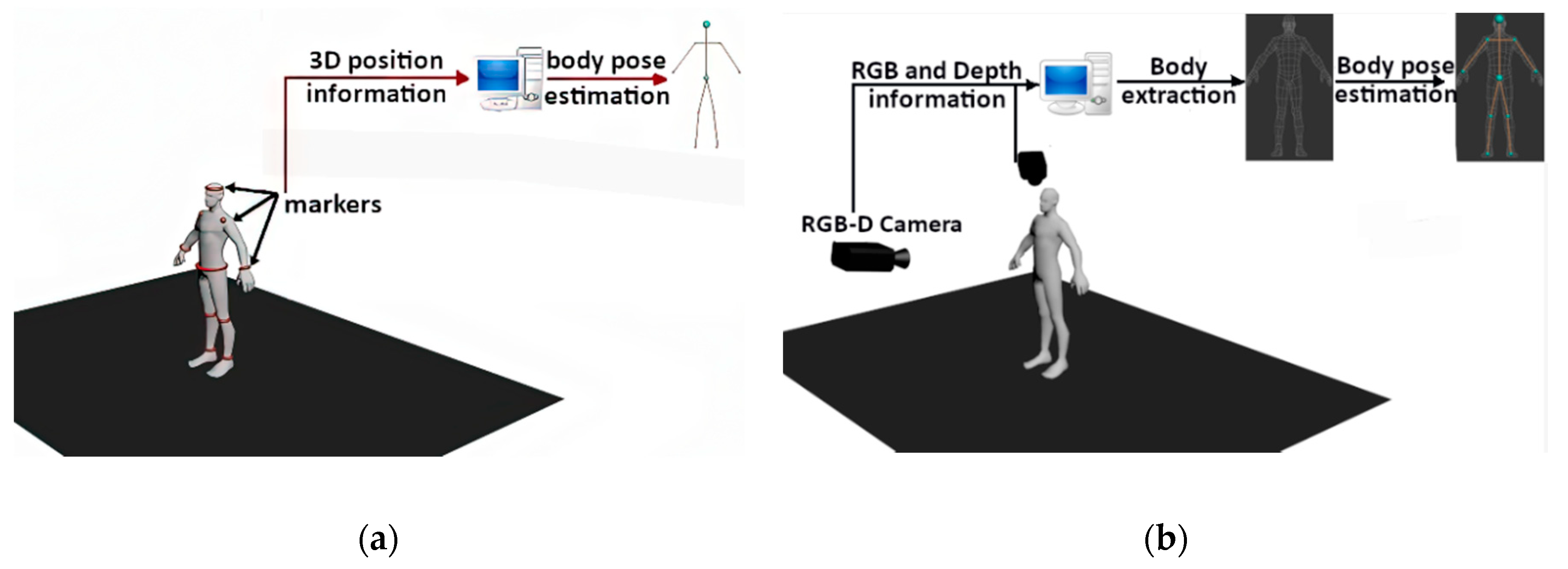
As mentioned earlier, correct detection, identification and tracking of a moving target in real time are a key part of the dynamic lighting system. Based on the information about its position, it is converted into a set of 3D coordinates that are necessary for the implementation of the audiovisual effects in the performance. The current object tracking solutions can be divided into two main groups (
Figure 1):
Marker systems—some special markers/sensors, which are placed or displayed on a moving object, are used to track the position in 3D space;
Markerless systems—object tracking is performed on the images from the cameras registering the scene. Here, we can list such techniques as based on 2D IR images and depth maps from RGB-D cameras or stereovision camera systems.
Marker-based tracking systems have their advantages and disadvantages. On the one hand, sensors provide precise and direct information on their position in 3D space and rotation at a high rate in real time. On the basis of this information, for example, a dynamic lighting of the moving target or the scene itself can be performed. On the other hand, however, markers in the form of mini devices or special clothing with the sewn-in sensors or transmitting components are placed on target objects or target object-shaped models, which makes it significantly difficult to maintain the high aesthetics of the entire system. Additionally, in many variants, these systems fail when the marker is covered, thus disrupting the tracking and identification of the object. In order to track the deformation of a non-rigid moving object, it is necessary to use a large number of markers or special materials, which causes a significant increase in the cost and complexity of the entire system. Marker methods are not suitable for tracking of multiple objects in crowded scenes. This is due to the necessity of installing a large number of markers and some problems with proper and unambiguous identification of many overlapping objects. It should be added that the so-called low “controlling intelligence” is a significant limitation of this type of systems as far as the lighting system is concerned. To enable the system to fit the width of the illuminated area to the object, control from a specialist operator is required. It is possible to adjust the light beam width and make it dependent on the distance of the dynamic luminaire from the object, knowing its position in the geometry of the scene; however, automatic adjustment of the beam to objects different in sizes—e.g., a child and an adult—cannot be performed in automatic and autonomous modes.
This is where the ideas of hybrid and completely markerless systems appear. The advantage of markerless systems lies in the reduction of the need for the use of special clothes or markers, allowing errors caused by covering up the sensor to be eliminated. Such systems can be used for a larger number of targets in the scene. It is essential for the algorithms to be capable of correctly classifying and identifying objects. As for human position and pose tracking, it is possible to determine their full geometry, skeletal points, or possible occlusions. Thus, we can correctly illuminate and map the entire surface of the body or its selected elements. A longer computation time is the main limitation on applying the markerless systems for the tracking of moving targets compared to the marker systems [
6,
7,
8,
9]. All markerless systems, which are based on an advanced signal and high-resolution image analysis from many cameras simultaneously, require utilisation of the so-called intelligent algorithms. It should be remembered that we track not only the objects that behave “flexibly”, e.g., a silhouette of the human body, but also the objects that can overlap and, from the point of view of a pl anar image on the matrix sensor, penetrate. To simplify the analysis, the rest of the article will focus on the analysis of a single object in the scene. Although the software of markerless systems seems to be crucial in terms of image analysis, some additional delays introduce the need for corrections to the recording devices. If the decision on the final position of the object in 3D scene is made on the basis of the analysis of images from the RGB-D cameras, it should be remembered that the parameters such as focal length of the lenses, dimensions of individual sensor pixels and the bit depth of analog to digital converter (ADC) converters have an impact on the geometry of the image and thus the position of specific points in the scene. This causes introducing the need for advanced optimisations that, by reducing the computation time, will not affect their accuracy adversely.
Most often, determining the position of the tracked object in 3D space is carried out on the basis of depth maps obtained from the RGB-D cameras or the stereoscopic camera system. The depth maps provide information about the distance of a point from the
Z camera. The remaining
X and
Y coordinates can typically be received by converting the
u and
v coordinates of each pixel with the use of the internal camera parameters (
uo,
vo,
αu, and
αv) and the information about depth value assigned to each pixel. Formula 1 describes the dependence of the transformation onto the perspective view of the pinhole camera that makes it possible to calculate the
X and
Y coordinates of the object:
where:
Xi, Yi, Zi are the global coordinates of the point in the space;
ui, vi are the pixel coordinates in the depth map;
uo, vo are the optical centre of the image;
αu, αv are the focal lengths.
2. Current State of Knowledge
An analysis of the literature shows individual scientific works on markerless tracking of moving targets. In the publications [
10,
11,
12,
13,
14,
15], vision systems are proposed for human position and pose tracking on the basis of depth maps obtained from one camera or numerous RGB-D cameras. These systems detect some characteristic skeletal points and determine the geometry of the body even in the event of the occurrence of occlusion. Most of the presented systems for the analysis and identification of the silhouette and the position of parts of the human body are based on the Kinect system directly. If the Kinect solution is not used, most often it represents a kind of reference. Unfortunately, this is a serious drawback of most studies, because it is impossible to eliminate any of the system limitations such as limited resolution or depth detection range, which is 4.5 m. This paper [
11] presents an analysis of precision and, for example, an impact of the use of graphics processing unit (GPU) in relation to the computation time. According to the authors, the application of GPU processors reduces the time necessary to analyse a single frame with the use of the central processing unit (CPU) alone from 0.5 to 0.05 s with the use of the NVidia GeForce GTX 480 graphics card capabilities. This makes it possible to achieve a stable processing time at the level of 15 frames per second. However, while using a single camera or a single Kinect system, the occlusions caused by an individual object itself are common. The analysis of paper [
12] shows that the systems based on the use of multiple RGB-D cameras for the purpose of detecting and identifying multiple human bodies offer good results. Most often, this means using more than one Kinect system that is supported by the implementation of genetic algorithms. The authors presented a system of three cameras placed along the circumference of a circle at an angular distance of 120°. This allowed them to eliminate any self-occlusions and correct identification of the position of three people simultaneously.
Markerless tracking of a moving object based on depth maps has also been used in research on dynamic, interactive video mapping. The paper [
6] presents mapping on an articulated movable doll. The mapping was carried out for the needs of a theatre play. The object tracking was performed on the basis of depth maps from the Kinect v2 device. In the next step, a virtual item of clothing on the object was modelled on the basis of the detected position, pose and surface geometry of the doll, and then the finished digital image was displayed on the real object. The delay caused by data download, processing and displaying was 6–7 ms.
The next example of a project implementing markerless object tracking can be found in [
7]. The authors of the study performed a dynamic multi-projection mapping on the face, operating in real time. Tracking and correct identification of the geometry and the facial expressions were based on depth maps obtained from the RGB-D Real Sense RS300 camera and a parametric model of the human face. The actor’s face tracking alone took 10.4 ms on average, while the total delay of the dynamic mapping process was about 20 ms. Two NEC NP-P451WG projectors with a resolution of 1280 × 800 pixels each were used in the project. For the achieved analysis times, a computer with an Intel Core i7 4771 (3.5 GHz) processor, with 32GB RAM and the NVidia GeForce GTX 1080 graphics accelerator was used.
In turn, [
16] presents a dynamic 3D reconstruction of the sand surface, mapping it with various colours in real time. Tracing, consisting of the reconstruction of the non-planar surface of the sand placed in a rectangular box, was performed without any markers on the basis of depth maps from the Kinect device. After mapping the unevenness of terrain, it was painted with a projection image, where the colour of individual parts of the object depended on the real value of the distance of individual surface fragments from the camera, thus on the height of the object built up. The authors obtained the object mapping frequency at about 30 fps.
The publication [
17] describes an intelligent lighting control system for a living room in real time. The operation of the system depends on a type of activity of the detected people, their position, motion direction and height estimation. Tracking of the people and the type of human activity was carried out on the basis of depth maps from a large number of RGB-D cameras. Several activity modes, such as learning mode, dialogue mode and TV watching mode, were implemented. Depending on the type of the performed activity and the people’s position in the room, the lighting conditions were adjusted to the needs. The proposed lighting control system was intended to demonstrate the opportunity to gain energy savings after applying this type of system to the rooms.
SLAM systems (simultaneous localisation and mapping) are applied in many areas, including automated vehicles, or augmented and virtual reality. Many systems of this type use RGB-D cameras to capture 2D and 3D data [
18,
19]. On this basis, the environment is reconstructed—both closed and open space—where a moving object moves, and, at the same time, the location and/or spatial orientation are estimated in real time. The current position of the camera/robot is calculated based on odometry and distance sensors. There are two main approaches towards creating land maps: a landmark map and an occupancy grid map. The first method of SLAM systems is based on the detection of landmarks with their coordinates in space and additional data enabling their identification. The second category of SLAM systems divides the space around the robot into the fields of a fixed size and assigns them an occupancy value. On the basis of this information, the presence of an obstacle in the immediate vicinity is determined, and its size is also estimated.
RoomAlive [
20] is a system that performs an interactive dynamic video mapping in any large room. The system consists of six sets of projector–camera devices. Three-dimensional room reconstruction and human body position tracking are based on depth maps and RGB photos. The image displayed from the projectors is adapted to the room furnishing, whereas the user can interact with the displayed content in real time. An ordinary room is transformed into space for augmented reality.
Markerless systems are under continuous development; however, currently, there are no fully reliable dynamic systems of high accuracy for identifying the position of an object, based on RGB-D cameras, capable of handling a large scene whose dimensions are close to 20 × 10 m. This is why nowadays, commercial projects that operate based on a marker system for tracking of moving objects in real time are implemented very commonly. BlacTrax [
21,
22] is a popular and widely used system for tracking the position of objects in 3D space in the entertainment industry around the world. It is the marker system in which every tracked object is equipped with miniature infrared markers. With this solution, it possible to detect the position with the use of 3 or 6 degrees of freedom (x, y, z coordinates and angles of rotation around these axes), and then to use this information to control various devices: surround sound, automatic lighting, media servers, video projections and automatic cameras. The whole system operates in real time, and the delay is at the level of 3 ms [
22].
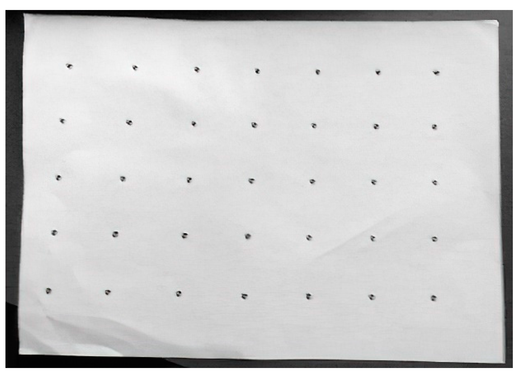
A marker system for mapping moving non-rigid objects, such as a T-shirt or flexible piece of paper, is presented in [
8,
9]. In [
8,
9], tracking a moving surface is based on observing a special pattern in the form of a board, printed with IR ink on the target object, i.e., sheet of paper and T-shirt, with an IR camera. An example of this type of marker is shown in
Figure 2. The use of this type of ink means that the print is invisible to the human eye. The efficiency of tracking markers in both publications is 0.2 and 1 ms, respectively. The disadvantage of these systems, however, is that the tracking and mapping areas are limited to the area that is covered by the marker.
A marker in the form of a special material embedded in the object is used in [
23]. A projector–camera system is presented for mapping non-planar surfaces in real time. The deformation of the object surface is traced with the use of marker. Later, this mapping of the surface is applied to a digital image that is projected onto the real deformed object. Materials for the production of this type of markers are characterised by a high price, which is a significant limitation on their application.
The marker tracking system for a moving person was used in [
24,
25]. In both cited publications, the authors applied the markers placed on the chest, arms, and legs to identify the type of activity performed by the observed person. In [
26], a marker determination of articular angles for the ankle was proposed. The reflective markers were placed on the knee, ankle, and foot. The authors applied the Kinect device, where the detection and tracking of markers were conducted with the help of an IR camera, and the depth maps were used to determine their coordinates in 3D space. The papers [
27,
28] present the joint use of depth maps and markers placed on a moving person. Based on the information from the markers, the actor’s skeleton was estimated and tracked. The aim of applying the markers was to increase the correctness of detection of articular angles, and thus the correctness of the actor’s pose estimation. The data from the depth maps were used to receive the information about the geometry of his body. Both systems also showed high precision of operation in the event of their own occlusions.
Currently, full identification of a human silhouette and person’s position based on the authors’ system of image analysis from many high-resolution RGB-D cameras with the hybrid operation option seems to be the most accurate method. As far as the hybrid operation is concerned, the system will be capable of using the markers for continuous recalibration and data control obtained from the transformations of information provided by the RGB-D cameras. Towards this aim, the developed system will operate avoiding the Kinect-type systems that will be used only at the first research stage in order to learn about their capabilities and limitations. Most scientific works related to this topic are based on the Kinect system, but no article presents any research that thoroughly verifies this tool. This is the reason why it is impossible to unequivocally state whether the hardware and the Kinect library specification or the processing time of algorithms developed by the authors of individual publications are mainly responsible for the resultant analysis time.
3. System Description
As far as the topic discussed is concerned, the target system is an expanded system that is based on many RGB-D cameras, used to acquire data about the scene and the objects within it. To obtain a dynamic mapping of high precision, full knowledge of the features, position, and construction of objects in the scene is required. The projector system, used for “painting with light”, which means implementing the dynamic lighting and mapping the objects with graphic and multimedia content, will be the second key part of the system. The time of data acquisition and processing is an essential point of reference in the created dynamic lighting systems. This time is responsible for a level of the delay generated between the current position of the object and the image displayed from the projector on it. Therefore, the total time of this process translates into an admissible motion rate that cannot be exceeded for the moving target in order to provide a precise adjustment of the image to the object. For example, an object moving at a low speed of 5 km/h does 1.389 m in one second. With such a rate for the moving object, for 30 frames per second, the subsequent images will change for the object moved by 4.6 cm. Such precision is acceptable for the purpose of illuminating or mapping the entire human silhouette, but in the case of a hand moving at this rate, the individual fingers will not be illuminated during the movement. If the delays related to image processing and displaying are taken into account, during such a mapping procedure, an “intelligent” factor, which will measure the speed and predict the position of objects, should be introduced into the system. Otherwise, already at a speed of 5 km/h for the objects such as hands, the images may illuminate the spaces between the fingers, instead of the fingers themselves.
For this reason, at the first phase, it is crucial to analyse the images in terms of data processing speed and to determine what the “bottleneck” in the entire dynamic video mapping process is. For this purpose, video projections were performed on two objects of similar characteristics, in which the impact of resolution of the image displayed from the projector on a level of the generated delays was investigated. The following mapping processes were carried out on the following:
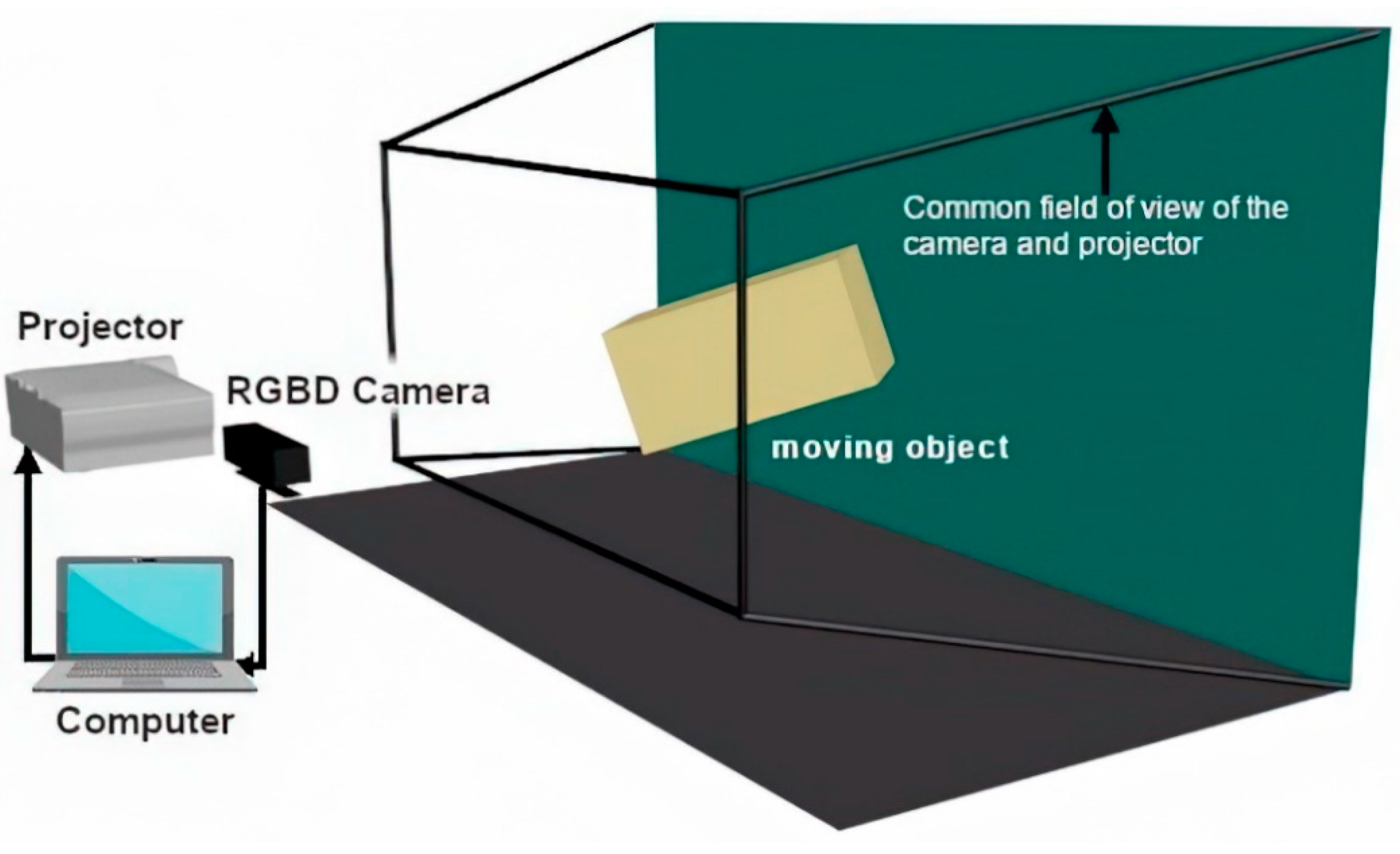
The system for dynamic mapping of moving objects consists of an RGB-D camera that captures the depth maps and a projector to display the image on the moving target object. To ensure the correct video projection, this moving object has to move within the common field of view of both devices.
Figure 3 shows how to place the camera and projector. The test software for dynamic video mapping has been created using the Labview [
29] environment and the modules for Machine Vision [
30] that provide the quick recording and processing of images from any camera.
3.1. RGB-D System Calibration
The system calibration is a basic system part on which the precision of reading of the object position and the accuracy of lighting system depend. It consists of bringing the devices and objects in the scene to one coordinate system. In other words, the camera–projector calibration means transforming the camera view (2D + depth) through 3D space into the 2D projector view corresponding to it. Therefore, each point (
Xc, Yc, and
Zc) from the RGB-D camera space can be adjusted to the corresponding points (
Xp, Yp, and
Zp) in the projector space in accordance with dependence (2):
where
R is the rotation matrix of 3 × 3 dimensions and T is the displacement vector of 3 × 1 dimensions.
Additionally, the transformation of the point from the projector space to the projector screen space is described by Formula (3), whereas Formula (4) shows the correlation between the camera space and the depth image recorded by this camera.
where
and
are the coordinates of the point in the projector screen space, and
, ,, and
are the internal parameters of the projector,
where
, and
are the coordinates of the point in the RGB-D camera screen space, and
, ,, and
are the internal parameters of the camera.
After consolidating the dependencies described in Formulas (2)–(4), the coordinates of the point in the projector screen space
, and
) depend on the coordinates of the corresponding point
and
) in the depth image and the value of the information about depth
Zc included in it. This dependence is as follows:
where
q1,… q11 are the constant coefficients.
Therefore, each pixel (
xci and
yci) of the depth image from the camera can be transformed into the corresponding points (
xpi and
ypi) in the projector image by means of the following transformation:
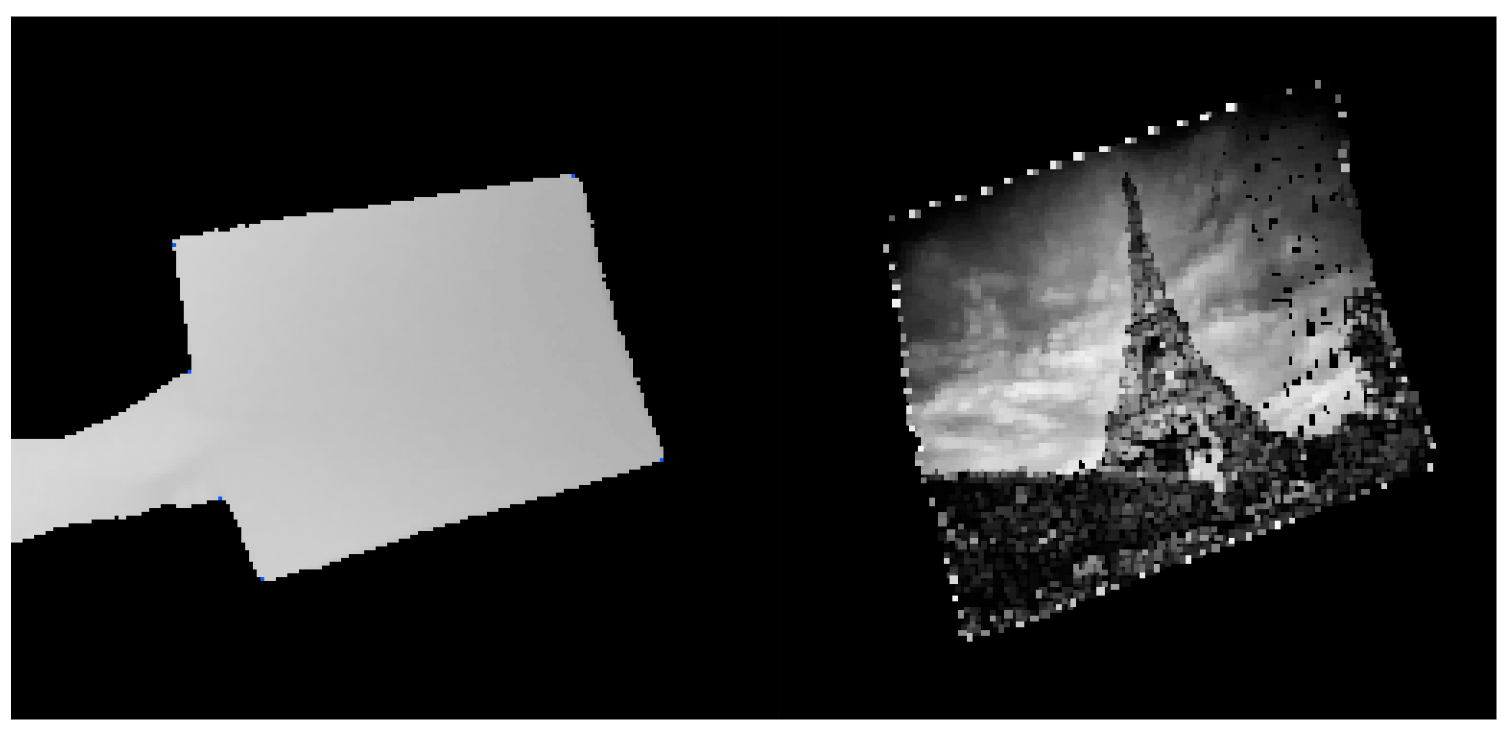
In order to carry out the dynamic mapping of the moving object, the novel 3D-to-2D function was performed, which, put simply, transforms the image obtained from the RGB-D camera into the image corresponding to it, displayed from the projector in accordance with Formula (6). From this transformation, we receive the image adjusted to the projector view and resolution, and the displayed image “fits” to the moving object in the scene, taking into account its geometry (
Figure 4) or information on the depth of its characteristic points.
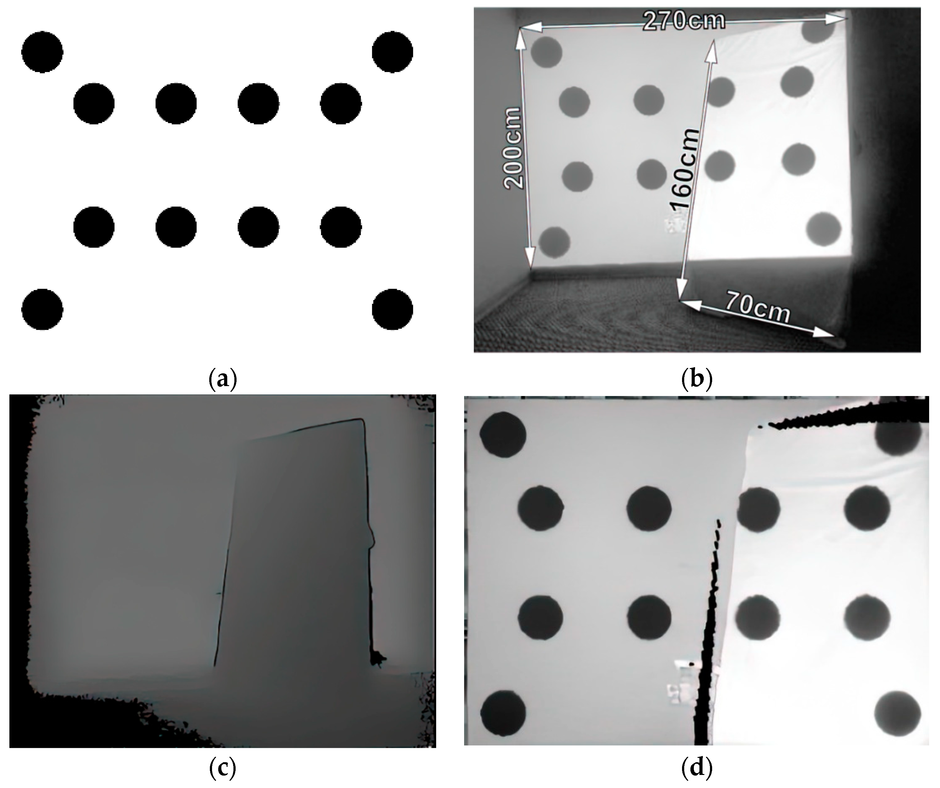
The aim of the calibration process is to estimate the transformation matrix with dimensions of 3 × 4, which conditions the correct operation of the 3D-to-2D function. The calibration is performed on the basis of five pairs of RGB-depth photos for different settings of the projection surface. In the first step, the projector displays an image containing a pattern of the known coordinates of centres of the circles. Next, the RGB image with a resolution of 480 × 270 px and a depth map with a resolution of 512 × 424 px are recorded. In the RGB image, the circle detection is carried out, and the coordinates
xi, and
yi of each detected centre are converted to the corresponding coordinates
xci and
yci in the depth map where the information about depth
Zci is then read out. The 3D-to-2D transformation matrix is calculated on the basis of five sets of the coordinates of centres of circles and the information about their depth as well as the coordinates corresponding to them in the projector image.
Figure 5 shows an example of the image displayed from the projector, a pair of RGB-depth photos and the image gained as a result of the 3D-to-2D transformation.
3.2. Perspective Transformation
Applying a perspective transformation, it is possible to fit the image to any quadrangular shape. The principle of operation of this type of transformation is described by Dependence (7), where
i and
j are the coordinates of the image corners after transformation, and
i’ and
j’ are the coordinates of the image corners before the transformation. The coefficients
p00, …, p22 are the values of the perspective transformation matrix. Eight of these parameters can be calculated with the use of four pairs of the corresponding points in two images—the input image and the output image.
The perspective transformation was used to digitally apply the raster or vector images to the surfaces of moving objects such as a sheet of paper or a cuboidal object. In order to map this type of surface in real time, the perspective transformation matrix is computed in each iteration on the basis of four pairs of the corresponding points—the coordinates of the boundary corners of the image (to be displayed on the object) and four points detected in the depth maps, considered as corners located within the plane containing the mapped surface. The method for determining the parameters of the perspective transformation matrix is described by dependence (8).
After calculating the transformation matrix (Formula (8)), the perspective transformation is applied to the image. This means that each pixel of the input image (
xoi and
yoi) is converted into the corresponding pixel coordinates (
xi and
yi) in the output image in accordance with Dependence (9):
As a result of this operation, the image is geometrically fitted to a specific surface of the object. The principle of operation for such a transformation is shown in
Figure 6, with
Figure 6a displaying the digital image for mapping in the first place,
Figure 6b the image with the marked points corresponding to the corners of the sheet, and
Figure 6c the result of the perspective transformation.
3.3. Dynamic Video Mapping of Moving Surfaces
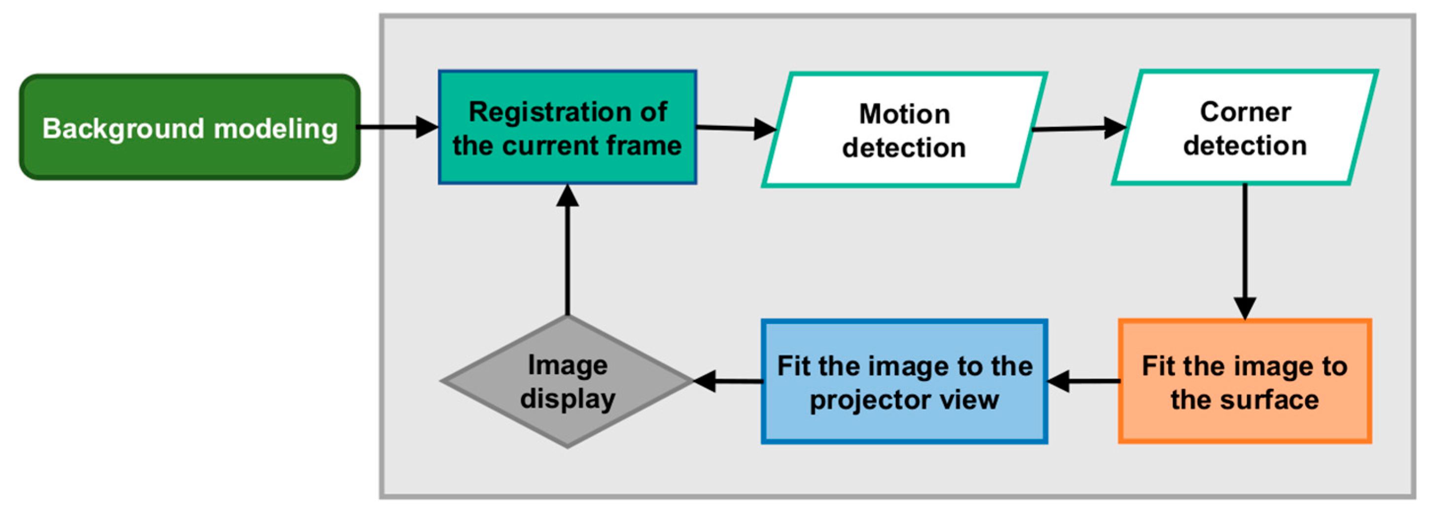
In order to verify the algorithms and determine the potential of the developed system, the focus was placed on planar surfaces. The surface of the paper sheet was the first, followed by the faces of a cuboidal box. The process diagram is shown in
Figure 7. The real-time object mapping process consists of the following:
Tracking the target rectangular surface where the image is displayed—motion detection of the object located in the common field of the camera and projector’s view, and identification and tracking of the corners of rectangular surfaces;
Fitting the image to the surface or the specific faces of the cuboidal object—performing the perspective transformation for each mapped surface;
Transforming the final image to the projector view—using the 3D-to-2D transformation;
Displaying the image from the projector.
Motion and corner detection of the rectangular surfaces of the moving object will be discussed further in this publication.
3.4. Moving Object Detection
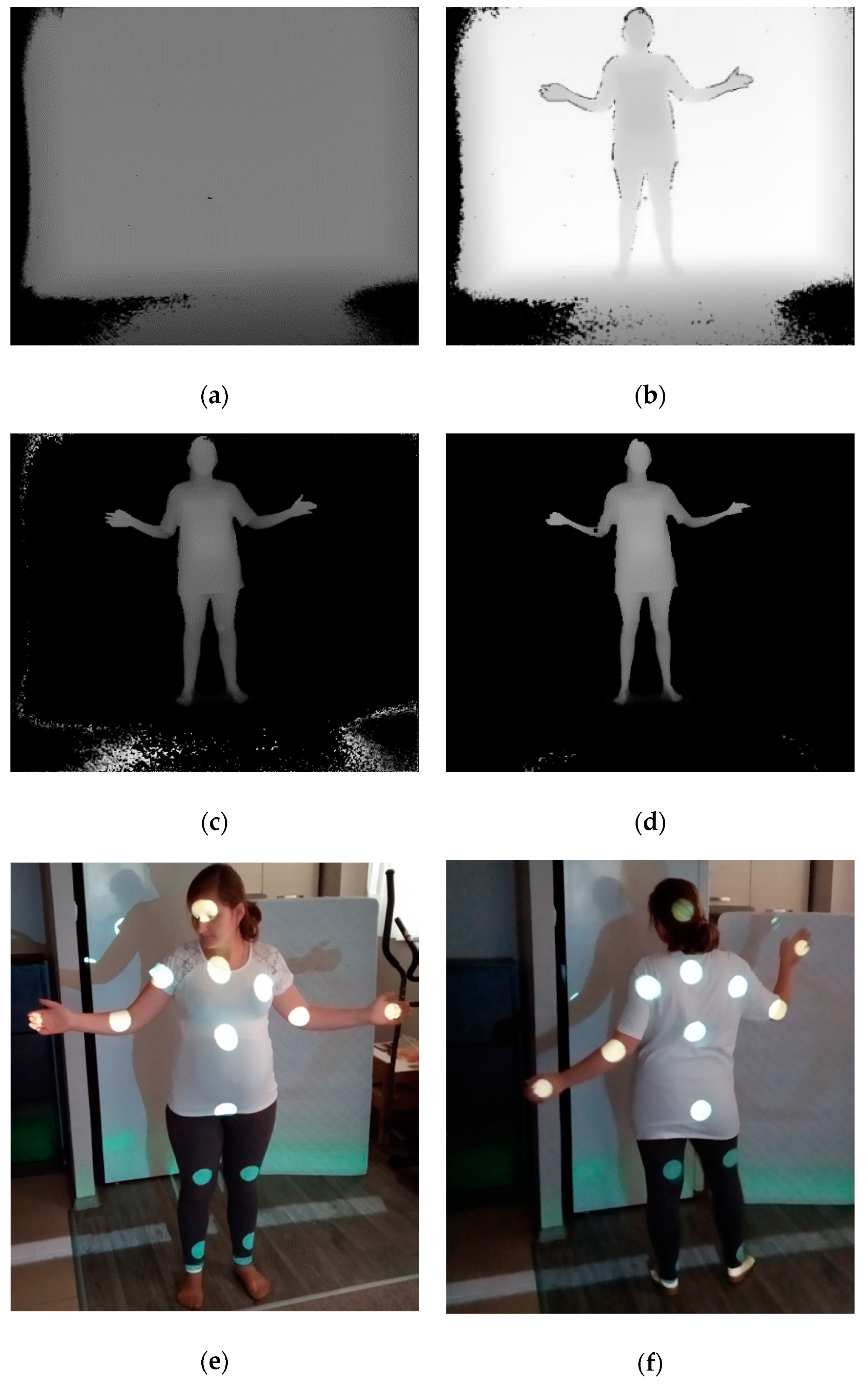
In the next step, the problem of detecting the moving object was solved on the basis of the background extraction method (
Figure 8). With this method, it is possible to determine which image pixels belong to the moving foreground objects. First, the background modelling takes place. It should be remembered that this is not a graphic background, but a background with the depth maps fully taken into account. Background modelling is carried out by registering 10 consecutive correct photos of the depth maps and determining the arithmetic mean of them, excluding the extreme values. At this stage, it is important that the moving object should not be in the field of camera view. Then, the frame is captured with the current depth map where the moving object is already visible. It should be noted that regarding the RGB-D camera used, the quality of the received depth maps (we refer to a high quality of the obtained depth maps in the case of a value of zero or a very small number of points with zero values for which the depth has not been determined) increases together with a fall in luminance occurring within the registered scene. At the next step of motion detection, the background extraction from the current frame is performed. The difference of images shows not only the moving object in the scene, but also the single non-zero pixels, which are referred to as noise (
Figure 8c). Two problems are a source of this noise: First, in the process of generating the depth maps, the pixels with zero values are created at the edges of objects (
Figure 8b). This type of noise is characterised by high values equal to the depth in the background image. Thus, the best solution is to perform a mapping process on a planar surface, e.g., a wall, because, then, the pixels corresponding to this noise can be eliminated by applying a threshold whose value is equal to the distance between the wall and the camera. Moreover, the pixels whose values are higher than the threshold are zeroed. The second source of noise is the difference in values of the corresponding pixels in the images—the background and the current frame—arising from, among others, the lighting conditions while recording these depth maps. The pixel value corresponding to this noise oscillates in the range of 0.5%, and its elimination also consists of applying a threshold below which all pixels are zeroed. The single pixels that do not fall in both thresholds are removed using some morphological operations such as Erode, POpen and PClose. The final result of motion detection is an image in which only non-zero pixels represent the moving object in the scene (
Figure 8d).
The use of the background extraction method in the process of dynamic mapping of moving objects means that the developed system can also be applied to dynamic mapping or floodlighting of more complex objects, e.g., a moving silhouette. The correct identification of the characteristic points, i.e., joints, is then required.
Figure 8e,f show the human silhouette with the elements of physiognomy marked by projecting the image with spots of light at the points corresponding to the coordinates of the joints. This procedure makes it possible to verify the precision of the analysis and the accuracy of the identification of a moving object in the scene.
3.5. Corner Detection for Rectangular Surfaces
To carry out the surface corner detection, the corner detection function, whose operation is based on the Harris [
31] or Shi–Tomasi [
32] corner detection algorithm, was used. The Harris corner detector computes a response function R for each pixel in the image. If it is a local maximum and it is higher than the threshold value, this point is then considered as a corner. The response function R is computed by the autocorrelation matrix
M(p) in accordance with the following dependences (Formulas (10) and (11)).
where:
Ix(p) is the horizontal image gradient at position p;
Iy(p) is the vertical image gradient at position p;
ω(p) is the Gauss filter function;
k is the coefficient whose value is in the range of 0.04–0.06.
The Shi–Tomasi corner detector is based on the Harris detector, but there is a difference in the corner selection criterion.
The characteristic points are detected as a result of applying the corner detection function to the image. First, one has to define the corner detection options, i.e., select the detection method, specify the minimum force to qualify the point as a corner, and determine the Gausian kernel size. This function examines each image pixel by analysing the surroundings and specifies whether there is a corner in a given place. The function returns the
x and
y coordinates of all detected corners. In the next step, it is necessary to determine which of the detected points correspond to four corners of the surface to which the image should be fitted. For this purpose, the 2D coordinates of all detected points in the depth map are converted into three-dimensional coordinates. In the further step, the lengths of the segments between individual points are determined, and the parallelism of the created segments is tested. The points that belong to the parallel segments and the length of these segments that is close to the length of the faces of the tracked surface with a tolerance of ±10% are considered as the corners of the surface. An additional criterion is used to eliminate possible errors. This condition checks whether the faces of the detected surface are perpendicular. It should be added that the transition to 3D space is necessary because two straight lines that are parallel or perpendicular in 3D space are usually oblique in a 2D image. This arises from the perspective view that occurs with the pinhole camera. The result of the corner detection function and the algorithm determining four corners of the rectangular surface is shown in
Figure 6b, in which the detected points considered as corners are marked with the arrows, and the remaining points are rejected.
3.6. Creating Maps Projected onto the Surface of an Object
In the case of projecting a digital image on the surface of a moving sheet of paper, the projection mapping, where the paper sheet is mapped with a greyscale image, was performed. For the cuboidal box, the transformations which make it possible to use 24-bit colour images, were used. The application of the transformations for monochrome and colour images was to show the difference in duration and computational complexity of the developed transformations. Additionally, for the piece of paper and the box, two mapping options differing in the sequence of performing the transformations—perspective and 3D to 2D—were investigated. Those options were as follows:
Variant I—First, the perspective transformation was performed, where the resultant image was the image with depth map resolution (512 × 424 px); then, the 3D-to-2D transformation of the image was used to fit the resolution and the projector view.
Variant II—At the first stage, the individual points considered as surface corners were transformed into the projector system, and then the image was adjusted to the new coordinates by means of the perspective transformation.
In the first solution, both transformations were applied to the entire image, but the change to resolution was made after applying the 3D-to-2D transformation. In the second option, only the perspective transformation was carried out on the whole image, and it was responsible for changing the image resolution to the dimensions of the projector. The 3D-to-2D function was only used for single pix.
4. Processing Time Analysis Results for Entire Process
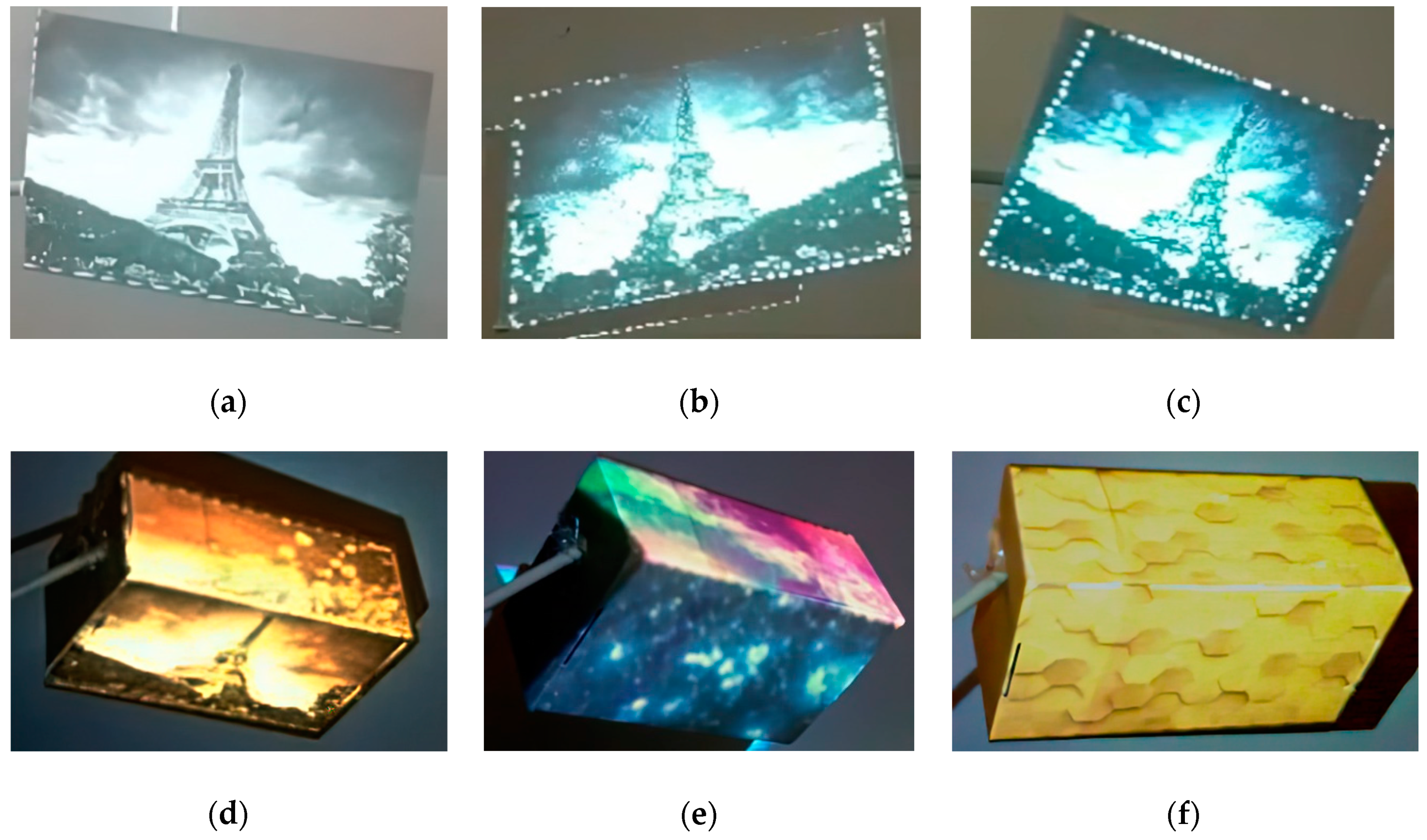
The dynamic video projections were performed on two different objects: an A4 paper sheet (
Figure 9a–c) and a box (
Figure 9d–f). Additionally, for each of the objects, two variants different in the way and sequence of using the image transformations were carried out. The duration measurements of sub-processes, such as motion detection, corner detection, perspective transformation, 3D-to-2D transformation and image display time, were taken. In addition, the length of time for the depth map download in the box mapping process was measured.
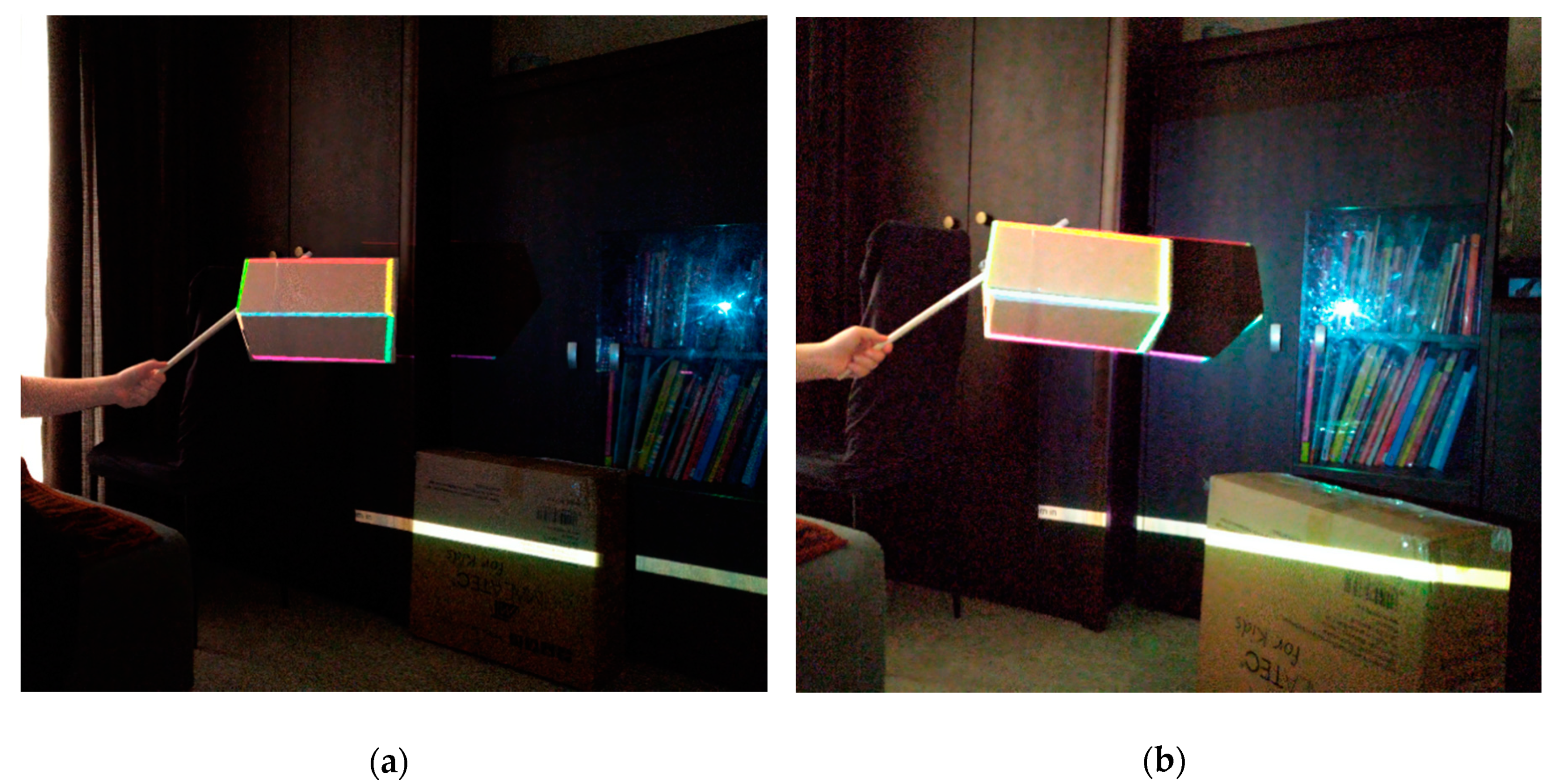
In order to verify the process, some attempts at mapping the object located in the room with other objects that could potentially impact the precision of the algorithms determining the location of the object in space were made.
Figure 10 shows the mapping on a box which consists of “painting” its edges. The obtained results clearly present that the system based on the analysis of depth maps makes it possible to also obtain the precise spatial identification of objects in such conditions.
4.1. Planar Objects
The object motion detection and limited surface corner detection are always performed with the use of depth maps with a resolution of 512 × 424 pixels, giving the result of 217,000 points falling onto a single image. A computer with an Intel Core i7 9750H (2.6 GHz) processor with 16 GB RAMs and graphics accelerator NVIDIA GeForce GTX 1660 Ti was used for the analyses. The motion detection time was 1.457 ms, including 1.027 ms for the detection time of the corners of the mapped surface. The perspective and 3D-to-2D transformation times, as well as the display time for four different projection image resolutions, are shown in
Table 1. Based on the received results, it can be seen that the transformation times increase together with a growth in output image resolution. When the 3D-to-2D function is used just for four points (and only later the perspective transformation is applied) that correspond to the successive corners of the plane, the time of this transformation takes just 0.0765 ms.
4.2. Cuboidal Objects
Table 2 and
Table 3 show the times of particular parts of the process for dynamic mapping of the moving cuboid. Analogically to the moving paper sheet mapping, the depth map download, the motion detection, and the corner detection are always applied to a constant resolution. The average duration of this process was as follows: 1.0596 (depth map download time), 1.175 (motion detection time) and 1.149 ms (corner detection time), respectively. The image resolution did not have a significant impact on the time of sending the image to the projector, and its value was 0.0103 ms on average. It should be noted that the transformation times for colour images are higher than those obtained with the greyscale image mapping process. The results presented in
Table 2 and
Table 3 show that the perspective transformation and 3D-to-2D transformation times significantly increase together with a growth in projector resolution. As for the FullHD resolution, the duration of these image transformations is several times higher compared to the low resolution of 640 × 480 pixels. In the case of perspective transformation, the transformation times increase proportionally to the number of pixels that form the image. For example, the ratio of the times obtained for the resolution of 1280 × 800 pixels to the resolution of 640 × 480 pixels is 2.96, and the ratio of the number of pixels of these images is 3.33. However, the achieved operation times of the 3D-to-2D function do not show any proportionality to the dimensions or number of image pixels.
The perspective transformation times for colour images increase from 4.11 to 24.52 ms, and for the 3D-to-2D transformation, from 5.43 to 22.77 ms. As mentioned earlier, a separate perspective transformation is required for each mapped rectangular surface. Therefore, in the case of mapping two faces of the box, the received times have to be doubled to obtain the total time for fitting the images to the target surfaces. Currently, the test software uses a single core of the processor to illuminate or map a person. With the Labview environment, it is possible to create multithread software products and to use many algorithms simultaneously. Each of the threads can operate independently or be synchronised with others. Thus, it is possible to send each of the transformations to the separate threads in order to minimise the mapping process time, thereby increasing the efficiency of use of the entire processor. The second way to reduce the delay is to use the 3D-to-2D transformation only for individual corners of the surface, because the duration of such calculations was insignificant, and it was 0.0697 ms. The disadvantage of this solution, however, is the fact that the use of the 3D-to-2D function for the entire image makes it possible to fit the image to any possible convexities or irregularities on the mapped surface.
4.3. Comparison of Results and Discussion
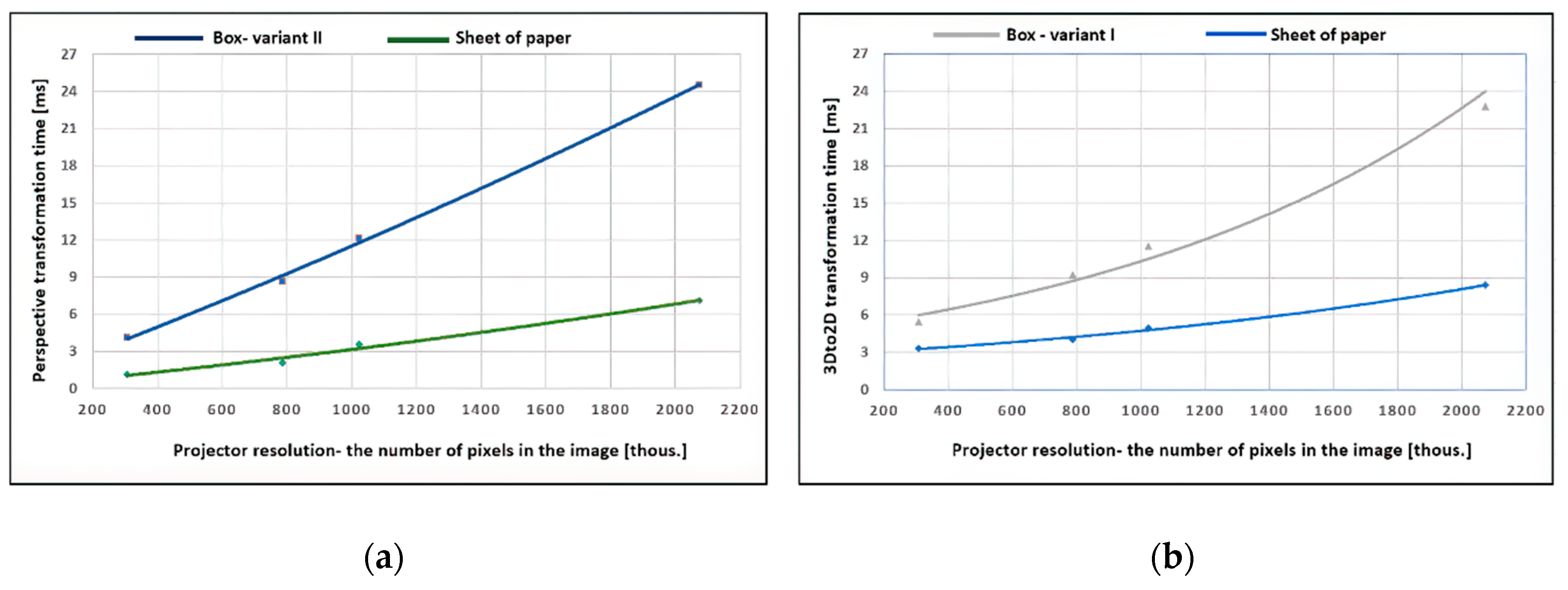
The perspective and 3D-to-2D transformation time results received in the processes of dynamic mapping of the sheet of paper and the box are collected and compared in
Figure 11.
Figure 11a shows the dependence of the perspective transformation time of the image as a function of the target image resolution (the number of pixels composing the image), i.e., displayed from the projector. The results of the greyscale image transformation times (green marks) and the colour image transformation times (blue marks) were approximated in the form of a polynomial function of the second degree.
Figure 11b presents the visualisation of times for the 3D-to-2D function, received in the mapping process: the A4 paper sheet (blue colour) and box—variant I (grey). All obtained data were approximated by an exponential function.
The gained image transformation times show that their increase is compliant with the characteristics of the quadratic and exponential functions. Thus, the resolution of the final image has a significant impact on the total delay generated in the process of projecting the image on the moving object in real time.
The RGB-D camera used makes it possible to register the depth maps with a frequency of 30 kl/s, which translates into a distance of 33 ms between consecutive frames. By adding the delay resulting from data download and its processing, the frequency of the moving object mapping decreases. As for the projection with a greyscale image and resolution of 640 × 480 pixels, the delay for the optimal variant is about 5 ms (1 ms—depth map download, 1 ms—motion detection, 1 ms—corner detection, and 1–2 ms—image transformation), which translates into mapping frequency values of 26 kl/s. On the other hand, for the FullHD resolution, the highest frequency that was obtained was 23 kl/s, because the delay increased to about 10 ms.
When analysing the times obtained for the transformation of colour images, it can be seen that they are much higher than the transformation times of greyscale images. This obviously translates into a lower frequency of moving object mapping. For example, as far as the lowest tested resolution of the output image is concerned, in the case of mapping of only one face, the delay is about 8 ms, which translates into a frequency of 24 kl/s. If we map two faces, the delay increases to 12 ms, which gives 22 kl/s. For the resolution of 1920 × 1080 pixels, when projecting on one or two faces of the box, the delay is much higher at 28 and 52 ms, respectively. As a result, frequencies of 16 and 12 kl/s are achieved.
The developed system that accomplishes identification and mapping of moving targets is based on the original 3D-to-2D transformation (Equation (6)), which allows for matching the displayed images to the geometry of the object based on its position in space (
Figure 8,
Figure 9 and
Figure 10). Additionally, during the development works, known algorithms of a perspective transformation of images [
33] were used to adjust the graphic content to the flat elements of objects. The aim and priority of the presented phase of the research was to analyse the data processing times in the process of dynamic lighting/mapping of moving objects and to show which transformations generate the greatest delay. This approach allows one to examine the throughput of the analysed data in order to obtain the target mapping frequency of a moving object.
The total time of data analysis and processing translates into the level of delay between the displayed image and the current position of the moving object. Therefore, this time (and correct identification) also has an impact on the precision of fitting the graphic content to the object. First, transformation time optimisation is essential to make it possible to obtain the frequency of mapping of a moving target at the assumed level dependent on the size of the object alone. During the next stage of the research, we aim to measure (1) the precision of adjusting the projection image to the object that is important for system quality evaluation and directly dependent on the presented speed of movement of the object and (2) the precision of predicting the movement direction implemented in the target algorithm.
5. Conclusions
Motion tracking and human body identification based on an advanced image analysis and data from RGB-D cameras represent a very future-oriented field. Marker systems commonly used for these purposes have numerous limitations. It is possible to use them to implement semi-autonomous image and sound control, e.g., on the theatre stage or in television studios, but it is generally very difficult or almost impossible to go beyond the identification of the object position alone and the motion direction. In order to identify, for example, individual parts of the human body, a very large number of markers should be used, which at least will correspond to the number of the main human bones. It is obvious that these types of systems cannot be used in dynamic projection mapping systems, but it is also extremely difficult to adapt them to systems supporting intelligent glare reduction to illuminated objects or observers. Similar systems perform well while directing the light from dynamic moving heads in hybrid systems, where the presence of a light operator is always important. This paper generally focuses on the processes and algorithms required for the development and implementation of autonomous markerless object tracking and human body identification systems for the needs of dynamic projection mapping and intelligent floodlighting of objects and surroundings. Floodlighting of intelligent objects and the environment is understood as illumination implemented with projector systems of high brightness and high resolution, which, based on data from RGB-D cameras subjected to a computer analysis, will make implementation of a lighting system with glare reduction in relation to illuminated objects and observers possible. With the current rapid development of high-luminance light sources (e.g., LED) that reach the levels of 10
8 cd/m
2 [
34,
35], discomfort glare connected with the occurrence of high luminance values in the field of view is a particularly important problem that must be solved quickly. While performing a full identification of individual parts of the human body, it is possible to implement a complete lighting system with the use of multimedia projectors that will be capable of reducing the luminance of crucial zones, e.g., the actor’s eyes, imperceptibly for observers. The aim is to significantly reduce discomfort glare or its complete elimination. Of course, we cannot narrow down the fields of similar system implementations only to theatres, concerts, or conferences. Having a full identification of the human body and the direction where they are looking and moving, it is possible to adjust the displayed multimedia content that is in their environment. The basic assumption of the target system is to provide the maximum possible versatility and great intelligence of data analysis from RGB, IR, RGB-D cameras, avoiding the Kinect-type systems, which by definition have their own specifics that can limit the project possibilities. This will help in implementing the system in projection mapping applications with a dynamic darkening of crucial zones, e.g., people leaving the object, adaptive projection mapping, augmented reality system implementation, dynamic people, and object floodlighting. The implementation of adaptive driving beams with darkening of sensitive zones as for vehicles and potentially people moving along the side of the road is a possible version of the developed system implementation.
Information gathered about the position of the moving body—space, direction and type of activity performed—allows the proposed system to be adapted for use in office and residential premises. The identification of the location and movement of figures along with utilisation of lighting in a given room allows one to adjust the lighting conditions to the current needs by dimming or completely switching off selected luminaires. Furthermore, the use of projectors in the lighting system enables the improvement of working conditions and visual comfort for employees, e.g., by dimming zones that may be inconvenient or cause a feeling of discomfort. Additionally, the system allows one to dim areas where lighting is unnecessary. For example, with regard to office rooms, which are mostly open space, it is possible to darken unused areas, illuminating only those parts of the room where employees are located. The potential application of the system is so broad that it can be directly implemented, for example, in museum spaces or art galleries, by changing the luminance of illuminated zones to align with the viewer’s gaze.
The current phase of research includes the implementation of dynamic image analysis and processing systems in order to correctly identify and position a human body in the 3D scene. Some work that leads to achieving this goal is presented in this publication. The key time analysis has shown (
Table 1,
Table 2 and
Table 3) that the sequence of transformations and the resolution of the analysed image are of key importance to optimising the algorithm questions to make it possible to obtain the assumed number of frames per second, guaranteeing a smooth effect fitted to the illuminated or mapped object. At the same time, some care should be taken of the opportunity to fully use all threads of the main processor and graphics because large numbers of data points and high complexity of computational processes have to be associated with a calculation time that is as short as possible. A complete cycle of image registration, calculations and content display must be shorter than the inverse of the assumed framerate.
Hybrid technology based on the use of recording devices, operating both in infrared (IR) and visible light (B/W, RGB) with depth detection (RGB-D) support, will be capable of correctly identifying objects in real time, located in a specific part of the field of view (scenes). As a result of this, it will be possible to develop intelligent systems for mapping objects with graphic images, intelligent sound and lighting systems using movable heads and multimedia projectors, including systems simulating virtual object floodlighting, by artificially brightening parts of the scene and generating artificial shadows.


