Abstract
In the study, an interrupting performance test on the 145 kV gas circuit breaker is performed according to three different gases: SF, g (5% Novec4710 with 95% CO), and CO(70%)/O(30%) gases. Thanks to research advancements, it is confirmed that CO and g (5% Novec 4710) gases, respectively, have 40% and 75% dielectric strength, compared to that of SF gas. The filling pressure and transient recovery voltage criteria of each gas were determined differently in order to compare the maximum interrupting performance of each gas. The pressure of SF gas was determined to be 5.5 bar, which is typically used in circuit breakers. The pressure of the other two gases was determined to be 8.0 bar (the maximum available pressure of the test circuit breaker) to find the maximum interrupting performance. Moreover, the rate-of-rise of transient recovery voltage of SF was determined as 10 kV/s, which is the value at the state of maximum interrupting performance of the test circuit breaker with SF. On the other hand, the rate-of-rise of transient recovery voltages of g (5% Novec4710 with 95% CO) and CO(70%)/O(30%) gases were, respectively, determined as 4∼5 kV/s to find the interruption available point. The characteristics of arc conductance, arc current, and arc voltage near the current zero, and post-arc current are analyzed to compare the interrupting performance, according to different arc-quenching gases. The arc current is measured using a current transformer (Rogowski coil), and a signal processing method of the arc current and arc voltage is introduced to increase the reliability of the interrupting performance results. As a result of the test, it is confirmed that the critical arc conductance for all test conditions converged within a certain range and the value is around 0.7 mS. In addition, the critical current slope just before the current zero-crossing during the interrupting process is shown to be 1.8 A/s between interruption success and failure. Consequently, it is verified that the CO(70%)/O(30%) mixture and g (5% Novec4710 with 95% CO) have a similar arc extinguishing performance and SF has a relatively higher extinguishing performance than that of CO(70%)/O(30%) mixture and g (5% Novec4710 with 95% CO) under the aforementioned filling pressure and TRV conditions.
1. Introduction
SF gas has been widely used for high-voltage equipment, such as gas circuit breaker (GCB) and gas-insulated switchgear (GIS), because of its excellent insulation and arc-quenching capability [1,2]. SF is also stable, non-toxic, and has no ozone depletion potential (ODP). However, SF has extremely high global warming potential (GWP), which is about 23,500 times higher than carbon dioxide (CO) with the same mass, according to 2013 report of Intergovernmental Panel on Climate Change (IPCC) [3,4,5]. For this reason, the interest in alternative to SF gas has increased as a part of GWP mitigation in the high-voltage circuit breaker area.
The types of gases considered as alternative gases are natural gases, which are refer to the composition of atmosphere, SF gas mixtures with natural gases, SF gas mixtures with fluorocarbons, fluorinated gases except for SF (perfluorocarbons (PFCs)) and other new gases [5,6,7,8,9]. Table 1 shows the properties of several gases where E is the critical electric field strength, MW is the molecular weight, T is the boiling point in Celsius temperature.
Natural gases, dry air, CO, and nitrogen (N) are stable and have very low greenhouse effects as their Global Warming Potential (GWP) is, respectively, 1, 0, and 0 and the Ozone Depletion Potential (ODP) of all of them are zero [1,10]. They can be used as insulation medium for low voltage applications. However, those are not acceptable for the high voltage applications due to low relative dielectric strength, which is 40% lower than SF [8].
The mixtures of SF with natural gases (SF-N, SF-CO) and fluorocarbons (SF-CF and SF-CF) are acceptable as insulation medium and already have been used for the power industry although they have lower dielectric strength than SF [1,8]. However, the fundamental problem of GWP has not been resolved as those contain SF [8].
As fluorinated gases, some PFCs have excellent dielectric strength but they are not suitable as SF alternative gas because they have a high GWP between 5000 and 12,000 [5,6,7]. In terms of CFI, it has a higher dielectric strength than SF and GWP less than 5 [5,6,7]. However, it is also inappropriate as an alternative to SF because of its high boiling point and mutagenic characteristics [1,5,11].
The 3M company has developed other fluorine-based insulating gases, which are called Novec4710 (CFN) and Novec5110 (CFO). Novec4710 has a higher molecular weight and a higher boiling point, and a dielectric strength 1.4 times greater than SF. In particular, it has much lower GWP (2100) than SF [12]. However, it is recently discovered that some genetic mutation is positive through in vitro testing [13]. Therefore, its use may be limited in the industry. Novec5110 even has higher dielectric strength and lower GWP characteristics than Novec4710. However, it may have limitations depending on the usage environment due to its high boiling point of 26.9, as shown in Table 1.

Table 1.
Properties of different gases.
Table 1.
Properties of different gases.
| Item | E | MW(g/mol) | GWP | Lifetime | T() | Ref. |
|---|---|---|---|---|---|---|
| SF | 1 | 6 | 23,500 | 3200 year | −64 | [1,14,15] |
| CO | 0.3 | 44 | 1 | <15 year | −78.5 | [1,14,15] |
| N | 0.36 | 28 | 0 | Infinity | −195.8 | [1,14,15] |
| O | 0.3 | 32 | 0 | Infinity | −183 | [1,14,15] |
| CF | 0.39 | 88 | 50,000 | 6300 year | −128 | [14,15] |
| CFI | 1.23 | 196 | 0.45 | <1 day | −22.5 | [1,14] |
| CFN | 2.2 | 195 | 2100 | 30 day | −4.7 | [14,15] |
| CFO | 2.0 | 266 | <1 | 0.04 day | 26.9 | [14,15] |
Among the aforementioned alternative gases, CO has recently received a lot of attention due to its higher interruption performance than that of other natural gases and has a much lower GWP than that of SF, although CO has much lower dielectric strength than SF [16]. Some companies have begun research on the CO circuit breaker, and even actually launched the products in low-voltage power grid systems [1]. Moreover, research has been conducted to optimize the design of the CO circuit breaker for high-voltage applications [17]. Therefore, it is necessary to study the extinguishing characteristics of each gas, which is an important factor in circuit breaker design and may be a promising alternative to SF. In particular, several researches on the mixture of CO with O have been conducted as O has good arcing time constant (1.5 s), compared to CO (15 s) and N (220 s) [18]. Toshiba Corp. investigated that admixture of O gas to CO gas caused reduction of post-arc current in the short-line fault interruption and also increase of lightning impulse breakdown voltage, compared to pure CO gas [18]. Zhenghong Xu investigated the research on the reduced critical breakdown fields of CO-based mixtures. The results showed that O and CH improve the dielectric properties of CO in practical use due to those result in a higher reduced critical breakdown field [19].
In this study, the interruption performance is compared according to different arc-quenching gases such as SF, g (5% Novec4710 with 95% CO), and a mixture of CO and O (70% and 30%, respectively). Each gas was injected into a gas circuit breaker designed for SF and the interrupting performance of each gas was compared under the different filling pressure and the rate-of-rise of transient recovery voltage conditions.
The current and voltage signal processing method is introduced to improve the reliability of the interrupting performance test results. Finally, the interrupting performance is compared through the test for arc current, arc voltage, arc conductance, and post-arc current.
2. Experimental Setup
2.1. Test Circuit
In alternative gas research, it is most efficient in terms of economy to use the existing equipment and to replace only the type of arc-quenching gas. In the study, an experiment was performed by changing only the type of arc-quenching gas using a 145 kV 40 kA circuit breaker designed for SF.
Figure 1 shows the test circuit. Instead of using a generator to control the voltage and current of the circuit, a simple synthetic test circuit was used consisting of separate current and voltage sources. The definition of the circuit components are shown in Table 2. The main breaking current and the injection current are synthesized near the breaking instant, and the transient recovery voltage (TRV) is supplied through an injection current circuit that operates just before the interruption.
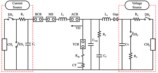
Figure 1.
Synthetic test circuit for breaking.
Table 2.
Definition of circuit components.
The representative parameter values of current and voltage sources are shown in Table 3. A circuit with R and C in series adjusts the voltage rise rate, and it is connected with a 0.5 nF capacitor (C) of the voltage divider in parallel between the two poles of the circuit breaker. The total capacitance (C), consisting of these two, determines the magnitude of arc current that enters the zero point at breaking time due to the arc-circuit interaction with the arc voltage. MS is to operate current source part, ACB is for protecting the current source part, VD is to divide voltage level, and R and C are for regulating the TRV.
Table 3.
Parameter values of current and voltage source parts.
2.2. Voltage and Current Measurement Scheme
Figure 2 shows the voltage and current measurement scheme. Voltage is measured by a voltage divider and current is measured by Rogowski. All signals are connected to the oscilloscope through a coaxial cable. The specifications of all sensors are represented in Table 4
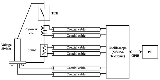
Figure 2.
Voltage and current measurement scheme.
Table 4.
Specifications of measurement sensors.
3. Current and Voltage Signal Processing at Current Zero Point
The arc current and arc voltage are required for hundreds of ns before the zero point in order to obtain the interrupting performance. Thus, the phase of current and voltage is a very important factor to improve the reliability of interrupting performance. In practice, the closer the actual zero point of the current and voltage is, the more reliable the interrupting performance result.
This study measures a current slope signal by the Rogowski coil, and it is converted into a current signal through an integral process. However, it is difficult to find the actual current zero point through this current signal since the current has a smooth shape near the current zero. Therefore, this section introduces the phase compensation method of arc current and arc voltage.
Figure 3 shows the procedure for obtaining the arc current and arc voltage signals that are synchronized from the actual measured current slope and arc voltage.The main compensation targets are the offset value included in the measurement signal, the response delay time between the Rogowski coil and the voltage divider, and the delay time due to the difference in the transmission line length. The arc current and arc voltage processed by this process should have the same zero point because the arc has the resistive characteristic. This criterion is used in the fine-tuning process at the end of the proposed procedure.
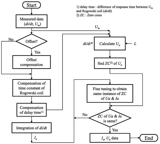
Figure 3.
Procedure of current and voltage signal processing at current zero.
4. Comparison of Interrupting Performance According to Different Arc-Quenching Gases
4.1. Interrupting Test Condition
In order to compare the interrupting performance according to the arc extinguishing medium of the circuit breaker, three types of gases—SF, g(5% Novec4710 with 95% CO), and CO(70%)/O(30%) mixture at 5.5bar, 8.0bar, and 8.0bar, respectively, were injected into the same circuit breaker. Furthermore, 90% of short-line fault (SLF90) tests are carried out for measuring both the arc current and the arc voltage then the arc conductance were calculated.
The interrupting test conditions for each arc-quenching gas are shown in Table 5. P is the absolute pressure, t is the arcing time, R and C are the circuit parameters of the TRV circuit, is the rate-of-rise of TRV (RRRV), and S/F indicates the success or failure of the interruption. The voltage divider affecting the RRRV is the same and its capacitance is given as constant 0.5 nF in all cases.
Table 5.
Test conditions of circuit breaker with arc-quenching gases.
In the study, different filling pressures and TRVs were applied to the tests of each gas in order to compare the maximum interrupting performance of g (5% Novec4710 with 95% CO) and CO(70%)/O(30%) gases with that of SF gas. The pressure of SF gas was determined to be 5.5 bar, which is typically used for SF circuit breaker. The other two gases have much lower dielectric strength than that of SF gas. Thus, the interrupting performance was analyzed by increasing the filling pressure up to 8 bar, the maximum allowable pressure of the test circuit breaker, in order to investigate how much the interrupting performance of g (5% Novec4710 with 95% CO) and CO(70%)/O(30%) follow the SF gas through pressure increase.
In addition, the boundary between the success and failure of the interruption is determined by changing the initial voltage slope of TRV. The RRRV of SF gas was determined as 10 kV/s, which is the value at the state of maximum interrupting performance of the test circuit breaker with SF gas. On the other hand, the RRRVs of g (5% Novec4710 with 95% CO) and CO(70%)/O(30%) gases were, respectively, determined as 4∼5 kV/s to find the interruption available point.
4.2. Arc-Conductance Behavior
Figure 4 shows the arc conductances of each gas as a function of interruption success and failure. The arc conductances was calculated by measured current and voltage. This is to estimate the arc conductance corresponding to the boundary between success and failure of each gas and to confirm how these boundary values relate to each extinguishing gas.
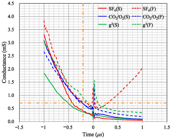
Figure 4.
Characteristics of arc conductance according to interrupting success and failure of SF, CO/O, and g gases.
KEMA has suggested a conductance range of SF before 200 ns from the current zero-cross (G200) is between 0.81 mS∼3.0 mS [20,21]. Table 6 shows the G200 characteristics for each gas obtained from the test results in Figure 4. It is verified that the 0.7 mS is determined as the boundary of success and failure of SF gas, and 0.9 mS and 0.7 mS are determined as the boundary of success and failure of g(5% Novec4710 with 95% CO) and CO(70%)/O(30%), respectively. Therefore, it is determined that critical value of the study is acceptable although it is somewhat smaller than the minimum value of the suggested range by KEMA.
Table 6.
Arc-conductance (G200) according to gases.
Increasing the TRVs of g (5% Novec4710 with 95% CO) and CO (70%)/O(30%) equal to that of SF decreases the capacitance between arc contacts. The reduced capacitance causes an increase in arc-conductance because a large current due to the arc-circuit interaction is applied shortly before the current zero-cross. As the arc-conductance increases, higher cooling power is required. Therefore, if the TRVs of g (5% Novec4710 with 95% CO) and CO (70%)/O(30%) are increased to that of SF, the circuit breaker cannot interrupt the current because it requires higher cooling power.
4.3. Interrupting Current Behavior
Figure 5 and Figure 6 show the same current traces near the current zero, based on two different time points. Figure 5 shows the current traces, based on the zero point of the arc current (I). When the interruption is successful, it is investigated that the current slope of SF gas is steepest and that of the g is the gentlest. This means that SF gas can interrupt the current under more severe current condition. Figure 6 shows the comparison of interrupting current, based on the main current is zero. The red numbers indicate interruption failures and the black numbers indicate the case of interruption success. It is confirmed that the interruption is performed at different instants in the current zero-cross of the main circuit current. In particular, the current slope approaching the current zero is smaller when the interruption is successful than when the interrupting is failed. This phenomenon makes the arc energy between the arcing contacts small and makes the interruption relatively easy. The boundary between success and failure is found to be between 1.41 A/s and 1.97 A/s.
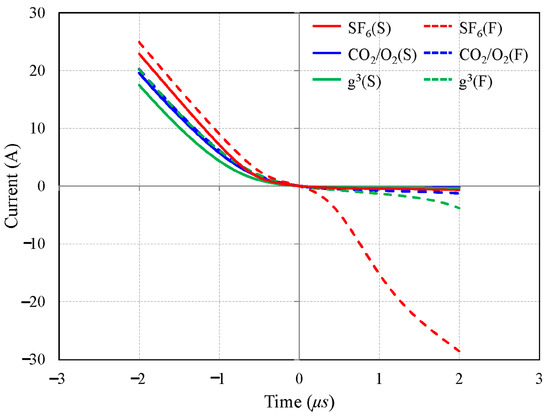
Figure 5.
Comparison of interrupting current behaviors based on current zero-cross time according to interrupting success and failure of SF, CO/O, and g gases.
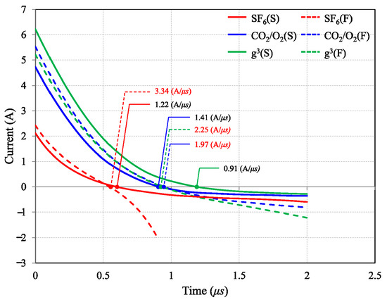
Figure 6.
Comparison of interrupting current behaviors according to interrupting success and failure of SF, CO/O, and g gases.
Figure 7 shows the several test results according to each gas. The x-axis is the current magnitude at 1 s before current zero-cross, and the y-axis is the current slope of the main current at current zero-cross. It is investigated that the red dotted line on the y-axis at 1.8 A/s|t = 0 is the critical current slope of the main current, which indicates the failure and success of the interrupting. The upper and lower parts of this critical current slope were, respectively, determined as boundary of success and failure cases, and the magnitude of the current, with the critical current slope of 1.8 A/s, is compared to evaluate the interrupting capability.
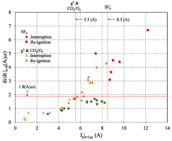
Figure 7.
Comparison of interrupting performance according to SF, CO/O, and g gases (The di/dt value at zero cross point according to change in I value at the time point of 1 s).
The current values of the corresponding extinguish gas are about 5.5 A for g(5% Novec4710 with 95% CO) and CO(70%)/O(30%) mixed gas and 8.5 A for SF. When this current value is large, it is evaluated that the extinction characteristics are excellent and the interrupting performance is good. It is noticed that the relationship between the magnitude of the current and the slope is linear in the case of g(5% Novec4710 with 95% CO) and CO(70%)/O(30%) gases otherwise the current slope remains lower than the threshold level until a certain current magnitude in the case of SF.
Figure 8 shows the post-arc current characteristics. The failed cases are indicated by dot lines. In the case of SF, the post-arc current is increased up to −28 A at 2 s when the interrupting fails. Thus, it is represented up to −4.5 A for the comparison with other post-arc current characteristics. In particular, it is verified that the post-arc current values are less than 0.5 A at 0.5 s when the interrupting is successful.
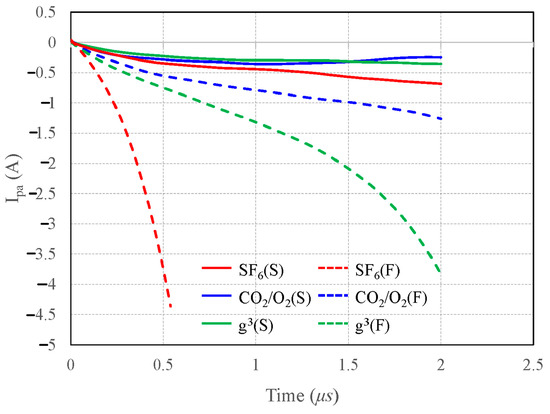
Figure 8.
Comparison of post-arc current (I) according to SF, CO/O, and g gases (post-arc current behaviors within 2 s).
5. Conclusions
The results obtained from the measurement characteristics of the current measuring device near the current zero and the breaking performance of the breaker under several test conditions are as follows.
The current measurement is performed near the zero point of the interrupting current with Rogowski coil and signal processing method is introduced to verify the suitability of the zero current measurement. Interrupting performances for SF, g (5% Novec4710 with 95% CO), and CO (70%)/O(30%) gases are compared based on the suggested processing method.
The 0.7 mS is investigated as the boundary of success and failure of SF gas and 0.9 mS and 0.7 mS are investigated as the boundary of success and failure of g (5% Novec4710 with 95% CO) and CO(70%)/O(30%) gases, respectively. It is investigated that the threshold of an arc conductance to determine the success and failure of the interrupting is slightly less than the minimum values of the region suggested by KEMA.
In addition, the main current slope at the point of interruption is analyzed to distinguish the success and failure of the interruption based on the value of 1.8 A/s independent of the type of gases and the capacitance of the arcing contacts. Finally, it is verified that the extinguishing characteristics of g (5% Novec4710/95% CO) and CO (70%)/O(30%) are similar and SF has relatively higher extinguishing characteristics than the other gases.
Author Contributions
All authors contributed to the preparation of this research. W.-Y.L., Y.-H.O. and H.-J.J. determined the concept. J.-U.J. and H.-S.O. conducted experiments. W.-Y.L. conducted writing—original draft preparation. J.-K.P. conducted investigation of introduction and writing—review and editing. Supervision was performed by W.-Y.L. and H.-J.J. All authors have read and agreed to the published version of the manuscript.
Funding
This research was supported by Korea Electrotechnology Research Institute (KERI) Primary research program through the National Research Council of Science & Technology (NST) funded by the Ministry of Science and ICT (MSIT) (20-12-N0101-54)) and the Korea Institute of Energy Technology Evaluation and Planning (KETEP) and the Ministry of Trade, Industry & Energy (MOTIE) of the Republic of Korea (No. 201712100000090).
Acknowledgments
This research was supported by Korea Electrotechnology Research Institute (KERI) Primary research program through the National Research Council of Science & Technology (NST) funded by the Ministry of Science and ICT (MSIT) (20-12-N0101-54).
Conflicts of Interest
The authors declare no conflict of interest.
References
- Zhao, H.; Li, X.; Zhu, K.; Wang, Q.; Lin, H.; Guo, X. Study of the arc interruption performance of SF6-CO2 mixtures as a substitute for SF6. Trans. Dielectr. Electr. Insul. 2016, 23, 2657–2667. [Google Scholar] [CrossRef]
- Meier, R.; Kneubuhl, F.K.; Coccioni, R.; Wyss, H.; Fischer, E.; Schotzau, H.J. Investigations of nozzle materials in SF6 circuit breakers. IEEE Trans. Plasma Sci. 1986, PS-14, 390–394. [Google Scholar] [CrossRef]
- Stoller, P.C.; Dolron, C.B.; Tehlar, D.; Simka, P.; Ranjan, N. Mixtures of CO2 and C5F10O perfluoroketone for high voltage applications. IEEE Trans. Dielectr. Electr. Insul. 2017, 24, 2712–2721. [Google Scholar] [CrossRef]
- Cheng, X.; Yang, P.; Ge, G.; Yao, L.; Xie, W. Investigation on dielectric recovery characteristics of CO2 gas circuit breakers with current commutation regulation. IEEE Trans. Plasma Sci. 2019, 47, 5070–5077. [Google Scholar] [CrossRef]
- Yannick, K.; Todd, I.; Philippe, P.; John, O. Green gas to replace SF6 in electrical grids. IEEE Power Mag. 2016, 14, 32–39. [Google Scholar]
- Nechmi, H.E.; Slama, M.E.A.; Haddad, A.M.; Wilson, G. AC volume breakdown and surface flashover of a 4% NovecTM4710/96% CO2 gas mixture compared to CO2 in highly nonhomogeneous fields. Energies 2020, 13, 1710. [Google Scholar] [CrossRef]
- Nechmi, H.E.; Beroual, A.; Girodet, A.; Vinson, P. Fluoronitriles/CO2 gas mixture as promising substitute to SF6 insulation in high voltage applications. IEEE Trans. Dielectr. Electr. Insul. 2016, 23, 2587–2593. [Google Scholar] [CrossRef]
- Zhang, B.; Uzelac, N.; Cao, Y. Fluoronitrile/CO2 mixtures as an eco-friendly alternative to SF6 for medium voltage switchgears. IEEE Trans. Dielectr. Electr. Insul. 2018, 25, 1340–1350. [Google Scholar] [CrossRef]
- Stoller, P.C.; Seegr, M.; Iordanidis, A.A.; Naidis, G.V. CO2 as an arc interruption medium in gas circuit breakers. IEEE Trans. Plasma Sci. 2013, 41, 2359–2369. [Google Scholar] [CrossRef]
- Xu, M.; Yan, J.; Liu, Z.; Geng, Y.; Wang, Z. Simulation of the decomposition pathways and products of perfluoronitrile C4F7N (3M:Novec4710). In Proceedings of the International Conference on Electric Power Equipment-Switching Technology, Xi’an, China, 22–25 October 2017. [Google Scholar]
- Chen, L.; Widger, P.; Kamarudin, M.S.; Griffiths, H.; Haddad, A. CF3I gas mixtures: Breakdown characteristics and potential electrical insulation. IEEE Trans. Power Deliv. 2017, 32, 1089–1097. [Google Scholar] [CrossRef]
- Xiao, A.; Owens, J.G.; Bonk, J.; Zhang, A. Environmentally friendly insulating gases as SF6 alternatives for power utilities. In Proceedings of the International Conference on Electrical Materials and Power Equipment, Guangzhou, China, 7–10 April 2019; pp. 42–48. [Google Scholar]
- Li, Y.; Zhang, X.; Zhang, J.; Xiao, S.; Xie, B.; Chen, D.; Gao, Y.; Tang, J. Assessment on the toxicity and application risk of C4F7N: A new SF6 alternative gas. J. Hazard. Mater. 2019, 368, 653–660. [Google Scholar] [CrossRef] [PubMed]
- Tian, S.; Zhang, X.; Cressault, Y.; Hu, J.; Wang, B.; Xiao, S.; Li, Y.; Kabbaj, N. Research status of replacement gases for SF6 in power industry. AIP Adv. 2020, 10, 050702. [Google Scholar] [CrossRef]
- Zhong, L.; Wang, J.; Wang, X.; Rong, M. Comparison of dielectric breakdown properties for different carbon-fluoride insulating gases as SF6 alternatives. AIP Adv. 2018, 8, 085122. [Google Scholar] [CrossRef]
- Li, X.; Guo, X.; Zhao, H.; Jia, S.; Murphy, A.B. Prediction of the critical reduced electric field strength for carbon dioxide and its mixtures with copper vapor from Boltzmann analysis for a gas temperature range of 300 K to 4000 K at 0.4 MPa. J. Appl. Phys. 2015, 117, 143302. [Google Scholar] [CrossRef]
- Guo, Z.; Liu, S.; Pu, Y.; Zhang, B.; Li, X.; Tang, F.; Lv, Q.; Jia, S. Study of the arc interruption performance of CO2 gas in high-voltage circuit breaker. IEEE Trans. Plasma Sci. 2019, 47, 2742–2751. [Google Scholar] [CrossRef]
- Uchii, T.; Hoshina, Y.; Kawano, H.; Suzuki, K.; Nakamoto, T.; Toyoda, M. Fundamental research on SF6-free gas insulated switchgear adopting CO2 gas and its mixtures. In Proceedings of the International Synposium on EcoTopia Science (ISETS07), Nagoya, Japan, 23–25 November 2007. [Google Scholar]
- Chen, Z.; Niu, C.; Zhang, H.; Sun, H.; Wu, Y.; Yang, F.; Rong, M.; Xu, Z. Investigation on the reduced critical breakdown field of hot CO2 gas and CO2-based mixtures. In Proceedings of the International Conference on Electric Power Equipment–Switching Technology (ICEPE–ST), Pusan, Korea, 25–28 October 2015. [Google Scholar]
- Smeets, R.P.P.; Kertesz, V. A new arc parameter database for characterization of short-line fault interruption capability of high-voltage circuit breakers. In Proceedings of the CIGRE, Paris, France, 27 August–1 September 2006. A3-110. [Google Scholar]
- Smeets, R.P.P.; Kertesz, V.; Nishwaki, S.; Suzuki, K. Performance evaluation of high-voltage circuit breakers by means of current zero analysis. In Proceedings of the IEEE/PES Transmission and Distribution Conference and Exibition, Yokohama, Japan, 6–10 October 2003. [Google Scholar]


Publisher’s Note: MDPI stays neutral with regard to jurisdictional claims in published maps and institutional affiliations. |
© 2020 by the authors. Licensee MDPI, Basel, Switzerland. This article is an open access article distributed under the terms and conditions of the Creative Commons Attribution (CC BY) license (http://creativecommons.org/licenses/by/4.0/).