Article

Offshore Wind Farm Black Start Service Integration: Review and Outlook of Ongoing Research

by
Daniela Pagnani
1,2,*,
Frede Blaabjerg
2,
Claus Leth Bak
2,
Filipe Miguel Faria da Silva
2,
Łukasz H. Kocewiak
1 and
Jesper Hjerrild
1
1
Electrical System Design and Grid Integration, Ørsted Wind Power, 2820 Gentofte, Denmark
2
Department of Energy Technology, Aalborg University, 9220 Aalborg, Denmark
*
Author to whom correspondence should be addressed.
Energies 2020, 13(23), 6286; https://doi.org/10.3390/en13236286
Submission received: 25 September 2020 / Revised: 19 November 2020 / Accepted: 26 November 2020 / Published: 28 November 2020
(This article belongs to the Special Issue Wind Farm Control Systems: Concepts and Structures)

Abstract

:
A review of the ongoing research on black start (BS) service integrated with offshore wind farms (OWFs) is presented in this paper. The overall goal is to firstly gain a better understanding of the BS capabilities required by modern power systems. Subsequently, the challenges faced by OWFs as novel BS service providers as well as an outlook on the ongoing research which may provide solutions to these are presented. OWFs have the potential to be a fast and environmentally friendly technology to provide BS services for power system restoration and, therefore, to ensure resiliency after blackouts. As a power electronic-based system, OWFs can be equipped with a self-starter in the system in order to perform BS. The self-start unit could be a synchronous generator (SG) or a power electronic unit such as a grid-forming (GFM) converter. Preliminary BS studies performed in PSCAD/EMTDC are presented in a simplified OWF system via an SG as the self-start unit. Consequently, technical challenges during the BS procedure in an OWF benchmark system are outlined via theoretical discussions and simulations results. This is useful to understand the threats to power electronics during BS. Finally, the most relevant GFM strategies in the state-of-the-art literature are presented and their application to OWF BS is discussed.

1. Introduction

Recent developments in modern power systems have been characterised by the gradual replacement of conventional generation, using mainly synchronous generators (SGs), with renewable-based generation interfaced by power electronic converters. Consequently, this has resulted in new challenges with the resiliency and planning of operations. Among renewable energy sources, offshore wind is projected to increase substantially in the next decades, with the total installed capacity growing from 23 GW in 2018 to 228 GW in 2030 and almost 1000 GW in 2050 [1].
Power system resiliency is a concept that has emerged in the last decades. Its definition concerns the capability to adapt to actual or potential contingencies in the way of preparing and planning for or conversely recovering from any type of contingency [2]. As opposed to only power system reliability, in resiliency, the focus is on power system services [3,4,5]. Recently, several total/partial shutdowns occurred around the world, which caused serious societal impacts and economic losses. A relevant example is the South Australian blackout on 28 September 2016, which was a large-scale power outage resulting from storm damage to the transmission network. Almost the entire South Australian state was blacked out, affecting approximately 850,000 customers [6]. The original restoration strategy relied on Quarantine Power Station, a thermal power plant, to provide contracted auxiliary supplies to the nearby Torrens Island Power Station. Due to technical issues, Quarantine Power Station was not able to provide this service. Additionally, the backup service provider, Mintaro Power Station, was also unavailable due to a technical fault. Given these circumstances, the system operator proceeded with the planned restart of the system using solely the Heywood Interconnector [6]. This example shows that this type of event, even if highly unlikely to happen, is quite impactful. Furthermore, the actual restoration process and time duration tend to be unpredictable.
As the socioeconomic consequences of a blackout increase exponentially with its duration, it is critical to get the system back to normal operation as soon as possible [7]. Restoration of the system after a blackout can be done via a top-down strategy, i.e., using interconnections with other zones, or alternatively using a bottom-up strategy, which involves using assets within the blackout zone in re-energisation [8]. Considering the South Australian event, an example of the former is the Heywood Interconnector while examples of the latter are the Quarantine and Mintaro Power Stations, which act as black start (BS) units. In terms of bottom-down restoration, the restoration time can be reduced by having more available BS units. Distributed resources with BS capability could increase flexibility in the system by having more BS service providers which can work together and complement each other to increase service availability [9]. In the future, distributed BS service providers could also prepare and ramp up simultaneously to achieve higher BS capacity. Thus, BS is critical in modern power system restoration strategies and can be adapted to new solutions.
In this context, offshore wind farms (OWFs) show potential as innovative BS service providers. No OWFs in the world provide BS yet though, and this novel type of BS unit needs special focus as its network configuration is new in power system restoration. Due to the presence of submarine cables, a nonnegligible shunt capacitance is introduced to the system and this shunt capacitance might excite low natural or resonant frequency [10]. Additionally, this might also be an issue for reactive power compensation and voltage control in the initial phase of restoration. Furthermore, system transformers represent a source of harmonic currents, as during initial energisation, these might cause transient inrush currents with all harmonics. Consequently, a sustained overvoltage may be produced if one of the harmonics in the transformer current excites the resonance of the system [10]. Moreover, the switching operations needed in this type of event may produce transient overvoltages which need to be controlled to avoid equipment damage and malfunction [11]. Therefore, it is necessary that the self-start unit in the OWF can handle these serious transient phenomena, with an ad hoc strategy along with the wind turbines (WTs) of the OWF. This self-start source can be a conventional SG or a power electronic-based converter with self-start capabilities, such as a grid-forming (GFM) converter. A way of avoiding major energisation transients is to soft charge the system. Soft charging is a method where the power electronics are used to control the energisation process and slowly ramp up the system voltage as the cable network is charged. Compared to sequential energisation of the single devices, soft charging has the advantage of reducing the transient phenomena.
Some research on the topic of OWF BS has already been developed; however, no overall state-of-the-art on OWF BS was found. In [12], a BS strategy from OWFs was presented which considers four different GFM control topologies and applies these only to WT BS. The paper does not consider that there are different ways that an OWF could be able to perform a BS, such as a SG or other sources equipped with a GFM converter. In recent years, researchers have pursued the concept of GFM as an alternative robust converter control in weak grids [13], and there are several applications which are suitable for OWFs, such as GFM WTs and battery energy storage systems (BESSs). In [14], a comprehensive overview of different GFM converter control strategies is presented; however, no applicability is discussed. An extensive review of different methods to implement GFM-type virtual synchronous machine (VSM) control is presented in [15]. These are assessed and compared on a small benchmark system without considerations for OWFs. Furthermore, the focus is only on VSM-type GFM control. Therefore, the objective of this paper is to highlight the different possibilities which can be implemented in OWFs to provide resilient BS and to discuss different solutions to use GFM converters.

2. Black Start by Offshore Wind Farms

2.1. Definition and Scope

BS is the procedure to restore the electrical network from a total or partial shutdown without relying on the external transmission network [16]. Conventional BS service providers are hydroelectric power plants and thermal power plants provided by SG sets, larger gas turbines, or aero-derivative gas turbine generators [17,18,19,20,21,22]. These are characterized by long start-up times, which may delay the restoration process. Furthermore, as future global goals aim at reducing the use of fossil fuels and its associated CO2 emissions, these conventional fuel-based power plants are often taken out of operation. In addition to environmental concerns, economic discussions support the integration of new BS service providers [23]. BS costs have been rising steadily as the costs associated with keeping large generators on standby continue to increase, a trend which is predicted to continue [23]. Developing solutions to allow nonconventional technologies to participate in the BS market can have substantial benefits to consumers financially, such as lower costs and increased competition [23]. Therefore, the integration of a large volume of renewable energy sources as BS providers introduces new opportunities in restoration planning. OWFs can play a key role in future restoration strategies at the transmission level. Their large capacity and renewable-based technology can be exploited to implement a fast and environmentally friendly BS procedure. In novel restoration strategies, OWFs have the potential for BS, to work in island mode, and to contribute to the restoration strategy, whereby the OWF itself can be regarded as the BS service provider. Once a self-start unit in the wind power system is energised, the whole or a part of the OWF will be energised. The OWF thus works in island operation, using local generation to balance its load requirement as a wind farm (WF) power island. After the BS phase, power system restoration itself is the actual procedure of energising the transmission network from a state of no power to a state of fully normal operation comprised of all loads and generation units. At this stage, the OWF has formed a BS power island, having energised its system, part of the transmission network, and an aggregation of loads, commonly referred to as block loads. After establishing a BS power island, the synchronization with other energised islands of the transmission network will take place. Finally, the transmission network will be fully restored [23]. These stages are illustrated in Figure 1.
Island operation of an OWF itself is also important when an offshore WT is out of power for more than one day since threats to its integrity may emerge, for example, moisture damage in the nacelle of the WT due to low temperatures and condensation or due to icing up of measurement equipment. All these threats result in the use of external/mobile auxiliary power units to supply the WTs with emergency power for auxiliary loads and components. The use of these auxiliary units can be reduced or totally avoided since OWFs are able to BS and can produce power to sustain themselves if there is wind, which is often true for offshore systems [24]. ENTSO-E, the European transmission system operators (TSOs) organization, included BS and island operation as optional requirements in their EU network codes for both high-voltage alternating current (HVAC) and high-voltage direct current (HVDC)-connected OWFs already in 2016 [25,26]. Furthermore, different TSOs propose to research the BS capabilities of renewable sources, including OWFs [27,28,29]. The provision of BS by OWF operators also represents an additional revenue stream paid by the TSO.

2.2. Black Start Requirements and Challenges

Nowadays, BS from nonconventional technologies is not actually implemented. In current grid requirements, BS requirements do not consider OWFs as a source. Nevertheless, some TSOs are exploring new possible sources of BS [23,30], which has resulted in an extended set of requirements being proposed by National Grid Electrical System Operator (ESO) and ELIA, i.e., the British and Belgian TSOs, respectively. These requirements are explained in [31] and are shown in Table 1.
Among these requirements, the most trivial is self-start. This implies the need to implement a unit able to self-start in the design of OWFs, in other words, BS. Other requirements address the service availability, which determines the time which the BS service provider must be available to deliver the service. Further requirements are voltage and frequency control, short-circuit level following a system disturbance, and inertia provision. It is relevant to notice that this inertia requirement has been introduced for nonconventional technologies and as these are characterized by a power-electronic interface, they do not provide inertia naturally. Therefore, this new requirement targets BS sources to provide virtual/real inertia.
Several challenges arise from implementing BS in OWFs, as common OWF designs do not consider the capability of restoring a black network, with the self-start capability being the most trivial, as the main point to be understood is whether the OWF can energise its own system, comprised of WTs, long HVAC cables, transformers, and other equipment by itself. OWFs are usually only equipped with grid-following (GFL) WTs, which are only able to deliver power to an energised grid [33]. Therefore, a first challenge is to implement a self-start unit in the OWF. There are several configuration strategies for implementing a self-starter in the WF design, as presented in [31], which could be an SG, powered by diesel or biomass, or a GFM unit, if power-electronic-based. GFM converters are a specific type of grid-connected inverters, which can set the voltage magnitude and phase reference, thus forming the local grid [33]. An overview of different methods and their characteristics to achieve BS in OWFs is presented in Table 2.

3. Preliminary Offshore Wind Farm Black Start Studies

In this section, preliminary BS studies on an OWF system will be presented with the intention of describing the system and its associated challenges. Simulations for BS studies enable the identification of overvoltages that might take place because of switching operations. In order to understand the challenges introduced by a system operation such as BS in OWFs, preliminary system studies are presented. It is important to conduct such type of studies as BS operation requires many switching operations, which focus on switching overvoltages (SOVs). SOVs might be a source of failures in OWF components [34]. Furthermore, unwanted resonances can cause overall WF stability and performance issues, e.g., unwanted harmonic excitation and amplification. This makes the system particularly sensitive in a scenario such as BS.

3.1. System Description

The proposed system is inspired by the current large OWF design. Its basic representation is modular; therefore, the power capacity can be expanded. One module is highlighted in the dashed rectangle. Currently, large OWFs have a capacity around 1.0 GW. Soon, it is expected that the size can be doubled. A basic OWF system is presented and shown in Figure 2. In a typical OWF layout, reactive power compensation devices and filters are also present, which are not considered for these preliminary studies. For the sake of simplicity to outline preliminary key results, a simplified version of the presented system has been modelled and shown in Figure 3.
This system consists of a single module structure, for which the models are inspired from real OWF components. This preliminary study on the dynamic behaviour of a simplified OWF system during island operation is accomplished by means of theoretical considerations and simulations. This system has been modelled in PSCAD/EMTDC. All the implemented models and parameters are inspired by real-life devices in modern OWFs. In the model, the WTs are constant power (PQ) loads to take into consideration their internal loads when these are first energised. The total load is equal to 6 MW and considers the energisation loads of WTs such as heaters, dehumidifiers, lights, and no-load losses in WT transformers for a cluster of 55 new-generation offshore WTs, thus representing 1% circa of rated power, which is 440 MW. The WTs are connected to an offshore 34-kV collector bus, which in turn is connected to a 220/34 kV, 240 MVA transformer. For all transformers in the system, the saturation characteristics have been implemented. The Cu XLPE 1600 mm2, 220-kV HVAC export cable is a submarine cable which is only 5-km long in order to simplify the system and to omit reactive power compensation stations for this preliminary study. This is modelled as a frequency-dependent component as it is useful for studies wherever the transient or harmonic behaviour of the cable is relevant. The onshore submarine cable end is connected to a 400/220 kV, 475 MVA onshore autotransformer that connects the OWF to the onshore grid, which is not present in this scenario to first simulate the BS of the OWF working in island mode. At the same bus, the self-start unit is connected, which is a 120 MVA, 13.8 kV diesel generator connected to the 220-kV bus via an ideal 120 MVA, 220/13.8 kV transformer. This is chosen to represent a conventional and large BS unit, which could be able to energise the OWF system. More details on the components are given in Appendix A.

3.2. Simulation Results

The energisation sequence is made up of steps in which breakers close to energise the next part of the OWF once the previous part has reached steady-state conditions. The total simulation time is 5 s. Firstly, the self-start unit; subsequentially, the export cable, offshore transformers, and WT loads branches separately; and finally, the onshore transformer to interface the transmission grid are energised. The results from the three-phase current and voltage waveforms seen from the SG, from the point where a scope is drawn in Figure 3, are shown in Figure 4.

3.2.1. Energisation of the Submarine Cable

As it can be seen from Figure 4, the simulation is started with the SG working in steady state at no load. The first breaker operation is set to close BRK2 at t = 0.1 s, which energises the submarine cable. The switching operation is performed with point of wave (POW) in order to minimise the energisation transient as the existence and magnitude of the inrush current depend on the voltage value at the energisation instant. Therefore, the three single-phase breakers close each phase when the voltage waveforms are at zero crossing. This single-pole operation reduces the transients, which are shown in Figure 5. The switching operation causes an increase in voltage reaching 1.06 pu at 0.1575 s due to the charging currents. However, this is the highest overvoltage seen in the system during energisation. The high spikes seen in the current also suggest a high inrush. Nevertheless, the higher peak reaches 0.21 kA at 0.103 s in phase B, which is at the secondary peak of the generator transformer. This represents approximately half of the SG-rated current on the transformer primary side. As it can be seen from Figure 5a, the currents present a notable distortion. During these transients, harmonic components are excited; this is due to the fact that the system presents in series the SG, transformer, and submarine cable, which have both inductive and capacitive reactive components being charged during the transient and interacting with each other.

3.2.2. Energisation of the Offshore Branches

The first switching transient decays after 0.6 s, and the breaker BRK3 is closed at 0.8 s. Also, in this operation, POW is applied, and the switching instants occur when the voltage is at peak magnitude. This is because the flux and voltage electromagnetic vectors are aligned at that phase. In this system simulation, the effect of remanence is not accounted for; however, assuming that the BS is soon after the blackout, it might be relevant to account for it in future studies. This is particularly interesting as, during a BS or light-load circumstances, there could be the need to energise a transformer located remotely against minimum generation via a submarine cable, as in this case. This configuration may create a low system-resonant frequency, which could be excited by one of the harmonic components of the inrush current of this transformer, which may excite the resonant frequency of this system and result in transient overvoltages that could possibly last for several periods. In Figure 6, this transient is zoomed.

3.2.3. Energisation of the Onshore Transformer

A situation similar to cable energisation is found when breaker BRK1 is closed at t = 1.5 s and the onshore transformer is energised after having the offshore system energised. This is shown in Figure 7.

3.2.4. Application of Soft Charging

As it can be seen, these switching operations bring important transients to the system during BS and island operation, even with the use of auxiliary techniques such as POW. One solution to avoid these transients and to keep the resiliency of the system is to implement soft charge in the self-starter. Maintaining the same system structure seen in Figure 3, all the breakers are closed. The SG can perform a soft charge if supplied by an electronic voltage controller, which ramps up the SG voltage slowly. This is shown in Figure 8. As shown, the energisation transients are avoided, reducing the stress on the OWF components. It should be noted that this procedure is not commonly implemented; therefore, more research in this area is needed.

4. Grid-Forming Control for Offshore Wind Farm Black Start

As discussed in the previous sections, a first challenge to address in OWFs is the inclusion of a unit able to BS. There is a growing research interest in GFM control strategies as, when applied to OWFs, this will allow island operation and BS service integration. GFM converters are defined as converters behaving as ideal voltage sources having voltage amplitude v* and angular frequency ω* controlled in closed loop. As presented in [31], this could be suited to different inverter-based resources in the OWF, such as HVDC-connected OWFs, BESSs, and WTs. Only type 3 and type 4 WTs are considered due to their converter interface, where the GFM control can be applied. The motivation behind researching GFM converters in this area is to avoid the deployment of conventional units, i.e., SGs, which will emit CO2 due to the use of fuels such as diesel or biomass. One of the first classifications of GFM control has been presented in [33], which focuses on control structures for AC microgrids. In order to understand the most suitable option of a GFM control, an overview of different strategies is presented.
A GFM converter synchronization system can work on both island and grid-connected operations. Besides the purpose of BS and island operation, GFM control may also improve the stable operation of the converter independently of short-circuit level of the grid [14]. Furthermore, GFM control can provide an inherent frequency response to system events. GFM converters can properly ride through cases of system split thanks to their capability to withstand a high rate of change of frequency (RoCoF) [14]. Additionally, advanced control loops can be implemented on the basic of GFM structures in order to provide higher performance such as inertia emulation and short-circuit infeed [14]. In this way, GFM converters may satisfy the BS requirements, as illustrated in [31]; further research into this is necessary. Several different control topologies have been presented in the state-of-the-art of GFM converters. In the following, a review of the most relevant research with respect to popularity and applicability to OWF BS is presented.

4.1. Basic Grid-Forming Control Method

The basic control structure of GFM control consists of two cascaded loops, as shown in Figure 9 [33]. Figure 9 shows an example where the controller applies two synchronous controllers in the dq frame. The control system inputs are the amplitude v* and the angular frequency ω* of the voltage that the converter forms at the point of common coupling (PCC). The reference values v* and ω* need to be calculated by a higher-level controller or via lookup tables [33]. Voltage control is performed in the external loop, where the error between the measured voltage magnitude vabc and the reference voltage v* is the input to the current controller, for which the output establishes the current reference i*. Subsequentially, the reference signal uabc, is fed to the pulse-width modulation (PWM) block. Filters are commonly used, here, represented as a series filter inductor Lf and a shunt filter capacitor Cf. Usually, in industrial applications, these power converters are fed by stable DC voltage source VDC, for example, driven by a BESS, fuel cells, or another source. In the following section, the source of VDC is not discussed.
GFM converters can apply both the dq synchronous as well as the αβ stationary reference frame [35,36]. In Figure 9, the transformation in dq frame is shown as an example.

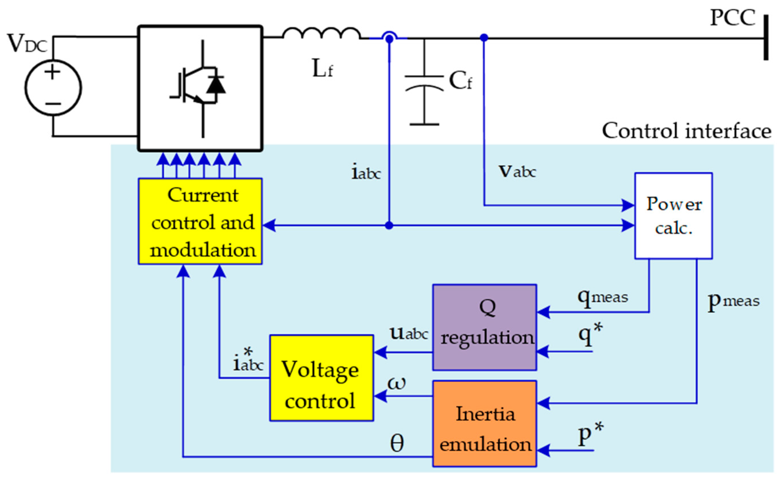
4.2. Droop-Based Control

To regulate the active P and reactive power Q provided to the grid, droop control is used for GFM strategies [37]. These are also defined as voltage-source grid-supporting converters [33]. The implementation shown in Figure 10 is taken from [33].
Droop control mimics the inherent regulation of SGs in grid-connection mode. Droop-based GFM control can be implemented both in islanded and grid-connected operations without any other type of GFM converter connected in the system [33].
Droop control for the GFM strategy emerged as an alternative to different current sharing strategies for small-rated parallel converters, such as average-load sharing, centralised controllers, or master–slave [38]. These types of strategies exploit high-bandwidth communication channels for control coordination. Communication requirements can be tricky for large systems such as OWFs in a situation such as BS. During BS, many devices in the system might be out of service. Therefore, fast and reliable communication might be challenging. Droop control is thus used to achieve power management in a decentralized manner. This implementation uses the forward droop equations as seen:
vg = (Q* − Qmeas)kv + v*
ωg = (P* − Pmeas)kf + ω*
where kv and kf are the voltage and frequency droop coefficients, vg and ωg are the actual grid voltage grid angular frequency, and v* and ω* are the reference grid voltage and grid angular frequency, respectively. The parameters P* and Q* are the reference active and reactive power, while Pmeas and Qmeas are the measured active and reactive power, respectively. A low-pass filter is applied to the measured active and reactive power before they are used in the control to avoid oscillations and disturbances in the measurements and to thus stabilise the control loops. The 1st-order low-pass filter with cutoff angular frequency ωf is implemented before the power calculation stage.
An alternative to this basic strategy is introduced having an angle feedforward proportional to the active power flow. This is shown in Figure 11.
This was first proposed in [39] and more recently in [14] and is defined as Selfsync. In Figure 5, the low-pass filter is not shown as considered included in the power calculation block. Furthermore, the voltage and current controllers are represented in single blocks and this style will also be adopted in the following figures.
This modification of the basic droop structure will improve the controller dynamics. The structure for V/Q droop remains untouched, while the P/f droop is a combination of the term k’f (P* − Pmeas), which is feed forward. According to the invention, active power oscillations between the inverters are avoided in this way [28]. The output of the droop controls is then fed to a cascaded voltage and current controllers, as in previous implementations.
A disadvantage of droop structures is the fact that droop strategies can cause a steady-state error [40]. This could be corrected by designing a supplementary control.

4.3. Virtual Synchronous Machine

With the intention of imitating the inertia provision by SGs, virtual synchronous machine (VSM) control has been introduced. This is a popular type of implementation which has been implemented in different applications and proven successful for inertia emulation [41,42]. Nevertheless, not all implementations of VSM are GFMs. The structures of VSM considered here are only GFMs for BS. There are several implementations of this type of control, and their main core is in the application of some form of the swing equation as shown in (3).
Tm − Te − kdΔω = J dω/dt
where ω is the angular frequency, Tm and Te are the mechanical and electromagnetic torques respectively, kd is the damping factor, and J is the moment of inertia, which will not influence the steady-state operation but has a strong impact on the dynamics. A large J implies more energy released or absorbed during the disturbance and a stronger ability for frequency support.
There are varying levels of model complexity, ranging from simple models which implement only the swing equation, to 9th-order models [15]. High-order models can be directly implemented with the same parameters as a real SG. An advantage is the fact that these controller parameters can be tuned and updated according to a specific application by a software modification, as controllers do not have the same physical constraints as the SGs. However, as previously explained, power electronic converters may present other challenges.
Nevertheless, it has been seen that, mainly for high-order models, this kind of control might tend to be numerically instable [43], the origin of which is not yet clear. In fact, it is not known whether this problem is intrinsic in the models or is merely due to numerical matters which can be solved by applying a proper integration method [43].
In [43], a classification of the main types of VSM implementations is made. These groups are distinct in current reference, voltage reference, and power reference as output reference from the VSM. The first two groups are GFM and will be presented further.

4.3.1. Current References from the SG Model

The current reference iabc* can be the output of the full- or reduced-order SG model. As the measured voltage can be the input of a SG model to compute the resulting currents, this approach allows a rather simple configuration in high-order SG models. The first proposal of this type of VSM implementation is the VISMA [44]. A simplified representation is shown in Figure 12. To have the necessary performance, limitations and saturations can be embedded directly on the reference value.

4.3.2. Voltage References from the SG Model

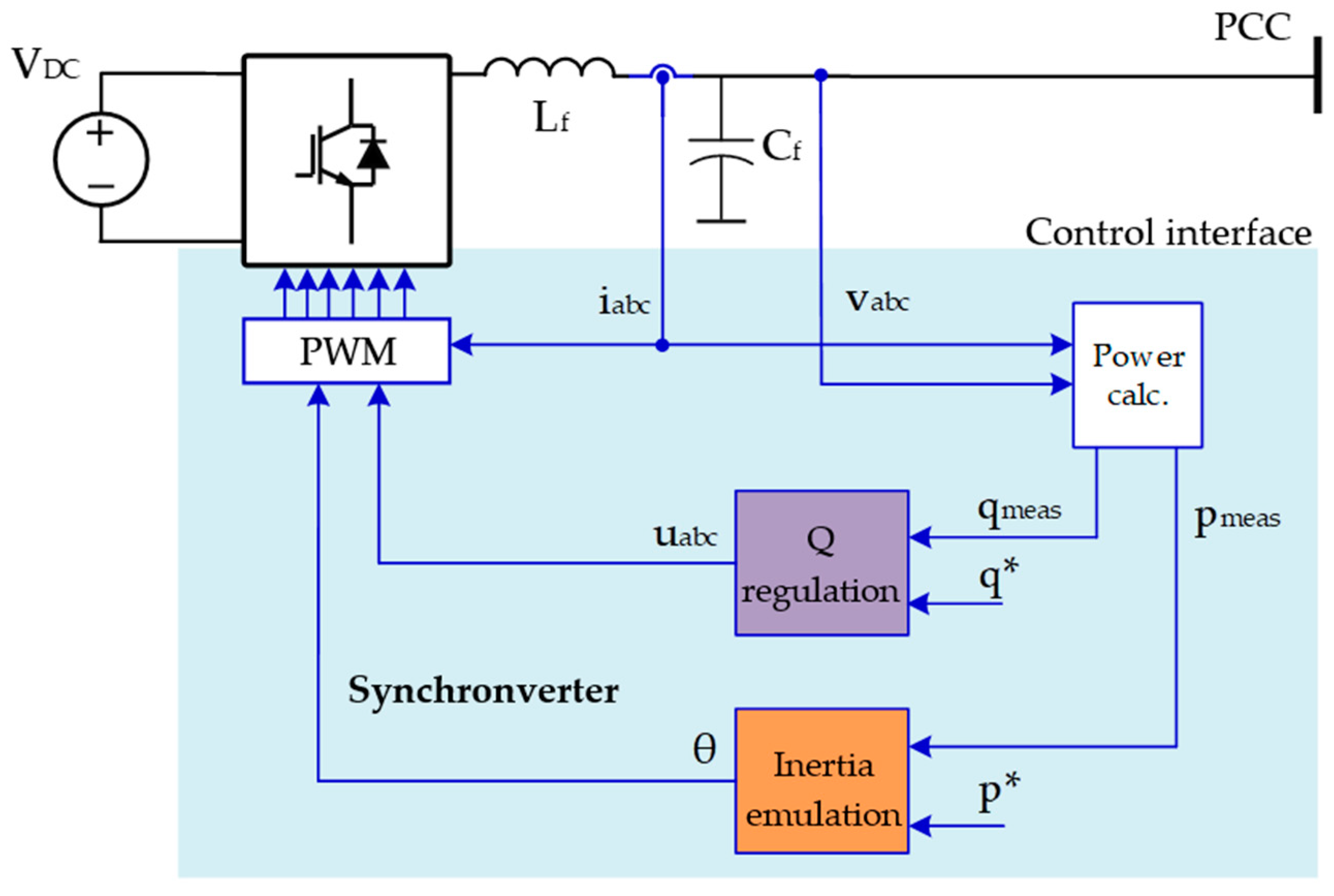
A different type of VSM implementation exploits a voltage reference output from the SG model. In [45], these two VISMA concepts are compared. When applying reduced-order models, the active power depends both on the virtual inertia and the phase angle, which can be calculated from the swing equation. At the same time, the reactive power can be controlled separately. An example considers the 5th-order SG model of a round rotor machine which does not include damper windings for the rotor. As the voltage magnitude and phase angle are sent directly to the PWM block, this can be considered the most direct implementation of the VSM concept. The Synchronverter control discussed in [46] and several other recent publications [46,47,48,49,50,51] apply this strategy, which is shown in Figure 13.
A disadvantage of this implementation is not having an explicit current signal in order to implement overcurrent protection. A similar approach with enhanced controllability is shown in Figure 14. Higher flexibility for protection is obtained since both voltage and current can be kept within a defined range [52,53]. This is because a classical cascaded control is applied where voltage output is the reference for an external voltage loop with an internal current control. According to [14], the optimal tuning of these controllers is necessary in this type of VSM control.
It should be noted that these control strategies of the VSM with voltage reference as an output of the SG model and droop-control show some similarity. In [43], the equivalence between this implementation of VSM and droop control is demonstrated; droop gain kP is the inverse of damping gain kd in the swing equation. Furthermore, the 1st-order low-pass filter on the active power, as shown in Figure 10, serves an analogous role as the emulated inertia. Consequentially, a droop controller can be tuned to replicate the SG small-signal characteristics.
An aspect common to all of SG emulation strategies is their short-circuit capability. In [54], a virtual resistor is added to a VSM 3rd-order model to obtain an enhanced short-circuit capability. This implementation can be applied for the system to perform more similarly to a conventional BS unit. This may require further investigations, especially related to application to a power-electronic-dominated system such as OWFs.

4.4. Power-Synchronization Control

Another consolidated and popular GFM structure is the power synchronization control (PSC), shown in Figure 15. The PSC control structure was initially presented in [55] and refined in [56]. It was developed originally for HVDC systems to cope especially with weak grids. In this approach, active power is used for synchronization as in the VSM. Nevertheless, the main difference is that the PSC loop (PSL) gets the phase angle directly by a single integration of the power difference. This differs from the swing equation in VSM, where the power difference drives the virtual rotor speed dynamics, which is then changed to an electrical angle by a double integration. Due to one less integrator, PSC has a higher stability margin. The angle θ is estimated and fed to the dq and αβ blocks in order to implement the transformation. On the other hand, the current at the fundamental frequency is not controlled, as the PSL contrasts it. Nevertheless, in power electronics, the current always needs to be limited to avoid component damage and a current limiter block is implemented, which receives a voltage signal and generates the udq* signal to be fed to the converter.
However, due to inherent steady-state droop, outer droops are needed for paralleling multiple GFM units. Moreover, neither virtual inertia nor damping are inherent in the design. Another disadvantage of PSC is represented by the fact that it needs a phase-locked loop (PLL)-based standard control as backup in case of grid-faults and initial phase synchronization.

4.5. Distributed PLL

The distributed PLL (dPLL) control structure is based on [57]. This was originally applied to GFM WTs and was developed for diode-rectifier (DR)-based HVDC-connected OWFs. Based on the voltage reference signal coming from the offshore converter, this type of controller generates the d-axis voltage reference from the active power flow from offshore. At the same time, based on the reactive power required by the DR unit, the frequency is regulated by a Q droop. Thus, dPLL can be said to be a voltage source controlled with Q-f, P-V coupling. This is shown in Figure 16.
This approach exploits a PLL but does not set the q-axis voltage reference to 0 as usually done. Instead, a frequency control loop is embedded in the q-axis to use the output of the Q-f droop-controller. In this way, frequency deviations can be expressed by the output of the PLL.
In [57], it is used to successfully provide GFM WT start-up in sequence and synchronization of offline WTs during connection automatically via the plug-and-play capability to implement frequency controllability. This is used to supply the reactive power required to energise the passive components of the system and to ramp up the voltage. In this way, active power can finally be delivered to an onshore grid. Nevertheless, the study includes only the application of dPLL to WTs in a DR-HVDC system in order to energise the offshore grid. Thus, it implements the self-start of the WT system and its synchronization to an energised onshore AC power system. Therefore, the energisation of an export cable and an onshore converter has not been investigated, which is an important operation for a BS unit.

4.6. Direct Power Control

Direct power control (DPC) represents another relevant control for OWF BS. DPC was introduced by [58], in which instantaneous P and Q are controlled without requiring AC voltage sensors, PLL, or an inner current controller via hysteresis comparators on the power errors and a look-up table to select the best converter switching time. Since then, it has undergone many enhancements to deliver improved performance like using space vector modulation for constant switching frequency, employing sliding mode control for robustness, modelling predictive control for the multivariable case, and employing grid voltage-modulated DPC for good transient-response and steady-state performance in nonlinear systems. This implementation of DPC is a type of GFL control as, even though a PLL is not used, estimation of the output voltage gives the reference for the phase angle. A GFM variation of the DPC can be found in [56]. This is relevant as its main functionality is the ability to operate with very low short-circuit ratio (SCR), i.e., below 1.5. The control scheme is given in Figure 17, which applies a PLL that synchronises the dq frame with the grid voltage vector.
The PLL continuously detects angle deviations in the case of islanding, where the converter is feeding passive loads. Two outer loops can be identified; the former is the reactive power control with integrator time constant T, linked to the internal voltage magnitude M of the converter. The latter is the active power loop in charge of controlling the internal voltage angle θc. The angle θc is related to the PLL angle θPLL as it is the phase angle shift between these two. A PI controller with gain G and time constant J is implemented in DPC. Moreover, the measured angular frequency of the PLL ωPLL is used in order to apply a frequency droop control that adapts the active-power set point for given frequency variations. The scheme in [59] has the main characteristics of a variation of DPC shown in [60], which is applied to WTs.

4.7. Overview of Different Grid-Forming Strategies

Different types of GFM control structures have been explained. In the state-of-the-art literature, these have been applied to different devices, e.g., HVDC transmission, BESSs, WTs, and photovoltaic (PV) units, and with different purposes, such as weak grid applications and inertia emulation. Nevertheless, these all show potential to be applied to OWF for BS. In this section, a further overview is given to differentiate the controller in terms of comparison and results found in the state-of-the-art literature.
As stated, GFM control can be suitable to different devices in OWFs. The basic droop control structure has been used in [61], where a 400-MW OWF consisting of 50 WTs with GFM capabilities is used for BS of the onshore grid. In this study, practical challenges in the energisation transient have been studied via electromagnetic transient (EMT) simulations. These challenges arise from the inrush phenomena due to the large reactive loads of the OWF export system. The simulation results showed that the OWF was able to BS and energise the onshore network and block loads also in the presence of wind fluctuations. The strategy shows promising results; however, considerable distortions in the voltage and current waveforms are seen during the BS performance. Therefore, more studies are relevant to reduce the magnitude of the inrush as well as the distortions to have a resilient system in real life. Similarly, in [62], a 400-MW OWF connected by a 75-km long HVAC cable equipped with a mix of GFM and GFL WTs was applied for BS. It was shown that 25% of plant capacity droop controlled GFM was needed for stable operation during export cable energisation and block loading. This is interesting as an outstanding question regards the GFM capacity of the system. It is not clear if it is better to only use 100% GFM converters or if only a percentage of the system must be GFM. At the same time, research into the implication of performing a transition from GFM to GFL after the system is restored is needed. In [63], droop control has been applied to an AC microgrid comprised of energy storage, for example, a BESS, and PVs in order to realize an autonomous control, i.e., power management in a decentralized manner. This could be used in large OWFs as it shows flexibility in the primary energy source. The proposed control is based on active power GFM droop for the BESS and GFL droop for the PVs. The algorithm uses the frequency from the BESS to control the production of PVs maintaining its state of charge (SoC) in a defined range. At the primary control level, the main power management is implemented locally. At the secondary and further levels, stricter frequency requirements can be achieved to mitigate the steady-state error. The control solution is validated with both EMT and real-time simulations, which proved that this strategy works by adjusting the power generation from the PVs to the supply load, keeping the BESS SoC in safe limits. In practical terms, this control setup could be adapted to OWFs, where a centralized storage behaves as a GFM unit while the WTs are in GFL mode.
Specifically, for VSM, a review of VSM applied to WTs is given in [64]. For type-4 WTs with no additional energy storage, an analysis of their inertial response when controlled with VSM has been presented in [65] and it showed that these WTs have worse performance in comparison to those with additional storage. Therefore, this paper emphasizes the advantage of storage for VSM control in WTS. In [66], VSM control is implemented in type-4 WTs equipped with short-term energy storage in the DC link. The DC-link voltage is kept constant due to the additional storage unit which charges and discharges and is connected via a DC/DC converter. Similar to [63] with PVs and droop control, the VSM control of the storage unit is made of three operation ranges based on the SoCs of the energy storage. The SoC is adjusted in the range of its setpoint during normal VSM operation. If the SoC falls below the setpoint range, the control will change its maximum power point tracking (MPPT) mode. Conversely, when SoC is above the setpoint range, the power intake will be reduced, enabling pitch control.
Field tests of GFM WTs with VSM control have been presented in [41,42]. A small-scale onshore WF with 23 WTs has been compared with WTs of the same type but with GFL current control. In island mode, these WTs have been subject to dynamic load changes in an islanded system. The WTs equipped with a VSM GFM converter showed appropriate inertial response. These results will point in the direction of having a 100% GFM WT system also in normal operation, a part of BS operation.
In [15], a comprehensive overview of different VSM implementations is given. These are classified according to the order of the SG model. A comparison of the frequency characteristics is then implemented on a radial system, focusing on five different types of VSM implementation, comparing higher-order models, i.e., VISMA-based, lower-order models, and Synchronverter. The swing-equation-based model and the Synchronverter have similar frequency characteristics. When the synchronous impedance is introduced in the VSM, the system becomes more stable with a larger stability margin. For the 4th-order model, the transient impedance is active in the high-frequency domain, which leads to a smaller stability margin than that of the VSM of the 2nd-order with synchronous impedance.
The model of the VISMA-based method has the same characteristics as that of the VSM of the 2nd-order with synchronous impedance in the low-frequency domain. However, it introduces resonance at the synchronous frequency due to the differential term. A 180° phase lag is also induced at the resonant peak. The control strategies with low-order models have larger oscillations and longer settling times in response to the load and power steps as well as the grid frequency. In comparison, the other models have lower oscillations and/or lower settling times, which prove that the impedances of SG contribute to the oscillation damping.
In [67], the application of PSC is proposed for integrating a type-3-based OWF connected via a HVDC link to a weak AC grid. The control strategy is proven feasible for stable operation during steady state and contingencies such as two fault cases, i.e., located offshore and onshore. Real-time simulations are used for the entire study. This provides a window of applicability of PSC in WTs to HVDC-connected OWFs. The WTs provided by PSC may BS the WF power island from offshore. BS of the onshore grid needs to be discussed.
In [59], the control topology shown in Figure 17 is applied to a 118-bus benchmark system. EMT simulations are performed, and the results show that the proposed control can provide active and reactive power regulation, fault-ride-through capability, and the capability to operate in a 100% inverter-based grid.
In [12], a comparison of VSM, PSC, dPLL, and DPC has been applied to a 400-MW OWF connected via HVDC. It is shown that the OWF has different characteristics based on the control method used. As DPC is the most straightforward control technique with direct voltage and frequency control without any inner loops and does not have any electromechanical characteristics like inertia or damping, it results in the highest frequency swing along with the highest transient peaks. Comparatively, VSM has a lower frequency dip due to inertia emulation in its power controller, along with lower transient power peaks due to damping provided by virtual impedance. On the other hand, PSC has a higher frequency swing than VSM due to the absence of inertia emulation, but the damping provided by the voltage controller reduces the transient power peak compared to DPC. Contrary to the power-synchronization-based VSM and PSC methods, the frequency swing in dPLL is lowest, seen with no overshoot, due to the frequency controllability of the PLL-based frequency control loop, which also provides damping and reduces the transient power peak. According to this study, it is seen that all the four methods can deal with the energisation transients in a controlled manner while maintaining the stability of voltage and frequency at the offshore terminal. Therefore, these methods seem promising for future OWF BS. A comparison of these presented methods is shown in Table 3, where the main advantages and disadvantages of each are outlined.

5. Conclusions

In this paper, a thorough review on the topic of OWF BS is presented. Firstly, the motivation behind researching new types of BS sources to keep a high level of resiliency in future 100% renewable power systems is presented. Subsequently, an overview of the newly proposed power system requirements for BS is outlined. Conversely, a discussion on the need for careful selection of a self-start unit needs to be carefully given as an OWF during BS goes through a series of switching transients, inrush currents, system resonance, and overvoltages. Thereafter, these phenomena occurring during the energisation process in a real OWF BS by a SG are investigated through simulations with PSCAD/EMTDC. The results indicated that, by using a novel energisation method such as soft charge, all these adverse switching events as well as the resulting transients can be avoided. Since the GFM converter represents a novel technology which may be applied in BS service, an outlook on GFM control strategies for OWF BS is presented. Several control topologies such as VSM, droop control, PSC, etc.; different applications, such onshore WFs, PVs, microgrids, etc.; and different technologies, BESS, WTs, and so on have been investigated. As a result, there are several options available for implementing BS in OWFs. The outcome will depend on the technical performance of the system. For future work, system simulations with different GFM controls will be useful to compare conventional to novel BS sources and to design an OWF system with integrated BS capabilities.

Author Contributions

Conceptualization, all; methodology, all; formal analysis, all; investigation, D.P.; writing—original draft, D.P.; writing—review and editing, all; supervision, F.B., C.L.B., F.M.F.d.S., Ł.H.K., and J.H. All authors have read and agreed to the published version of the manuscript.

Funding

This work is part of a PhD project funded by Ørsted Wind Power and Innovation Fund Denmark, project 9065-00238.

Acknowledgments

This PhD project is supervised by Ørsted Wind Power and Aalborg University.

Conflicts of Interest

The authors declare no conflict of interest.

Appendix A

For each component modelled in the system shown in Figure 5, the details implemented in PSCAD are shown in the following tables.
Table A1. Synchronous generator data implemented in PSCAD.
Rated RMS line-to neutral voltage7.967 kV
Rated RMS line current5.02 kA
Base angular frequency314.159 rad/s
Inertia constant10 s
Iron loss resistance300 pu
Initial voltage magnitude at time 01 pu
Initial phase magnitude at time 00 rad
Table A2. Submarine cable data implemented in PSCAD.
Cable typeThree-core cable with XLPE insulation, lead sheath and wire armourNominal voltage220 kV
Cross section of CU conductor1600 mm2Lead screen cross section650 mm2
Diameter of conductor45 mmCore outer insulator2 mm
Insulation thickness20 mmCopper resistivity1.5 Ω/m
Insulation screen thickness1.5 mmXLPE permittivity2.5 F/m
Table A3. The 400/220 kV, 475 MVA transformer data implemented in PSCAD.
Transformer rating475 MVA
Winding voltage rating400/220 kV
Leakage reactance0.12 pu
No load losses0.00014 pu
Copper losses0.0015 pu
Air core reactance0.24 pu
Knee voltage1.2 pu
Magnetization current0.055%
Table A4. The 220/34 kV, 240 MVA transformer data implemented in PSCAD.
Transformer rating240 MVA
Winding voltage rating220/34 kV
Winding configurationYd
Leakage reactance0.15 pu
Eddy current losses0.0003 pu
Copper losses0.0015 pu
Inrush decay time constant1.8 s
Air core reactance0.65 pu
Knee voltage1.2 pu
Magnetization current0.03%
Table A5. Wind turbine energization loss data implemented in PSCAD.
Rated active power per load per phase1 MW
Rated reactive power per load per phase0
Rated load voltage34 kV

References

  1. International Renewable Energy Agency (IRENA). Future of Wind—Deployment, Investment, Technology, Grid Integration and Socio-Economic Aspects; IRENA: Abu Dhabi, UAE, 2019; ISBN 978-92-9260-155-3.
  2. CIGRÉ WG C4.47. Defining Power System Resilience; Electra: Paris, France, 2019; Volume 306, pp. 1–3. [Google Scholar]
  3. National Academies. Disaster Resilience: A National Imperative; The National Academies Press: Washington, DC, USA, 2012. [Google Scholar]
  4. National Academies. Improving Power System Resilience in the 21st Century; The National Academies Press: Washington, DC, USA, 2014; pp. 1–12. [Google Scholar]
  5. Clarck-Ginsberg, A. What’s the Difference between Reliability and Resilience? Stanford University: Stanford, CA, USA, 2016. [Google Scholar] [CrossRef]
  6. Australian Energy Regulator. The Black System Event Compliance Report: Investigation into the Pre-event, System Restoration, and Market Suspension Aspects Surrounding the 28 September 2016 Event; Australian Energy Regulator: Melbourne, Australia, 2016.
  7. Jain, A.; Sakamuri, J.N.; Das, K.; Göksu, Ö.; Cutululis, N.A. Functional requirements for blackstart and power system restoration from wind power plants. In Proceedings of the 2nd International Conference on Large-Scale Grid Integration of Renewable Energy in India, New Delhi, India, 4–6 September 2019; pp. 1–8. [Google Scholar]
  8. ELIA. Study on the Review of the Black Start Ancillary Services; ELIA: Brussels, Belgium, 2018. [Google Scholar]
  9. Adibi, M.M.; Martins, N. Power system restoration dynamics issues. In Proceeding of the IEEE Power and Energy Society General Meeting—Conversion and Delivery of Electrical Energy in the 21st Century, Pittsburgh, PA, USA, 20–24 July 2008; pp. 1–8. [Google Scholar] [CrossRef]
  10. Turner, R.; Smith, K. Transformer Inrush Currents. IEEE Ind. Appl. Mag. 2010, 16, 14–19. [Google Scholar] [CrossRef]
  11. Xin, Y.; Liu, B.; Tang, W.; Wu, Q. Modeling and Mitigation for High Frequency Switching Transients Due to Energization in Offshore Wind Farms. Energies 2016, 9, 1044. [Google Scholar] [CrossRef]
  12. Jain, A.; Sakamuri, J.N.; Cutululis, N.A. Grid-Forming Control Strategies for Black Start by Offshore Wind Power Plants. Wind. Energy Sci. 2020, 5, 1297–1313. [Google Scholar] [CrossRef]
  13. Matevosyan, J.; Vital, V.; O’Sullivan, J.; Quint, R.; Badrzadeh, B.; Prevost, T.; Quitmann, E.; Ramasubramanian, D.; Urdal, H.; Achilles, S.; et al. Grid-Forming Inverters: Are They the Key for High Renewable Penetration? IEEE Power Energy Mag. 2019, 17, 89–98. [Google Scholar] [CrossRef]
  14. Unruh, P.; Nuschke, M.; Strauß, P.; Welck, F. Overview on Grid-Forming Inverter Control Methods. Energies 2020, 13, 2589. [Google Scholar] [CrossRef]
  15. Chen, M.; Zhou, D.; Blaabjerg, F. Modelling, Implementation, and Assessment of Virtual Synchronous Generator in Power Systems. J. Mod. Power Syst. Clean Energy 2020, 8, 399–411. [Google Scholar] [CrossRef]
  16. Knight, U.G. Power Systems in Emergencies—From Contingency Planning to Crisis Management; John Wiley and Sons: Hoboken, NJ, USA, 2001. [Google Scholar]
  17. Feltes, J.W.; Grande-Moran, C. Black start studies for system restoration. In Proceedings of the 2008 IEEE Power and Energy Society General Meeting—Conversion and Delivery of Electrical Energy in the 21st Century, Pittsburgh, PA, USA, 20–24 July 2008; pp. 1–8. [Google Scholar] [CrossRef]
  18. Lindstrom, R. Simulation and field tests of the black start of a large coal-fired generating station utilizing small remote hydro generation. IEEE Trans. Power Syst. 1990, 5, 162–168. [Google Scholar] [CrossRef]
  19. Lindenmeyer, D.; Moshref, A.; Schaeffer, M.; Benge, A. Simulation of the start-up of a Hydro Power plant for the emergency power supply of a nuclear power station. IEEE Trans. Power Syst. 2001, 16, 163–169. [Google Scholar] [CrossRef]
  20. Adibi, M.; Adsunski, G.; Jenkins, R.; Gill, P. Nuclear plant requirements during power system restoration. IEEE Trans. Power Syst. 1995, 10, 1486–1491. [Google Scholar] [CrossRef]
  21. Adibi, M.; Milanicz, D.; Volkmann, T. Remote cranking of steam electric stations. IEEE Trans. Power Syst. 1996, 11, 1613–1618. [Google Scholar] [CrossRef]
  22. De Mello, F.; Westcott, J. Steam plant startup and control in system restoration. IEEE Trans. Power Syst. 1994, 9, 93–101. [Google Scholar] [CrossRef]
  23. National Grid ESO. Black Start from Non Traditional Generation Technologies: Technology Capability and Readiness for Distributed Restoration; National Grid ESO: London, UK, 2019. [Google Scholar]
  24. Göksu, Ö.; Saborío-Romano, O.; Cutululis, N.A.; Sørensen, P. Black start and island operation capabilities of wind power plants. In Proceeding of the 18th Wind Integration Workshop, Stockholm, Sweden, 16–18 October 2017; pp. 1–4. [Google Scholar]
  25. ENTSO-E. Commission Regulation 2016/631 of 14 April 2016 Establishing a Network Code on Requirements for Grid Connection of Generators; ENTSO-E: Brussels, Belgium, 2016. [Google Scholar]
  26. ENTSO-E. Commission Regulation 2016/1447 of 26 August 2016 Establishing a Network Code on Requirements for Grid Connection of High Voltage Direct Current Systems and Direct Current-Connected Power Park Modules; ENTSO-E: Brussels, Belgium, 2016. [Google Scholar]
  27. RAMBØLL. Ancillary Services from New Technologies—Technical Potentials and Market Integration; Energinet: Fredericia, Denmark, 2019. [Google Scholar]
  28. National Grid ESO. Distributed ReStart. 2020. Available online: https://www.nationalgrideso.com/innovation/projects/distributed-restart#:~:text=What%20is%20the%20Distributed%20ReStart,Innovation%20Competition%20(NIC)%20funding (accessed on 29 March 2020).
  29. ELIA. Public Consultation on the Review of the Black Start Ancillary Service. 2018. Available online: https://www.elia.be/en/public-consultation/20181005-review-of-theblack-start-ancillary-service (accessed on 29 March 2020).
  30. ELIA. Design Note on Restoration Services; ELIA: Brussels, Belgium, 2018. [Google Scholar]
  31. Pagnani, D.; Kocewiak, Ł.; Hjerrild, J.; Blaabjerg, F.; Bak, C.L. Overview of black start provision by offshore wind farms. In Proceedings of the 46th Annual Conference of the IEEE Industrial Electronics Society (IECON2020), Singapore, 18–21 October 2020; pp. 1892–1898. [Google Scholar] [CrossRef]
  32. National Grid ESO. Black Start Technical Requirements & Assessment Criteria; National Grid ESO: London, UK, 2019. [Google Scholar]
  33. Rocabert, J.; Luna, A.; Blaabjerg, F.; Rodríguez, P. Control of Power Converters in AC Microgrids. IEEE Trans. Power Electron. 2012, 27, 4734–4749. [Google Scholar] [CrossRef]
  34. Glasdam, J.; Bak, C.L.; Hjerrild, J. Transient Studies in Large Offshore Wind Farms Employing Detailed Circuit Breaker Representation. Energies 2012, 5, 2214–2231. [Google Scholar] [CrossRef] [Green Version]
  35. Katiraei, F.; Iravani, R.; Hatziargyriou, N.; Dimeas, A. Microgrids Management. IEEE Power Energy Mag. 2008, 6, 54–65. [Google Scholar] [CrossRef]
  36. Teodorescu, R.; Blaabjerg, F. Flexible Control of Small Wind Turbines with Grid Failure Detection Operating in Stand-Alone and Grid-Connected Mode. IEEE Trans. Power Electron. 2004, 19, 1323–1332. [Google Scholar] [CrossRef]
  37. Vasquez, J.C.; Guerrero, J.M.; Luna, A.; Rodriguez, P.; Teodorescu, R. Adaptive Droop Control Applied to Voltage-Source Inverters Operating in Grid-Connected and Islanded Modes. IEEE Trans. Ind. Electron. 2009, 56, 4088–4096. [Google Scholar] [CrossRef]
  38. Guerrero, J.M.; Hang, L.; Uceda, J. Control of Distributed Uninterruptible Power Supply Systems. IEEE Trans. Ind. Electron. 2008, 55, 2845–2859. [Google Scholar] [CrossRef] [Green Version]
  39. Engler, A. Device for Parallel Operation of Equal Range Single-Phase or Three-Phase Voltage Sources. European Patent EP 1 286 444 A3, 9 February 2005. [Google Scholar]
  40. Natesan, C.; Ajithan, S.; Mani, S.; Kandhasamy, P. Applicability of Droop Regulation Technique in Microgrid—A Survey. Eng. J. 2014, 18, 23–36. [Google Scholar] [CrossRef] [Green Version]
  41. Roscoe, A.; Brogan, P.; Elliott, D.; Knueppel, T.; Gutierrez, I.; Perez Campion, J.-C.; Da Silva, R. Practical Experience of operating a grid forming wind park and its response to system events. In Proceeding of the 18th Wind Integration Workshop, Dublin, Ireland, 16–18 October 2019; pp. 1–8. [Google Scholar]
  42. Brogan, P.; Knueppel, T.; Elliott, D.; Goldenbaum, N. Experience of grid forming power converter control. In Proceedings of the 17th Wind Integration Workshop, Stockholm, Sweden, 17–19 October 2018; pp. 1–6. [Google Scholar]
  43. D’Arco, S.; Suul, J.A. Virtual Synchronous Machines—Classification of implementations and analysis of equivalence to droop controllers for microgrids. In Proceeding of the 2013 IEEE Grenoble Conference, Grenoble, France, 16–20 June 2013; pp. 1–7. [Google Scholar] [CrossRef]
  44. Beck, H.-P.; Hesse, R. Virtual Synchronous Machine. In Proceedings of the 9th International Conference on Electrical Power Quality and Utilisation, Barcelona, Spain, 9–11 October 2007; pp. 1–6. [Google Scholar]
  45. Chen, Y.; Hasse, R.; Turschner, D.; Beck, H.-P. Comparison of methods for implementing virtual synchronous machine on inverters. In Proceedings of the International Conference on Renewable Energies and Power Quality, Santiago de Compostela, Spain, 28–30 November 2012; pp. 1–6. [Google Scholar] [CrossRef] [Green Version]
  46. Zhong, Q.-C.; Weiss, G. Synchronverters: Inverters That Mimic Synchronous Generators. IEEE Trans. Ind. Electron. 2011, 58, 1259–1267. [Google Scholar] [CrossRef]
  47. Zhong, Q.-C.; Weiss, G. Static synchronous generators for distributed generation and renewable energy. In Proceedings of the 2009 IEEE/PES Power Systems Conference and Exposition, Seattle, WA, USA, 15–18 March 2009; pp. 1–6. [Google Scholar] [CrossRef]
  48. Sakimoto, K.; Miura, Y.; Ise, T. Stabilization of a power system with a distributed generator by a virtual synchronous generator function. In Proceedings of the 8th International Conference on Power Electronics—ECCE Asia (Jeju 2011), Jeju, Korea, 30 May–3 June 2011; pp. 1498–1505. [Google Scholar] [CrossRef]
  49. Shintai, T.; Miura, Y.; Ise, T. Reactive power control for load sharing with virtual synchronous generator control. In Proceedings of the 7th International Power Electronics and Motion Control Conference (Harbin 2012), Harbin, China, 2–5 June 2012; pp. 846–885. [Google Scholar] [CrossRef]
  50. Ashabani, S.M.; Mohamed, Y.A.-R.I. A Flexible Control Strategy for Grid-Connected and Islanded Microgrids With Enhanced Stability Using Nonlinear Microgrid Stabilizer. IEEE Trans. Smart Grid 2012, 3, 1291–1301. [Google Scholar] [CrossRef]
  51. Alatrash, H.; Mensah, A.; Mark, E.; Haddad, G.; Enslin, J. Generator Emulation Controls for Photovoltaic Inverters. IEEE Trans. Smart Grid 2012, 3, 996–1011. [Google Scholar] [CrossRef]
  52. Perera, A. Virtual Synchronous Machine-Based Power Control in Active Rectifiers for Micro Grids. MSc Thesis, Norwegian University of Science and Technology, Trondheim, Norway, 2012. [Google Scholar]
  53. D’Arco, S.; Suul, J.A.; Fosso, O.B. Control system tuning and stability analysis of virtual synchronous machines. In Proceedings of the 2013 IEEE Energy Conversion Congress and Exposition, Denver, CO, USA, 15–19 September 2013; pp. 2664–2671. [Google Scholar] [CrossRef]
  54. Glöckler, C.; Duckwitz, D.; Welck, F. Virtual synchronous machine control with virtual resistor for enhanced short circuit capability. In Proceedings of the 2017 IEEE PES Innovative Smart Grid Technologies Conference Europe (ISGT-Europe), Torino, Italy, 26–29 September 2017; pp. 1–6. [Google Scholar] [CrossRef]
  55. Zhang, L.; Harnefors, L.; Nee, H.-P. Power-Synchronization Control of Grid-Connected Voltage-Source Converters. IEEE Trans. Power Syst. 2010, 25, 809–820. [Google Scholar] [CrossRef]
  56. Harnefors, L.; Hinkkanen, M.; Riaz, U.; Rahman, F.M.M.; Zhang, L. Robust Analytic Design of Power-Synchronization Control. IEEE Trans. Ind. Electron. 2019, 66, 5810–5819. [Google Scholar] [CrossRef] [Green Version]
  57. Yu, L.; Li, R.; Xu, L. Distributed PLL-Based Control of Offshore Wind Turbines Connected with Diode-Rectifier-Based HVDC Systems. IEEE Trans. Power Deliv. 2017, 33, 1328–1336. [Google Scholar] [CrossRef] [Green Version]
  58. Noguchi, T.; Tomiki, H.; Kondo, S.; Takahashi, I. Direct power control of PWM converter without power-source voltage sensors. IEEE Trans. Ind. Appl. 1998, 34, 473–479. [Google Scholar] [CrossRef]
  59. Ndreko, M.; Rüberg, S.; Winter, W. Grid forming control for stable power systems with up to 100% inverter based generation: A paradigm scenario using the IEEE 118-Bus system. In Proceedings of the 17th Wind Integration Workshop, Stockholm, Sweden, 17–19 October 2018; pp. 1–6. [Google Scholar]
  60. Erlich, I.; Korai, A.; Neumann, T.; Zadeh, M.K.; Vogt, S.; Buchhagen, C.; Rauscher, C.; Menze, A.; Jung, J. New Control of Wind Turbines Ensuring Stable and Secure Operation Following Islanding of Wind Farms. IEEE Trans. Energy Convers. 2017, 32, 1263–1271. [Google Scholar] [CrossRef]
  61. Aten, M.; Shanahan, R.; Mosallat, F.; Wijesinghe, S. Dynamic simulations of a black starting offshore wind farm using grid forming converters. In Proceedings of the 18th Wind Integration Workshop, Dublin, Ireland, 16–18 October 2019; pp. 1–6. [Google Scholar]
  62. Martinez-Turegano, J.; Añó-Villalba, S.; Pérez, S.; Bernal-Peña, R.; Blasco-Giménez, R. Mixed grid-forming and grid-following wind power plants for black start operation. In Proceedings of the 17th Wind Integration Workshop, Stockholm, Sweden, 17–19 October 2018; pp. 1–6. [Google Scholar]
  63. Wu, D.; Tang, F.; Dragicevic, T.; Vasquez, J.C.; Guerrero, J.M. Autonomous Active Power Control for Islanded AC Microgrids with Photovoltaic Generation and Energy Storage System. IEEE Trans. Energy Convers. 2014, 29, 882–892. [Google Scholar] [CrossRef] [Green Version]
  64. Lu, L.; Cutululis, N.A. Virtual Synchronous Machine Control for Wind Turbines: A Review. J. Physics Conf. Ser. 2019, 1356, 012028. [Google Scholar] [CrossRef]
  65. Xi, J.; Geng, H.; Ma, S.; Chi, Y.; Yang, G. Inertial Response Characteristics Analysis and Optimisation of PMSG-based VSG-controlled WECS. IET Renew. Power Gener. 2018, 12, 1741–1747. [Google Scholar] [CrossRef]
  66. Ma, Y.; Cao, W.; Yang, L.; Wang, F.; Tolbert, L.M. Virtual Synchronous Generator Control of Full Converter Wind Turbines with Short-Term Energy Storage. IEEE Trans. Ind. Electron. 2017, 64, 8821–8831. [Google Scholar] [CrossRef]
  67. Mitra, P.; Zhang, L.; Harnefors, L. Offshore Wind Integration to a Weak Grid by VSC-HVDC Links Using Power-Synchronization Control: A Case Study. IEEE Trans. Power Deliv. 2013, 29, 453–461. [Google Scholar] [CrossRef]
Figure 1. Principal stages of black start and power system restoration [23].
Energies 13 06286 g001
Figure 2. Benchmark modular offshore wind farm structure connected to the grid.
Energies 13 06286 g002
Figure 3. Simplified benchmark with self-start unit for preliminary system studies.
Energies 13 06286 g003
Figure 4. Current (a) and voltage (b) waveforms with synchronous generator as self-start unit in the simplified benchmark system.
Energies 13 06286 g004
Figure 5. Simulation results with a synchronous generator as the self-start unit in the simplified benchmark system after closing breaker BRK2, thus energising the submarine cable: current (a) and voltage (b) waveforms.
Energies 13 06286 g005
Figure 6. Simulation results with a synchronous generator as the self-start unit in the simplified benchmark system after closing breaker BRK3, thus energising the first offshore transformer: current (a) and voltage (b) waveforms.
Energies 13 06286 g006
Figure 7. Simulation results with a synchronous generator as the self-start unit in the simplified benchmark system after closing breaker BRK1, thus energising the onshore transformer: current (a) and voltage (b) waveforms.
Energies 13 06286 g007
Figure 8. Current (a) and voltage (b) waveforms with a synchronous generator as the self-start unit in the simplified benchmark system applying soft-charge, with current (c) and voltage (d) zoomed waveforms that show that there are no distortions.
Energies 13 06286 g008
Figure 9. Basic implementation of grid-forming converter control according to [33].
Energies 13 06286 g009
Figure 10. Basic implementation of grid-forming droop control according to [33].
Energies 13 06286 g010
Figure 11. Selfsync implementation of grid-forming droop control [28].
Energies 13 06286 g011
Figure 12. Grid-forming virtual synchronous machine control with current reference as output of synchronous generator model [37].
Energies 13 06286 g012
Figure 13. Grid-forming virtual synchronous machine control with the current reference as an output of the synchronous generator model [36].
Energies 13 06286 g013
Figure 14. Grid-forming virtual synchronous machine control with the current reference as an output of the synchronous generator model [43].
Energies 13 06286 g014
Figure 15. Grid-forming power synchronization control [56].
Energies 13 06286 g015
Figure 16. Distributed phase-locked loop (PLL) grid-forming control strategy from [57].
Energies 13 06286 g016
Figure 17. Grid-forming direct power control topology from [59].
Energies 13 06286 g017
Table 1. List of black-start requirements by ELIA and National Grid Electrical System Operator (ESO) [8,32].
CategoryRequirement
National Grid ESOELIA
Self-startYesYes
Time to connect≤2 h1.5–3 h
Service availability≥90%Depending on provider
Voltage control±10%Time dependent, see [31]
Frequency control47.5 Hz–52 Hz49 Hz–52 Hz
BS service resiliency of supply≥10 h
BS auxiliary unit(s) resiliency of supply≥72 h≥72 h
Block loading capability≥20 MW≥10 MW
Reactive capability≥100 MVAr leadingDepending on provider
Sequential start-ups≥3≥3
Short-circuit level (following the start of a system disturbance)T ≤ 80 ms: I ≥ 240   [ M V A ] 3 · U (kA); t > 80 ms: I ≥ 100   [ M V A ] 3 · U (kA); U ≡ connection voltage (kV)
Inertia value≥800 MVA.s.
Table 2. Overview of methods to achieve black start in offshore wind farms.
Synchronous GeneratorBattery Energy Storage SystemsWind Turbine
Type of unitConventionalPower electronic basedPower electronic based
AdvantagesDynamic compensation, overloading capabilitiesFast dynamic compensationFast dynamic compensation
Availability dependencyFuelStored energyWind
Inertia provisionRealVirtualVirtual
Table 3. Comparison of grid forming control strategies to achieve offshore wind farm black start.
Grid-Forming Control StrategyAdvantageDisadvantage
Basic [33]SimplicityRequires higher-level control to set reference values
Droop-based [33]Automatic power sharingCan cause steady-state errors
Virtual Synchronous Machine [43]Explicit inertia emulationNumerical instability 1
Power Synchronization Control [56]Specifically designed for weak grid applicationCan cause steady-state errors
Distributed Phase-Locked Loop [57]Plug-and-play capabilityNot much research on it
Direct Power Control [59]Able to work in weak gridsComplex
Publisher’s Note: MDPI stays neutral with regard to jurisdictional claims in published maps and institutional affiliations.

