Article

Investigation of the Fuel Utilization Factor in PEM Fuel Cell Considering the Effect of Relative Humidity at the Cathode

by
Mojtaba Baghban Yousefkhani
1,
Hossein Ghadamian
1,
Keyvan Daneshvar
2,*,
Nima Alizadeh
3 and
Brendy C. Rincon Troconis
2
1
Department of Energy, Materials and Energy Research Center (MERC), Tehran 4777-14155, Iran
2
Department of Mechanical Engineering, University of Texas at San Antonio, San Antonio, TX 78249, USA
3
Department of Natural Resources and Environment, Islamic Azad University, Science and Research Branch (SRBIAU), Tehran 775-14515, Iran
*
Author to whom correspondence should be addressed.
Energies 2020, 13(22), 6117; https://doi.org/10.3390/en13226117
Submission received: 22 October 2020 / Revised: 19 November 2020 / Accepted: 20 November 2020 / Published: 22 November 2020
(This article belongs to the Special Issue Advanced Materials and Technologies for Fuel Cells)

Abstract

:
This research consists of both theoretical and experimental sections presenting a novel scenario for the consumption of hydrogen in the polymer electrolyte membrane fuel cell (PEMFC). In the theory section, a new correction factor called parameter δ is used for the calculation of fuel utilization by introducing concepts of “useful water” and “non-useful water”. The term of “useful water” refers to the state that consumed hydrogen leads to the production of liquid water and external electric current. In the experimental section, the effect of the relative humidity of the cathode side on the performance and power density is investigated by calculating the parameter δ and the modified fuel utilization at 50% and 80% relative humidity. Based on the experimental results, the maximum power density obtained at 50% and 80% relative humidity of the cathode side is about 645 mW/cm2 and 700 mW/cm2, respectively. On the other hand, the maximum value of parameter δ for a value of 50% relative humidity in the cathode side is about 0.88, while for 80% relative humidity it is about 0.72. This means that the modified fuel utilization for 50% relative humidity has a higher value than that for 80%, which is not aligned with previous literature. Therefore, it is necessary to find an optimal range for the relative humidity of the cathode side to achieve the best cell performance in terms of the power generation and fuel consumption as increasing the relative humidity of the cathode itself cannot produce the best result.

1. Introduction

Hydrogen as a fuel obtained through renewable and non-renewable energy sources can provide reliable solutions to the energy problem and environmental aspects caused by fossil fuels. Fuel cells can continuously generate electrical energy as long as they are fed with oxidants and fuels, unlike batteries, which are energy-storage systems. On the other hand, raising a few percent of the efficiency in fuel cells will save significant energy in the related industry.
A large number of empirical studies have been carried out to evaluate the performance of the polymer electrolyte membrane fuel cell (PEMFC) and the effects of various parameters on their efficiency [1,2,3,4,5,6,7,8,9,10,11]. Many models have also been proposed to examine the processes occurring in the PEMFC up to now. Most of these models were presented in the last two decades.
Jeon et al. [12] investigated the effect of cathode relative humidity on the performance of PEMFC. Their results indicate that the performance of the cell improves by increasing the relative humidity of the cathode side. Nevertheless, improvement in the cell performance was identified only taking into consideration the reduction of ohmic losses due to the increased water content in the membrane. These activation losses, on both sides at the anode and cathode, are insignificant in comparison to the effect of relative humidity of the cathode side. Therefore, by increasing the relative humidity, the location of the highest local current density is transferred from the end of the electrode towards the center. Abdullahzadeh et al. [13] analyzed the cathode of the PEMFC by a two-dimensional model. According to the results of the proposed model, in a two-phase mode, voltage over-potential is higher than single-phase mode, especially at higher voltages. The main reason for this phenomenon is flooding in the gas diffusion layer of the cathode side. Moreover, increasing the relative humidity in the inlet gas stream decreases the performance of the fuel cell due to the higher probability of forming liquid water.
Nishikawa et al. [14] presented a solution based on stack separation methods used to increase fuel utilization for a 30-kW fuel cell; their system consumes hydrogen with high purity, which can increase fuel utilization without requiring additional equipment. According to their results for the mode of humidification in the cathode, the probability of an imbalance in the currents and the voltage oscillations will decrease as the fuel utilization increases. Therefore, it will be possible to achieve higher fuel utilization and lower voltage oscillations simultaneously. Iranzo et al. [15] studied the effect of both relative humidity of the reactants and stoichiometric cathode, focusing on the distribution of liquid water in a commercial PEMFC with a cross-section of 50 cm2. Their experimental results indicate that an increase in relative humidity of the cathode causes a decrease in the cell resistance, and consequently the cell voltage will increase substantially. Indeed, the relative humidity of the inlet oxygen to the cathode leads to a current equilibrium in both anode and cathode due to water transfer to the membrane through the back diffusion. It should be noted that this achievement is related to the cell performance at low current densities and the fact that increasing relative humidity does not result in flood conditions in the gas distributor and electrodes of the cathode. In other words, low humidity is required at high current densities. Muirhead et al. [16] investigated the effects of the relative humidity on liquid water accumulation and mass transport resistance at high current densities in PEMFC. Based on their results, high relative humidity leads to higher concentration polarization losses. The reason is that the excess liquid water in the carbon fiber of the gas diffusion layer (GDL), which is in contact with the flow channels, causes an increase in the total mass transfer resistance.
According to the previous researches, it can be concluded that the relative humidity in the cathode is very effective on the fuel cell utilization and the generated power density. On the other hand, the relative humidity of the cathode can change the amount of hydrogen in the electrochemical reaction of the fuel cell by influencing the concentration polarization losses. Since the fuel cell is a power generation system and converts the chemical energy of a fuel into electrical energy through an electrochemical reaction, it is very important to establish an optimal ratio between the overall system efficiency that is directly related to the fuel consumption and the amount of produced power. In a different approach, Baghban et al. [17] calculated the fuel utilization factor of the PEMFC through a transfer phenomenon; also, the effect of inlet pressure and mass flow rate of input hydrogen on the fuel utilization factor was studied via modeling. The results of their modeling indicated that increasing pressure is associated with a significant increase in fuel utilization. Furthermore, with increasing temperature, the effect of increasing pressure on fuel utilization is decreased. According to the other results of this study, fuel utilization is a differential property, and in order to calculate it accurately, the equations must be considered differentially.
In this study at first, a simple definition of the fuel utilization factor is presented. Subsequently, using the basic concepts of the electrochemistry, various scenarios for the hydrogen consumption within the fuel cell are analyzed. It should be noted that the main innovation of this study is the introduction of a novel scenario to define the various routes of consumption or conversion of input hydrogen into liquid water and the production of current in a PEMFC. Then, based on the electrochemical reactions, a direct relationship between the amount of hydrogen consumed and the amount of water produced at the cathode side of the PEMFC is demonstrated. Lastly, by using a different and novel approach in comparison to the previous studies, the effect of the relative humidity of the cathode side on the generated power density was experimentally investigated.

2. Theory Analysis of the Fuel Utilization

2.1. Definition of the Fuel Utilization Factor

Most current research on fuel cell technology are based on the use of hydrogen with high purity (about 99%) as a fuel. PEMFC is one of the most important possible solutions to achieve an environmentally friendly energy resource. In cases where a demand for hydrogen with a high purity content is needed, if the hydrogen does not return to the system, it will be wasted and energy will be dissipated from a systematic point of view.
In the overall form (according to Equation (1)), the ratio of the hydrogen consumed in a fuel cell to generate thermal and electric energy to the amount of the hydrogen fed is called the fuel utilization factor ( U F ) and it is expressed in percentage terms as follows:
U F = H 2 , con H 2 , in = H 2 , in   H 2 , out H 2 , in
The fuel utilization of a PEMFC can be improved by applying an unused hydrogen recycling cycle or a suitable design to prevent the flood condition. Figure 1 shows a schematic of the current production in a PEMFC and the utilization of hydrogen.
The main issue in determining the fuel utilization factor is the calculation of hydrogen consumption. In terms of the overall reaction within a fuel cell, the amount of hydrogen consumed is directly related to the amount of water produced:
H 2 2 H + + 2 e
1 2 O 2 + 2 H + + 2 e H 2 O
H 2 + 1 2 O 2 H 2 O + heat   ( E = 286 k J / m o l   @ 25   ° C ) + electricity
Therefore, it seems that the most important weakness in the theoretical calculation of the fuel utilization is related to the calculation of hydrogen consumption. In the following, new scenario is outlined for the path of hydrogen within the cell and the circumstances taking place when hydrogen passes through the fuel cell.

2.2. A Novel Scenario for H₂ Consumption

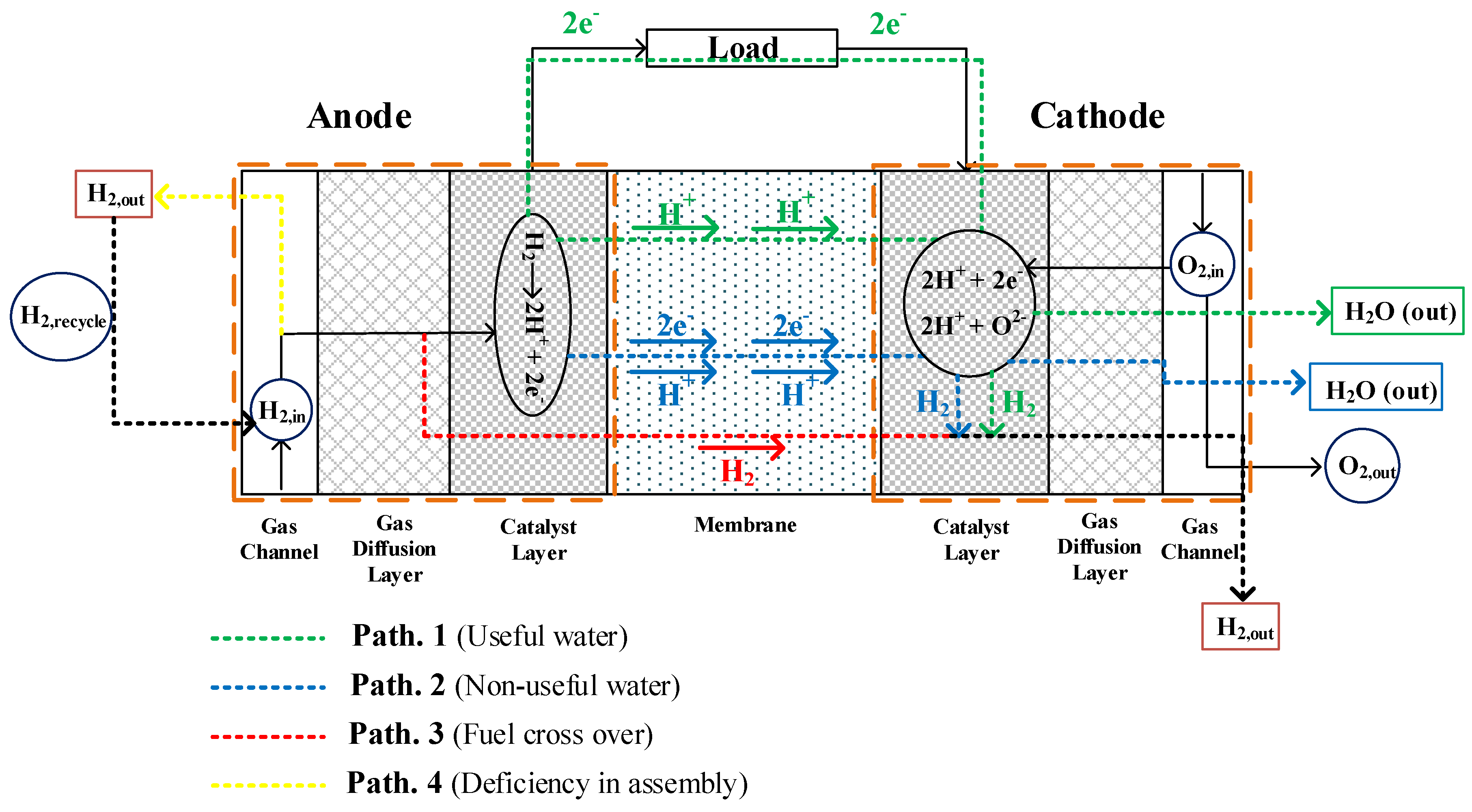
According to the studies carried out in the field of the fuel utilization [18,19,20], it turns out that there is a significant difference between the theoretical and experimental values reported in the literature, which indicates a weakness in the formulation. This weakness in the formulation and the unreasonable intervals for calculating the fuel utilization is notable in the various formulations presented in previous studies. Therefore, different paths for hydrogen consumption in the fuel cell need to be carefully considered. In Figure 2, the different paths for hydrogen flow in a PEMFC are proposed.
According to the diagram presented in Figure 2, the input hydrogen to the fuel cell’s anode may pass through four different paths:
  • Path No. 1: The input hydrogen in the catalyst layer is converted into H+ and electron. Hydrogen ions pass through the membrane and the electrons move through the external circuit to the cathode, generating current. In this path, the hydrogen ion also passes through the membrane on the other side (“Cathode”) and then can react either with the free electrons and re-generate hydrogen, or react with the oxygen ion due to the shown reduction reaction in the cathode side and generate water. The water generated in this state is called “useful water”.
  • Path No. 2: In this path, the input hydrogen in the catalytic layer is converted into H+ ions and electrons, but the electrons produced along with the hydrogen ions pass through the membrane. In this state, electrons pass through the membrane using the momentum drag. That means the movement of hydrogen ions causes dragging of electrons. Hydrogen ions and electrons react in the cathode side after passing through the membrane and re-generate hydrogen. Although it may be possible that the hydrogen ion passing through the membrane reacts with the oxygen ion due to a reduction reaction in the cathode side and generates liquid water, this will be “non-useful water” since the generation of this water is not accompanied by the production of an electric current. In this state, part of the hydrogen is consumed and generates water, but it is not useful. It is obvious that most of the produced electrons in the catalytic layer move through the external circuit to the cathode, which results in the production of external current. However, a small number of electrons produced in the catalytic layer travel through the membrane to the cathode due to the polarity created. To further clarify “Path No. 2”, it can be said that the faradic efficiency of a PEMFC is not completely 100% for two reasons:
    (i)
    The short circuit current, which can arise because of the electrons transfer across the membrane. Such a current is negligible in normal operating conditions despite the membrane can be assumed as a dielectric. This last contribution can be very important as a consequence either of the membrane ageing or the same manufacturing flaws. In the worst case, such a conduction can also arise from the local contact between the two electrodes;
    (ii)
    The gas crossover across the membrane, which in this case can be associated with “Path No. 3”.
  • Path No. 3: Hydrogen passes through the membrane without participating in the oxidation reaction, which is called fuel crossover. Hydrogen passing through the membrane leaves the cathode side of the fuel cell. The amount of hydrogen in this path is negligible, even at high temperatures and high currents.
  • Path No. 4: In this path, the reason for not having an effective hydrogen passage is due to either the lack of proper design of the flow channels or the failure to assemble the components of the fuel cell correctly. This will cause the hydrogen to move out of the output channel in the anode side without having a chance to participate in the oxidation reaction.
Figure 2 illustrated that part of the input hydrogen to the fuel cell is exited from the cathode side (Paths 1–3), and only in Path 4 does unused hydrogen pass through the anode side’s channel. Moreover, even though there are two paths where ionized hydrogen passes through the membrane and liquid water is generated (Path 1 and 2), only in path No. 1 is the water generated a measure of the production of the electric current in the fuel cell. If the value of the fuel utilization is calculated in accordance with Equation (1), it will certainly be a different value from the theoretical factor. In order to modify the fuel utilization formulation based on the results of the diagram presented in Figure 2, a new coefficient was determined as follows:
δ = H 2 O out   with   charge   transfer   H 2 O out   with   charge   transfer + H 2 O out   without   charge   transfer    
By the multiplication of the parameter δ in the main relationship of U F (Equation (1)) more accurate results can be obtained by using the following equation,
U F ,   m o d i f i e d = H 2   in H 2   out H 2   in × δ
Therefore, it can be concluded that one of the most important and influential factors for determining the exact amount of the fuel utilization factor is the amount of liquid water on the cathode side. Hence, it has been proposed to experimentally analyze the effect of the relative humidity of the cathode side on the produced power density following the modified fuel utilization factor.

3. Experimental Measurement

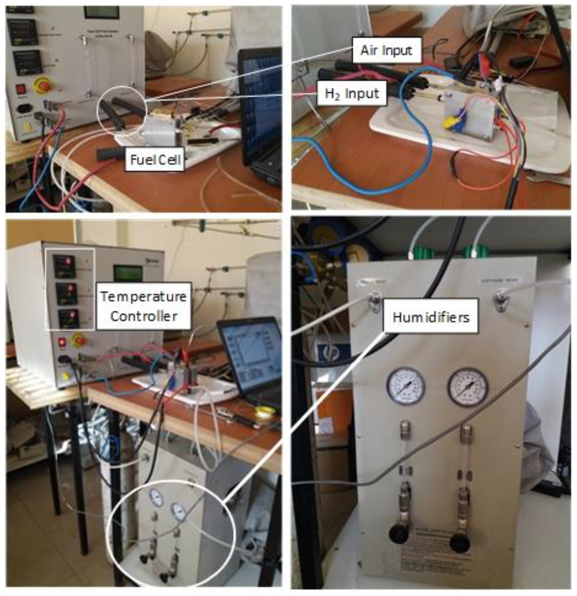
In this research, a FCTS-125W fuel-cell testing machine manufactured by the Asian Hydrogen New Science Company, located in Isfahan, Iran was used to carry out the experiments. An overview of the FCTS-125W test pilot system is presented in Figure 3.
The characteristics of the tested PEMFC and the operating conditions are listed in Table 1. It should be noted that in this paper, as the study has been performed on fuel utilization and fuel cell performance, the amount of reactive gases is considered as additional (with the same value mentioned in Table 1) to prevent the undesirable activity of a limiting factor on performance. However, in studies focusing on flow gas channels and gas diffuser layer, it is necessary to observe stoichiometric ratios to properly analyze the effect of these two parts on the performance of the fuel cell, since these two parts of the fuel cell affect the rate of transfer of reactive gases to the reaction sites (catalytic layer).

4. Results and Discussion

4.1. The Effect of Cathode Relative Humidity on PEMFC Power Density

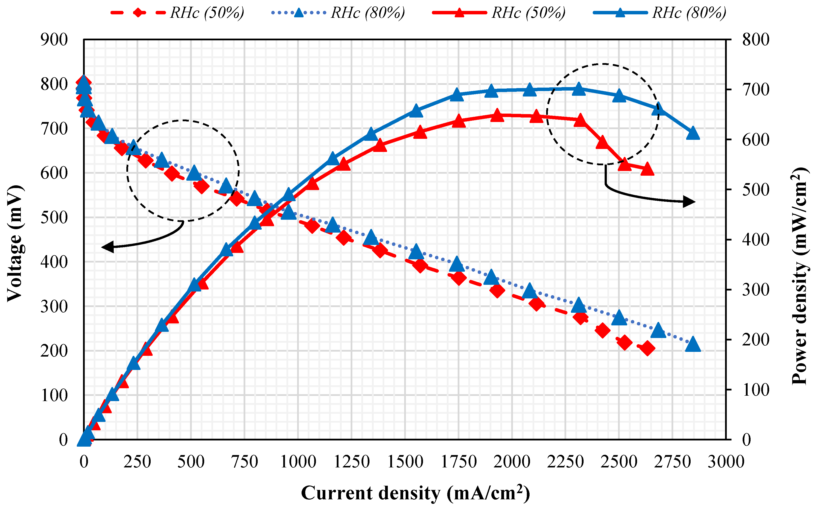
Regarding the water production on the cathode side, the main issue of the relative humidity is its value on the cathode side. In this research, the relative humidity of the cathode side is considered 50% and 80%. The relative humidity of the anode side is always set to be 100%. In Figure 4, performance curves are presented for comparison between 50% and 80% relative humidity in the cathode side.
According to Figure 4, the open circuit voltage (OCV) value for the tested fuel cell is about 0.8 V, which is less than the theoretical value (about 0.9 V). However, the produced current density is relatively high, which causes the final power density to be reasonable. In other words, the difference in the relative humidity of the cathode side has no significant effect on the OCV value, and only increases the range of fuel-cell performance in terms of produced current density. In terms of quantitative comparison, in cathode relative humidity of 50%, the maximum power density is approximately 645 mW/cm2, which is achieved at 2000 mA/cm2 current density. On the other hand, when the relative humidity of the cathode side is equal to 80%, the maximum power density is approximately 700 mW/cm2, which is achieved at 2310 mA/cm2 current density. This shows an increase of 8.5%, compared with the 50% relative humidity of the cathode side at the maximum power density.
The results displayed in Figure 4 can be analyzed in three current ranges:
  • At a current density lower than 500 mA/cm2, increasing the relative humidity of the cathode side does not affect the polarization curve. In fact, in this current density range, the effective factor showing the catalytic effectiveness is the activation losses. The relative humidity change has no effect on the activation losses.
  • At current density values between 500 and 1750 mA/cm2, an increase in relative humidity leads to a gradual increase in the fuel-cell performance curve. Considering the range of medium current densities, the most important losses are the ohmic losses; therefore, increasing the relative humidity of the cathode side causes the membrane to hydrate and the ohmic losses to decrease.
  • At current densities larger than 1750 mA/cm2, the difference between the two performance curves is relatively constant up to a current density of about 2200 mA/cm2 for 50% and 80% relative humidity. On the other hand, at current densities larger than 2200 mA/cm2, the performance curve with a relative humidity of 50% shows a sudden decrease not seen for 80% relative humidity. As the current density depends on the concentration of the reactants at the catalyst layer, it can be concluded that in high current density, the most important voltage loss is due to concentration losses; the main cause of it is the high reaction rate inside the fuel cell and the exothermic nature of the half-reaction of the cathode side. Therefore, increasing the relative humidity can lead to enhancement of the cell’s performance through the further transfer of water into the cell and pushing the membrane to the full hydrated state, despite the increase in the reaction rate inside the fuel cell. It should be noted that excessive moisture might result in a flooding condition in the cathode.
In summary, increasing the relative humidity of the cathode side will increase the output power density of the fuel cell. On the other hand, due to the fact that the fuel cell is a power generation system and converts the fuel’s chemical energy into electrical energy through an electrochemical reaction, it is also necessary to consider the effect of changing relative humidity of the cathode side from the fuel consumption point of view. For this purpose, the modified fuel utilization factor is calculated based on the scenario presented in Figure 2, which is discussed in the next section.

4.2. Calculation of the Modified Fuel Utilization Factor by Using the Parameter δ

In order to calculate the modified fuel utilization factor in accordance with Equation (6), initially, it is necessary to measure the flow rate of both consumable hydrogen and input hydrogen to the fuel cell. According to Faraday’s law, the relationship between the consumed hydrogen and the produced current is as follows [21]:
I = N H 2 · n · F
where, I is produced current in A, N H 2 is the amount of consumable hydrogen in mol/s and n · F is the transferred flux in C/mol. Furthermore, the amount of the inlet flow rate of the hydrogen is calculated in terms of mol/s (Table 1) by using the input fuel density, which is a function of the temperature and pressure of the input flow.
Moreover, parameter δ is calculated according to its definition in the form of Equation (5). To determine the practical value of parameter δ with the appropriate justification, the denominator of Equation (5) is calculated as the sum of the input water to the fuel cell, which is due to the moisture content and the water generated by the electrical current produced. The reason for this is the impossibility of direct measuring of the non-useful water applied in the denominator of Equation (5), as well as performing the measuring under the stable condition of the fuel cell performance.
Under stable conditions, the amount of moisture entering the fuel cell acts as the regulator of the amount of water absorbed by the swollen membrane and the amount of the input fuel’s flow rate to the fuel cell. By determining the consumed hydrogen, the input hydrogen and the parameter δ, the modified fuel utilization factor can be calculated in terms of the produced current. In Figure 5, the results of calculations for the numerical value of the parameter δ and the modified fuel utilization at the 50% and 80% relative humidity of the cathode side are shown. To cover the comparison, the experimental data of other studies have been used for this issue at the 35% relative humidity of the cathode side [22].
As shown in Figure 5, the parameter δ increases with increasing produced current density, which appears quite logical. This incremental ratio is more intense at lower current densities and the variation of the parameter δ decreases with increasing produced current density. Also, it was found that the maximum value achieved for the parameter δ at 50% relative humidity is approximately 0.88, while in the case of 80% relative humidity, the maximum obtained value is approximately 0.72. On the other hand, the modified fuel utilization factor at the 50% relative humidity is higher than that at 80% relative humidity in the cathode side. Furthermore, as shown in Figure 5, at a relative humidity of 35% compared to 50% and 80%, the higher fuel utilization is obtained, which is again aligned with the idea presented in this study. This result is the outcome of the new approach considered in Figure 2 for the consumption of hydrogen and because of the calculation of the modified fuel utilization factor based on the water generated by produced current.
Another important point is that in Figure 5, the value of the parameter δ at the 50% relative humidity is equal to 0.7 at 900 mA/cm2 current density. While at 80% relative humidity, when the produced current density attains about 2500 mA/cm2, the value of the parameter δ is still equal to 0.7. This means that despite the relative humidity of the cathode side being able to increase both produced current density and power generation of the fuel cell, at the same time, as shown in Figure 5, the modified fuel utilization factor which is under the direct effect of the parameter δ is reduced. Therefore, it should be noted that it is necessary to find an optimal range for the relative humidity of the cathode side to achieve the best performance of the fuel cell in terms of power generation and fuel consumption. Hence, increasing the relative humidity of the cathode side itself cannot provide the best result.

5. Conclusions

In this work, which contains both theoretical and experimental analysis, a PEMFC was studied in terms of the fuel utilization factor. In the theoretical part, a new scenario was presented providing a detailed discussion of the various paths that hydrogen can go through in a PEMFC and how it is consumed. The main reason for this theoretical discussion is the existence of an irrational interval in the various formulations presented in the literature to calculate the fuel utilization factor, which indicates a weakness in the formulation. Two modes for the water production were considered in the analysis: “useful water” and “non-useful water”. The term of “usefulness” refers to the state that consumed hydrogen leads to the production of an external electrical current. Considering the fuel utilization factor is directly related to the hydrogen consumption, a correction coefficient (δ) was presented to calculate the theoretical fuel utilization factor, taking into account the two concepts of “useful water” and “non-useful water”. That is the innovation of the theoretical part of this study leading to the calculation of the modified fuel utilization factor. According to the result of the theoretical discussion, one of the effective factors to determine the proper concluded value of the fuel utilization is the amount of liquid water generated on the cathode side, which contains the sum of useful and non-useful water.
An increase in relative humidity to 80% improved the fuel cell performance curve. At a relative humidity of 50% in the cathode side, the maximum power density is approximately 645 mW/cm2, which is achieved at 2000 mA/cm2 current density. At 80% relative humidity, the maximum power density is about 700 mW/cm2, which results in 2310 mA/cm2 current density and shows an increase of about 8.5% with respect to the maximum power density at 50% relative humidity.
An important factor to calculate the exact amount of the fuel utilization is the amount of liquid water at the cathode side. This is considered in the novel introduced parameter δ that was obtained by dividing the useful water to the sum of the useful and non-useful water. The parameter δ increases as the produced current density increases, but this incremental ratio is more intense at the lower current densities. With increasing the produced current density, the variation in the parameter δ decreases and approaches a certain amount of limit. The application of the parameter δ at a 50% and 80% relative humidity in the cathode side causes the modified fuel utilization factor at 50% relative humidity be higher than that at 80%. This conclusion is not aligned with the result achieved in the study of the effect of the relative humidity in the cathode side on the fuel consumption. Therefore, it should be noted that it is necessary to find an optimal range for the relative humidity in the cathode side to achieve the best performance of the fuel cell in terms of power generation and fuel consumption since increasing the relative humidity of the cathode side itself cannot ensure the best result.

Author Contributions

Conceptualization, M.B.Y., H.G. and K.D.; Data curation, M.B.Y., H.G. and N.A.; Formal analysis, H.G., K.D. and B.C.R.T.; Investigation, M.B.Y., H.G., K.D., N.A. and B.C.R.T.; Methodology, M.B.Y., H.G., K.D. and N.A.; Resources, H.G.; Supervision, H.G. and B.C.R.T.; Validation, M.B.Y. and K.D.; Writing—original draft, M.B.Y.; Writing—review & editing, M.B.Y., H.G., K.D., N.A. and B.C.R.T. All authors have read and agreed to the published version of the manuscript.

Funding

This research received no external funding.

Conflicts of Interest

The authors declare no conflict of interest.

Nomenclature

eElectron
FFaraday constant (96,487 C·mol−1)
GDLGas Diffusion Layer
H2Hydrogen
H2OWater
H+Hydrogen ion
ICurrent (A)
nNumber of electrons in the electrochemical reaction
N H 2 Amount of consumable hydrogen (mol·s−1)
O2Oxygen
OCVOpen circuit voltage (V)
PEMFCProton Exchange Membrane Fuel Cell
RHRelative humidity (%)
UFFuel utilization
U F ,   m o d i f i e d Modified fuel utilization
Greek Letters
δ Correction factor for fuel utilization
Superscripts
aanode
ccathode
conconsumed
ininlet
outoutlet

References

  1. Ghadamian, H.; Saboohi, Y. Quantitative analysis of irreversibilities causes voltage drop in fuel cell (simulation & modeling). Electrochim. Acta 2004, 50, 699–704. [Google Scholar]
  2. Ghadamian, H.; Bakhtary, K.; Namini, S.S. An algorithm for optimum design and macro-model development in PEMFC with exergy and cost considerations. J. Power Sources 2006, 163, 87–92. [Google Scholar] [CrossRef]
  3. Kazeminasab, B.; Rowshanzamir, S.; Ghadamian, H. Multi-objective multivariable optimization of agglomerated cathode catalyst layer of a proton exchange membrane fuel cell. Bulg. Chem. Commun. 2015, 47, 38–48. [Google Scholar]
  4. Kim, H.Y.; Kim, K. Numerical study on the effects of gas humidity on proton-exchange membrane fuel cell performance. Int. J. Hydrogen Energy 2016, 41, 11776–11783. [Google Scholar] [CrossRef]
  5. Ozen, D.N.; Timurkutluk, B.; Altinisik, K. Effects of operation temperature and reactant gas humidity levels on performance of PEM fuel cells. Renew. Sustain. Energy Rev. 2016, 59, 1298–1306. [Google Scholar] [CrossRef]
  6. Kazeminasab, B.; Rowshanzamir, S.; Ghadamian, H. Nitrogen doped graphene/cobalt-based catalyst layers of a PEM fuel cell: Performance evaluation and multi-objective optimization. Korean J. Chem. Eng. 2017, 34, 2978–2983. [Google Scholar] [CrossRef]
  7. Ou, K.; Yuan, W.W.; Choi, M.; Yang, S.; Kim, Y.B. Performance increase for an open-cathode PEM fuel cell with humidity and temperature control. Int. J. Hydrog. Energy 2017, 42, 29852–29862. [Google Scholar] [CrossRef]
  8. Muirhead, D.; Banerjee, R.; George, M.G.; Ge, N.; Shrestha, P.; Liu, H.; Lee, J.; Bazylak, A. Liquid water saturation and oxygen transport resistance in polymer electrolyte membrane fuel cell gas diffusion layers. Electrochim. Acta 2018, 274, 250–265. [Google Scholar] [CrossRef] [Green Version]
  9. Hasheminasab, M.; Kermani, M.J.; Nourazar, S.S.; Khodsiani, M.H. A novel experimental based statistical study for water management in proton exchange membrane fuel cells. Appl. Energy 2020, 264, 114713. [Google Scholar] [CrossRef]
  10. Wang, B.; Wu, K.; Xi, F.; Xuan, J.; Xie, X.; Wang, X.; Jiao, K. Numerical analysis of operating conditions effects on PEMFC with anode recirculation. Energy 2019, 173, 844–856. [Google Scholar] [CrossRef]
  11. Rahman, M.A.; Mojica, F.; Sarker, M. Abel Chuang, P.Y. Development of 1-D multiphysics PEMFC model with dry limiting current experimental validation. Electrochim. Acta 2019, 320, 134601. [Google Scholar] [CrossRef]
  12. Jeon, D.H.; Kim, K.N.; Baek, S.M.; Nam, J.H. The effect of relative humidity of the cathode on the performance and the uniformity of PEM fuel cells. Int. J. Hydrog. Energy 2011, 36, 12499–12511. [Google Scholar] [CrossRef]
  13. Abdollahzadeha, M.; Pascoa, J.C.; Ranjbar, A.A.; Esmaili, Q. Analysis of PEM (Polymer Electrolyte Membrane) fuel cell cathode two-dimensional modeling. Energy 2014, 68, 478–494. [Google Scholar] [CrossRef]
  14. Nishikawa, H.; Sasou, H.; Kurihara, R.; Nakamura, S.; Kano, A.; Tanaka, K.; Aoki, T.; Ogami, Y. High fuel utilization operation of pure hydrogen fuel cells. Int. J. Hydrog. Energy 2008, 33, 6262–6269. [Google Scholar] [CrossRef]
  15. Iranzo, A.; Boillat, P.; Biesdorf, J.; Salva, A. Investigation of the liquid water distributions in a 50 cm2 PEM fuel cell: Effects of reactants relative humidity, current density, and cathode stoichiometry. Energy 2015, 82, 914–921. [Google Scholar] [CrossRef]
  16. Muirhead, D.; Banerjee, R.; Lee, J.; George, M.G.; Ge, N.; Liu, H.; Chevalier, S.; Hinebaugh, J.; Han, K.; Bazylak, A. Simultaneous characterization of oxygen transport resistance and spatially resolved liquid water saturation at high-current density of polymer electrolyte membrane fuel cells with varied cathode relative humidity. Int. J. Hydrog. Energy 2017, 42, 29472–29483. [Google Scholar] [CrossRef]
  17. Yousefkhani, M.B.; Ghadamian, H.; Massoudi, A.; Aminy, M. Quantitative and qualitative investigation of the fuel utilization and introducing a novel calculation idea based on transfer phenomena in a polymer electrolyte membrane (PEM) fuel cell. Energy Convers. Manag. 2017, 131, 90–98. [Google Scholar] [CrossRef]
  18. Farhat, Z.N. Modeling of catalyst layer microstructural refinement and catalyst utilization in a PEM fuel cell. J. Power Sources 2004, 138, 68–78. [Google Scholar] [CrossRef]
  19. Hwang, J.W.; Lee, J.Y.; Jo, D.H.; Jung, H.W.; Kim, S.H. Polarization characteristics and fuel utilization in anode-supported solid oxide fuel cell using three-dimensional simulation. Korean J. Chem. Eng. 2011, 28, 143–148. [Google Scholar] [CrossRef]
  20. Han, I.; Jeong, J.; Shin, H.K. PEM fuel-cell stack design for improved fuel utilization. Int. J. Hydrog. Energy 2013, 38, 11996–12006. [Google Scholar] [CrossRef]
  21. Barbir, F. PEM Fuel Cells: Theory and Practice; University of Connecticut: Storrs, CT, USA; Elsevier: San Diego, CA, USA, 2005; pp. 33–34. [Google Scholar]
  22. Arif, M.; Cheung, S.C.P.; Andrews, J. A systematic approach for matching simulated and experimental polarization curves for a PEM fuel cell. Int. J. Hydrogen Energy 2019, 45, 2206–2223. [Google Scholar] [CrossRef]
Figure 1. Schematic of a polymer electrolyte membrane fuel cell (PEMFC) showing the electrochemical reactions and the current production.
Energies 13 06117 g001
Figure 2. Different scenario for hydrogen flow paths in a PEMFC.
Energies 13 06117 g002
Figure 3. An overview of the FCTS-125W test pilot system.
Energies 13 06117 g003
Figure 4. The effect of increasing the relative humidity of the cathode side on the performance curve.
Energies 13 06117 g004
Figure 5. δ and the modified fuel utilization in terms of the total produced current density, at 35%, 50% and 80% relative humidity of the cathode side.
Energies 13 06117 g005
Table 1. Technical and physical characteristics of the tested PEMFC and operating conditions.
CharacteristicDescription/Value
Cell parameters
Flow channel typeSingle serpentine
Flow collectors materialStainless steel
End plate materialAluminum alloy
Maximum operating temperature (°C)90
Maximum operating pressure (bar)2
Active surface area (cm2)5
Operating conditions
Anode pressure (bar)1
Cathode pressure (bar)1
Inlet flow rate of H2 (lit/min)0.3
Inlet flow rate of O2 (lit/min)0.3
Cell Temperature (°C)60
Anode Temperature (°C)60
Cathode Temperature (°C)56
Anode relative humidity (%)100
Publisher’s Note: MDPI stays neutral with regard to jurisdictional claims in published maps and institutional affiliations.