Article

Load Frequency Control of Photovoltaic Generation-Integrated Multi-Area Interconnected Power Systems Based on Double Equivalent-Input-Disturbance Controllers

1
School of Automation, Central South University, Changsha 410083, China
2
Hunan Xiangjiang Artificial Intelligence Academy, Changsha 410083, China
3
Department of Civil, Environment & Geomatic Engineering, University College London, London WC1E 6BT, UK
*
Author to whom correspondence should be addressed.
Energies 2020, 13(22), 6103; https://doi.org/10.3390/en13226103
Submission received: 22 October 2020 / Revised: 16 November 2020 / Accepted: 19 November 2020 / Published: 21 November 2020
(This article belongs to the Section F: Electrical Engineering)

Abstract

:
With the rapid increase of photovoltaic (PV) penetration and distributed grid access, photovoltaic generation (PVG)-integrated multi-area power systems may be disturbed by more uncertain factors, such as PVG, grid-tie inverter parameters, and resonance. These uncertain factors will exacerbate the frequency fluctuations of PVG integrated multi-area interconnected power systems. For such system, this paper proposes a load frequency control (LFC) strategy based on double equivalent-input-disturbance (EID) controllers. The PVG linear model and the multi-area interconnected power system linear model were established, respectively, and the disturbances were caused by grid voltage fluctuations in PVG subsystem and PV output power fluctuation and load change in multi-area interconnected power system. In PVG subsystems and multi-area interconnected power systems, two EID controllers add differently estimated equivalent system disturbances, which has the same effect as the actual disturbance, to the input channel to compensate for the impact of actual disturbances. The simulation results in MATLAB/Simulink show that the frequency deviation range of the proposed double EID method is 6% of FA-PI method and 7% of conventional PI method, respectively, when the grid voltage fluctuation and load disturbance exist. The double EID method can better compensate for the effects of external disturbances, suppress frequency fluctuations, and make the system more stable.

1. Introduction

With the rapid development of economy and society, people’s demand for electricity is increasing day by day. In order to meet the needs of production and life, regional grids have become increasingly interdependent and interactive and the power quality of power supply and distribution systems has become increasingly important. A large-scale interconnected power system consists of many interconnected subsystems (so called control areas), which are connected to each other by tie lines. Each area has its own generator or generator sets to meet its own load demand and power interchange needs with neighbours [1]. If the power of an area fluctuates due to load fluctuations, communication link delays and failures, the frequency stability of the entire system will be destroyed. In order to effectively control the stability of the grid frequency and thus improve power quality, load frequency control (LFC) systems are widely used in interconnected power grids to make the deviation of the system close to zero, including area control error (ACE), frequency deviation, and tie line power deviation.
In recent years, due to abundant solar energy resources and no environmental pollution issues, distributed power generation technology based on solar energy has developed rapidly around the world. photovoltaic generation (PVG) is widely used in multi-area interconnection power systems. However, the solar-based distributed generation system has poor controllability and is easily affected by changes in the external environment (e.g., voltage and weather), which makes it difficult for PVG systems to output stable power. Moreover, as the permeability of PVG increases, it occupies part of the space of conventional generators and reduces the reserve capacity of the grid’s primary frequency modulation resources [2,3]. It reduces the frequency modulation capability of the grid. At the same time, due to the lack of synchronous torque, the increased penetration of PVG will continue to lead to the reduction of system inertia, which will also affect the frequency regulation capacity [4,5,6,7,8]. Therefore, it is necessary to solve the problem of LFC of PVG integrated multi-area interconnected power systems.
Domestic and foreign scholars have carried out relevant research on the LFC of PVG integrated power systems. Abd-Elazim and Ali [9] proposed a firefly algorithm to optimize the PI (FA-PI) controller and optimize the LFC strategy of a hybrid system composed of PV subsystems and thermal generators. Sa-ngawong and Ngamroo [10] have proposed a Sugeno fuzzy logic controller for intelligent PV power plants based on particle swarm optimization algorithm to suppress frequency fluctuations in multi-area interconnected power systems. In order to reduce the frequency deviation caused by mismatched parameters such as PV and different load disturbances, Yang et al. [11] proposed a sliding mode load frequency controller based on disturbance observer. Different from the above research, by considering the nonlinear characteristics of the governor’s dead zone and the turbine’s power generation rate constraints, Zeng et al. [12] proposed an adaptive model predictive LFC method for a PVG integrated multi-area interconnected power system.
The LFC methods involved in the above studies include: PI/PID control [13,14,15,16,17,18], fuzzy control [19,20,21,22,23,24], sliding mode control [25,26,27,28,29,30], and model predictive control [31,32,33,34,35,36]. Although conventional PI/PID control, which is not combined with other algorithms, is widely used in LFC because of its simple structure, it cannot adjust parameters in real time. As a result, the system cannot response to different disturbances with good dynamic performance. Once it is combined with other algorithms to adjust the parameters in real time, its structure will be complicated. The advantage of fuzzy control is that it does not require an accurate mathematical model and is robust, but its design lacks generality and highly rely on experience. Although sliding mode control can overcome the uncertainty of the system and is robust to disturbances and unmodeled dynamics, it has a serious drawback: jitter, and the larger switching range of the control variable, the more significant the jitter. MPC uses rolling optimization strategy to compensate for the impact of uncertainty on frequency in a timely manner. However, due to the large amount of online computing, it requests a high-performance computer environment. Overall, these methods are either computationally intensive or have complex algorithm structures, and are not suitable for controlling complex PVG integrated multi-area interconnected power systems.
In fact, the LFC problems is mainly concentrated on small load disturbances. Given this, the LFC problem of PVG integrated multi-area interconnected power systems is regarded as a disturbance rejection problem. The equivalent-input-disturbance (EID) method is a very effective method for disturbance suppression. The core of the EID method is to introduce the reverse estimated equivalent external disturbance into the input channel to compensate for the actual disturbance. The EID method with a simple structure can simultaneously suppress multiple arbitrary external disturbances with equivalent disturbances. The EID method has low computation cost because the control parameters of the feedback controller, state observer, and low-pass filter in the control system can be designed independently. EID has been successfully applied in vehicle steering control [37] and power system with wind farms [38] and has shown excellent disturbance rejection performance.
For PVG-integrated multi-area interconnected power systems with grid voltage fluctuations and load fluctuations, this paper proposes a double EID strategy to control the frequency stability of the system. One of the EID controllers was used in PVG subsystems to maintain stable output power by suppressing grid voltage fluctuations and controlling the output current of the inverter. Another EID controller was used in interconnected power systems to maintain system power balance and frequency stability by suppressing PV output power fluctuations and load disturbances. This strategy generates a new control signal by estimating equivalent disturbance and compensates for the effect of actual disturbance. It has a simple structure and does not require prior information about disturbance. To the best of the authors’ knowledge, this work can be considered as the first contribution of EID to the optimal LFC issue of a PVG integrated multi-area interconnected power system. Double EID LFC strategy can suppress the power grid voltage fluctuation and load demand disturbance and ensures that PVG integrated multi-area interconnected power systems operate normally.

2. System Description and Modeling

Section 2 describes the entire system and establishes a linearized model of PVG and a linearized model of LFC for the entire PVG integrated multi-area interconnected power systems.

2.1. Description of PVG Integrated Multi-Area Interconnected Power System

PVG integrated multi-area interconnected power systems usually consist of several control areas through tie lines. For simplicity, we consider a PVG integrated two-area interconnected power system, including traditional power generation subsystems, PVG subsystems, energy storage (ES) subsystems, and double EID controllers (red box). The PVG integrated two-area interconnected power system is shown in Figure 1.

2.2. Modeling of PVG Integrated Multi-Area Interconnected Power System

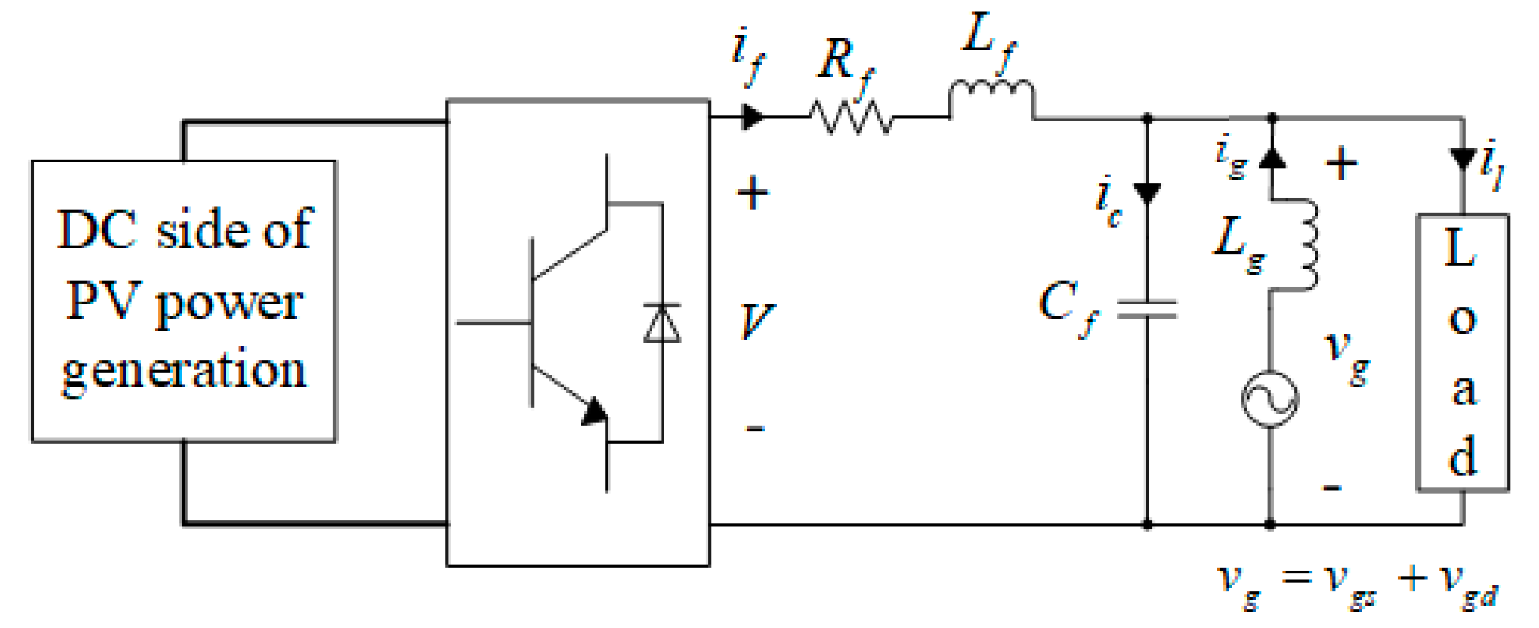
Figure 2 shows a block diagram of the connection between a grid and a PV generator. The DC side of the single-phase PV grid-connected inverter consists of a PV panel, a DC-DC converter, and a maximum power tracking (MPPT) controller. The MPPT is embedded in the DC-DC converter. if and V are the current and voltage of the output side of the inverter respectively. il and ig are load current and grid current, respectively. vg, vgs and vgd are grid voltage, grid reference voltage, and grid voltage fluctuation, respectively. The low-pass filter (LPF) is composed of Rf, Lf and Cf.
According to Figure 2, the following equation can be established:
i ˙ f = R f L f i f + 1 L f V 1 L f v g
where vg = vgs + vgd, so it can be expressed as:
i ˙ f = R f L f i f + 1 L f V 1 L f ( v g s + v g d )
Based on the superposition theorem, vgs can be ignored, and the above formula can be rewritten as the following state space expression:
{ x ˙ p ( t ) = A p x p ( t ) + B p u p ( t ) + B d p d p ( t ) y p ( t ) = C p x p ( t ) + D p u p ( t )
where xp(t) is the state; up(t) is the control input; yp(t) is the output; dp(t) is the disturbance of the PVG subsystem, and xp(t) = if, up = V, dp(t) = vgd, yp(t) = if, Ap = −Rf/Lf, Bp = 1/Lf, Bdp = −1/Lf, Cp = 1, Dp = 0.
Due to the different power equipment connected to the power grid and the different electricity consumption during the day and night, there will be load disturbance in PVG integrated multi-area interconnected power systems. The output of the traditional power generation subsystem can compensate the load disturbance and output power fluctuation of the PVG subsystem. Therefore, it is necessary to establish a linearization model of a PVG integrated multi-area interconnected power system.
In a multi-area power system, in order to accurately evaluate the control effect, in addition to the frequency and the tie line power deviation, the concept of area control error (ACE) needs to be introduced. ACE indicates the degree of mismatch between regional load demand and generated power. The ACE calculation formulas for the area 1 and the area 2 can be expressed as:
{ ACE 1 = β 1 Δ f 1 + Δ P tie ACE 2 = β 2 Δ f 2 Δ P tie
The linear model of LFC for the PVG integrated two-area interconnected power system is:
Δ f ˙ 1 = D 1 M 1 Δ f 1 + 1 M 1 Δ P t 1 + 1 M 1 Δ P b 1 1 M 1 Δ P tie + 1 M 1 ( Δ P p v 1 Δ P l o a d 1 )
Δ P ˙ t 1 = 1 T t 1 Δ P t 1 + 1 T t 1 Δ X g 1
Δ X ˙ g 1 = 1 R 1 T g 1 Δ f 1 1 T g 1 Δ X g 1 + 1 T g 1 Δ P r 1
Δ P ˙ b 1 = K b 1 T b 1 Δ f 1 1 T b 1 Δ P b 1
Δ P ˙ t i e = 2 π T 1 2 Δ f 1 2 π T 1 2 Δ f 2
Δ f ˙ 2 = D 2 M 2 Δ f 2 + 1 M 2 Δ P t 2 + 1 M 2 Δ P b 2 1 M 2 Δ P t i e + 1 M 2 Δ P p v 2 Δ P l o a d 2
Δ P ˙ t 2 = 1 T t 2 Δ P t 2 + 1 T t 2 Δ X g 2
Δ X ˙ g 2 = 1 R 2 T g 2 Δ f 2 1 T g 2 Δ X g 2 + 1 T g 2 Δ P r 2
Δ P ˙ b 2 = K b 2 T b 2 Δ f 2 1 T b 2 Δ P b 2
Combined with Equations (5)–(13), it can be written as the following state space equation:
{ x ˙ s ( t ) = A s x s ( t ) + B s u s ( t ) + B d s d s ( t ) y s ( t ) = C s x s ( t )
where xs(t) is the state; us(t) is the control input; ys(t) is the output; ds(t) is the disturbance of the interconnected power system, and x s = [ Δ f 1 Δ P t 1 Δ X g 1 Δ P b 1 Δ P t i e Δ f 2 Δ P t 1 Δ X g 1 Δ P b 1 ] T , u s = [ Δ P r 1 Δ P r 2 ] T , d s = [ Δ P p v 1 Δ P l o a d 1 Δ P p v 2 Δ P l o a d 2 ] T , y s = [ A C E 1 A C E 2 Δ f 1 Δ f 2 Δ P t i e ] T . If the communication link delay is considered, the delay term needs to be added to Equation (14).

3. Design of Double EID Controllers

Section 3 first introduces the EID method and then analyses the system stability. Finally, a double EID strategy was proposed for the PVG integrated multi-area interconnected power system.

3.1. EID Method

In this study, EID method was used to compensate the voltage fluctuation and load disturbance. The core of EID method is to reversely add an estimated equivalent disturbance on the control input channel that is the same as the effect of the actual disturbance on the output, so as to compensate the effect of the actual disturbance. Assuming Equation (3) is controllable and observable, a system with disturbance on the control input channel can be written as:
{ x ˙ ( t ) = A x ( t ) + B ( u ( t ) + d e ( t ) ) y ( t ) = C x ( t )
Let the control input of Equations (3) and (15) equal to 0. If the disturbance de(t) has the same effect on the system as the real disturbance d(t) has on the system, that is, when t is greater than 0, y(t) is equal to y’(t). Then de(t) is regarded as the equivalent input disturbance of the actual disturbance d(t). The same is true for Equation (14). If the communication link delay is considered, the observability and controllability of the system need to meet [39]:
r a n k [ s I n A A d e h s B ] = n
r a n k [ s I n A A d e h s C ] = n
where n is the number of states and h is the positive time delay, and Ad is the system matrix of delay terms.
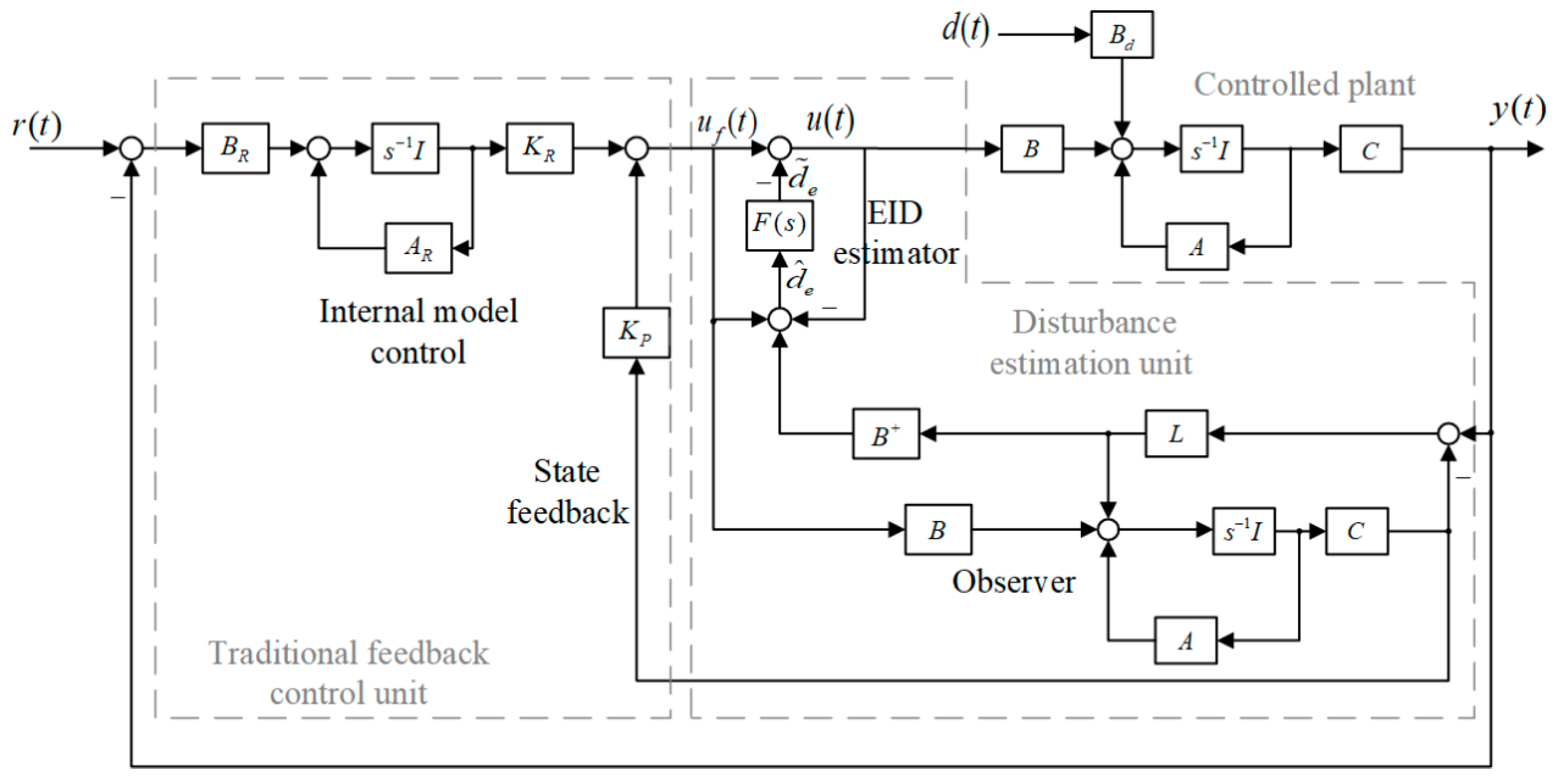
As shown in Figure 3, the EID controller consists of a traditional feedback control unit, a disturbance estimation unit and a controlled plant. The traditional feedback control unit includes an internal model controller and a state feedback controller. The disturbance estimation unit includes a state observer and an EID estimator. The EID controller can be considered as the disturbance compensator. It estimates disturbances by obtaining relevant information about disturbances from the state observer, such as voltage fluctuations, load disturbances. AR and BR are the system matrix and input matrix of the internal model controller, respectively. F(s) is the low-pass filter.
The EID method adds estimate equivalent disturbances to the control inputs to compensate for the effects of actual disturbances. The new control law is:
u ( t ) = u f ( t ) d ˜ e ( t )
The state feedback control law is:
u f ( t ) = K P x ^ ( t ) + K R x R ( t )
where x ^ ( t ) is the observer state, xR(t) is the internal model controller state, and KP and KR are state feedback gains.
The state observer used in this paper is:
{ x ^ ˙ ( t ) = A x ^ ( t ) + B u f ( t ) + L ( y ( t ) y ^ ( t ) ) y ^ ( t ) = C x ^ ( t )
where L is the state observer gain.
Combining Equations (15), (16) and (20), the estimated equivalent input disturbance d ^ e ( t ) can be solved:
d ^ e ( t ) = B + L C [ x ( t ) x ^ ( t ) ] + u f ( t ) u ( t )
where B+ = (BTB)−1BT. In this study, EIDs of the voltage fluctuation and the load disturbance will be added to the control signal to compensate for the effect of the actual disturbance.
Because d ^ e ( t ) contains noise, it needs to be filtered by a low-pass filter. This study chose a low-pass filter [40]:
F ( s ) = 1 T s + 1
where T is the time constant of the filter.
The filtered estimated disturbance is:
D ˜ e ( s ) = F ( s ) D ^ e ( s )
where D ˜ e ( s ) and D ^ e ( s ) are Laplace transforms of d ˜ e ( s ) and d ^ e ( s ) , respectively. In order for the EID to be close to the actual disturbance, it needs to satisfy:
F d ( j ω ) I , ω [ 0 , ω d ]
where wd is the maximum value of the estimated disturbance angular frequency. Generally, the cut-off angular frequency of the filter is from 5 to 10 times wd.

3.2. System Stability

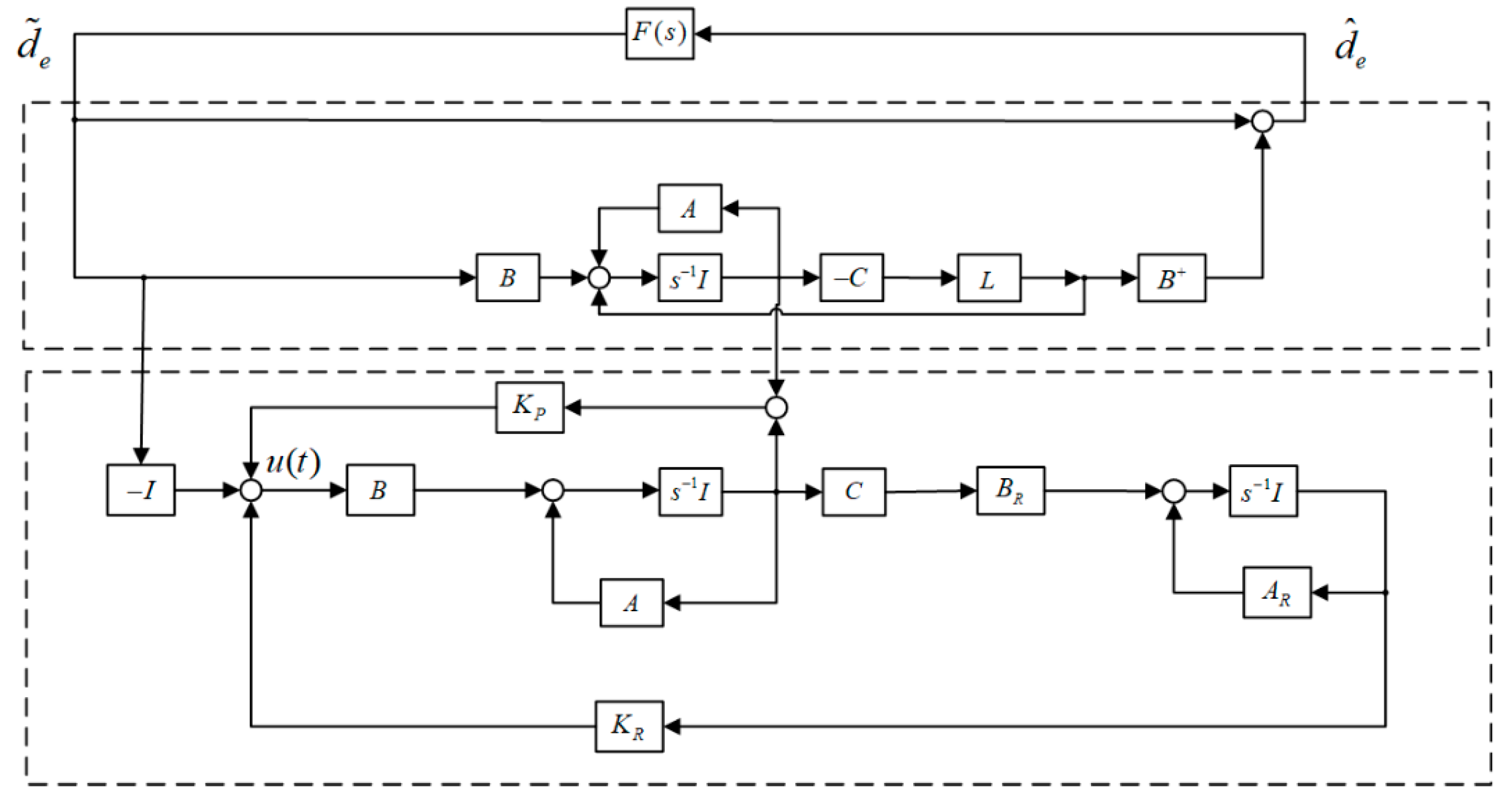
Obviously, when the input is equal to 0, Figure 3 can be converted into Figure 4. In Figure 4, the transfer function of d ˜ e ( s ) to d ^ e ( s ) is [40]:
G d ( s ) = B + ( s I A ) [ s I ( A L C ) ] 1 B
The controller is divided into two parts (dashed box). The separation theorem is applied to this controller, so KP, KR, and L can be designed independently of each other. The upper part of Figure 4 can be simplified into Figure 5.
According to the small gain theorem, Based on the small gain theorem, we can obtain the following stable conditions: For a suitable designed state-feedback gain K = [ K P K R ] , the closed-loop EID-based system under the control law (17) is stable if
G d ( s ) F ( s ) < 1
where G d ( s ) F ( s ) : = sup 0 ω σ max [ G d ( j ω ) F ( j ω ) ] , σ max ( G d ( j ω ) ) is the maximum singular value of Gd (jw). Since the filter is constructed, only the coefficient L needs to be designed to satisfy the Equation (26). If the delay of the communication link is considered, the stability of the system can be obtained by using Lyapunov-Krasovskii function and linear matrix inequality [41,42,43].
In order to obtain KP and KR, the following extended models were selected:
x ¯ ˙ ( t ) = A ¯ x ¯ ( t ) + B ¯ u ¯ ( t )
where x ¯ ( t ) = [ x T ( t ) x R T ( t ) ] T , A ¯ = [ A 0 B R C A R ] , B ¯ = [ B 0 ] . Based on the optimal control theory, minimizing the performance index:
J K = 0 [ x ¯ T ( t ) Q K x ¯ ( t ) + u ¯ T ( t ) R K u ¯ ( t ) ] d t
based on for selected weighting matrices QK > 0, RK > 0 gives K = [ K P K R ] = R K 1 B ¯ T P where P is the solution of the Riccati equation A ¯ T P + P A ¯ + Q K P B ¯ R K B ¯ T P = 0 .
Because KP, KR, and L can be designed independently, we could also choose the performance index to calculate KP and KR, which is different from the performance index of L.
In order to obtain L, the dual system of the plant is considered:
{ x L ( t ) = A T x L ( t ) + C T u L ( t ) y L ( t ) = B T x L ( t )
and the control law is:
u L ( t ) = L x L ( t )
Similarly, L is obtained by minimizing the performance index:
J = 0 [ ρ x L T ( t ) Q L x L ( t ) + u L T ( t ) R L u L ( t ) ] d t
where QL > 0 and RL > 0, By adjusting ρ, L can satisfy Equation (26).

3.3. Double EID Control Strategy

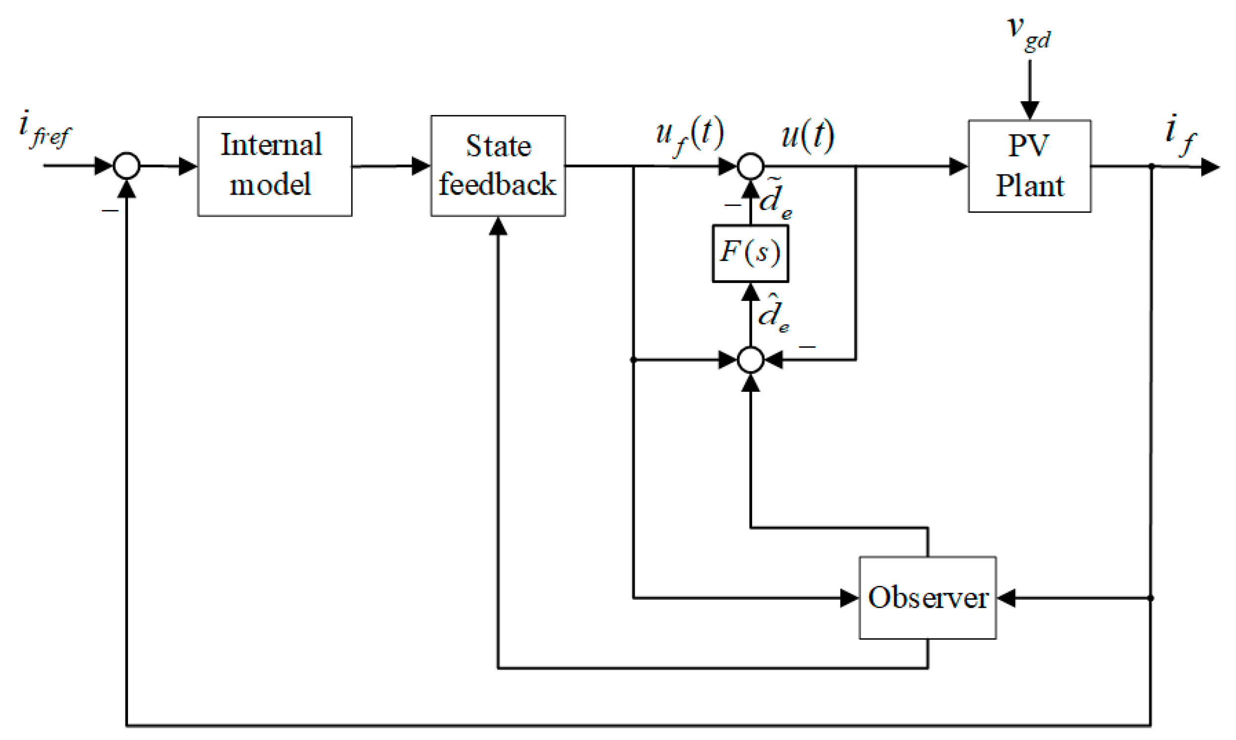
In this study, an LFC strategy based on double EID controllers was proposed for the PVG-integrated multi-area interconnected power systems suffering grid voltage fluctuation and load demand disturbance. One of the EID controllers was used in PVG subsystems. The PVG linear model is shown in Equation (3). As shown in Figure 6, the PVG subsystem based on the EID method regards grid voltage fluctuations vgd as external disturbances. The EID method adds the estimated equivalent disturbance to the control input to compensate the actual disturbance effect. At the same time, the estimated equivalent disturbance participates in the change of the reference current to ensure that the output power of the PVG subsystem remains unchanged. This EID controller tracks the reference current without static errors, so that the output power of the PVG subsystem is stable.
Another EID controller was applied to interconnected power systems to achieve system power balance and keep the frequency within normal range. A linear model of the PVG integrated two-area interconnected power system is shown in Equation (14). The interconnected power system based on EID method regards the fluctuation of the output power of the PVG subsystem and the change of load demand as system disturbance. In the interconnected power system, in addition to ensuring that the frequency of each area is within the normal range, it must also ensure that the ACE and the tie line power deviation are small. This is also a necessary condition for the normal operation of multi-area interconnected power systems and an important evaluation standard for load frequency control.

4. Results and Discussion

The allowable range of the frequency deviation of the power system is ±0.2 Hz, which was used as the standard in this study. Three simulation experiments were carried out for a PVG integrated two-area interconnected power system to verify the effectiveness and applicability of the proposed double EID method under different conditions.
The values of all the coefficients in the PVG integrated two-area interconnected power system are given in Appendix A Table A1. The following first-order low-pass filter was selected:
F ( s ) = 100 s + 101
The state space expression of the filter in the PVG subsystem is:
A F p = 101 , B F p = 100 , C F p = 1
Because the PVG integrated two-area interconnected power system is a multiple-input multiple-output system, the state space expression of the filter is:
A F s = ( 101 0 0 101 ) , B F s = ( 1 0 0 1 ) , C F s = ( 100 0 0 100 )
For the linearization model of the PVG subsystem, by using Equations (28) and (31) and choosing QK = diag (5 109), RK = 1, ρ = 106, QL = 100 and RL = 1, the state feedback gain and the state observer gain could be obtained where Kp = (8.2411 3.1622 × 10⁴), Lp = 3.1423 × 10³.
For the PVG integrated two-area interconnected power system, the state feedback gain and the state observer gain could be obtained by Equations (28) and (31) as well and choosing QK = diag (1011 105 106 107 107 105 104 103 106 103 104 107 109 105), RK = diag (104 111), ρ = 106, QL = diag (50 10−4 10−3 10−4 10−3 10−4 10−2 10−4 10−4) and RL = diag (1 1 1 1 1), where:
K s = ( 3.2644 0.0031 0.0099 0.0034 0.0953 0.0018 0.0000   0.4646 0.0005 0.0001 0.0006 0.3024 1.2573 0.0067   0.0000 0.0000 0.0000 0.0003 0.0016 0.1628 0.0026   0.0068 0.0134 0.0001 0.0015   0.0256 2.5556 0.0147 ) × 10 3 ,
L s = ( 2.7612 0.0051 6.5096 0.0005 0.0054 0.00001 0.0000 0.0000 0.0000 0.0000 0.0004 0.0001 0.0013 0.0001 0.0001 0.0141 0.0037 0.0440 0.0015 0.0046 0.0165 0.0180 0.0054 0.0013 0.0188 0.0011 0.0039 0.0005 0.0086 0.0013 0.0000 0.0002 0.0000 0.0003 0.0000 ) × 10 3 .
Three cases were simulated in MATLAB. First, the fluctuation of the output power of the PVG subsystem was studied in the case of a sudden drop in the grid voltage. Secondly, the step load response of the two-area interconnected power system was investigated and compared under the EID method, the FA-PI control method [9] and the conventional PI control method. Finally, in the case of random fluctuations in grid voltage and load, the control performance of the proposed double EID method, the FA-PI control method [9] and the conventional PI control method were compared.

4.1. Output Power Response of PVG Subsystem with Grid Voltage Sag

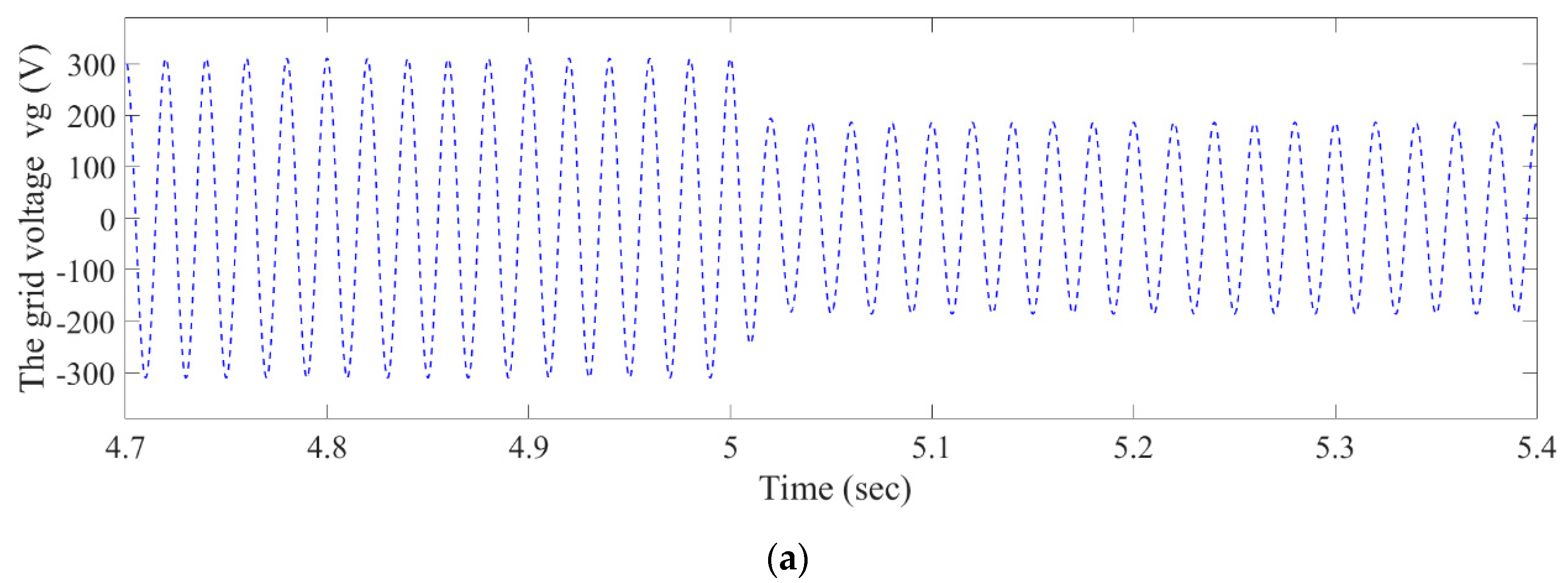
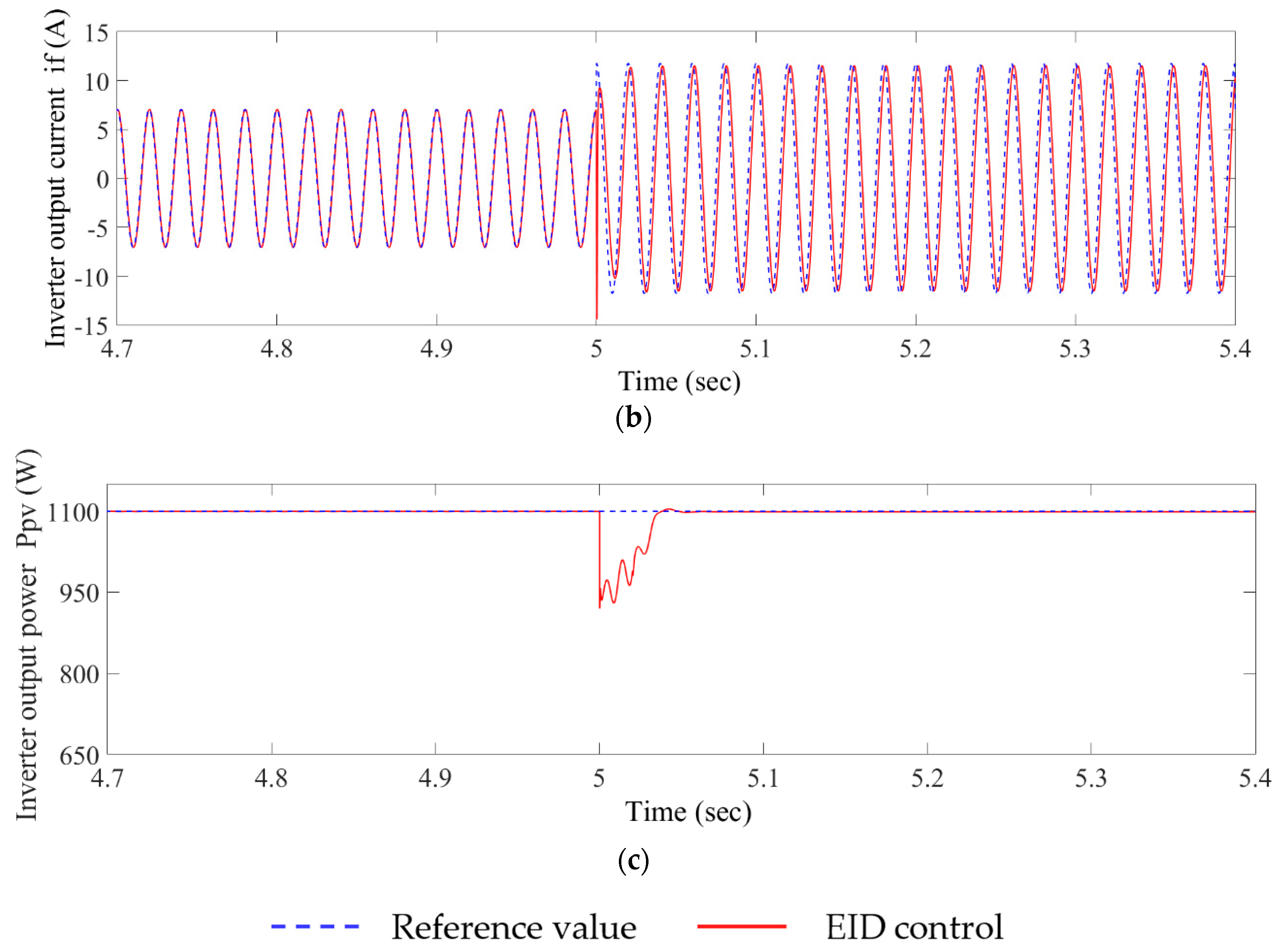
We performed simulation experiments of the PVG subsystem when the grid voltage plummets. The output current and output power of the PVG subsystem are actually the output current and output power of the PV grid-connected single-phase inverter. In the experiment, the reference output active power of the inverter was set to 1100 W, the frequency of the PCC voltage is 50 Hz, the simulation time is 60 s, and only t = 4.7 s~5.4 s simulation date are displayed. The root mean square (RMS) of the point of common coupling (PCC) changed from 220 V to 132 V at the 5th second, and the voltage of PCC decreased by 40%.
In Figure 7b, after half a cycle after the voltage dip, the inverter output current starts to follow the reference current. In the third cycle, the inverter output current can better follow the reference current, and the delay of the output current is small. The output power of the inverter fluctuates the most at 5.001 s, but it converges to 1100 W, which is the reference value, at 5.05 s. This shows that when the grid voltage dips, the controller quickly estimates the disturbance and compensates for the disturbance, which enables the inverter output current to quickly track the reference current and the output power to recover to the rated value in a short time.

4.2. Load Frequency Response of Step Load Disturbances

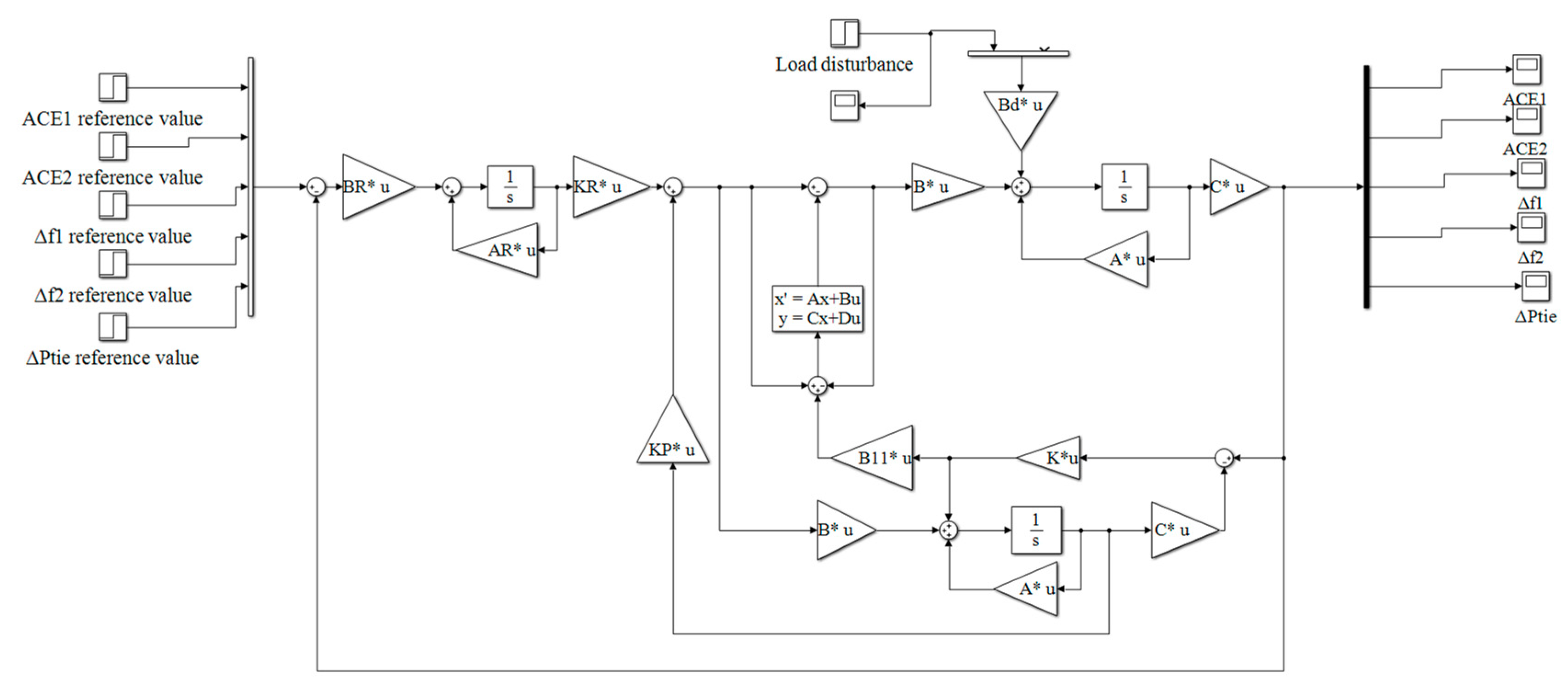
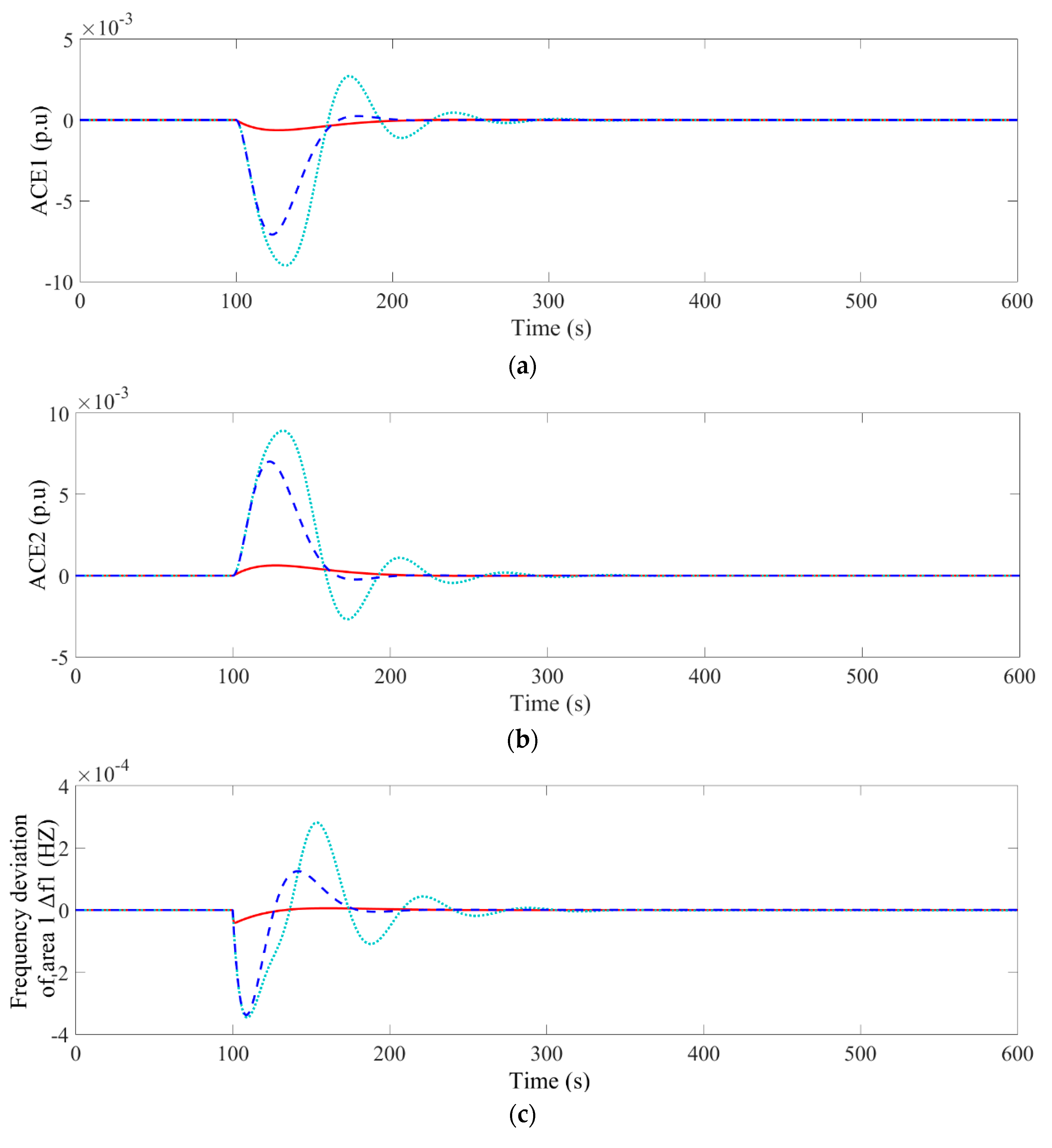
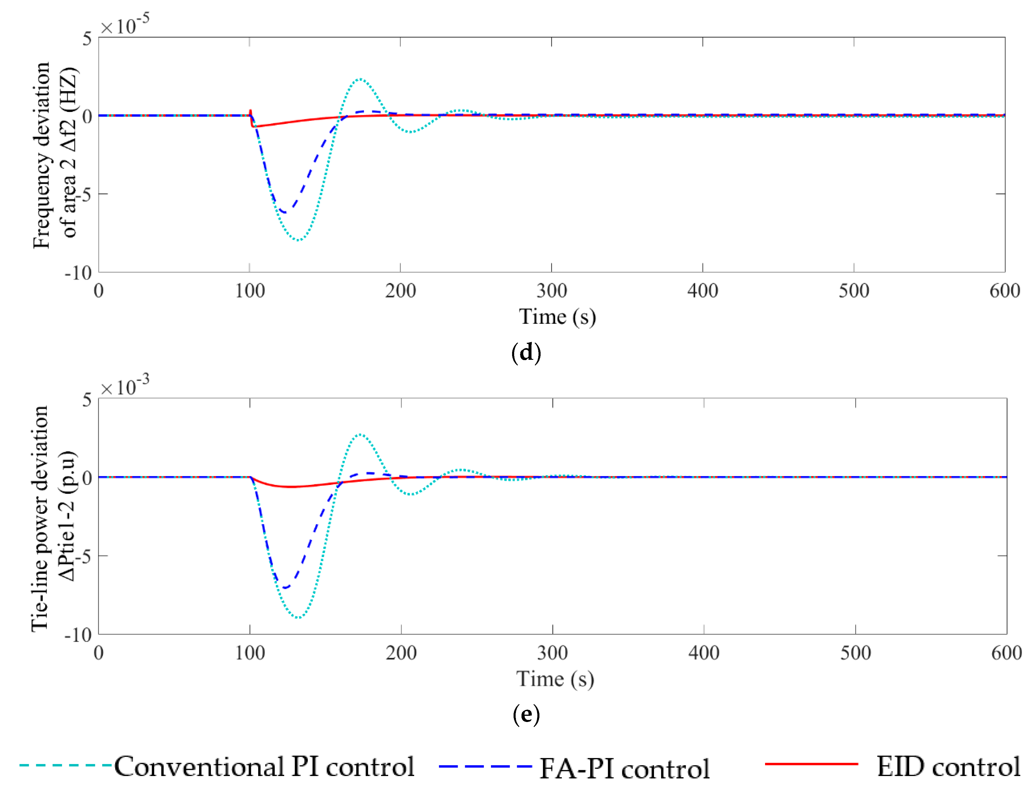
From this case, it should be noted that a +1% step load disturbance was set in the area 1 at the 100th second. The suppression performance of step load disturbance of EID control method, FA-PI control [9] method and conventional PI control method were evaluated and compared. The simulation diagram of the proposed EID method in MATLAB is shown in Figure 8. Figure 9 shows the corresponding performance of the three methods under step load disturbance. The light blue dashed line represents the conventional PI method, the dark blue dashed line is the FA-PI method, and the red solid line is the EID method. The simulation time is 600 s. Table 1 shows the performance indicators of the three methods under step load including the integral of absolute value of the error (IAE), the integral of time multiply absolute value of the error (ITAE), the integral of square error (ISE) and the integral of time multiply square error (ITSE). IAE, ITAE, ISE, ITSE are defined as follows [9]:
I A E = 0 T M A X ( | Δ f 1 | + | Δ f 2 | + | Δ P t i e 1 2 | ) d t
I T A E = 0 T M A X t ( | Δ f 1 | + | Δ f 2 | + | Δ P t i e 1 2 | ) d t
I S E = 0 T M A X ( ( Δ f 1 ) 2 + ( Δ f 2 ) 2 + ( Δ P t i e 1 2 ) 2 ) d t
I T S E = 0 T M A X t ( ( Δ f 1 ) 2 + ( Δ f 2 ) 2 + ( Δ P t i e 1 2 ) 2 ) d t
It can be seen from Figure 9 that at 130 s, the ACE and tie-line power deviations of the conventional PI control method, FA-PI control method and EID control method are 8.7 × 10⁻³ p.u, 6.3 × 10⁻³ p.u, and 6 × 10⁻⁴ p.u, respectively. Therefore, the ACE and the tie line power deviation in the proposed method is significantly smaller than that of the FA-PI method and the conventional PI method. At 108 s, the conventional PI control method and FA-PI control method have the maximum Δf1, which is 3.45 × 10⁻⁴ Hz and 3.4 × 10⁻⁴ Hz, respectively. At 150 s, the frequency of area 1 under these two control methods again has a large deviation, which is 2.8 × 10⁻⁴ Hz and 1.3 × 10⁻⁴ Hz respectively. Under the EID control method, Δf1 only has a large fluctuation of 0.4 × 10⁻⁴ Hz at 101 s. After 150 s, Δf1 under the conventional PI control method and FA-PI control method is still fluctuating, and Δf1 under the EID control method has tended to 0. The curve fluctuation of Δf2 is similar to Δf1.
Table 1 can show that the performance of the EID method is significantly better than that of the FA-PI method and the conventional PI method. Therefore, compared with the suppression performance of the FA-PI method and the conventional PI method, the EID method is more capable of suppressing step load disturbances, making the system frequency deviation smaller and the convergence speed faster.

4.3. Load Frequency Response for Random Loads

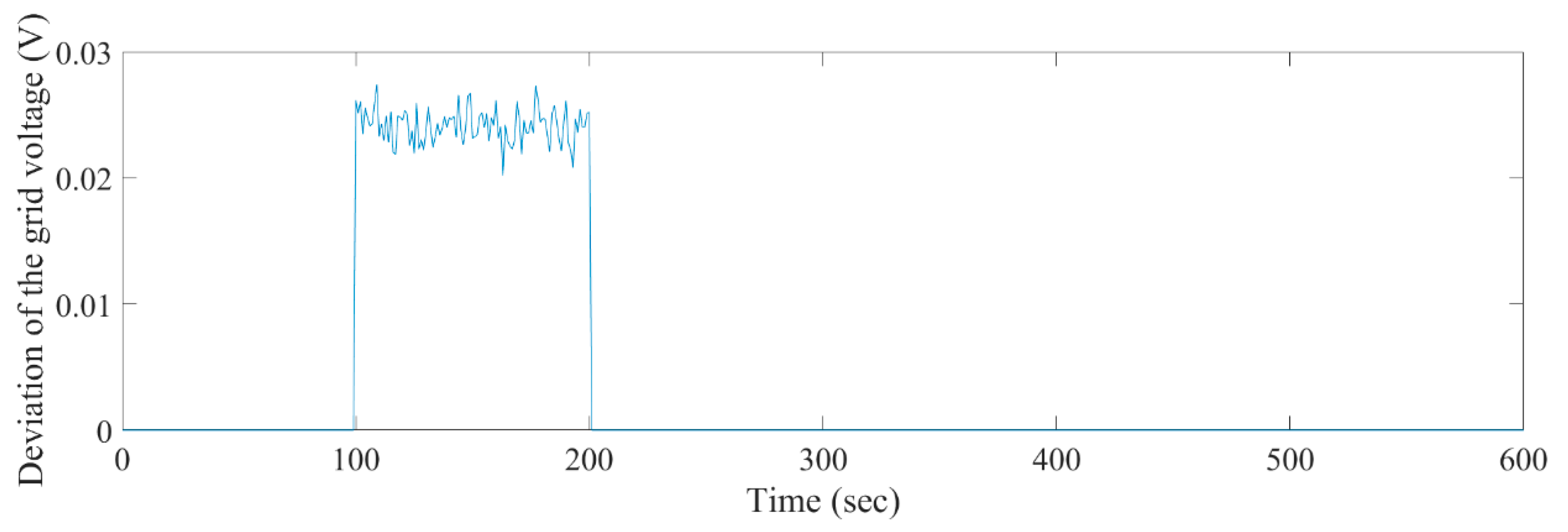
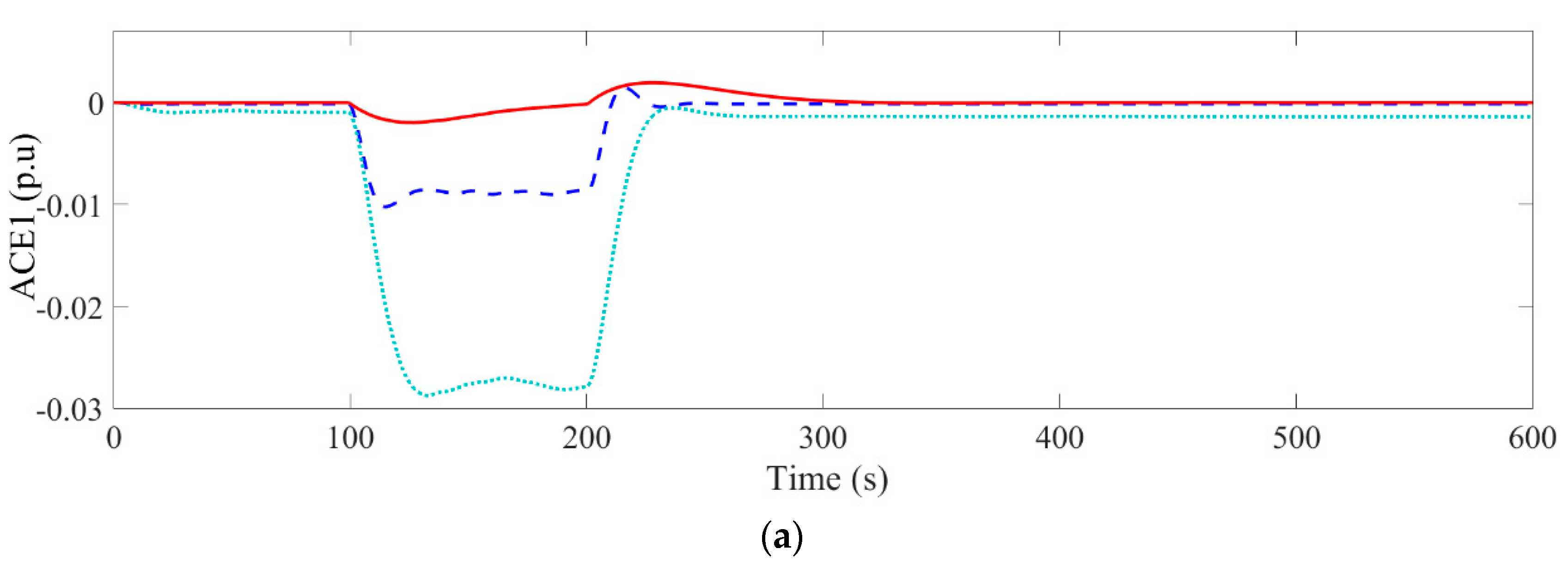
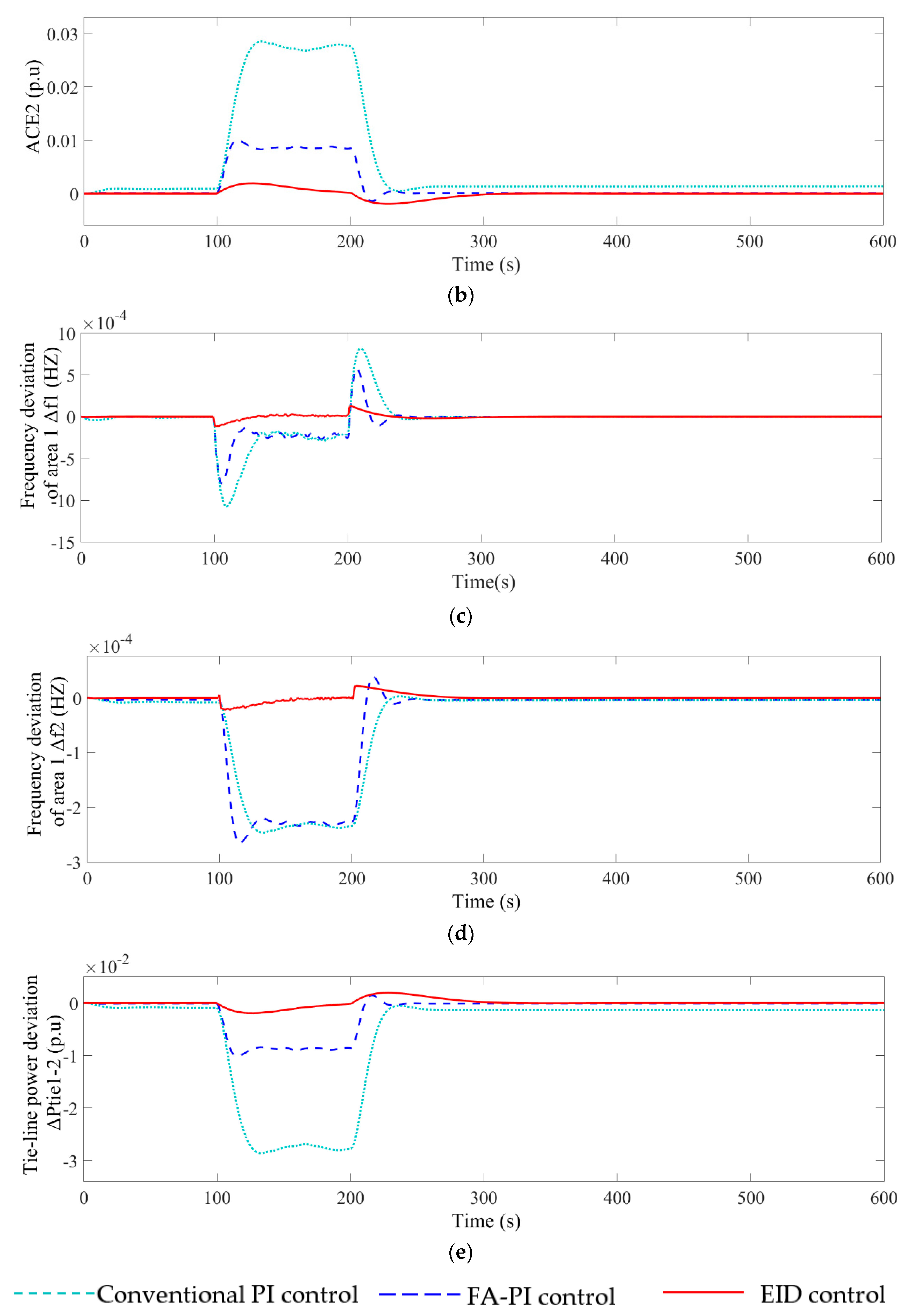
In the area 1, from the 100th second to the 200th second the PVG subsystem suffers random fluctuations of grid voltage, and there are random load disturbances in the interconnected power system. The experimental simulation diagram of this case is similar to the simulation diagram of the previous case. The simulation time is 600 s. The simulation diagrams of the two random disturbances in MATLAB are shown in Figure 10 and Figure 11. We implemented separately simulation experiments of the double EID method, the FA-PI method [9] and the conventional PI method. The simulation results are shown in Figure 12.
In Figure 12a–e, by using the EID control method, the ACE and the tie line power deviation are in the range of (−0.2 × 10⁻², 0.2 × 10⁻²) and the frequency deviation is respectively within (−1.2 × 10⁻⁴, 1.4 × 10⁻⁴) (Δf1) and (−0.22 × 10⁻⁴, 0.25 × 10⁻⁴) (Δf2). Using the FA-PI control method, the ACE and the tie line power deviation are in the range of (−1.1 × 10⁻², 0.15 × 10⁻²) and the frequency deviation is respectively within (−8 × 10⁻⁴, 6 × 10⁻⁴) (Δf1) and (−2.65 × 10⁻⁴, 0.4 × 10⁻⁴) (Δf2). Using the conventional PI control method, the ACE and the tie line power deviation are in the range of (−3 × 10⁻², 0) and the frequency deviation is respectively within (−11 × 10−4, 8.5 × 10⁻⁴) (Δf1) and (−2.5 × 10⁻⁴, 0) (Δf2). Under the EID control method, the range of ACE, tie line power deviation and frequency deviation is significantly smaller than the range under the conventional PI control method and FA-PI control method. The four performance indicators of IAE, ITAE, ISE, ITSE under the double EID method in Table 2 are at most 30% of the other two methods. Figure 12 and Table 2 show that the double EID LFC strategy is more effective in disturbance suppression than the FA-PI method and the conventional PI method when the system has both load disturbances and voltage fluctuations.

5. Conclusions

This paper proposed a load frequency control (LFC) strategy for a photovoltaic generation (PVG)-integrated multi-area interconnected power system based on double-equivalent-input disturbance (EID) controllers. Double EID controllers are used in PVG subsystems and multi-area interconnected power systems to suppress grid voltage fluctuations and load disturbances. The state feedback controller gain and observer gain in the EID controller are designed based on the system stability conditions and the perfect regulation method. The simulation results of a PVG integrated two-area interconnected power system show that the frequency deviation range of the proposed double EID method is 6% of PI method based on the firefly algorithm (FA-PI) and 7% of conventional PI method, respectively, when the grid voltage fluctuation and load disturbance exist. The double EID method is superior to the FA-PI method and the conventional PI method in terms of dynamic and steady-state performance in case of grid voltage fluctuation and load disturbance. To the best of the author’s knowledge, this work can be considered as the first contribution of EID to the optimal LFC issue of a PVG integrated multi-area interconnected power system. However, how to use the proposed double EID method to accurately estimate and compensate the impact of solar radiation changes and temperature changes in the PVG subsystem on the photovoltaic output power and frequency has always been a challenge. This also needs to be achieved in the near future.

Author Contributions

M.Y. proposed the innovative ideas behind this work and the design of the method and prepared the manuscript; Z.L., C.Y. and S.H. completed the simulation and result analysis; C.W. and Y.H. reviewed and revised the manuscript. All authors have read and agreed to the published version of the manuscript.

Funding

This work was supported by National Natural Science Foundation of China (No. 61973322).

Conflicts of Interest

The authors declare no conflict of interest.

Nomenclature

PriRegulating power of AGCp.u.MW
XgiGovernor position incrementp.u
PtiOutput power deviation of traditional generatorp.u.MW
PbiOutput power deviation of ES subsystemp.u.MW
PpviOutput power fluctuation of PVGp.u.MW
PloadiLoad disturbancep.u.MW
fiFrequency deviationHz
ACEiArea control errorp.u.MW
PtiePower change of tie linep.u.MW
TgiTime constant of governors
TtiTime constant of traditional generators
TbiTime constant of ES subsystems
KbiThe gain of ES subsystemdB
DiLoad damping coefficientp.u.MW/Hz
Mimoment of inertias.p.u.MW/Hz
Riadjustment coefficientHz/p.u.MW
(i = 1, 2 indicates the corresponding parameters of the area 1 and the area 2)

Appendix A

Table A1. System parameters values.
ParameterUnitValue
Tg1s0.3
Tt1s0.1
Tb1s0.12
Kb1dB6
D1s/Hz2.75
M1s/Hz10.5
R1Hz/p.u0.425
β1p.u/Hz0.425
Rf0.02
LfH0.001
LgH0.003
Tg2s0.3
Tt2s0.08
Tb2s0.2
KbdB5
D2s/Hz12
M2s/Hz2
R2Hz/p.u0.6
β2p.u/Hz0.6
Ttie1-2s0.25

References

  1. Ma, M.; Liu, X.; Zhang, C. LFC for multi-area interconnected power system concerning wind turbines based on DMPC. IET Gener. Transm. Distrib. 2017, 11, 2689–2696. [Google Scholar] [CrossRef]
  2. You, S.; Kou, G.; Liu, Y. Impact of high PV penetration on the inter-area oscillations in the U.S. eastern interconnection. IEEE Access 2017, 5, 4361–4369. [Google Scholar] [CrossRef]
  3. Yang, W.; Zhou, X.; Xue, F. Impacts of large scale and high voltage level photovoltaic penetration on the security and stability of power system. In Proceedings of the Asia-Pacific Power and Energy Engineering Conference, Chengdu, China, 28–31 March 2010. [Google Scholar]
  4. Eftekharnejad, S.; Vittal, V.; Heydt, G.T.; Keel, B.; Loehr, J. Impact of increased penetration of photovoltaic generation on power systems. IEEE Trans. Power Syst. 2013, 28, 893–901. [Google Scholar] [CrossRef]
  5. Tamimi, B.; Canizares, C.; Bhattacharya, K. System stability impact of large-scale and distributed solar photovoltaic generation: The case of Ontario, Canada. IEEE Trans. Sustain. Energy 2013, 4, 680–688. [Google Scholar] [CrossRef]
  6. Liu, Y.; Zhu, L.; Zhan, L.; Gracia, J.R.; King, T.J. Active power control of solar PV generation for large interconnection frequency regulation and oscillation damping. Int. J. Energy Res. 2016, 40, 353–361. [Google Scholar] [CrossRef]
  7. Eftekharnejad, S.; Vittal, V.; Heydt, G.T.; Keel, B.; Loehr, J. Small signal stability assessment of power systems with increased penetration of photovoltaic generation: A case study. IEEE Trans. Sustain. Energy 2013, 4, 960–967. [Google Scholar] [CrossRef]
  8. Quintero, J.; Vittal, V.; Heydt, G.T.; Zhang, H. The impact of increased penetration of converter control-based generators on power system modes of oscillation. IEEE Trans. Power Syst. 2014, 29, 2248–2256. [Google Scholar] [CrossRef]
  9. Abd-Elazim, S.M.; Ali, E.S. Load frequency controller design of a two-area system composing of PV grid and thermal generator via firefly algorithm. Neural Comput. Appl. 2018, 30, 607–616. [Google Scholar] [CrossRef]
  10. Sa-ngawong, N.; Ngamroo, I. Intelligent photovoltaic farms for robust frequency stabilization in multi-area interconnected power system based on PSO-based optimal Sugeno fuzzy logic control. Renew. Energy 2015, 74, 555–567. [Google Scholar] [CrossRef]
  11. Mi, Y.; Yang, F.; Li, D.; Wang, C.; Loh, P.C.; Wang, P. The sliding mode load frequency control for hybrid power system based on disturbance observer. Int. J. Electr. Power Energy Syst. 2016, 74, 446–452. [Google Scholar] [CrossRef]
  12. Zeng, G.; Xie, X.; Chen, M. An adaptive model predictive load frequency control method for multi-area interconnected power systems with photovoltaic generations. Energies 2017, 10, 1840. [Google Scholar] [CrossRef] [Green Version]
  13. Saxena, S.; Hote, Y.V. Decentralized PID load frequency control for perturbed multi-area power systems. Int. J. Electr. Power Energy Syst. 2016, 81, 405–415. [Google Scholar] [CrossRef]
  14. Ray, P.K.; Mohanty, S.R.; Kishor, N. Proportional–integral controller based small-signal analysis of hybrid distributed generation systems. Energy Conv. Manag. 2011, 52, 1943–1954. [Google Scholar] [CrossRef]
  15. Singh, V.P.; Kishor, N.; Samuel, P. Improved load frequency control of power system using LMI based PID approach. J. Frankl. Inst. Eng. Appl. Math. 2017, 354, 6805–6830. [Google Scholar] [CrossRef]
  16. Pandi, V.R.; Al-Hinai, A.; Feliachi, A. Coordinated control of distributed energy resources to support load frequency control. Energy Conv. Manag. 2015, 105, 918–928. [Google Scholar] [CrossRef]
  17. Ali, E.S.; Abd-Elazim, S.M. BFOA based design of PID controller for two area Load Frequency Control with nonlinearities. Int. J. Electr. Power Energy Syst. 2013, 51, 224–231. [Google Scholar] [CrossRef]
  18. Bendjedia, M.; Tehrani, K.A.; Azzouz, Y. Design of RST and fractional order PID controllers for an induction motor drive for electric vehicle application. In Proceedings of the 7th IET International Conference on Power Electronics, Machines and Drives, Manchester, UK, 8–10 April 2014. [Google Scholar]
  19. Kouba, N.E.; Menaa, M.; Hasni, M.; Tehrani, K.; Boudour, M. A novel optimized fuzzy-PID controller in two-area power system with HVDC link connection. In Proceedings of the International Conference on Control, Decision and Information Technologies (CoDIT), St. Paul’s Bay, Malta, 6–8 April 2016; pp. 204–209. [Google Scholar]
  20. Aziz, S.; Wang, H.; Liu, Y.; Peng, J.; Jiang, H. Variable universe fuzzy logic-based hybrid LFC control with real-time implementation. IEEE Access 2019, 7, 25535–25546. [Google Scholar] [CrossRef]
  21. Sudha, K.R.; Santhi, R.V. Load frequency control of an interconnected reheat thermal system using type-2 fuzzy system including SMES units. Int. J. Electr. Power Energy Syst. 2012, 43, 1383–1392. [Google Scholar] [CrossRef]
  22. Ghafouri, A.; Milimonfared, J.; Gharehpetian, G.B. Fuzzy-adaptive frequency control of power system including microgrids, wind farms, and conventional power plants. IEEE Syst. J. 2018, 12, 2772–2781. [Google Scholar] [CrossRef]
  23. Yousef, H.A.; AL-Kharusi, K.; Albadi, M.H.; Hosseinzadeh, N. Adaptive fuzzy logic load frequency control of multi-area power system. Int. J. Electr. Power Energy Syst. 2015, 68, 384–395. [Google Scholar] [CrossRef]
  24. Datta, M.; Senjyu, T. Fuzzy control of distributed PV inverters/energy storage systems/electric vehicles for frequency regulation in a large power system. IEEE Trans. Smart Grid 2013, 4, 479–488. [Google Scholar] [CrossRef]
  25. Prasad, S.; Purwar, S.; Kishor, N. Load frequency regulation using observer based non-linear sliding mode control. Int. J. Electr. Power Energy Syst. 2019, 104, 178–193. [Google Scholar] [CrossRef]
  26. Baghaee, H.R.; Mirsalim, M.; Gharehpetian, G.B.; Talebi, H.A. Decentralized sliding mode control of WG/PV/FC microgrids under unbalanced and nonlinear load conditions for on-and off-grid modes. IEEE Syst. J. 2018, 12, 3108–3119. [Google Scholar] [CrossRef]
  27. Kalla, U.K.; Singh, B.; Murthy, S.S.; Jain, C.; Kant, K. Adaptive sliding mode control of standalone single-phase microgrid using hydro, wind, and solar PV array-based generation. IEEE Trans. Smart Grid 2018, 9, 6806–6814. [Google Scholar] [CrossRef]
  28. Dhar, S.; Dash, P.K. A new backstepping finite time sliding mode control of grid connected PV system using multivariable dynamic VSC model. Int. J. Electr. Power Energy Syst. 2016, 82, 314–330. [Google Scholar] [CrossRef]
  29. Mi, Y.; He, X.; Hao, X.; Li, Z. Frequency control strategy of multi-area hybrid power system based on frequency division and sliding mode algorithm. IET Gener. Transm. Distrib. 2019, 13, 1145–1152. [Google Scholar] [CrossRef]
  30. Wang, C.; Mi, Y.; Fu, Y.; Wang, P. Frequency control of an isolated micro-grid using double sliding mode controllers and disturbance observer. IEEE Trans. Smart Grid 2016, 9, 923–930. [Google Scholar] [CrossRef]
  31. Ma, M.; Chen, H.; Liu, X. Distributed model predictive load frequency control of multi-area interconnected power system. Int. J. Electr. Power Energy Syst. 2014, 62, 289–298. [Google Scholar] [CrossRef]
  32. Mohamed, T.H.; Bevrani, H.; Hassan, A.A.; Hiyama, T. Decentralized model predictive based load frequency control in an interconnected power system. Energy Convers. Manag. 2011, 52, 1208–1214. [Google Scholar] [CrossRef]
  33. Liu, X.; Zhang, Y.; Lee, K.Y. Coordinated distributed MPC for load frequency control of power system with wind farms. IEEE Trans. Ind. Electron. 2017, 64, 5140–5150. [Google Scholar] [CrossRef]
  34. Ersdal, A.M.; Imsland, L.; Uhlen, K. Model predictive load-frequency control. IEEE Trans. Power Syst. 2016, 31, 777–785. [Google Scholar] [CrossRef] [Green Version]
  35. Sun, X.; Liao, K.; Yang, J.; He, Z. Model predictive control based load frequency control for power systems with wind turbine generators. In Proceedings of the IEEE Innovative Smart Grid Technologies—Asia (ISGT Asia), Chengdu, China, 18 November 2019; pp. 1387–1392. [Google Scholar]
  36. Banis, F.; Guericke, D.; Madsen, H.; Poulsen, N.K. Load frequency control in microgrids using target-adjusted MPC. IET Renew. Power Gener. 2020, 14, 118–124. [Google Scholar] [CrossRef] [Green Version]
  37. She, J.; Xin, X.; Ohyama, Y. Estimation of equivalent input disturbance improves vehicular steering control. IEEE Trans. Veh. Technol. 2007, 56, 3722–3731. [Google Scholar] [CrossRef]
  38. Liu, F.; Ma, J. Equivalent input disturbance-based robust LFC strategy for power system with wind farms. IET Gener. Transm. Distrib. 2018, 12, 4582–4588. [Google Scholar] [CrossRef]
  39. Sun, Y.; Ulsoy, A.G.; Nelson, P.W. Design of observer-based feedback control for time-delay systems with application to automotive powertrain control. J. Frankl. Inst. 2010, 347, 358–376. [Google Scholar]
  40. She, J.; Fang, M.; Ohyama, Y.; Hashimoto, H.; Wu, M. Improving disturbance-rejection performance based on an equivalent-input- disturbance approach. IEEE Trans. Ind. Electron. 2008, 55, 380–389. [Google Scholar] [CrossRef]
  41. Liu, S.; Liu, X.P.; El Saddik, A. Load frequency control for wide area monitoring and control system (WAMC) in power system with open communication links. In Proceedings of the Power Engineering and Automation Conference (PEAM), Wuhan, China, 18–20 September 2012. [Google Scholar]
  42. Vafamand, N.; Khooban, M.H.; Dragičević, T.; Boudjadar, J.; Asemani, M.H. Time-delayed stabilizing secondary load frequency control of shipboard microgrids. IEEE Syst. J. 2019, 13, 3233–3241. [Google Scholar] [CrossRef]
  43. Ahmadi, A.; Aldeen, M. An LMI approach to the design of robust delay-dependent overlapping load frequency control of uncertain power systems. Int. J. Electr. Power Energy Syst. 2016, 81, 48–63. [Google Scholar] [CrossRef]
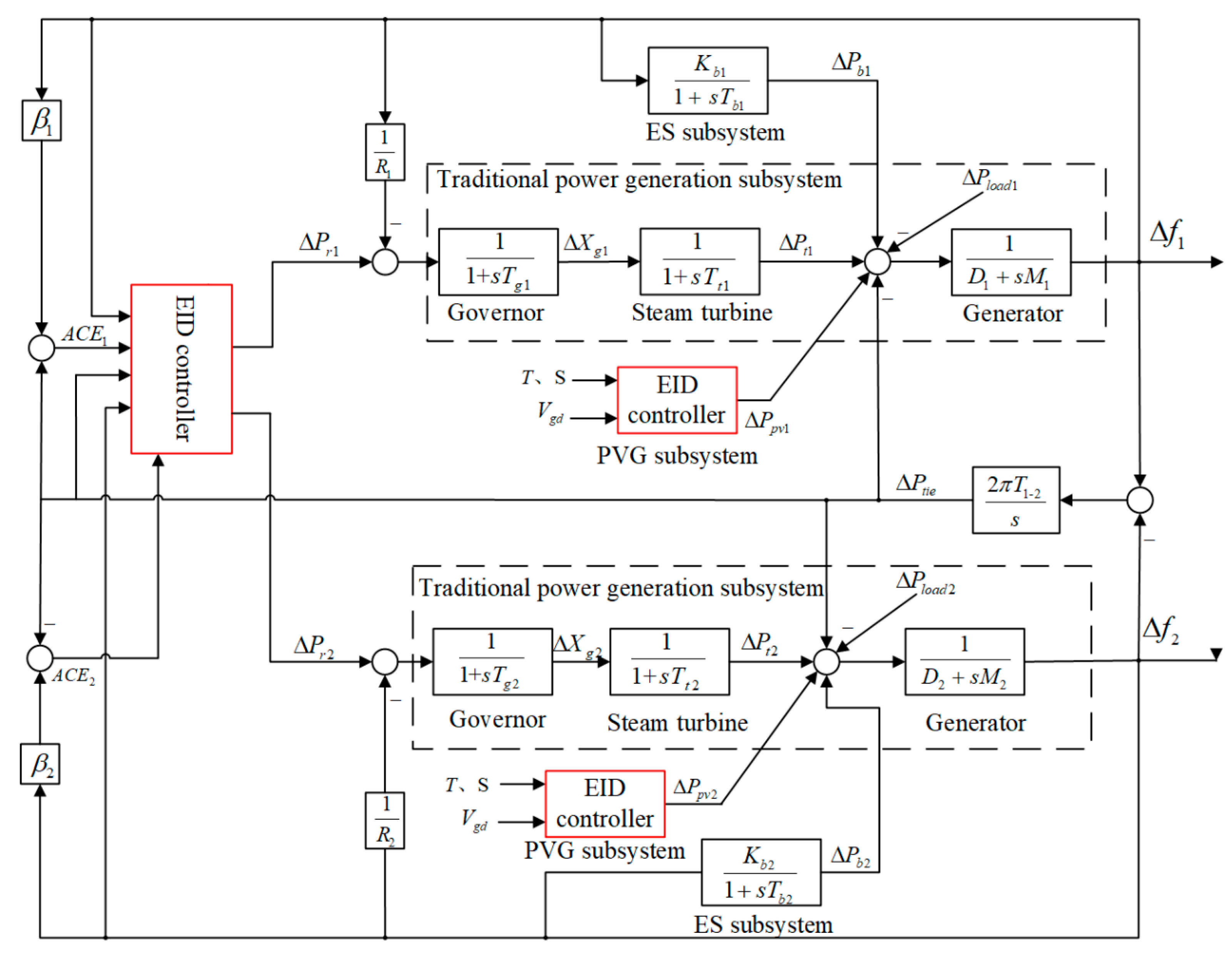
Figure 1. The PVG integrated two-area interconnected power system.
Energies 13 06103 g001
Figure 2. Grid connection block diagram of a PV generator.
Energies 13 06103 g002
Figure 3. EID controller.
Energies 13 06103 g003
Figure 4. Equivalent block diagram of EID controller.
Energies 13 06103 g004
Figure 5. The redrawn EID based system.
Energies 13 06103 g005
Figure 6. EID-based PVG subsystem.
Energies 13 06103 g006
Figure 7. Response of the PVG subsystem to voltage sag of power grid: (a) the grid voltage, (b) the inverter output current, (c) the inverter output power.
Energies 13 06103 g007aEnergies 13 06103 g007b
Figure 8. Simulation diagram of the proposed EID method.
Energies 13 06103 g008
Figure 9. Responses of the two-area interconnected power system to the areas 1 and 2 step load disturbances: (a) ACE in the area 1, (b) ACE in the area 2, (c) frequency deviation of the area 1, (d) frequency deviation of the area 2, (e) power deviation of tie line between the areas 1 and 2.
Energies 13 06103 g009aEnergies 13 06103 g009b
Figure 10. The random fluctuations of grid voltage.
Energies 13 06103 g010
Figure 11. The random load disturbances.
Energies 13 06103 g011
Figure 12. Response of random disturbance in the area 1: (a) ACE in the area 1, (b) ACE in the area 2, (c) frequency deviation of the area 1, (d) frequency deviation of the area 2, (e) power deviation of tie line between the areas 1 and 2
Energies 13 06103 g012aEnergies 13 06103 g012b
Table 1. Performance comparison of EID, FA-PI, and conventional PI under step load disturbance.
MethodIAEITAEISEITSE
Conventional PI0.443364.730.0024710.3299
FA-PI [9]0.251732.640.0012250.1543
Double EID0.038765.5561.699·10−50.002297
Table 2. Performance comparison of double EID, FA-PI, and conventional PI under two random disturbances.
MethodIAEITAEISEITSE
Conventional PI3.102564.60.0690711.23
FA-PI [9]1.0171680.0076951.189
EID0.301153.10.00063250.1019
Publisher’s Note: MDPI stays neutral with regard to jurisdictional claims in published maps and institutional affiliations.