Article

Design and Performance Analysis of a Saturated Iron-Core Superconducting Fault Current Limiter for DC Power Systems

1
Department of Electrical Engineering, Changwon National University, Changwon 51140, Korea
2
Department of Industrial Engineering, University of Bologna, 40126 Bologna BO, Italy
*
Author to whom correspondence should be addressed.
Energies 2020, 13(22), 6090; https://doi.org/10.3390/en13226090
Submission received: 23 October 2020 / Revised: 13 November 2020 / Accepted: 19 November 2020 / Published: 20 November 2020
(This article belongs to the Special Issue Protection of Future Multi-Terminal HVDC Grids)

Abstract

:
A saturated iron-core superconducting fault current limiter (SI-SFCL) can significantly limit the magnitude of the fault current and reduce the stress on circuit breakers in direct current (DC) power systems. The SI-SFCL consists of three main parts: one magnetic iron-core, one normal conductive primary coil (CPC), and one superconducting secondary coil (SSC). This paper deals with the design options for the coil system of the SI-SFCL and confirms their operating characteristics through a physical experiment. The electromagnetic characteristics and operational features of the SI-SFCL was analyzed by a 3D finite element method simulation model. The design of the SSC was based on shape, wire types, required fault current limit and protection aspects. In the CPC, the bobbin was designed based on material selection, cost, structural design, and the effects of the SI-SFCL on the fault current limit. Based on these simulation results, a laboratory-scale SI-SFCL was developed, specifically fabricated to operate on a 500 V, 50 A direct current (DC) power system. In the experiment, the operating characteristics of each coil were analyzed, and the fault current limit of the SI-SFCL according to the operating currents of the SSC and bobbin design of the CPC were confirmed. Finally, the cost analysis of the SI-SFCL with the proposed design options of the coil system was implemented. The results obtained through this study can be effectively used to large-scale SI-SFCL development studies for high-voltage direct current (HVDC) power systems.

1. Introduction

In recent years, with the increase in the grid connection of new and renewable energy generation facilities and the advent of smart grids, interest in research on multi-terminal high-voltage direct current transmission through a voltage source converter (VSC-HVDC) has been increasing [1]. Compared with a traditional HVDC power system based on a line-commuted converter, the VSC-HVDC power system has merits, such as the flexible control of active and reactive power, high power quality even without harmonic filters, and easy connection to a weak alternating current (AC) system. Therefore, the VSC-HVDC power system is expected to be further developed and widely used in the electric power industry in the future. However, one of the major challenges in the operation of a VSC-HVDC power system is to limit and block the DC fault current. Due to the characteristics of the converter structure and the control strategy of the VSC-HVDC power system, very high magnitude and fast rise rates of the DC fault currents are experienced. These make the internal components of the converter susceptible to damage; thus, these components must be protected from the DC fault currents [2]. Unlike AC system, there is no zero-crossing point in DC, making it hard to interrupt a large short-circuit fault current with a conventional DC circuit breaker (DCCB) [3,4,5,6,7,8]. Therefore, a current limiting device is required to limit the DC fault current to a relatively low level. A superconducting fault current limiter (SFCL) is one type of the current limiting devices which can limit the fault current quickly and significantly reduce the stress on the DCCB in VSC-HVDC power systems based on its inherent physical characteristics [9].
Recently, most SFCL studies for application in DC power systems have been resistive and inductive saturated-iron core types [10,11,12,13,14,15,16]. The equivalent electrical circuit of a resistive type SFCL (R-SFCL) is shown in Figure 1. The R-SFCL is the simplest and most compact SFCL design and directly uses the quench properties of a superconductor. During normal operation, the superconducting coil (SC) carries a normal DC current with zero resistance. In the event of a fault, the current increases rapidly, exceeding the critical current level, causing the SC to quench and increasing the resistance to limit the fault current. The shunt resistor is normally located in parallel with the SC to avoid overvoltage in case the resistance of the SC increases too rapidly after the fault current occurs. However, the quenching process and the temperature rise in the SC can affect and reduce the reliability and stability of the R-SFCL operation. The R-SFCL also requires a superconducting wire long in length and complex design in high-voltage, large-capacity DC power systems.
A saturated iron-core SFCL (SI-SFCL) applied to a DC power system is described in Figure 2. Unlike the R-SFCL, the SI-SFCL uses the magnetic properties of iron-core to change the inductance to limit the magnitude of the fault current. Since the DC grid current does not flow directly into the superconducting coil, no quench occurs. Thus, the SI-SFCL is more suitable for high-voltage and large-capacity DC power systems. The disadvantages of the SI-SFCL are bulky size, heavy weight due to its iron-core, high cost, and the complex design of the coil system. Although several recent studies have proposed the conceptual designs and simulation analysis of the SI-SFCL for DC power systems, there are still no experimental studies verifying its operational performance while considering the issues related to its optimal design for practical applications [17,18,19,20,21].
In this paper, the authors propose a design process and options for the coil system of the SI-SFCL, and confirm their operating characteristics through both simulations and an experiment. The design target of the SI-SFCL for the fault current limitation rate was 70%. The designed structure of the SI-SFCL included three main parts: one normal conductive primary coil (CPC) directly connected to the DC grid, one single rectangular magnetic iron-core, and one superconducting secondary coil (SSC) biased by a DC current source. A 3D finite element method (FEM) model was built to analyze the electromagnetic characteristics and operational features of the SI-SFCL. The coil systems, including the CPC and SSC, were designed to achieve the required fault current limit performance and reduce the cost of the SI-SFCL system. The design of the SSC was based on shape, wire type, required fault current limit and protection aspects. The bobbin design of the CPC was implemented based on the material selection, structure, and its effects on the fault current limit of the SI-SFCL. We considered a CPC design with three kinds of bobbins, including solid aluminum (Al-solid), cutting aluminum (Al-cutting), and solid glass fiber reinforced polymer (GFRP) bobbins. A laboratory-scale SI-SFCL was developed, manufactured, and tested for a 500 V, 50 A DC power system. In the experiment, the operating characteristics of each coil were analyzed. The fault current limit of the SI-SFCL according to the operating currents of the SSC and the bobbin designs of the CPC were tested and compared with each other. The total cost of the SI-SFCL with the proposed design options of the coil system was also analyzed in detail.
As a result, the designed SI-SFCL could effectively limit the fault current in the DC power system. The design options of the CPC and SSC was able to improve the operating performance and reduce costs in SI-SFCL design. The results obtained in this study can be effectively applied to large-scale SI-SFCL development studies for VSC-HVDC power systems.

2. Conceptual Design of the SI-SFCL for a DC Power System

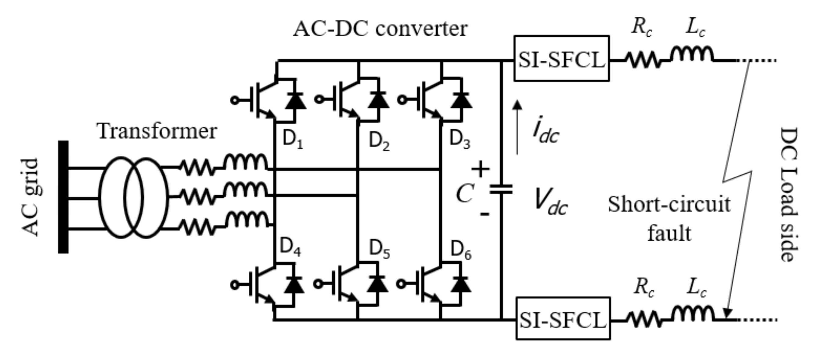
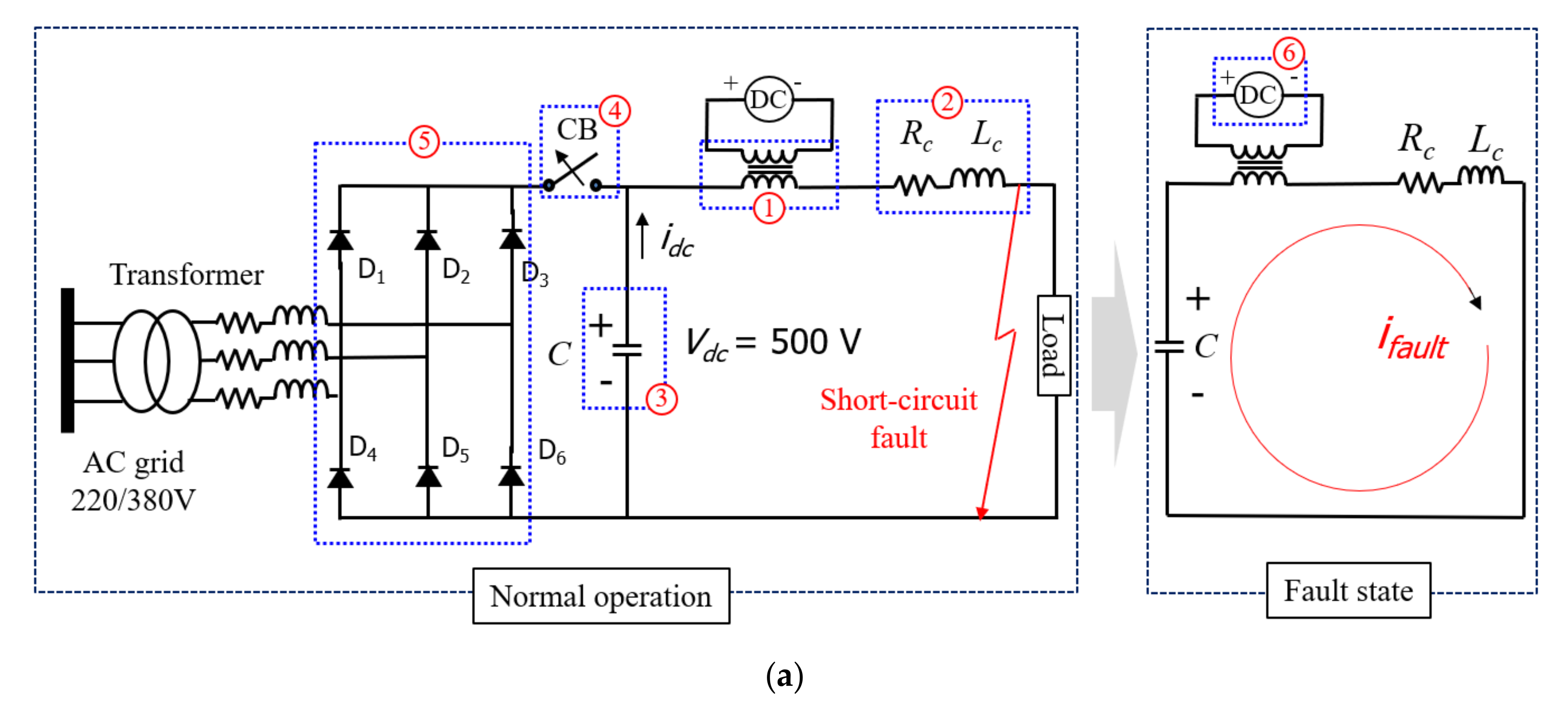
2.1. Fault Current Characteristic in the VSC-DC Power System

The SI-SFCL is the most widely used inductive type SFCL and has been developed for using in several AC systems [22,23,24,25]. The SI-SFCL in this study was applied to limit the fault current of the VSC-DC power system, as described in Figure 3. When a DC short-circuit fault occurs on the DC side of the VSC, the insulated-gate bipolar transistors (IGBTs) immediately block itself for self-protection. At this time, the capacitor voltage, Vdc, is higher than the peak value of the AC side inter-phase voltage, and the AC side system cannot supply power to the DC side system through the free-wheel diodes due to reverse voltage [20,21,26]. As a result, the DC side system is separated from the AC side, and the AC side current drops to zero. At this state, the DC side can be considered as a circuit in which the capacitor discharges into the short-circuit point. The capacitor discharges rapidly, and the DC current becomes very large, which causes a great threat to the safety of the capacitor and diodes. However, the installed SI-SFCL can reduce the fault current level, as well as the discharge of the capacitor, and the DC power system will be safe. Then, the breaking capacity of the DCCBs could be reduced.
In this study, the fault current limit characteristics of the SI-SFCL in a transient process in which the capacitor discharges to the short-circuit point were analyzed through a simulation and experiment.

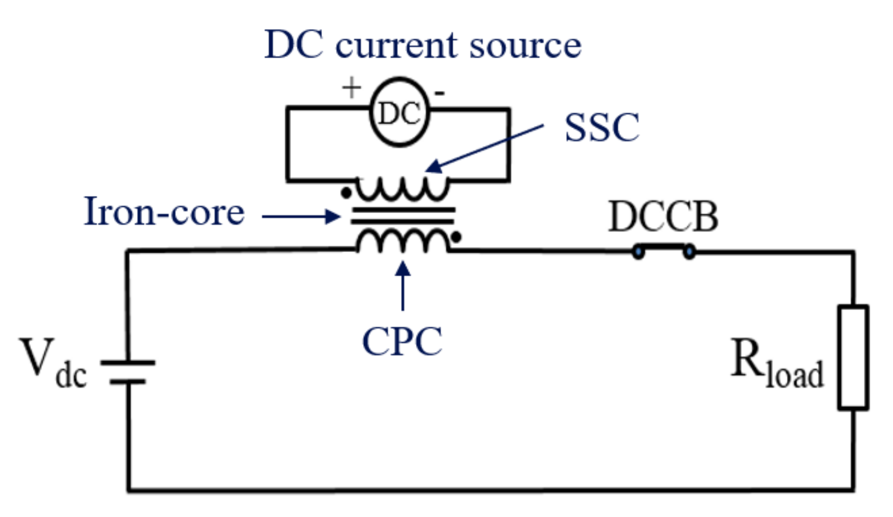
2.2. Configuration and Specifications of the Lab-Scale SI-SFCL

The designed structure of the SI-SFCL described in Figure 4 includes one CPC directly connected to the DC power system, one rectangular-shaped iron-core, and one excitation SSC supplied the current by a DC bias source. The CPC and SSC generate magnetic fields in opposite directions.
During normal operation, the DC bias current of the SSC generates a much higher and opposite magnetic field (Bsec) compared to that of the CPC (Bpri), which saturates the iron-core. The permeability of the iron-core is quite small and the inductance of the CPC is extremely low; thereby there is no effect on the DC network operation. When a DC short-circuit fault happens and a high current flow through the CPC, the iron-core is driven out of the saturated state in the linear region, so the inductance of the CPC increases rapidly and suppresses the rise of the fault current. Another advantage of the SI-SFCL is the possibility to regulate the fault current limit ability by controlling the operating current of the SSC.
In order to prove the operating performance of the designed SI-SFCL and the effectiveness of the coil designs through experiments, a lab-scale SI-SFCL was developed. We decided to perform the SI-SFCL in a 500 V, 50 A DC power system. The initial specifications of the designed SI-SFCL were determined, as shown in Table 1, and the detailed design process was presented in the previous research article [27]. The major drawbacks of the SI-SFCL technology include its large volume, heavy weight, high cost, complex design of the SSC, and losses in the iron-core and CPC. Therefore, it is necessary to select options that reduce the impact of these factors and increase performance, economy, and efficiency through an appropriate design process. In this study, we discussed the optimal design of the SSC and CPC to improve the SI-SFCL performance, as well as the economics of a DC power system.

3. Design of the Coil System for the Lab-Scale SI-SFCL

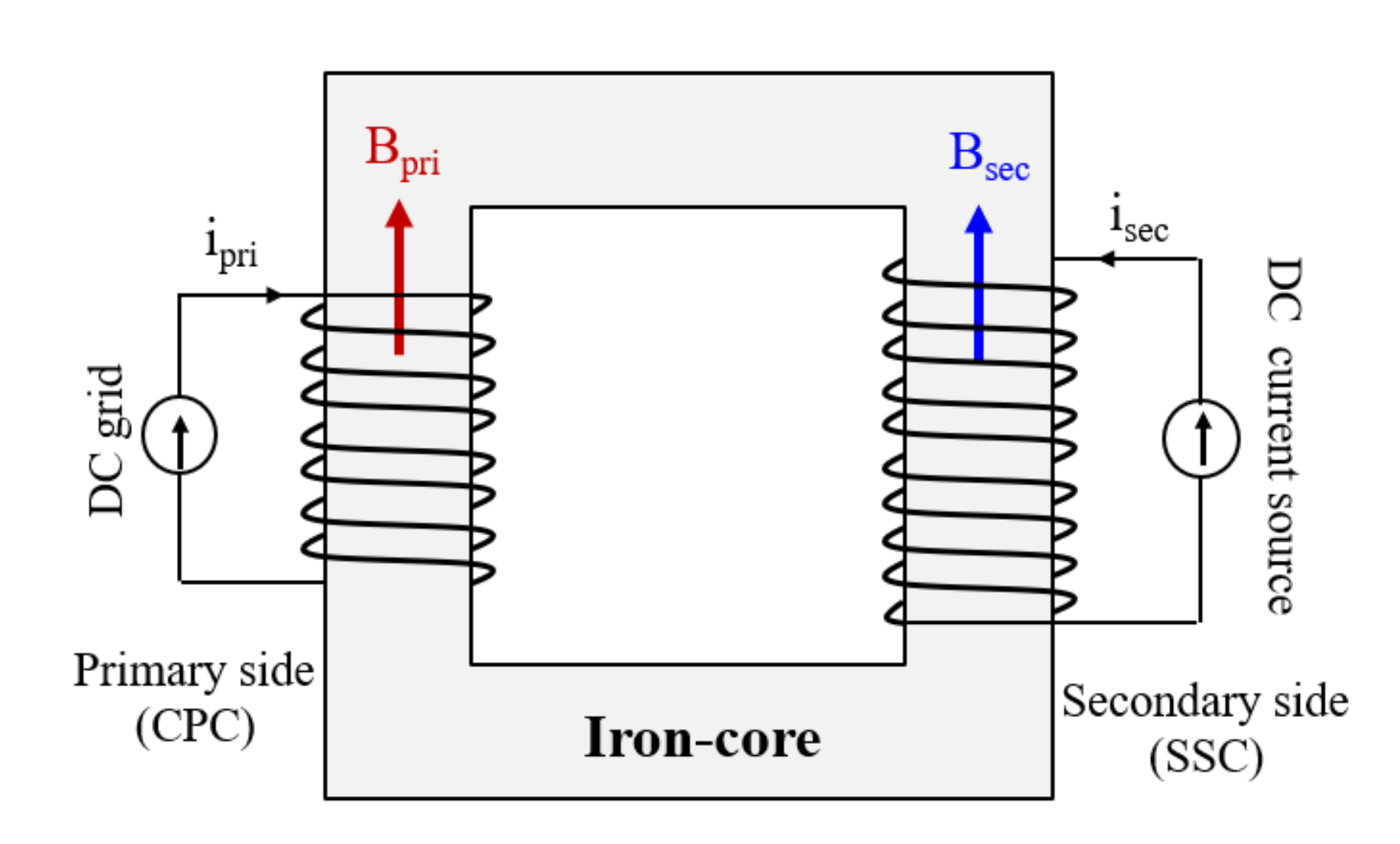
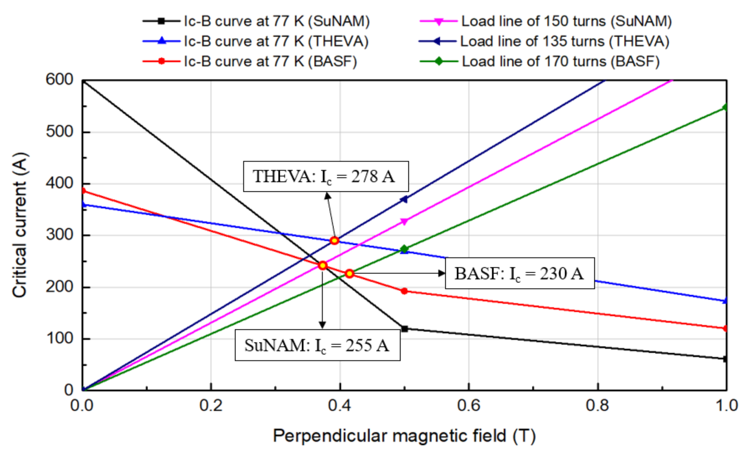
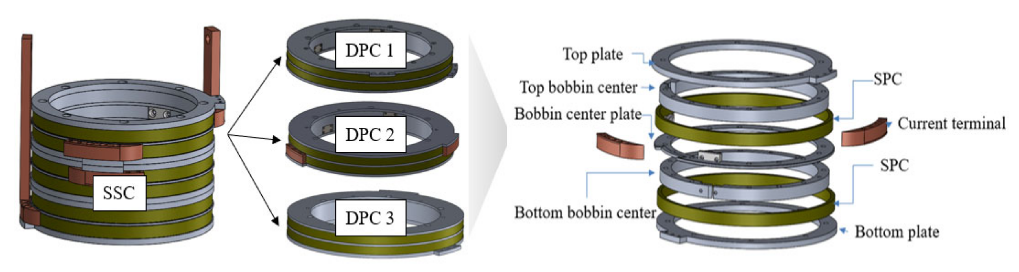
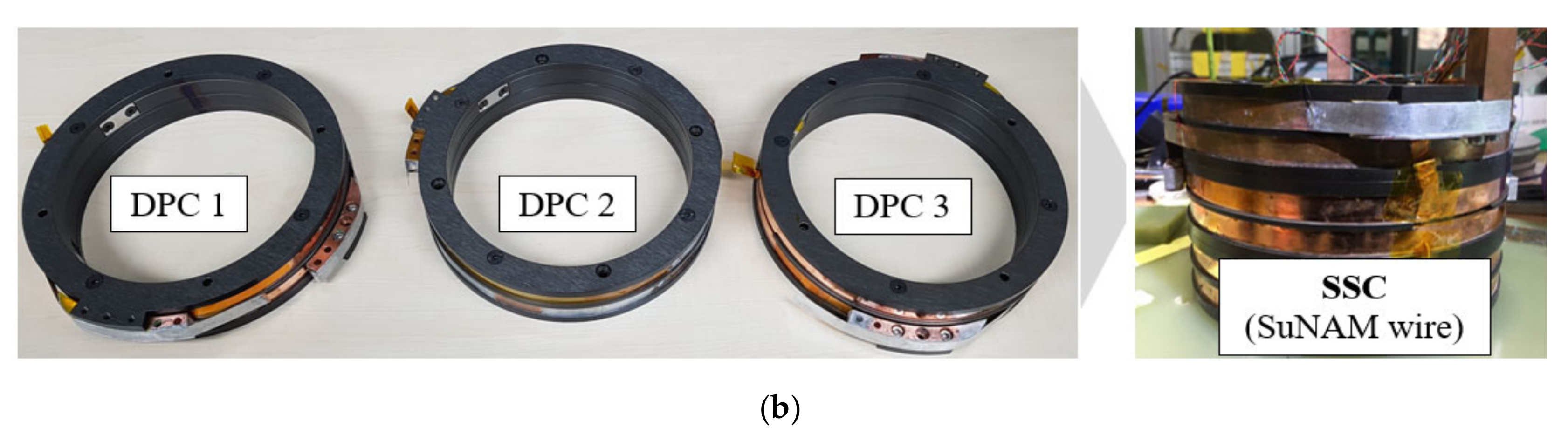
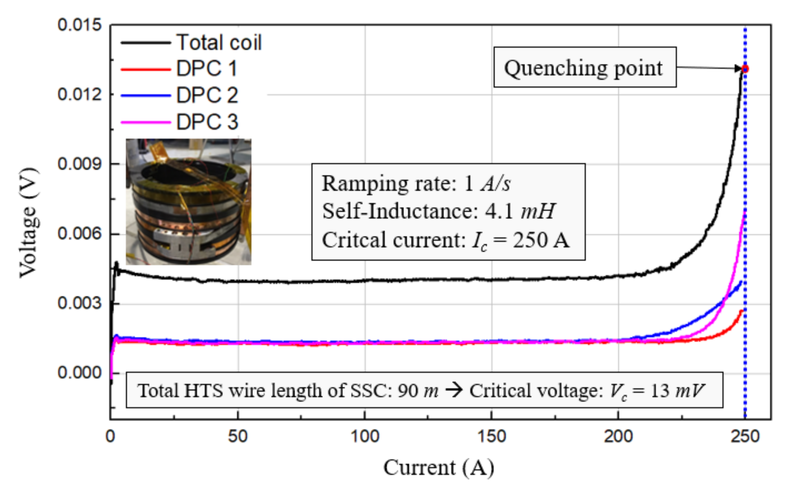
3.1. Design of the SSC

The first consideration covers the design options for the SSC, which are complex and expensive to design. The SSC design and comparative analysis results using various superconducting wires are presented. Based on the targeted fault current limit, the SSC was designed in terms of its size, number of turns, operating current, operating temperature, required wire length, and total wire cost. The size and shape of the SSC depends on the size of the iron-core, which is calculated based on the rated power of the DC power system [27]. The selection of superconducting wire type is an important issue to minimize the cost of the SSC design. The second-generation high-temperature superconducting (2G HTS) wire was selected, as it can be operated at a temperature of 77 K (cooled by liquid nitrogen). We investigated three different kinds of 2G HTS wires—A1, A2, and A3—which are manufactured by the SuNAM CO., LTD in Anseong, South Korea; THEVA Pro-Line Superconductors in Ismaning, Germany; and BASF New Business GmbH in Ludwigshafen, Germany, respectively. The detailed specifications of each 2G HTS wire are summarized in Table 2. The A1 wire has a higher critical current density than the other wires, and the A3 wire has the advantage of being the cheapest.
The number of turns for the CPC was calculated to be 198. The SSC is designed so that the fault current limit rate of the SI-SFCL approaches 70%. The fault current limit ability of the SI-SFCL was verified through the PSCAD/EMTDC simulation model. A FEM model was developed to analyze the magnetic flux density of the SSC and estimate its critical current. The operating current of the SSC was determined with a safety margin of at least 20%. The critical current of the SSC depends on the magnetic flux density in the perpendicular direction of the wire surface. Therefore, the critical current was estimated by comparing the value of the perpendicular magnetic flux density and the Ic-B curves of the 2G HTS wires, as shown in Figure 5. As a result, the number of turns of the SSC with the A1, A2, and A3 wires was determined to be 150, 135, and 170 turns, respectively. Accordingly, their operating currents were 200 A, 220 A, and 230 A. The detailed specifications of the SSCs using these three kinds of 2G HTS wires are described and compared in Table 3.
With the same shape, inner radius, safety margin of the operating current, and fault limiting performance, the SSC with the A1 wire exhibited the lowest wire cost; thus, wire A1 was chosen. Circular-shaped double pancake coils (DPCs) were applied to the SSC, and three DPCs were used. Each DPC consisted of two single pancake coils (SPC). The number of turns of one DPC was 50. The height, inner and outer radii of the SSC were 105.6 mm, 92 mm, and 97.5 mm, respectively. In the fault event, the high voltage and current induced into the SSC can damage the SSC and DC bias source and affect the fault limiting performance of the SI-SFCL. Thus, in order to protect the superconducting coil from these factors, the SSC was wound on the anodizing aluminum bobbin with turn to turn Kapton insulation. The aluminum bobbin applied to the SSC is like a shield that isolates the SSC from the magnetic flux change in the iron-core during the fault condition; thus, it can reduce the induced current and voltage in the SSC. Figure 6 describes the detailed structure of the designed SSC for the lab-scale SI-SFCL.

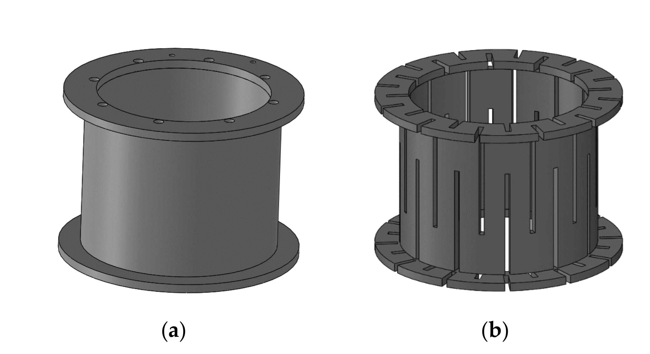
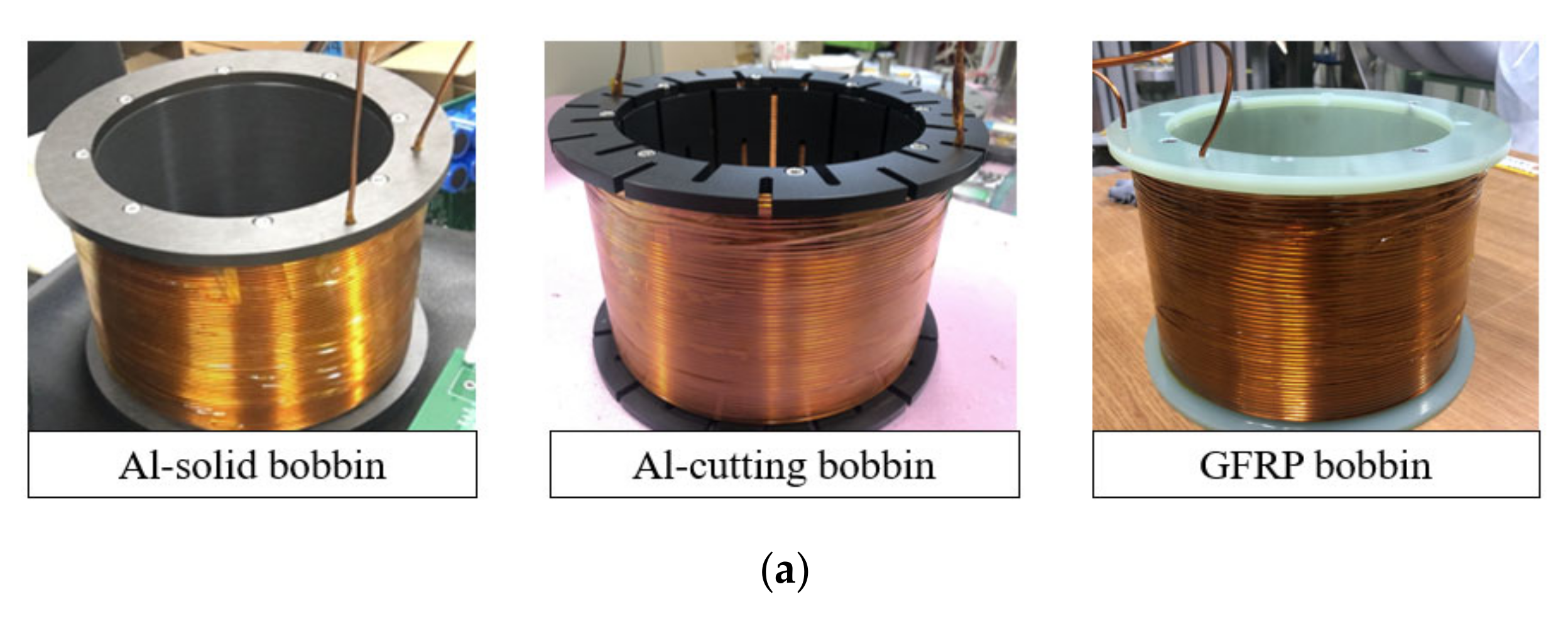
3.2. Design of the CPC

On principle, the SI-SFCL uses the iron-core magnetic properties to change the inductance of the CPC to limit the magnitude of the fault current. The fault current in the VSC-DC power system is caused by the capacitor’s discharge into the short-circuit point. This process is essentially converting the energy stored in the capacitor into magnetic energy in the CPC with the iron-core. The relationship between the inductance, L p r i , of the CPC, and this magnetic energy, E m , can be described simply as the Equation (1):
E m = L p r i × i p r i 2 2 .
where, i p r i is the current flowing through the CPC. When the magentic energy increases, the inductance of the CPC also increases. In the SI-SFCL operation, under the fault condition, the losses in the iron-core and the CPC can reduce the magnetic energy in the CPC and affect the fault current limit ability of the SI-SFCL. Thus, the minimization of these losses is a very important factor in the design process of the SI-SFCL. The losses in the CPC include the copper loss in the conductor, and the eddy current loss in the metal bobbin due to the transient process of the DC fault current.
Since the number of turns of the CPC was determined in the previous section, in this section, we discuss how the structure and bobbin design of the CPC were implemented, and analyze its effects on the fault limiting performance of the SI-SFCL. The design of the CPC also aimed at achieving the required performance and reducing the cost of the SI-SFCL. Based on the cost and mechanical properities of the materials, we investigated three kinds of bobbins for the CPC: Al-solid, Al-cutting, and GFRP bobbins. We suggested the cutting bobbin to reduce the dimension of the circulating path of the eddy current in the aluminum bobbin, thereby reducing the eddy current loss. In the case of the GFRP bobbin, there is no eddy current loss, but there is a problem in that its material cost and manufacturing cost are high. Figure 7 shows the structure designs of the solid and cutting bobbins used for the CPC.
A 3D FEM simulation was implemented to verify the magnetic properties and fault current limit capability of the SI-SFCL with the different bobbin designs of the CPC, as shown in Figure 8a. The transient process of the capacitor discharge was integrated into the FEM model to simulate the DC fault current, as shown in Figure 8b.
Figure 9 describes the fault current limit characteristics of the SI-SFCL with three kinds of CPC bobbins in the FEM simulation. The GFRP is a non-conductive material, so there is no eddy current loss in this bobbin. Therefore, the eddy current loss of the bobbin under the fault condition was only analyzed with the Al-solid and Al-cutting bobbins as shown in Figure 9a. The high eddy current loss significantly reduced the fault current limit ability of the SI-SFCL. This problem can be solved by cutting the aluminum bobbin, and as a result, the eddy current loss was much lower than that of the Al-solid bobbin. Obviously, the CPC using the GFRP bobbin without the eddy current loss was able to limit the fault current most effectively as shown in Figure 9b.
Table 4 shows the comparison of the three kinds of CPC bobbins in terms of the fault current limit characteristics of the SI-SFCL. Using the GFRP bobbin in the CPC, the SI-SFCL was able to achieve the highest performance; however, the cost was much higher than when using the Al bobbin. The eddy current loss is a major drawback of the Al-solid bobbin; however, it could be solved by cutting. The CPC was fabricated with three kinds of bobbins, and their operating characteristics were confirmed through the experiment.

4. Experiment Results and Discussions

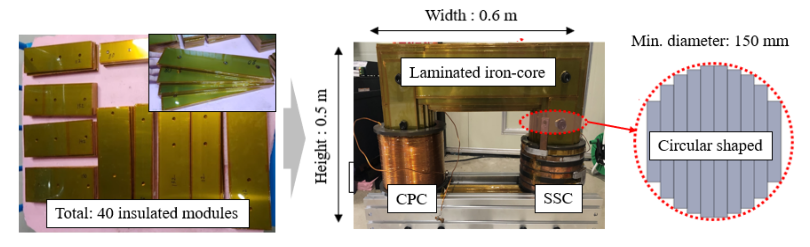
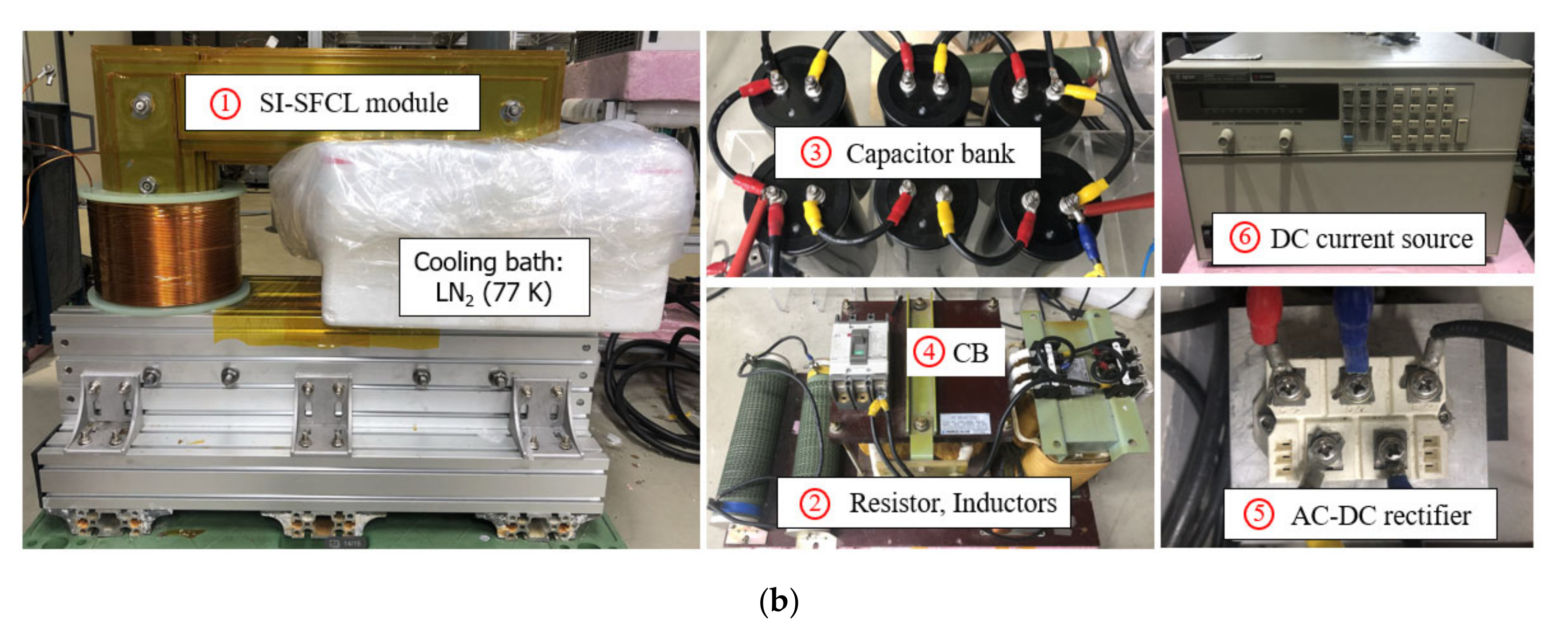
4.1. Fabrication and Pre-Testing of the Lab-Scale SI-SFCL

Figure 10 describes the designed structure and fabrication of the iron-core system for the lab-scale SI-SFCL. The iron-core was designed to minimize the core losses, including the eddy current and hysteresis losses, during the transient fault. Such core losses cause a high reluctance path to the magnetic field and magnetic energy losses, reducing the fault limiting ability of the SI-SFCL. The iron-core constructed from thin silicon steel lamination, which has high permeability, can reduce these unwanted losses. The resistivity of the silicon steel is high, and these steel laminations were insulated from each other by a thin Kapton tape layer, thereby increasing the overall resistance of the iron-core to prevent the flow of the eddy current. The non-oriented silicon steel 50PN470, which can be saturated at 1.6–1.7 T, was chosen for the iron-core design. The circular-shaped core was implemented to reduce the coil area, which, in turn, reduces the wire length and cost of the coil system.
Figure 11a describes the fabrications of the CPCs with the three bobbin types. We used the enameled copper wire for the CPC, and its diameter was 2.8 mm. The height, inner and outer radii of all the designed CPC were 140 mm, 90 mm, and 112 mm, respectively. The CPC was wound on the bobbin with four layers, and the number of turns in each layer was 50. The SSC with three DPCs was wound and fabricated as shown in Figure 11b. Before testing the SI-SFCL under the fault condition, the designed parameters and operating characteristics of the iron-coreless CPC and SSC were first confirmed.
The parameters of the CPC, including resistance and inductance, can be measured by a LCR meter. On principle, the LCR meter supplies an AC current to the coil at a chosen frequency, f, to measure the voltage, current, and phase difference between the voltage and current; and then the coil inductance. This AC current can cause the eddy current loss in the metal bobbins. Thus, we can see the effect of the eddy current loss in the coil inductance by measuring the inductance at different frequencies. We also calculated the resistance and inductance of the CPC at different frequencies in the FEM simulation to compare them with the measured results. Table 5 shows the comparison between the measured and FEM simulation results of the resistances and inductances of the CPC. As a result, the measured results were similar to the calculated results. With the GFRP bobbin, there is no eddy current loss, so the inductance of the CPC did not change with frequency. In the case of using the Al-solid bobbin, the inductance was much lower than that of using the GFRP bobbin, and there was a large difference according to the high frequency. This means that the Al-solid bobbin caused high eddy current losses, which significantly reduced the inductance of the CPC. The Al-cutting bobbin significantly improved this problem, but at higher frequencies the inductance was still reduced. However, it was much higher than with the Al-solid bobbin.
In addition, we confirmed the operating characteristics of the SSC at an operating temperature of 77 K, as shown in Figure 12. The self-inductance and critical current of the SSC are measured to be 4.1 mH and 250 A, respectively. With the operating current of 200 A, the safety margin of the SSC is 20%.

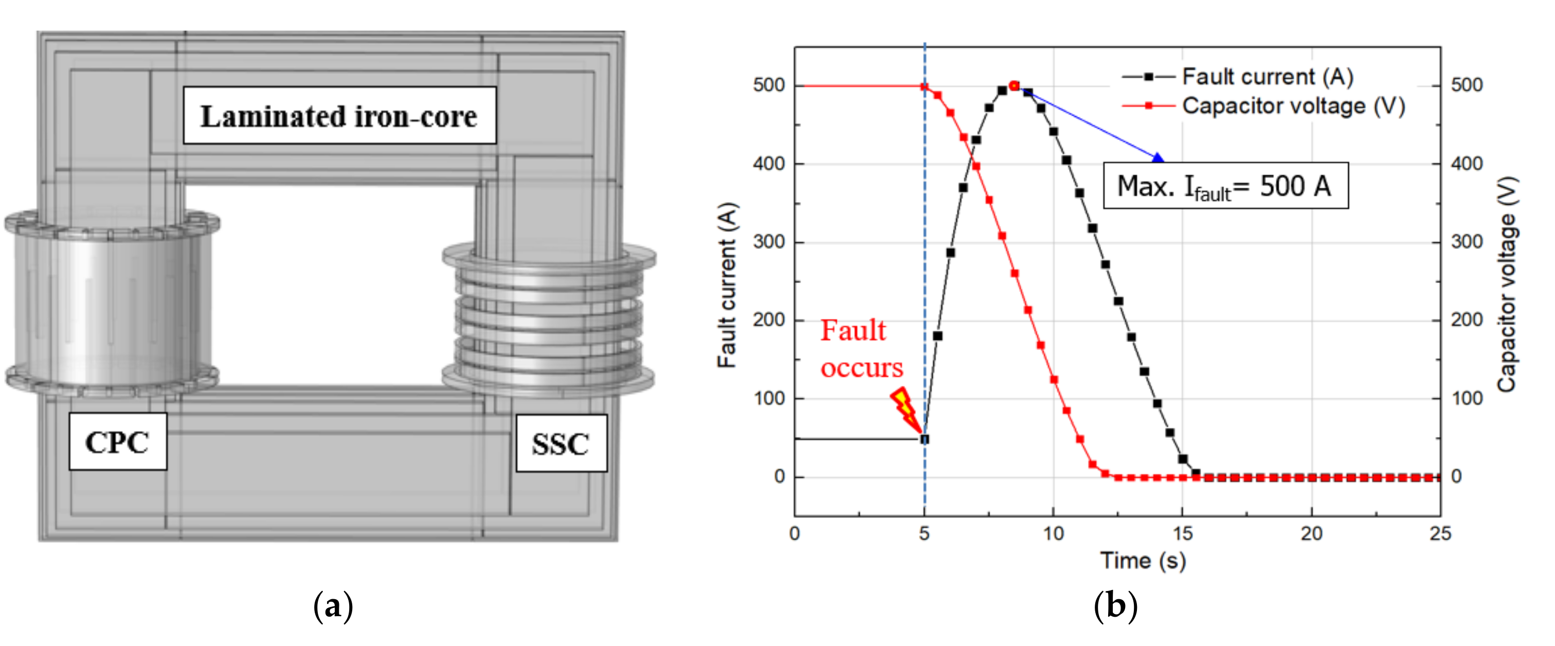
4.2. Experiment Circuit for Testing the DC Fault

Base on the operating principle of the VSC-DC power system, a simplified experiment circuit was developed for the normal operation and fault condition tests of the SI-SFCL, as shown in Figure 13. In a normal operation, the circuit breaker (CB) is in a closed state, and the normal current of 50 A flows through the CPC. The SSC is supplied by the DC current source and generates an opposite magnetic field to that of the CPC. The operation of the SSC was controlled and monitored by the LabView program. When the CB is opened, the DC power system is insulated from the AC side, which leads the capacitor discharge state. The transient process of the capacitor discharging causes the short-circuit fault current. The fault current and capacitor voltage were measured using an Oscilloscope. In the SI-SFCL module, the SSC is located in a cooling bath and cooled by liquid nitrogen (LN2).

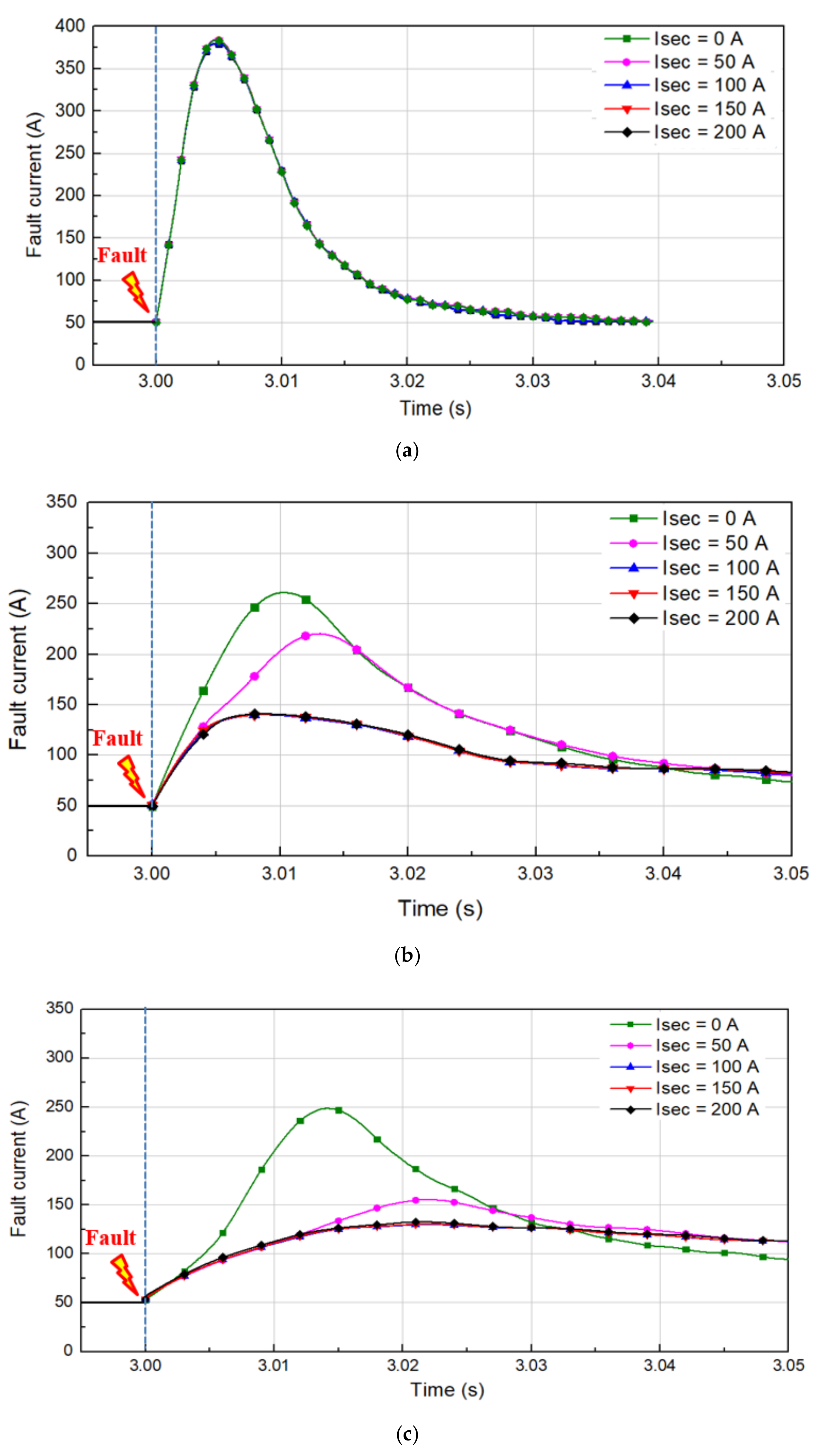
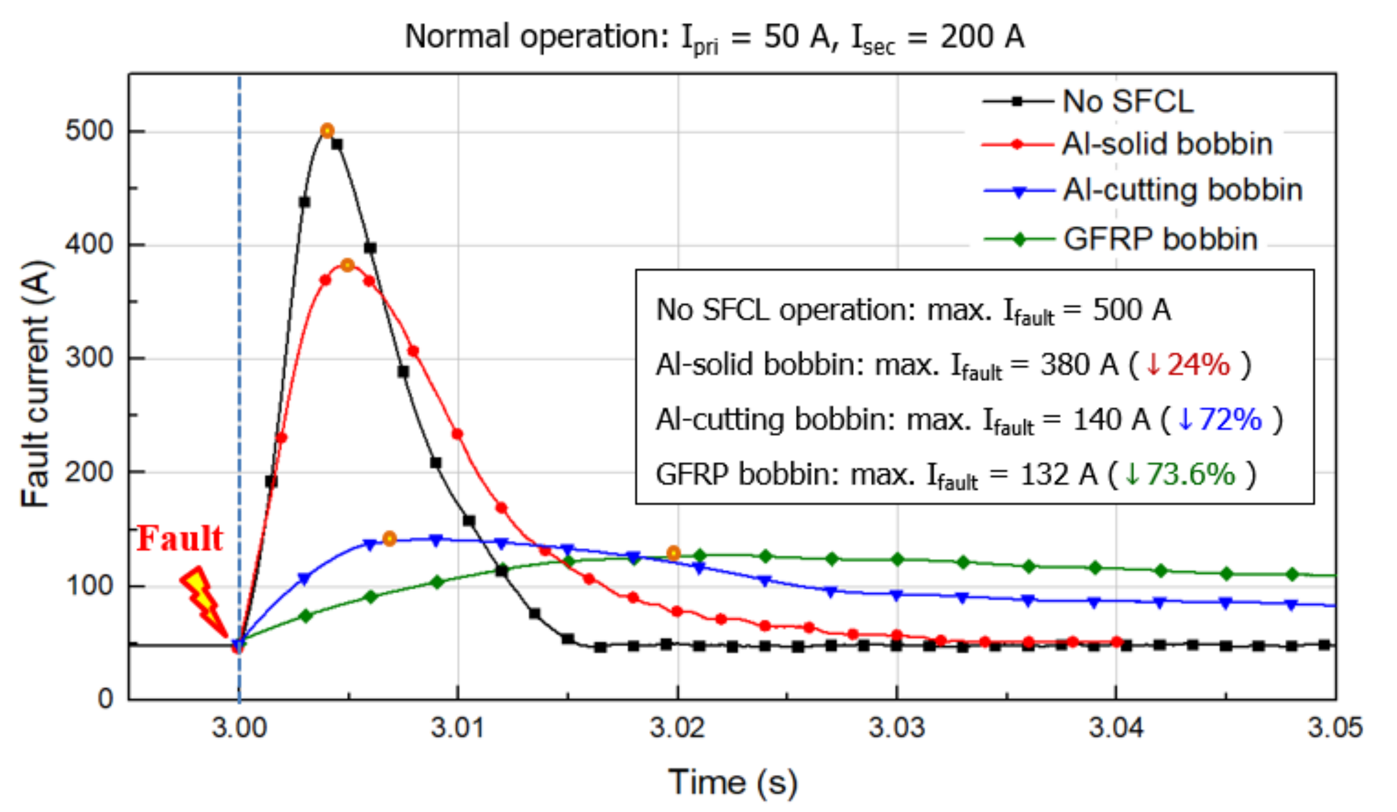
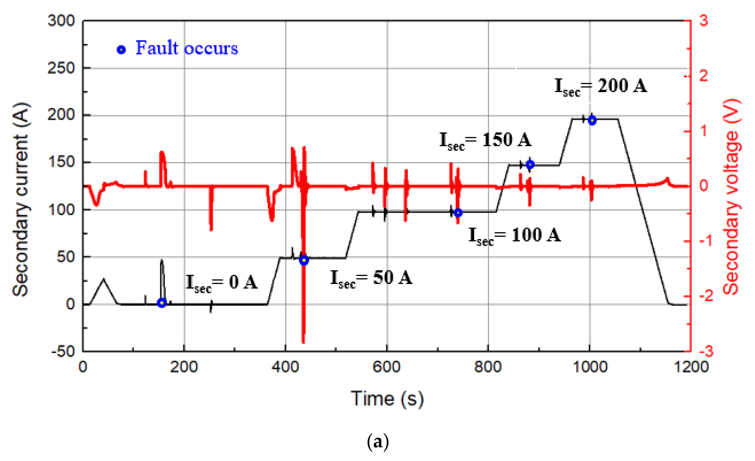
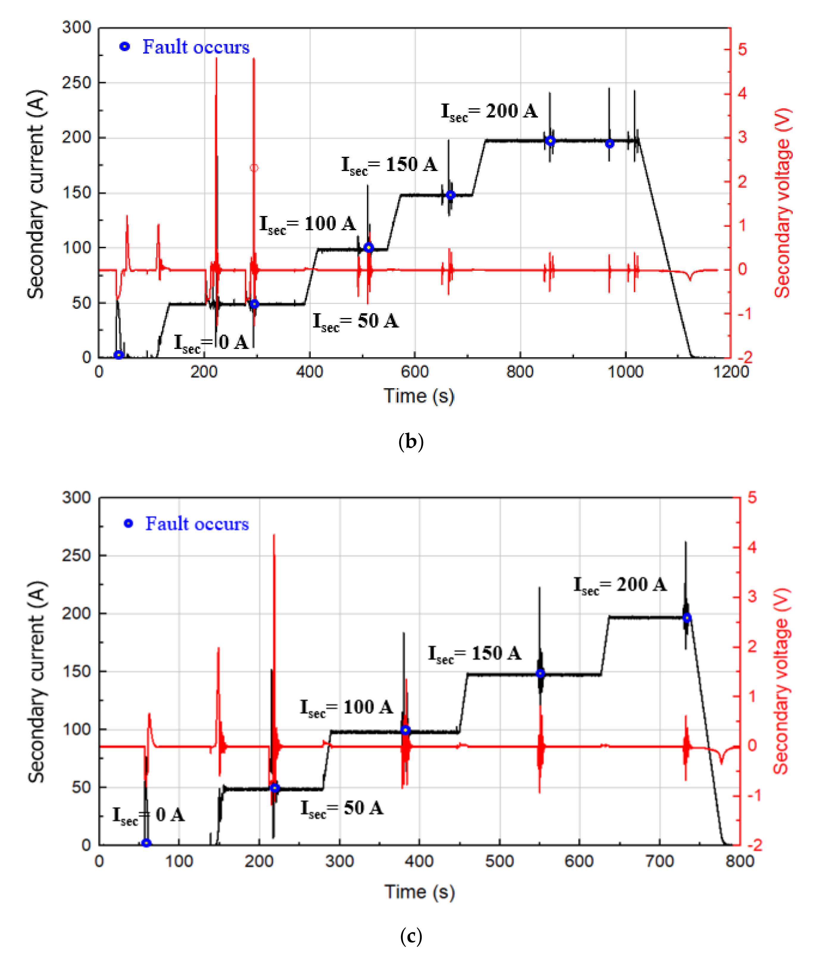
4.3. Performance Analysis of the Lab-Scale SI-SFCL

In the experiment, we tested the SI-SFCL operation under the fault condition with different operating currents of the SSC and three kinds of CPC bobbins, as shown in Figure 14. The operating current of the SSC was increased from 0 A to 200 A, with a step of 50 A. The designed operating current of the SSC was 200 A. In the case of using the Al-solid bobbin, the fault current limits of the SI-SFCL were the same for all operating currents of the SSC as described in Figure 14a. The SI-SFCL only reduced the magnitude of the fault current by 24%. This result was similar to the FEM simulation result, which showed that the high eddy current loss of the Al-solid bobbin significantly reduced the fault current limit ability of the SI-SFCL. In Figure 14b, using the Al-cutting bobbin, the fault current limit showed a great improvement. The SI-SFCL more significantly limited the fault current when increasing the operating current of the SSC. With the SSC current being higher than 100 A, the SI-SFCL decreased the fault current level to 140 A, increasing the limitation rate up to 72%. As a result, the SI-SFCL using the GFRP bobbin in the CPC achieved the highest performance in terms of the fault current limit due to no eddy current loss. The fault current limit rate in this case was 73.6%; however, it was only slightly higher than that of the Al-cutting bobbin.
With the SSC operating current of 200 A, the fault current limits of the SI-SFCL using three kinds of CPC bobbins were compared as shown in Figure 15. Using the GFRP and Al-cutting bobbin in the CPC, the SI-SFCL achieved the design target, which was the fault limitation rate of 70%. However, there was a difference in the rising of the fault current di/dt between them. In the case of using the Al-cutting bobbin, the rising of the fault current was faster than that of the GFRP bobbin, because it still had a small eddy current loss. However, this could be solved by making more cuts on the bobbin. The slower rising of the fault current allows for more time for the DCCB operation.
In addition, the operating characteristics of the SSC during the fault tests were monitored and analyzed. The fault current limit process caused the induced current and voltage in the SSC. If the induced current and voltage are too high, they can damage the SSC and the DC bias source. Figure 16 shows the operating characteristics of the SSC during the fault tests with the three different kinds of CPC bobbins. As a result, the induced currents and voltages in the SSC were quite low in both cases that did not affect the DC bias source and the SSC operation.
The Al-solid bobbin significantly reduced the inductance of the CPC and the fault current limit ability of the SI-SFCL, thus reducing the flux change in the iron-core. Therefore, the induced current and voltage in this case were very small, as shown in Figure 16a. As a result, the GFRP bobbin caused the highest induced current and voltage in the SSC. The detailed measured results of the maximum current and voltage in the SSC with three kinds of CPC bobbins during the fault tests are summarized in Table 6.
Table 7 summarizes and compares the characteristics of the three CPC bobbins applied to the SI-SFCL. As a result, the Al-cutting bobbin showed more advantages than the others. Specifically, it solved the problem of the high eddy current loss in the Al-solid bobbin. The SI-SFCL using the Al-cutting in the CPC not only achieved the same high fault current limit performance as the GFRP bobbin but also reduced the induced current and voltage in the SSC. Further, the Al-cutting bobbin has a much lower material cost when compared to that of the GFRP bobbin.
In addition, we performed a detailed cost analysis of the lab-scale SI-SFCL with the proposed design options of the coil system. Table 8 summarizes the total cost of fabrication of for the lab-scale SI-SFCL, including the iron-core, SSC, CPC, and other costs, such as supports, bolts, Kapton tape, etc. The costs of the SSC and CPC were calculated in for their different design options so that the SI-SFCL can achieve the fault limitation rate of 70%. Thus, the SSC was considered for three kinds of 2G HTS wires (A1, A2, and A3), and the CPC was analyzed with GFRP and Al-cutting bobbins. As a result, the SI-SFCL using the A2 wire in the SSC and the GFRP bobbin in the CPC recorded the highest cost, and the total cost in this case was set at 100% for comparison with the others. As a result of the cost analysis, the SI-SFCL had the lowest total cost when using the A1 wire for the SSC and the Al-cutting bobbin for the CPC. In this case, it significantly reduced the total cost by up to 26.1%. Therefore, from the results of this study, it can be concluded that it brings cost effectiveness to the actual design of the SI-SFCL in a DC power system.
In HVDC power systems, the induced current and voltage in the SSC are very high, which can damage the DC bias source, the SSC, and may affect the fault current limit performance of the SI-SFCL. Thus, protection methods must be carefully considered when designing the SI-SFCL for DC power systems. By applying the Al-cutting bobbin in the CPC and the aluminum bobbin in the SSC, we can reduce the costs and complications associated with the protection design of the SSC. The problem of eddy current loss can also be applied to the optimal design of the iron-core system. This paper only focused on the design options of the coil systems for the SI-SFCL in the DC power system and confirmed them through a physical experiment. Other issues that affect the performance of the SI-SFCL, such as the magnetizing of the iron-core, the transient inductance of the CPC, power losses, and protection methods, will be discussed in future studies.

5. Conclusions

The authors presented an effective solution related to the optimal design for improving the operational performance and economics of a SI-SFCL for DC power systems. Design options for the coil system of the SI-SFCL were proposed, and the operating characteristics and performance of the SI-SFCL were then analyzed through both a simulation and a hardware-based experiment. The 3D FEM model was also built to analyze the operational features and fault current limit of the SI-SFCL with the designed coils. The fault current limitation rate of the lab-scale was targeted at 70%. The coil system of the SI-SFCL included the CPC and SSC. The design of the SSC was based on shape, wire selection, required fault current limit and protection aspects. The 2G HTS wire was selected due to its high performance and high critical temperature. The SuNAM wire was selected to build the SSC at the lowest cost. Turn to turn insulation and bobbin material were considered to protect the SSC from the induced current and voltage during the fault. In the case of the CPC, the bobbin of the CPC was designed based on material selection, cost, structure and the effects on the fault current limit of the SI-SFCL. Three kinds of CPC bobbins—Al-solid, Al-cutting, and GFRP bobbins—were applied. The eddy current loss in the CPC bobbin had a great influence on the fault current limit ability of the SI-SFCL. A lab-scale SI-SFCL was developed and fabricated for testing the operation characteristics on a 500 V, 50 A DC power system. Through the experiment, the operating characteristics of each coil were confirmed. The fault current limits of the SI-SFCL, according to the operating currents of the SSC and bobbin designs of the CPC, were analyzed and compared. As a result, with the CPC using the Al-solid bobbin, the SI-SFCL only limited the magnitude of the fault current level by 24% due to its high eddy current loss. In the case of using the Al-cutting bobbin, the SI-SFCL effectively reduced the rate of increase, as well as the magnitude, of the fault current, with a fault limitation rate of up to 72%, which was similar to that of the GFRP bobbin. The Al-cutting bobbin could also significantly reduce the induced current and voltage in the SSC in order to protect the SSC and DC bias source. Further, the Al-cutting bobbin had a much lower cost than the GFRP bobbin. Through the cost analysis, the high cost-effectiveness for the SI-SFCL with the proposed design options was demonstrated. We are confident that the results of this study can be effectively applied to large-scale SI-SFCL development research on multi-terminal HVDC power systems in the future.

Author Contributions

Conceptualization, methodology, experiment, writing-original draft preparation: V.Q.D.; experiment support: J.-I.L., C.S.K. and U.M.; validation, writing-review and editing: V.Q.D. and C.S.K.; project administration: C.S.K.; supervision: M.P. All authors have read and agreed to the published version of the manuscript.

Funding

This research was supported by Korea Electric Power Corporation [grant number: R16XA01].

Conflicts of Interest

The authors declare no conflict of interest.

References

  1. Rafferty, J.; Morrow, D.J.; Xu, L. Analysis of VSC-based HVDC system under DC faults. In Proceedings of the 39th Annual Conference of the IEEE Industrial Electronics Society IECON 2013, Austria Center Vienna, Vienna, Austria, 10–14 November 2013; pp. 459–464. [Google Scholar] [CrossRef]
  2. Ahmed, W.; Manohar, P. DC line protection for VSC-HVDC system. In Proceedings of the 2012 IEEE International Conference on Power Electronics, Drives and Energy Systems (PEDES), Bangaluru, India, 16–19 December 2012; Institute of Electrical and Electronics Engineers (IEEE): Piscataway, NJ, USA, 2012; pp. 1–6. [Google Scholar] [CrossRef]
  3. Hwang, S.H.; Choi, H.-W.; Jeong, I.-S.; Choi, H.-S. Characteristics of DC Circuit Breaker Applying Transformer-Type Superconducting Fault Current Limiter. IEEE Trans. Appl. Supercond. 2018, 28, 1–5. [Google Scholar] [CrossRef]
  4. Hong, Y.; Yu, T. Reliability Improvement Strategies for HVDC Transmission System. Energy Power Eng. 2013, 5, 52–56. [Google Scholar] [CrossRef]
  5. Tang, L.; Ooi, B.-T. Protection of VSC-multi-terminal HVDC against DC faults. In Proceedings of the 2002 IEEE 33rd Annual IEEE Power Electronics Specialists Conference, Cairns, Qld., Australia, 23–27 June 2002; pp. 719–724. [Google Scholar] [CrossRef]
  6. Rafferty, J.; Xu, L.; Morrow, D.J. DC fault analysis of VSC based multi-terminal HVDC systems. In Proceedings of the 10th IET International Conference on AC and DC Power Transmission (ACDC 2012), Birmingham, UK, 4–5 December 2012; pp. 1–6. [Google Scholar] [CrossRef]
  7. Franck, C.M. HVDC Circuit Breakers: A Review Identifying Future Research Needs. IEEE Trans. Power Deliv. 2011, 26, 998–1007. [Google Scholar] [CrossRef] [Green Version]
  8. Tahata, K.; Ito, H.; Yamamoto, R. HVDC circuit breakers for HVDC grid applications. In Proceedings of the 11th IET International Conference on AC and DC Power Transmission, Birmingham, UK, 10–12 February 2015; p. 044. [Google Scholar] [CrossRef] [Green Version]
  9. Pei, X.; Smith, A.C.; Barnes, M. Superconducting Fault Current Limiters for HVDC Systems. Energy Procedia 2015, 80, 47–55. [Google Scholar] [CrossRef]
  10. Chen, Y.; Liu, X.; Sheng, J.; Cai, L.; Jin, Z.; Gu, J.; An, Z.; Yang, X.; Hong, Z. Design and Application of a Superconducting Fault Current Limiter in DC Systems. IEEE Trans. Appl. Supercond. 2013, 24, 1–5. [Google Scholar] [CrossRef]
  11. Lee, H.-Y.; Asif, M.; Park, K.-H.; Lee, B.-W. Feasible Application Study of Several Types of Superconducting Fault Current Limiters in HVDC Grids. IEEE Trans. Appl. Supercond. 2018, 28, 1–5. [Google Scholar] [CrossRef]
  12. Zhang, L.; Shi, J.; Wang, Z.; Tang, Y.; Yang, Z.; Ren, L.; Yan, S.; Liao, Y. Application of a Novel Superconducting Fault Current Limiter in a VSC-HVDC System. IEEE Trans. Appl. Supercond. 2017, 27, 1–6. [Google Scholar] [CrossRef]
  13. Zhu, J.; Li, Y.; Duan, X. Application of SFCLs to Inhibit Commutation Failure in HVdc Systems: Position Comparison and Resistance Recommendation. Can. J. Electr. Comput. Eng. 2017, 40, 31–40. [Google Scholar]
  14. Xiang, B.; Yang, K.; Tan, Y.; Liu, Z.; Geng, Y.; Wang, J.; Yanabu, S. DC-Current-Limiting Characteristics of YBCO Tapes for DC Currents of 50 A to 10 kA. IEEE Trans. Appl. Supercond. 2017, 27, 1–5. [Google Scholar] [CrossRef]
  15. Yang, Q.; le Blond, S.; Liang, F.; Yuan, W.; Zhang, M.; Li, J. Design and Application of Superconducting Fault Current Limiter in a Multiterminal HVDC System. IEEE Trans. Appl. Supercond. 2017, 27, 1–5. [Google Scholar] [CrossRef] [Green Version]
  16. Morishita, Y.; Ishikawa, T.; Yamaguchi, I.; Okabe, S.; Ueta, G.; Yanabu, S. Applications of DC Breakers and Concepts for Superconducting Fault-Current Limiter for a DC Distribution Network. IEEE Trans. Appl. Supercond. 2009, 19, 3658–3664. [Google Scholar] [CrossRef]
  17. Li, B.; Cui, H.; Jing, F.; Li, B.; Liu, Y. Current-limiting characteristics of saturated iron-core fault current limiters in VSC-HVDC systems based on electromagnetic energy conversion mechanism. J. Mod. Power Syst. Clean Energy 2018, 7, 412–421. [Google Scholar] [CrossRef] [Green Version]
  18. Li, B.T.; Jia, J.F.; Li, B.; Zhang, Y.K. Fault analysis of VSC-HVDC system with saturated iron-core superconductive fault current limiter. In Proceedings of the 2015 IEEE International Conference on Applied Superconductivity and Electromagnetic Devices (ASEMD), Shanghai, China, 20–23 November; pp. 388–390. [CrossRef]
  19. Wang, C.; Li, B.; He, J.; Xin, Y. Design and Application of the SFCL in the Modular Multilevel Converter Based DC System. IEEE Trans. Appl. Supercond. 2017, 27, 1–4. [Google Scholar] [CrossRef]
  20. Li, B.; Jing, F.; Jia, J.; Li, B. Research on Saturated Iron-Core Superconductive Fault Current Limiters Applied in VSC-HVDC Systems. IEEE Trans. Appl. Supercond. 2016, 26, 1–5. [Google Scholar] [CrossRef]
  21. Li, B.; Jing, F.; Li, B.; Chen, X.; Jia, J. Study of the Application of Active Saturated Iron-Core Superconductive Fault Current Limiters in the VSC-HVDC System. IEEE Trans. Appl. Supercond. 2018, 28, 1–6. [Google Scholar] [CrossRef]
  22. Xin, Y.; Gong, W.Z.; Gao, Y.Q.; Niu, X.Y.; Guo, Q.Q. Introduction of 35 kV/90 MVA saturated iron-core superconducting fault current limiter. Rare Met. Mater. Eng. 2008, 37, 275–280. [Google Scholar]
  23. Gong, W.; Zhang, J.; Cao, Z.; Hong, H.; Tian, B.; Wang, Y.; Wang, J.; Niu, X.; Qiu, J.; Wang, S.; et al. HTS dc bias coil for 35kV/90MVA saturated iron-core fault current limiter. Phys. C Supercond. 2008, 468, 2050–2053. [Google Scholar] [CrossRef]
  24. Pellecchia, A.; Klaus, D.; Masullo, G.; Marabotto, R.; Morandi, A.; Fabbri, M.; Goodhand, C.; Helm, J.; Antonio, P. Development of a Saturated Core Fault Current Limiter with Open Magnetic Cores and Magnesium Diboride Saturating Coils. IEEE Trans. Appl. Supercond. 2016, 27, 1. [Google Scholar] [CrossRef]
  25. Moriconi, F.; de la Rosa, F.; Darmann, F.; Nelson, A.; Masur, L. Development and Deployment of Saturated-Core Fault Current Limiters in Distribution and Transmission Substations. IEEE Trans. Appl. Supercond. 2011, 21, 1288–1293. [Google Scholar] [CrossRef]
  26. Yang, J.; Fletcher, J.E.; O’Reilly, J. Short-Circuit and Ground Fault Analyses and Location in VSC-Based DC Network Cables. IEEE Trans. Ind. Electron. 2012, 59, 3827–3837. [Google Scholar] [CrossRef] [Green Version]
  27. Dao, V.Q.; Lee, J.; Kim, C.-S.; Park, M. Conceptual Design of a Saturated Iron-Core Superconducting Fault Current Limiter for a DC Power System. IEEE Trans. Appl. Supercond. 2020, 30, 1–5. [Google Scholar] [CrossRef]
Figure 1. Equivalent circuit of a resistive type superconducting fault current limiter (R-SFCL) in direct current (DC) power system.
Energies 13 06090 g001
Figure 2. Equivalent circuit of a saturated iron-core SFCL (SI-SFCL) in DC power system.
Energies 13 06090 g002
Figure 3. Equivalent circuit of the voltage source converter (VSC)-DC power system with SI-SFCLs.
Energies 13 06090 g003
Figure 4. Designed structure of the SI-SFCL for a DC power system.
Energies 13 06090 g004
Figure 5. Estimation of the critical current in the SSC with three kinds of 2G-HTS wires.
Energies 13 06090 g005
Figure 6. Detailed structure design of the SSC.
Energies 13 06090 g006
Figure 7. Two configurations of the bobbin for the CPC: (a) Solid bobbin; and (b) Cutting bobbin.
Energies 13 06090 g007
Figure 8. 3D FEM simulation model of the SI-SFCL: (a) 3D graphic model; and (b) Fault current without SFCL operation.
Energies 13 06090 g008
Figure 9. Fault current limit characteristics of the SI-SFCL using three kinds of CPC bobbins in the FEM simulation: (a) Eddy current loss; and (b) Fault current limit of the SI-SFCL.
Energies 13 06090 g009
Figure 10. Structure design and fabrication of the iron-core system for the SI-SFCL.
Energies 13 06090 g010
Figure 11. Fabrications of the coil system for the SI-SFCL: (a) The conductive primary coil (CPC) with three bobbin types; and (b) the SSC using A1 wire (SuNAM).
Energies 13 06090 g011aEnergies 13 06090 g011b
Figure 12. Estimation of the critical current of the SSC cooled by liquid nitrogen (LN2).
Energies 13 06090 g012
Figure 13. Experiment circuit for the performance test of the lab-scale SI-SFCL: (a) Equivalent circuit of the fault current testing; and (b) equipment of the testing system.
Energies 13 06090 g013aEnergies 13 06090 g013b
Figure 14. Fault current limit characteristics of the SI-SFCL according to the SSC currents in three kinds of CPC bobbins: (a) solid aluminum (Al-solid) bobbin; (b) cutting aluminum (Al-cutting) bobbin; and (c) glass fiber reinforced polymer (GFRP) bobbin.
Energies 13 06090 g014
Figure 15. Comparison of the fault current limit of the SI-SFCL in three kinds of CPC bobbin (Isec = 200 A).
Energies 13 06090 g015
Figure 16. Operating characteristics of the SSC under the fault condition in three cases of CPC bobbin: (a) Al-solid bobbin; (b) Al-cutting bobbin; and (c) GFRP bobbin.
Energies 13 06090 g016aEnergies 13 06090 g016b
Table 1. Designed specifications of the lab-scale SI-SFCL in the 500 V, 50 A DC power system.
ItemsValues
Normal voltage of DC system, Vc500 V
Normal current of DC system, Ic50 A
Rated power of DC system, Pm25 kW
DC line resistance, Rc0.5 Ω
DC line inductance, Lc1.651 mH
Capacitor bank, C5300 µF
Fault current without the SI-SFCL500 A
Target of fault limitation rate>70%
Core material50PN470
Saturated magnetic field of the iron-core, Bmax1.7 T
Cross-section area of the iron-core, Acore0.01 m2
Length of the magnetic path in the iron-core, lcore1.6 m
Number of turns in the CPC, Npri198 turns
Air-core inductance of the CPC, Lpri6 mH
Table 2. Specifications of three kinds of second-generation high-temperature superconducting (2G HTS) wires using for the superconducting secondary coil (SSC).
ItemsA1A2A3
Wire shapeLaminated tapeLaminatedLaminated tape
Dimension (width × thickness)12.1 mm × 0.22 mm12 mm × 0.23 mm10 mm × 0.15 mm
Critical bend radius30 mm30 mm60 mm
Critical ten. strength550 MPa300 MPa250 MPa
Critical current at 77 K, 0 T600 A500 A380 A
Wire cost (%)59.6%100%55%
Table 3. Detailed specifications of the SSCs using three kinds of 2G HTS wires.
ItemsA1A2A3
Fault current without the SI-SFCL500 A
Fault limitation rate70% (Ifault = 150 A)
Number of turns of the CPC198 turns
Number of turns of the SSC150 turns135 turns170 turns
Coil shapeCircular coilCircular coilCircular coil
Inner radius of the SSC92 mm92 mm92 mm
Self-inductance4.8 mH4.3 mH5.2 mH
Critical current at 77 K, 0 T, Ic255 A278 A230 A
Operating current at 77 K, Iop200 A220 A185 A
Safe margin of the operating current21.5%20.8%20.6%
Total wire length88.7 m82.4 m98 m
Total wire cost64.1%100%65.4%
Table 4. Comparison of three kinds of CPC bobbins.
ItemsAl-SoildAl-CuttingGFRP
MaterialsAl-6061Al-6061GFRP
Dimension (inner radius × height)80 mm × 158 mm80 mm × 158 mm80 mm × 158 mm
Maximum eddy current loss37 kW10.6 kW0 kW
Fault limitation rate of the SI-SFCL33%69%75%
Table 5. Comparison between the measured and finite element method (FEM) simulation results of the CPC parameters.
ItemsAl-SolidAl-CuttingGFRP
FEMMeasuredFEMMeasuredFEMMeasured
Resistance (Ω)0.390.40.390.40.390.4
Air-core inductance
(m H)
f = 100 Hz1.3071.2705.0635.0225.9986.057
f = 120 Hz1.2241.2194.8354.8995.9986.049
f = 1000 Hz0.0810.8663.1243.2595.9986.035
f = 10,000 Hz0.3750.3812.1862.3615.9986.000
Table 6. Maximum currents and voltages in the SSC with three kinds of CPC bobbins during the fault.
SSC Operating CurrentsAl-Solid BobbinAl-Cutting BobbinGFRP Bobbin
Max. IsecMax. VsecMax. IsecMax. VsecMax. IsecMax. Vsec
Isec = 0 A47 A0.65 V53 A0.7 V76 A0.84 V
Isec = 50 A78 A2.83 V186 A4.83 V156 A4.2 V
Isec = 100 A108 A0.62 V157 A0.86 V184 A2.2 V
Isec = 150 A155 A0.35 V199 A0.55 V223 A0.82 V
Isec = 200 A202 A0.24 V245 A0.49 V262 A0.7 V
Table 7. Summary of characteristic and performance of the SI-SFCL with three kinds of CPC bobbin.
ItemsAl-SolidAl-CuttingGFRP
MaterialsAl-6061Al-6061GFRP
Dimension (inner radius x height)80 mm × 158 mm80 mm × 158 mm80 mm × 158 mm
Fault current without the SI-SFCLIfault = 500 A
Max. eddy current loss (FEM)37 kW10.6 kW0 kW
Fault limitation rate (FEM)33%69%75%
Fault limitation rate in experiment24%72%73.6%
Induced current in the SSC
(Isec = 200 A)
202 A245 A262 A
Induced voltage in the SSC
(Isec = 200 A)
0.24 V0.45 V0.7 V
Material cost (%)33%33%100%
Table 8. Summary of the total cost for the SI-SFCL with different design options for the coil system.
CasesIron-CoreSSCCPCOthersTotal Cost (%)
A1 WireA2 WireA3 WireGFRPAl-Cutting
133.7-53.6-10.2-2.5100
2-53.6--3.486.4
3--35.110.2-81.5
4--35.1-3.474.7
534.3--10.2-80.7
634.3---3.473.9
Publisher’s Note: MDPI stays neutral with regard to jurisdictional claims in published maps and institutional affiliations.

