Abstract
A review on the rotating stall in the vaneless diffuser of centrifugal compressors is presented showing that different stall modes characterized by different numbers of cells can be detected within the diffuser even if the operating condition remains unchanged. The interaction between the inlet perturbation and the stall cells near the diffuser outlet is supposed to be the trigger of the stall mode transformation. In order to determine if the inlet perturbation will interact with the downstream stall cells, a characteristic time analysis is proposed to estimate the characteristic time of the perturbation in radial and tangential directions. An additional theoretical model which focused on the development of the vaneless diffuser rotating stall is presented to determine the propagation velocity of the cells. The comparison between the characteristic time in two directions shows that one stall mode is able to evolve into another stall mode if a critical condition is met, and the stall mode transformation is more likely to start from a mode with a higher number of cells and is more likely to occur in the diffuser with a large radius ratio. Experimental results are also employed to validate the proposed critical condition, and good agreements are obtained.
1. Introduction
Turbomachinery is undoubtedly important for modern industrialized society, especially in the fields of small and medium-sized aero-engines, refrigeration, chemical factory, vehicles, etc. [1,2,3,4,5]. As power machinery, a wide, high-efficiency operating range is required for compressors, considering not only the efficiency but also the stability and safety [6,7,8]. However, the behaviors of compressor operating under off-design conditions are subject to various unstable phenomena which could have negative effects on their performance and then lead to further increased losses and energy consumption. Therefore, instabilities in the compressor are an interesting topic for scholars. For example, Ceyrowsky et al. [9] studied the influence of a volute in the triggering of the instability phenomenon by means of one dimensional analysis and CFD (Computational Fluid Dynamics). The volute, designed according to conservation of angular momentum, generates inhomogeneous static pressure distribution even under nominal conditions. It has been further analyzed how a pressure distortion propagates from a diffuser outlet to the impeller. Carretta et al. [10] adopted a stability parameter (SP) to predict the stability limit; the contribution of each component to the compressor stability was specifically analyzed, and the results showed that the vaned diffuser was responsible for the compressor instability. Bardelli et al [11] investigated the flow in the centrifugal stage of a compressor by different CFD models; unsteady phenomena captured by steady and unsteady simulations have been carefully compared with experimental data in the available literature. Among the instabilities in compressors, one unsteady flow phenomenon, which is known as a rotating stall, has been reported in both centrifugal [12,13,14] and axial [15,16,17,18] compressors. Moreover, a rotating stall can also be detected in different components even in the same system [19,20,21]. The conventional rotating stall occurs when the incidence angle reaches a critical value; part of the fluid cannot follow the main streamline due to the pressure gradient and is then shed from the solid surface; consequently, the local passage then stalls. The stalled region is characterized by reduced or no through flow, which results in the deterioration of the system performance, and even drives the system to become more unstable (for example, a surge).
The present study is focused on a rotating stall in the wide vaneless diffuser of a centrifugal compressor. A vaneless diffuser is composed of two parallel walls and is placed downstream of the centrifugal impeller (as illustrated in Figure 1). It is used to collect the highly distorted flow discharged from the impeller outlet, and is able to transform part of the initial kinetic energy into static pressure rise due to the increasing flow area along the radius. A well-designed diffuser decreases the flow instabilities coming from the impeller outlet, as well as energy losses. However, under off-design conditions, the flow field within the vaneless diffuser could be stalled due to boundary layer separation or core flow instability; the mechanisms and characteristics of this type of rotating stall have been extensively studied, theoretically [22,23,24,25], experimentally [26,27,28,29,30,31,32], and numerically [33,34,35,36,37,38,39].

Figure 1.
Sketch of a centrifugal compressor.
The topology of rotating stall cells in the vaneless diffuser is shown in Figure 2, the characteristics of which can be briefly summarized as follows:

Figure 2.
Topology of rotating stall cells in the vaneless diffuser.
- 1)
- A vaneless diffuser rotating stall is composed of several rotating cells ; the cells propagate circumferentially around the diffuser.
- 2)
- The circumferential propagation velocity of the stall cells is a fraction of the impeller speed.
- 3)
- Each cell is formed by both inward and outward radial velocity components. Therefore, the reverse flow regions will block the flow passages and result in the deterioration of the diffuser performance.
In Figure 2, a stall pattern with four rotating cells is illustrated as an example. However, in previous experimental studies [40,41], the authors found that the number of stall cells is variable even if the operating condition remains unchanged. If a rotating stall with a certain number of cells (n) is defined as one stall mode, the transformation between several stall modes for a given condition does exist in the vaneless diffuser; this phenomenon can also be shown by experimental data reported in related open literature. For example, Abdelhamid and Bertrand [27] experimentally studied a rotating stall in several diffuser configurations (different diffuser radius ratio R and width ratio W) for a constant impeller rotational speed of 5000 r/min; the identified stall modes are listed in Table 1.

Table 1.
Stall modes reported in Abdelhamid and Bertrand [27].
For each configuration, it can be seen that more than one stall mode was identified and the operating condition remained the same. The experimental results presented by Tsujimoto et al [42] showed that two stall modes n = 2 and 3 coexist for diffuser configurations: R = 2.5 operating at 7.5° < α < 16°, R = 2 operating at 7.5° < α < 10.5°, and R = 1.5 operating at 0° < α < 6.5°. Abidogun and Ahmed [43] found two and three cell stall modes at both the stall onset (ϕ = 0.141) and at a lower flow rate condition (ϕ = 0.037). Heng et al [41] experimentally found that several stall modes exist intermittently in a vaneless diffuser under several operating conditions. These results clearly indicated the presence of multi stall modes in the vaneless diffuser under the same operating condition. According to the spectrum analysis in reference [41], the amplitude of the pressure fluctuation due to the interaction between different stall modes is at a significant level and even stronger than the blade passing frequency.
Although alternating stall modes have been reported in many studies, there was no consideration of the mechanism of stall mode transformation. In order to understand how one stall mode evolves into another, the stall inception was carefully analyzed, and then the mechanism of stall mode transformation was proposed. A dedicated characteristic time analysis was compared to determine the critical condition of the mode transformation, and a theoretical model of a vaneless diffuser rotating stall was developed in order to solve the critical condition. The results have been carefully analyzed and compared to the experimental data, and some conclusions were drawn.
2. Discussion of Stall Mode Transformation
Figure 3 is the result obtained by Ljevar [34], who proved that a vaneless diffuser rotating stall can be triggered by the core flow instability due to the interaction between the prescribed inlet jet-wake flow pattern and the vortices at the diffuser outlet. It can be seen that the velocity field under stable conditions is characterized by counterclockwise vortices associated with the prescribed jet-wake flow pattern. With the decrease of the flow angle, the inlet jet-wakes become more circumferential and then interact with the outlet vortices. Consequently, small vortices disappear and large vortex structures (i.e. stall cells) are formed; the vaneless diffuser then operates under the stall condition. In this process, it should be noticed that the number of vortex regions varies from 14 to 7 if the jet-wake flow pattern acts as the inlet perturbation, and one can still regard the stall cells as the downstream large vortex; in a similar process, one existing stall mode can evolve into another if the inlet perturbation is able to interact with the downstream stall cells.

Figure 3.
Velocity vectors in the vaneless diffuser under stable and stalled conditions (extracted from Ljevar [34]): (a) Stable condition; (b) Stalled condition.
In Figure 4, the temporal 2D numerical results presented by Dazin et al [30] further demonstrated the possibility of the interaction. One can notice that the vortex/perturbation created near the diffuser inlet is able to be transported to the diffuser outlet. Since rotating stall cells in the vaneless diffuser are generally located near the outlet and propagate in the circumferential direction, this inlet vortex/perturbation can interact with the downstream stall cells, which is a similar process to the one reported by Lejvar [34]. Therefore, the interaction between the inlet perturbation and propagating stall cells is supposed to be the trigger of the stall mode transformation, and a dedicated characteristics time analysis which was used to determine the critical condition of this interaction is proposed in the next section.

Figure 4.
Transportation of the inlet vortex (extracted from Dazin et al [30]): (a) t/tref = 65.7; (b) t/tref = 66.9; (c) t/tref = 68.1.
3. Characteristic Time Analysis
Table 2 shows the propagation velocity of rotating cells extracted from relevant literature: it can be seen that the propagation velocity of the stall cell Vp is a fraction of the circumferential velocity of the core flow Vθ2. If the perturbation is assumed to be transported by the core flow with Vθ2, then the slower downstream stall cells are able to interact with the faster inlet perturbation if the time needed for this perturbation to catch the stall cells in the circumferential direction is shorter than the time needed for this perturbation to flow out of the vaneless diffuser in the radial direction.
Table 2.
Propagation velocity of rotating stall cells (extracted from available literature).
The inlet perturbation and stall cell are illustrated in Figure 5 where important variables are defined. Although Vr decreases with increasing radius, the order of the magnitude will not change too much. Consequently, the characteristic time needed for this perturbation to flow out of the vaneless diffuser is estimated as follows:
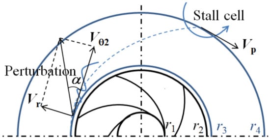
Figure 5.
Illustration of the inlet perturbation and stall cell in the vaneless diffuser (Vr: radial velocity; Vθ2: tangential velocity; r1 and r2: impeller inlet and outlet radii; r3 and r4: diffuser inlet and outlet radii).
In the tangential direction, the order of the magnitude of the characteristic time needed for this perturbation to interact with the downstream stall cells is:
Since the propagation velocity of the stall cells is proportional to the tangential velocity of the core flow, one can define the propagation velocity coefficient as:
then Equation (2) becomes:
As mentioned, the interaction will occur if tθ < tr, which leads to the following critical condition:
where α is the flow angle in the vaneless diffuser, tan α = Vr/Vθ2; R is the diffuser radius ratio, R = r4/r3. In order to solve the critical condition, additional theoretical analysis is presented in the next section to estimate the velocity coefficient k.
4. Analysis of the Propagation Velocity Coefficient k
Since the present study focused on a rotating stall in the “wide” vaneless diffuser, which is considered to be caused by a so-called two dimensional core flow instability instead of the boundary layer separation, more details of the mechanism of this stall inception can be seen in Lejvar [34]. Therefore, the first assumption of the two-dimensional flow in the vaneless diffuser is proposed. Additionally, the fluid is assumed to be incompressible and inviscid, and uniform pressure distribution at the diffuser outlet and prescribed velocity distribution at the diffuser inlet are adopted as the boundary conditions.
Based on the above assumptions, the non-dimensional governing equations, including the continuity equation, Euler equations and vorticity equations for the two-dimensional vaneless diffuser flow are:
where is the swirl which used to represent the vorticity in the present model.
One can notice that the steady solutions for the above equations are:
where Γ is the circulation of the upstream impeller and defines μ = Γ/Q, which is also equal to 1/tan α; notice r = 1 represents the diffuser inlet, and r = R denotes the diffuser outlet.
Since the rotating stall is associated with the two-dimensional core flow instability in the wide vaneless diffuser, and the classical stability analysis assumes that the unsteady flow field can be treated as the superposition of the steady flow and a small unsteady flow, then the unsteady flow is added to the steady solutions as follows:
where ε is a very small constant, .
The unsteady variables in the normal mode can be written as follows:
where n could represent the number of stall cells in the present case; ω = ωreal − iσ , the real and imaginary parts represent the angular frequency and growth rate of the instability, respectively. By substituting Equation (11) and Equation (12) into Equations (6–10), the governing equations of the unsteady flow field are as follows:
Equation set (13–17) is solvable with the following boundary conditions:
Equation (15) can be simplified by Equation (17) if r = R; then the dispersion equation is obtained,
If the two parameters R and n are specified, the angular frequency ωreal is solvable, and then the needed non-dimensional propagation velocity coefficient k is:
5. Results Analysis
5.1. Analysis of Theoretical Results
Based on the above theoretical analysis, one can easily verify the critical condition proposed in Equation (5) when the parameters (n, R) are specified. More generally, the critical condition actually indicated that the inlet perturbation can interact with the downstream stall cells if the flow angle is lower than a critical value associated with the diffuser radius ratio R, number of stall cells n, and the propagation velocity coefficient k; the number of stall cells could be changed, i.e. another stall mode can be expected if the critical condition is satisfied. In addition, one can imagine that stall mode transformation is more likely to happen when the flow angle is small due to two reasons:
- 1)
- A smaller radial velocity increases the time needed for the perturbation to flow out of the vaneless diffuser; then, the perturbation has sufficient time to interact with the stall cells in a circumferential direction;
- 2)
- On the other hand, the interaction is more likely to happen when the inlet perturbation propagates with faster circumferential velocity.
With the given parameters (n, R), the calculated left- and right-hand sides of Equation (5) are compared in Figure 6, and the following conclusions can be drawn:
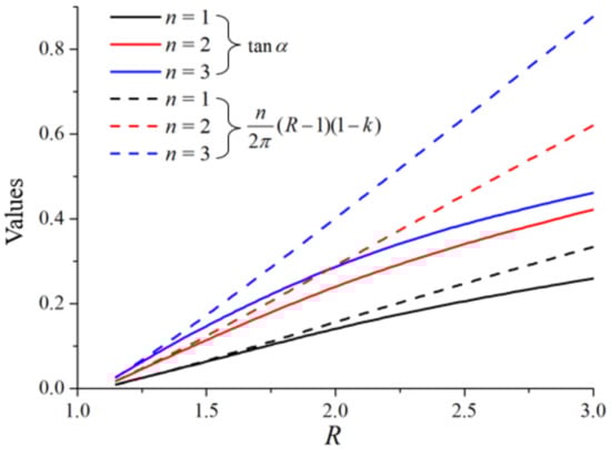
Figure 6.
Theoretical comparison of the left- and right-hand sides of Equation (5).
- 1)
- If the number of stall cells is fixed, one can notice that the difference between the left- and right-hand sides increases with the increase in the diffuser radius ratio, which indicates that the stall mode transformation is more likely to happen when the diffuser radius ratio is large because the inlet perturbation will take more time to flow out of the vaneless diffuser.
- 2)
- For a given diffuser radius ratio, the difference is larger for the stall mode with more cells, which implies that the stall mode transformation is more likely to start from the stall mode with more cells because the circumferential distance between the perturbation and cells is closer, and then the time needed for the inlet perturbation to interact with the cells becomes shorter.
5.2. Experimental Validation
In order to identify the stall modes in a real vaneless diffuser, the experiments were carried out on a centrifugal impeller which was coupled with a vaneless diffuser (R = 1.5), as shown in Figure 7. The main geometrical parameters are listed in Table 3. Since the uniform outlet pressure was assumed in the previous theoretical analysis, the downstream of the vaneless diffuser was connected directly to the atmosphere instead of a volute. The experiment was done in air, the rotating stall was triggered by decreasing the flow rate. Two condenser microphones were installed on the vaneless diffuser at the same radius but with an angular difference of ∆θ = 75°, and then the number of stall cells was obtained based on this angular difference and the measured frequencies of stall modes; more details of the experimental set-up and data manipulation can be seen in Heng et al [41]. All the detected stall modes for each flow condition are listed in Table 4.
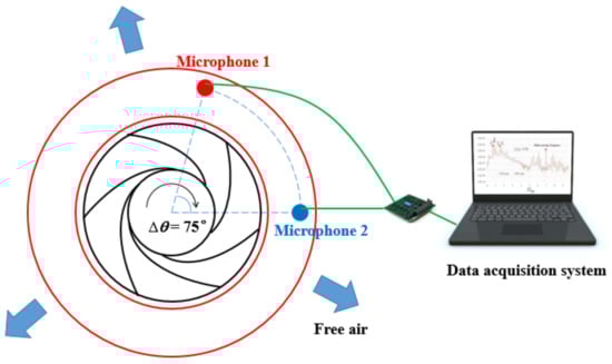
Figure 7.
Experimental testing system.
Table 3.
Geometrical parameters of the centrifugal impeller and vaneless diffuser.
Table 4.
Identified stall modes in the experiments.
In Figure 8, experimental data were applied to validate the critical condition proposed in the present study; the black line represents the left side of Equation (5).

Figure 8.
Experimental validation of the critical condition.
Due to the blockage generated by downstream rotating stall cells, the radial velocity component has been appropriately corrected based on the topology of stall cells shown in the previous PIV results presented by Dazin et al [31]. The Stodola slip coefficient σS was applied in order to calibrate the circumferential velocity Vθ2,
By doing that, the circumferential velocity Vθ2 is:
For the right-hand side of Equation (5), the number and propagation velocity of cells (n, k) and the diffuser radius ratio R are now consistent with the experimental data. According to the comparison in Figure 8, one can notice that:
- 1)
- At flow condition Q/Qd = 0.56 and 0.58, the left side “tan α” of Equation (5) is higher than the right side, which means the critical condition is not met for these two flow conditions. In correspondance, only a stall mode n = 4 was detected in experiments ; the stall mode transformation was not observed in the vaneless diffuser.
- 2)
- At Q/Qd = 0.47, 0.36 and 0.26, the critical condition is always met for one or more stall modes. For such a condition, the stall mode is not stable anymore, and stall transformation is possible. As a consequence, more than one stall mode would be detected. According to Table 4, it can be seen that the identified stall modes in experiments obviously show good agreement with this prediction.
6. Conclusions
Through an investigation of the vaneless diffuser rotating stall, it has been found that the stall mode alternates even if the operating condition remains the same. Data in the literature have been extracted and it has been shown that the propagation velocity of stall cells is a fraction of the core flow. Therefore, the inlet perturbation, which is transported with the core flow, can interact with the downstream cells, resulting in stall mode transformation.
The characteristic time analysis, which focused on the characteristic time in radial and tangential directions, is then proposed to determine the critical condition of this interaction. The radial characteristic time is the time needed for the perturbation to flow out of the vaneless diffuser, and the tangential one is the time needed for the perturbation to interact with the cells. The critical condition of the interaction is obtained by comparing the characteristic time in two directions. In order to solve the critical condition, an additional theoretical model has been presented to estimate the propagation velocity of cells. The calculated results have shown that the stall mode transformation is more likely to happen under the following conditions:
- 1)
- The flow angle is small,
- 2)
- The diffuser radius ratio is large,
- 3)
- Stall mode with more cells.
Experimental results have also been applied to validate the proposed critical condition; it has been found that:
- 1)
- When the critical condition is not met, only one stall mode was identified in the experiments, and no transformation of the stall mode can be observed.
- 2)
- When the critical condition is met, several stall modes were identified in the experiments, and the transformation of stall modes was confirmed.
The above comparison shows good agreement between experimental results and the prediction made by the proposed critical condition.
Author Contributions
Writing—original draft preparation, Y.H.; writing—review and editing, Y.H. and B.H.; experimental measurements, Y.H.; funding acquisition, Q.J., Z.W. and X.L. All authors have read and agreed to the published version of the manuscript.
Funding
This research was funded by the National Key R&D Program of China (2018YFB0905200), National Natural Science Foundation of China (51769035), and “Young Scholars” program of Xihua University (Z202042).
Acknowledgments
The authors acknowledge the financial support from the National Key R&D Program of China (2018YFB0905200), National Natural Science Foundation of China (51769035), and “Young Scholars” program of Xihua University (Z202042).
Conflicts of Interest
The authors declare no conflict of interest.
Nomenclature
| r | radius (m) |
| b | diffuser width (m) |
| t | time (s) |
| u, V | velocity (m/s) |
| U | impeller tip speed (m/s) |
| p, P | pressure (Pa) |
| k | dimensionless propagation velocity (-) |
| i | imaginary unit (-) |
| n | number of stall cells (-) |
| N | rotational speed (rpm) |
| Z | number of blades |
| Greek symbols | |
| ζ | curl (-) |
| ε | minimal value (-) |
| α | flow angle in the vaneless diffuser (°) |
| ω | angular frequency (-) |
| σ | growth rate of mode (-) |
| σS | Stodola slip coefficient (-) |
| ϕ | flow coefficient, (-) ϕ = Vr/Vimp |
| ψ | pressure coefficient,(-) ψ = P/(0.5ρr22ωimp2) |
| R | diffuser radius ratio, (-) R = r4/r3 |
| W | diffuser width ratio, (-) W = b/r3 |
| Q, Qd | flow rate and design flow rate (m3/s) |
| Γ | circulation from impeller outlet (-) |
| Subscripts | |
| 1 | impeller inlet |
| 2 | impeller outlet |
| 3 | diffuser inlet |
| 4 | diffuser outlet |
| r | radial |
| θ | tangential |
| P | propagation |
| B | basic solution |
| imp | impeller |
| Superscripts | |
| ~ | perturbed quantities |
References
- Xue, X.; Wang, T. Stall recognition for centrifugal compressors during speed transients. Appl. Therm. Eng. 2019, 153, 104–112. [Google Scholar] [CrossRef]
- Zhao, B.; Sun, H.; Wang, L.; Song, M. Impact of inlet distortion on turbocharger compressor stage performance. Appl. Therm. Eng. 2017, 124, 393–402. [Google Scholar] [CrossRef]
- Ma, S.B.; Afzal, A.; Kim, K.Y. Optimization of ring cavity in a centrifugal compressor based on comparative analysis of optimization algorithms. Appl. Therm. Eng. 2018, 138, 633–647. [Google Scholar] [CrossRef]
- Galindo, J.; Gil, A.; Navarro, R.; Tarí, D. Analysis of the impact of the geometry on the performance of an automotive centrifugal compressor using CFD simulations. Appl. Therm. Eng. 2019, 148, 1324–1333. [Google Scholar] [CrossRef]
- He, X.; Zhang, Y.; Wang, C.; Zhang, C.; Cheng, L.; Chen, K.; Hu, B. Influence of critical wall roughness on the performance of double-channel sewage pump. Energies 2020, 13, 464. [Google Scholar] [CrossRef]
- Bianchini, A.; Biliotti, D.; Ferrara, G.; Ferrari, L.; Belardini, E.; Giachi, M.; Tapinassi, L.; Vannini, G. A systematic approach to estimate the impact of the aerodynamic force induced by rotating stall in a vaneless diffuser on the rotordynamic behavior of centrifugal compressors. J. Eng. Gas Turbines Power 2013, 135, 112502. [Google Scholar] [CrossRef]
- Biliotti, D.; Bianchini, A.; Vannini, G.; Belardini, E.; Giachi, M.; Tapinassi, L.; Ferrari, L.; Ferrara, G. Analysis of the rotordynamic response of a centrifugal compressor subject to aerodynamic loads due to rotating stall. J. Turbomach. 2015, 137, 021002. [Google Scholar] [CrossRef]
- Bianchini, A.; Biliotti, D.; Rubino, D.T.; Ferrari, L.; Ferrara, G. Experimental analysis of the pressure field inside a vaneless diffuser from rotating stall inception to surge. J. Turbomach. 2015, 137, 10. [Google Scholar] [CrossRef]
- Ceyrowsky, T.; Hildebrandt, A.; Schwarze, R. Numerical investigation of the circumferential pressure distortion induced by a centrifugal compressor’s external volute. In Proceedings of the Turbo Expo 2018: Turbomachinery Technical Conference & Exposition, Oslo, Norway, 11–15 June 2018. [Google Scholar]
- Carretta, M.; Cravero, C.; Marsano, D. Numerical prediction of centrifugal compressor stability limit. In Proceedings of the Turbo Expo 2017: Turbomachinery Technical Conference & Exposition, Charlotte, NC, USA, 26–30 June 2017. [Google Scholar]
- Bardelli, M.; Cravero, C.; Marini, M.; Marsano, D.; Milingi, O. Numerical Investigation of Impeller-Vaned Diffuser Interaction in a Centrifugal Compressor. Appl. Sci. 2019, 9, 1619. [Google Scholar] [CrossRef]
- Yang, C.; Wang, W.; Zhang, H.; Yang, C.; Li, Y. Investigation of stall process flow field in transonic centrifugal compressor with volute. Aerosp. Sci. Technol. 2018, 81, 53–64. [Google Scholar] [CrossRef]
- Ghenaiet, A.; Khalfallah, S. Assessment of some stall-onset criteria for centrifugal compressors. Aerosp. Sci. Technol. 2019, 88, 193–207. [Google Scholar] [CrossRef]
- Hu, C.; Yang, C.; Shi, X.; Zou, R.; Liu, L.; Chen, H. Investigation of rotating stall in radial vaneless diffusers with asymmetric inflow. Aerosp. Sci. Technol. 2019, 96, 105546. [Google Scholar] [CrossRef]
- Zhang, H.; Yu, X.; Liu, B.; Wu, Y.; Li, Y. Using wavelets to study spike-type compressor rotating stall inception. Aerosp. Sci. Technol. 2016, 58, 467–479. [Google Scholar] [CrossRef]
- Righi, M.; Pachidis, V.; Könözsy, L.; Pawsey, L. Three-dimensional through-flow modelling of axial flow compressor rotating stall and surge. Aerosp. Sci. Technol. 2018, 78, 271–279. [Google Scholar] [CrossRef]
- Righi, M.; Pachidis, V.; Könözsy, L. On the prediction of the reverse flow and rotating stall characteristics of high-speed axial compressors using a three-dimensional through-flow code. Aerosp. Sci. Technol. 2019, 99, 105578. [Google Scholar] [CrossRef]
- Li, J.; Du, S.; Li, F.; Zhang, H. Tip air injection to extend stall margin of multi-stage axial flow compressor with inlet radial distortion. Aerosp. Sci. Technol. 2019, 96, 105554. [Google Scholar] [CrossRef]
- Genç, M.S.; Koca, K.; Açikel, H.H. Investigation of pre-stall flow control on wind turbine blade airfoil using roughness element. Energy 2019, 176, 320–334. [Google Scholar] [CrossRef]
- Zhang, L.; He, R.; Wang, X.; Zhang, Q.; Wang, S. Study on static and dynamic characteristics of an axial fan with abnormal blade under rotating stall conditions. Energy 2019, 170, 305–325. [Google Scholar] [CrossRef]
- Zhong, J.; Li, J.; Guo, P.; Wang, Y. Dynamic stall control on a vertical axis wind turbine aerofoil using leading-edge rod. Energy 2019, 174, 246–260. [Google Scholar] [CrossRef]
- Jansen, W. Rotating stall in a radial vaneless diffuser. ASME J. Basic Eng. 1964, 86, 750–758. [Google Scholar] [CrossRef]
- Fringe, P.; Van den Braembussche, R. A theoretical model for rotating stall in the vaneless diffuser of a centrifugal compressor. ASME J. Eng. Gas Turb. Power 1985, 107, 507–513. [Google Scholar]
- Moore, F.K. Theory of finite disturbances in a centrifugal compression system with a vaneless radial diffuser. In Proceedings of the International Gas Turbine and Aeroengine Congress and Exposition, Orlando, FL, USA, 3–6 June 1991. [Google Scholar]
- Senoo, Y.; Kinoshita, Y.; Ishida, M. Asymmetric flow in vaneless diffusers of centrifugal blowers. ASME J. Fluid. Eng. 1977, 99, 104–114. [Google Scholar] [CrossRef]
- Abdelhamid, A.N.; Colwell, W.H.; Barrows, J.F. Experimental investigation of unsteady phenomena in vaneless radial diffusers. ASME J. Eng. Gas Turb. Power 1979, 101, 52–59. [Google Scholar] [CrossRef]
- Abdelhamid, A.N.; Bertrand, J. Distinctions between two types of self-excited gas oscillations in vaneless radial diffusers. In Proceedings of the ASME 1979 International Gas Turbine Conference and Exhibit and Solar Energy Conference, San Diego, CA, USA, 12 March 1979. [Google Scholar]
- Tsurusaki, H.; Imaichi, K.; Miyake, R. A study on the rotating stall in vaneless diffusers of centrifugal fans (1st report, rotational speeds of stall cells, critical inlet flow angle). JSME Int. J. Bull. JSME 1987, 30, 279–287. [Google Scholar] [CrossRef][Green Version]
- Ferrara, G.; Ferrari, L.; Baldassarre, L. Rotating stall in centrifugal compressor vaneless diffuser: Experimental analysis of geometrical parameters influence on phenomenon evolution. Int. J. Rotating Mach. 2004, 10, 433–442. [Google Scholar] [CrossRef]
- Dazin, A.; Coudert, S.; Dupont, P.; Caignaert, G.; Bois, G. Rotating instability in the vaneless diffuser of a radial flow pump. J. Therm. Sci. 2008, 17, 368–374. [Google Scholar] [CrossRef]
- Dazin, A.; Cavazzini, G.; Pavesi, G.; Dupont, P.; Coudert, S.; Ardizzon, G.; Caignaert, G.; Bois, G. High-speed stereoscopic PIV study of rotating instabilities in a radial vaneless diffuser. Exp. Fluids 2011, 51, 83–93. [Google Scholar] [CrossRef]
- Zhang, H.; Yang, C.; Wang, W.; Chen, J.; Qi, M. Investigation on the casing static pressure distribution and stall behaviors in a centrifugal compressor with volute. Int. J. Mech. Sci. 2019, 160, 318–331. [Google Scholar] [CrossRef]
- Ljevar, S.; de Lange, H.C.; van Steenhoven, A.A. Two-dimensional rotating stall analysis in a wide vaneless diffuser. Int. J. Rotating Mach. 2006, 2006, 11. [Google Scholar] [CrossRef]
- Ljevar, S. Rotating Stall in Wide Vaneless Diffusers. Ph.D. Thesis, Eindhoven University of Technology, Eindhoven, The Netherlands, 2007. [Google Scholar]
- Lucius, A.; Brenner, G. Numerical simulation and evaluation of velocity fluctuations during rotating stall of a centrifugal pump. ASME J. Fluid. Eng. 2011, 133, 081102-1–081102-8. [Google Scholar] [CrossRef]
- Pavesi, G.; Dazin, A.; Cavazzini, G.; Caignaert, G.; Bois, G.; Ardizzon, G. Experimental and numerical investigation of unforced unsteadiness in a vaneless radial diffuser. In Proceedings of the 9th European Conference on Turbomachinery-Fluid Dynamics and Thermodynamics, Istanbul, Turkey, 21–25 March 2011; pp. 625–636. [Google Scholar]
- Giachi, M.; Belardini, E.; Lombardi, G.; Berti, A.; Maganzi, M. Centrifugal compressor diffuser rotating stall: Vaned VS. vaneless. In Proceedings of the 12th European Conference on Turbomachinery Fluid Dynamics and Thermodynamics, Stockholm, Sweden, 3–7 April 2017. [Google Scholar]
- Sundström, E.; Mihǎescu, M.; Giachi, M.; Belardini, E.; Michelassi, V. Analysis of vaneless diffuser stall instability in a centrifugal compressor. In Proceedings of the 12th European Conference on Turbomachinery Fluid Dynamics and Thermodynamics, Stockholm, Sweden, 3–7 April 2017. [Google Scholar]
- Mao, X.; Liu, B.; Zhao, H. Numerical analysis of the circumferential grooves casing treatment in a counter-rotating axial flow compressor. Appl. Therm. Eng. 2018, 130, 29–39. [Google Scholar] [CrossRef]
- Heng, Y.; Dazin, A.; Ouarzazi, M.N.; Si, Q. Experimental study and Theoretical Analysis of the Rotating Stall in a Vaneless Diffuser of Radial Flow Pump. In IOP Conference Series: Earth and Environmental Science; IOP Publishing: Bristol, UK, 2016; Volume 49, p. 10. [Google Scholar]
- Heng, Y.; Dazin, A.; Ouarzazi, M.N.; Si, Q. A study of rotating stall in a vaneless diffuser of radial flow pump. J. Hydraul. Res. 2018, 56, 494–504. [Google Scholar] [CrossRef]
- Tsujimoto, Y.; Yoshida, Y.; Mori, Y. Study of vaneless diffuser rotating stall based on two-dimensional inviscid flow analysis. ASME J. Fluid. Eng. 1996, 118, 123–127. [Google Scholar] [CrossRef]
- Abidogun, K.B.; Ahmed, S.A. Experimental investigation of rotating stall characteristics in a radial vaneless diffuser. In Proceedings of the ASME 2000 International Pipeline Conference, Calgary, AB, Canada, 1 October 2000; p. 8. [Google Scholar]


Publisher’s Note: MDPI stays neutral with regard to jurisdictional claims in published maps and institutional affiliations. |
© 2020 by the authors. Licensee MDPI, Basel, Switzerland. This article is an open access article distributed under the terms and conditions of the Creative Commons Attribution (CC BY) license (http://creativecommons.org/licenses/by/4.0/).