1. Introduction
Diode rectifiers are frequently used in industry, because of their low cost, high reliability, and low-level emission of disturbances. Unfortunately, the simplest rectifier solutions usually draw a highly distorted current from the electrical grid. However, after many years of deploying them in the industry, effective methods have been developed to improve the quality of the input current. One of these methods is the use of multipulse rectifiers [
1,
2,
3,
4], whose supply line current has a multistep shape which is characterized by a lower content of higher harmonics. If the galvanic separation is not required and there is no need to adjust the voltage between the supply line and the load, then the multipulse diode rectifiers with coupled reactors are a good solution. The main advantage, in comparison to multipulse converters with transformers, is the much smaller limiting power of the required electromagnetic elements, resulting in the smaller dimensions and weight of the entire rectifying device [
5,
6]. The downside is that when the supply voltage is unsymmetrical with higher harmonics it results in distortions of the supply current [
5]. In such cases, it is advisable to use an additional smaller rated Series Active Power Filter (S-APF), which further improves the power quality [
7].
Several control methods of the S-APF connected to the input of a multipulse rectifier are presented in the literature [
8,
9,
10,
11,
12]. The first developed control algorithms were implemented using analogue control techniques [
8,
9]. The fundamental harmonic was removed from the supply currents, and the remaining signal was properly amplified and added to the rectifier supply voltages, thus reducing current distortion. However, in the case of digital control, due to unavoidable delays in the S-APF control system, this method did not bring satisfactory results [
10]. That is why a DFT (discrete Fourier transform) based control algorithm [
10] has been proposed, in which only dominating harmonics of the supply current are extracted and suppressed. Unfortunately, the authors did not use a switching-ripple filter in the S-APF system and provided only general guidelines for the selection of the regulator parameters.
Digital control of S-APF as a current source based on the hysteresis controller was proposed in [
11] by the authors of this article. In [
12] instead of current controllers with a large bandwidth, proportional-integral controllers in multiple reference frames were used for selective line current harmonic suppression. Both solutions ensure very good quality of rectifier supply currents, but insufficiently suppress current and voltage ripples caused by transistor switching. This article presents the research results of the S-APF system additionally equipped with the LC ripple filter, and the current controller with a simple structure, which enables additional phase correction of the outputs of integral terms.
2. Converter System Characteristic
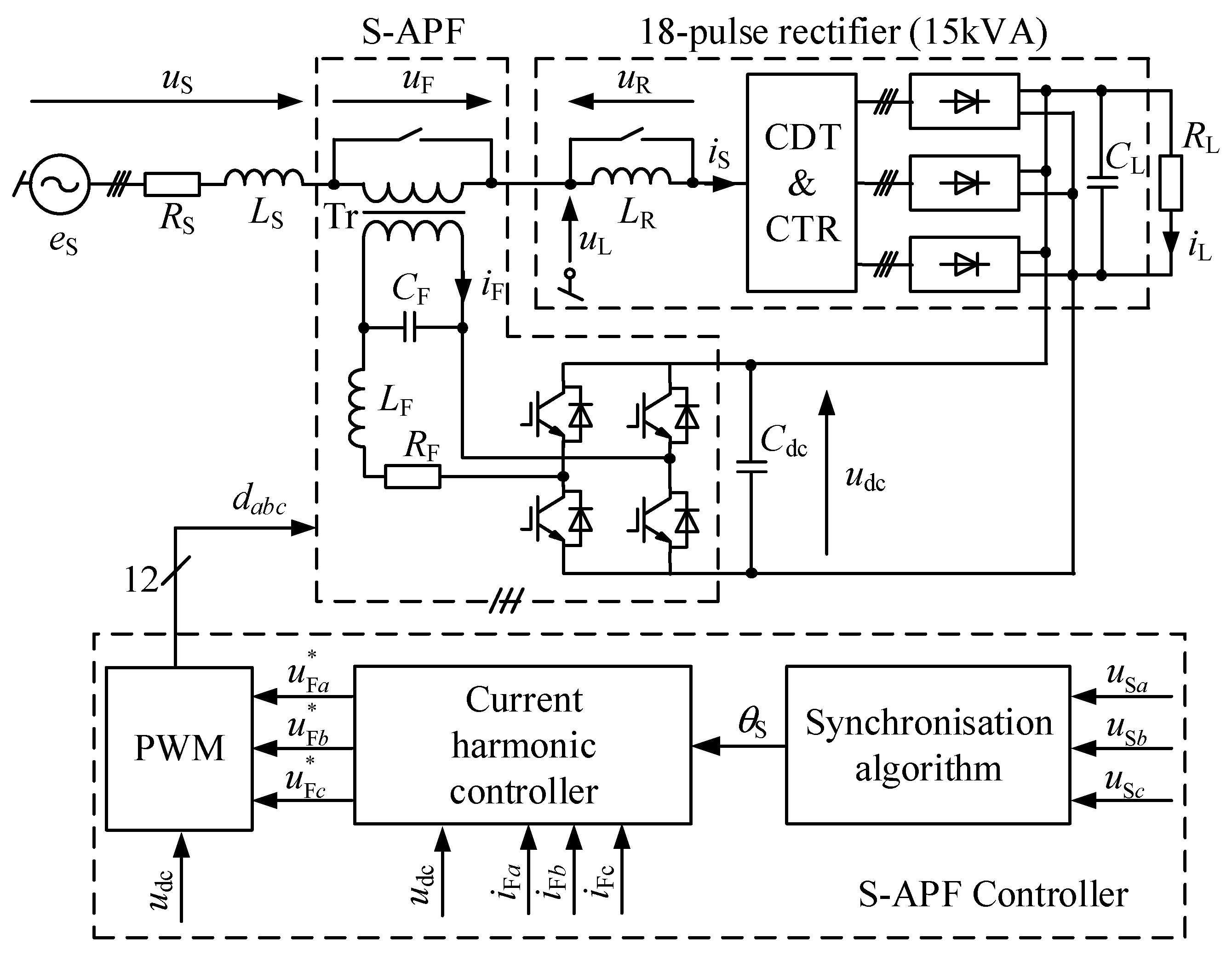
A simplified schematic diagram of the analyzed ac/dc supply system is shown in
Figure 1.
Three-phase supply is modeled by the voltage source
eS, resistance
RS, and inductance
LS, which also represents the leakage inductance of a rectifier’s magnetic circuits. The system is composed of two separate modules: an 18-pulse rectifier, and a series active filter. Three system configurations are possible: (1) only 18-pulse rectifier, (2) rectifier with additional series reactor, and (3) rectifier with the series active filter. The main element of the system is the 18-pulse rectifier based on current dividing transformer (CDT) for preliminary current division, and the set of coupled three-phase reactors (CTR) [
5]. The above magnetic elements compose three 3-phase voltage systems, shifted by 20° in relation to each other. Six-pulse rectifiers with a shared output capacitor are connected to CTR outputs. The 18-pulse rectifier enables reduction of undesired higher harmonics from the supply network currents, mainly of the order of 5, 7, 11, and 13.
The series active filter consists of three single-phase circuits, each composed of a voltage source inverter (VSI) with IGBTs transistors. The dc circuits of these inverters are connected to the output of the 18-pulse rectifier. The ac sides of the inverters are series-connected to the supply voltage via LC filters and step-up transformers (Tr) with voltage ratio 1:12. During system start-up and operation only with the rectifier, the S-APF is bypassed by a contactor.
The parameters of the converter system are given in
Table 1. The supply resistance and inductance were measured using the loop impedance meter. The series injection transformer (Tr) was selected through simulation research, based on the results presented in [
8,
13]. The transformer is represented by its classical circuit model, excluding a magnetizing branch. The transformer parameters listed in
Table 1 were determined on the basis of a short-circuit test.
The inductance (
LF) and capacitance (
CF) of the switching ripple filter were selected assuming the maximum ripple of the inductor current and the capacitor voltage.
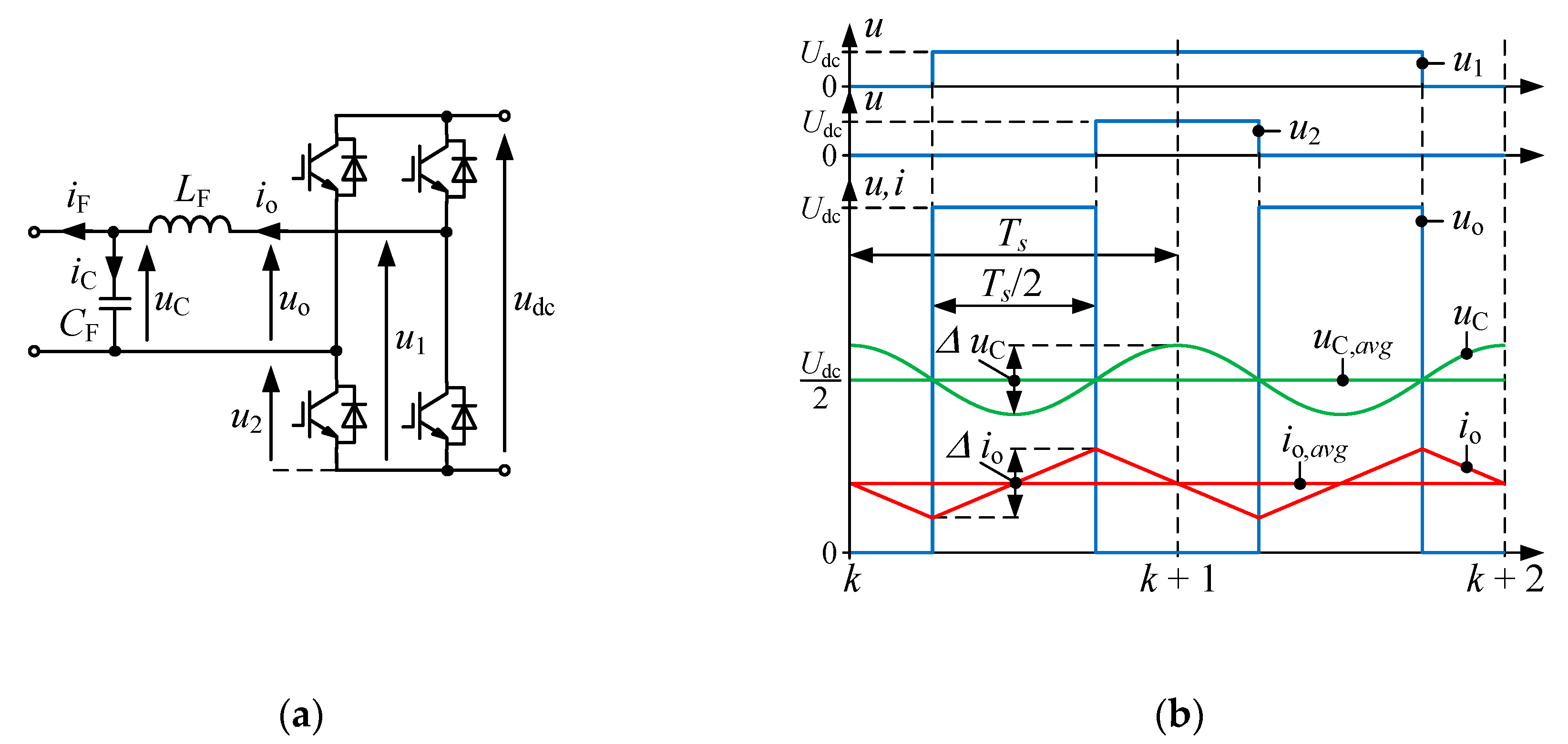
Figure 2a shows a simplified circuit diagram of the VSI and its output filter to define the signals, the waveforms of which are presented on
Figure 2b. It shows the branch voltages
u1,
u2 and the output voltage
uo of the VSI, as well as the capacitor voltage
uC and its averaged value over the sampling period
uC,avg. In addition to the voltages, the figure also shows, in an idealized way, the VSI output current
io and its averaged value over the sampling period
io,avg. In the case of unipolar modulation with the double update mode the largest ripples of inductor current occur when the duty cycle
m =
uo/
udc is equal to 0.5. The simplified waveforms in
Figure 2b apply to this case.
Taking into account the time interval of length
Ts/2 (
Figure 2b), in which the current
io increases from the minimum value to the maximum, the peak-to-peak value of the current ripple ∆
io can be calculated from the formula [
14]:
where
Udc is the maximum
dc link voltage equal to 500 V.
Lower current ripple reduces inductor high frequency losses and for this reason a choke with a relatively high inductance LF = 20 mH was selected. The maximum current ripple is at 11% of the peak nominal input current of the 18-pulse rectifier current, referred to the primary side of the transformer Tr.
Considering the time interval
Ts/2, in which the capacitor voltage
uC varies from the minimum to the maximum value (
Figure 2b), the maximum capacitor voltage ripple ∆
uC can be estimated by the equation [
14]:
It was assumed that the capacitor voltage ripple should not exceed 1% of the peak output voltage of the VSI, which is equal to Udc in the worst case. Finally, the value of CF = 560 nF was selected, for which maximum ∆uC equals 3.5 V (0.7% of the Udc).
The control algorithm was implemented in the microprocessor controller based on the digital signal processor TMS320C6713 and the programmable system FPGA Cyclone IV. To execute the control algorithm, measurements were performed of the supply network phase voltages (uSa, uSb, uSc), transformer phase currents (iFa, iFb, iFc) on the inverter side, and the rectifier output voltage udc.
3. The Structure of Multiple Reference Frame Current Controller
The task of the series active filter is to improve the quality of the supply current by suppressing higher harmonics and compensating the asymmetry of the fundamental components. A simplified schematic diagram of the S-APF control system is shown in the lower part of
Figure 1. Three functional blocks are singled out in this part: pulse width modulator (PWM), synchronization algorithm [
12,
15], and the current controller, which will be described in detail further in the article. It was developed on the basis of the research results reported in [
12,
16,
17,
18].
In order to implement the control system, the three-phase quantities
xa,
xb, and
xc were converted using the space vector defined as:
In steady state, the current space vector
can be approximated by a complex Fourier series given by the formula:
where
is the complex-valued amplitude of
m-th current harmonic belonging to the set of
M dominant harmonics to be suppressed;
ω1 is the frequency of the fundamental component, and
θ1 is its instantaneous phase.
The 18-pulse rectifier draws the distorted current from the supply source. The dominating frequencies in this current are of the order of
m = −17, 19, −35, 37, … while the harmonics of the space vector of supply network voltage are usually of the order of
m = −1, −5, 7, −11, 13, …, where the component
m = −1 represents the asymmetry of fundamental components of phase voltages. Suppressing the harmonics of the above orders is the basic task of the proposed current controller. Additional S-APF functions, requiring the adjustment of the fundamental harmonic of the rectifier supply voltage, such as the power factor compensation or stabilization of the rectifier’s output voltage are not implemented in considered system. They require the use of a series transformer with a higher rated power and an appropriate voltage ratio and also increase the S-APF power losses [
13].
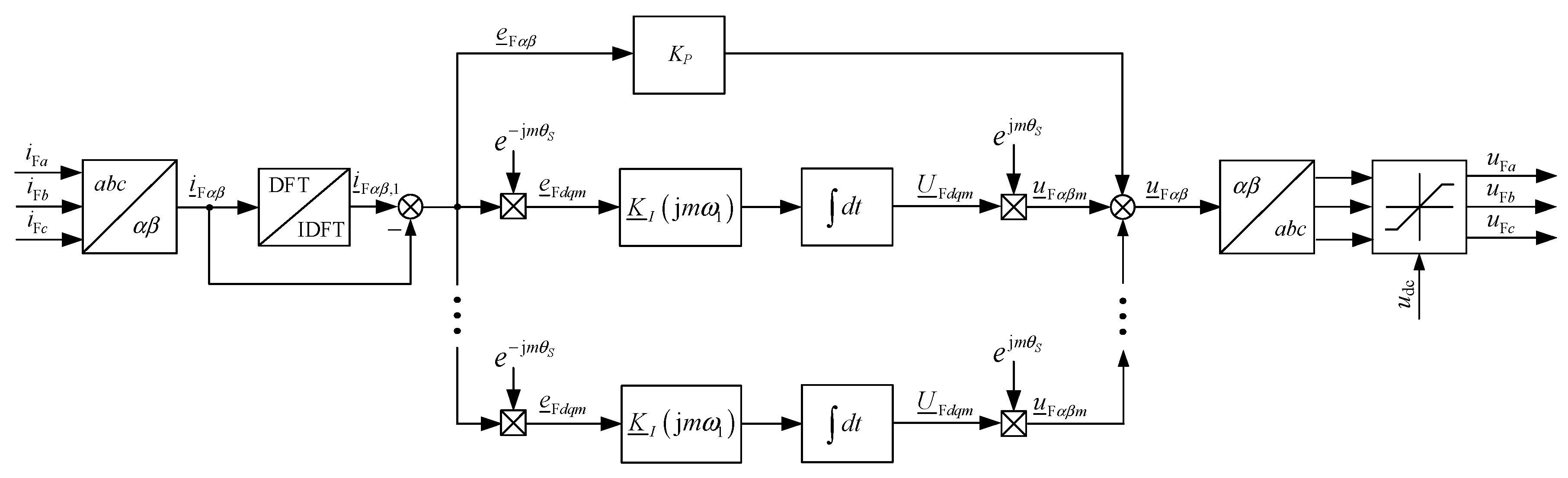
The block diagram of the current controller is shown in
Figure 3. To limit the S-APF power losses related to the first harmonic, the proposed current controller should not affect the fundamental component of the current taken from the supply network. Consequently, this harmonic was removed from the space current vector
using the fundamental component filter [
12] based on recursive discrete Fourier transform. The signal
created in the above way is the control error, assuming that the reference value for all compensated current harmonics is zero.
The error signal is given to the input of the proportional term of the current controller, and to the inputs of the integral terms implemented in the synchronous coordinate systems
dqm, the number of which is equal to the number of compensated current harmonics. The error signal is converted to
m synchronous coordinate systems by multiple Park transformations defined by the formula:
where
is the error signal converted to the coordinate system
dqm rotating with frequency
mωS,
ωS is the estimated frequency of fundamental component, and
θS =
ωSt is the estimated instantaneous phase. After transformation, the control error harmonic of the order
m becomes a constant component in
dqm frame and is amplified by the integral term of current controller which corresponds to this harmonic. Simultaneously, the remaining harmonic components in the output signal
are suppressed:
where
k0 is the time of control algorithm activation, and
is the complex-value gain of the frequency-dependent integral term of the controller.
In the proposed controller implementation, the integral gain is a complex number which also determines relevant phase shift of the output signal of this block after its reconversion to the coordinate system
αβ using the inverse Park transform:
The sum of output signals from particular integral terms and from the proportional part is the controller output signal in the coordinate system
αβ.
when it is too large, the modulus of the output voltage space vector
is limited to the voltage in the
dc circuit. The calculated output signal from the current controller is passed to the input of pulse width modulator.
4. Selection of Controller Settings
When selecting controller settings, the magnetizing branch in the transformer model was omitted. Then, the transfer function of the circuit coupling the inverter with the supply network takes the form:
Selection of controller settings started with determining the gain of the proportional part of the controller. This setting was calculated based on the assumed gain margin for the open-loop system working only with the proportional controller. For the assumed gain margin of 10 dB, the calculated proportional coefficient was equal to Kp = 44.
To select the integral gains, the current control system was treated as a multiloop scheme, the inner feedback loop of which consists only of a proportional term [
18]. Then, the integral gains were selected in such a way as to compensate the remaining errors for the frequencies of dominant harmonics. The error which should be compensated by the integral terms is given by the following transfer function:
where
EFαβ(
s) is the Laplace transform of the control system error,
UI(
s) is the Laplace transform of the output signal of the integral part (corresponding to the sum of output signals from individual integral terms), and
Gcp(
s) is the transfer function of the closed-loop system when only the proportional controller is used:
Figure 4 shows the Bode plots of the open and closed-loop control system with only the proportional term. The proportional controller with fixed setting is not able to suppress harmonics effectively. The task of the integral terms is to increase controller gain for selected frequencies. Considering the formula (8), the transfer function of the integral term of the proposed controller in the stationary coordinate system
αβ is as follows:
in which the complex-value integral gain, shown in the scheme in
Figure 3, is given by:
where the controller integration time was assumed equal to
Ti = 0.5
/f1 = 10 ms.
The gains of the integral terms have complex values and ensure proper phase correction of particular output signals uFαβm, without additional trigonometric function calculations.
5. Laboratory Results
To verify the operation of the S-APF control algorithm, a series of experimental tests were performed. The task of the current controller was to suppress current harmonics of the following orders: −1, ±3, ±(6
n ± 1) for
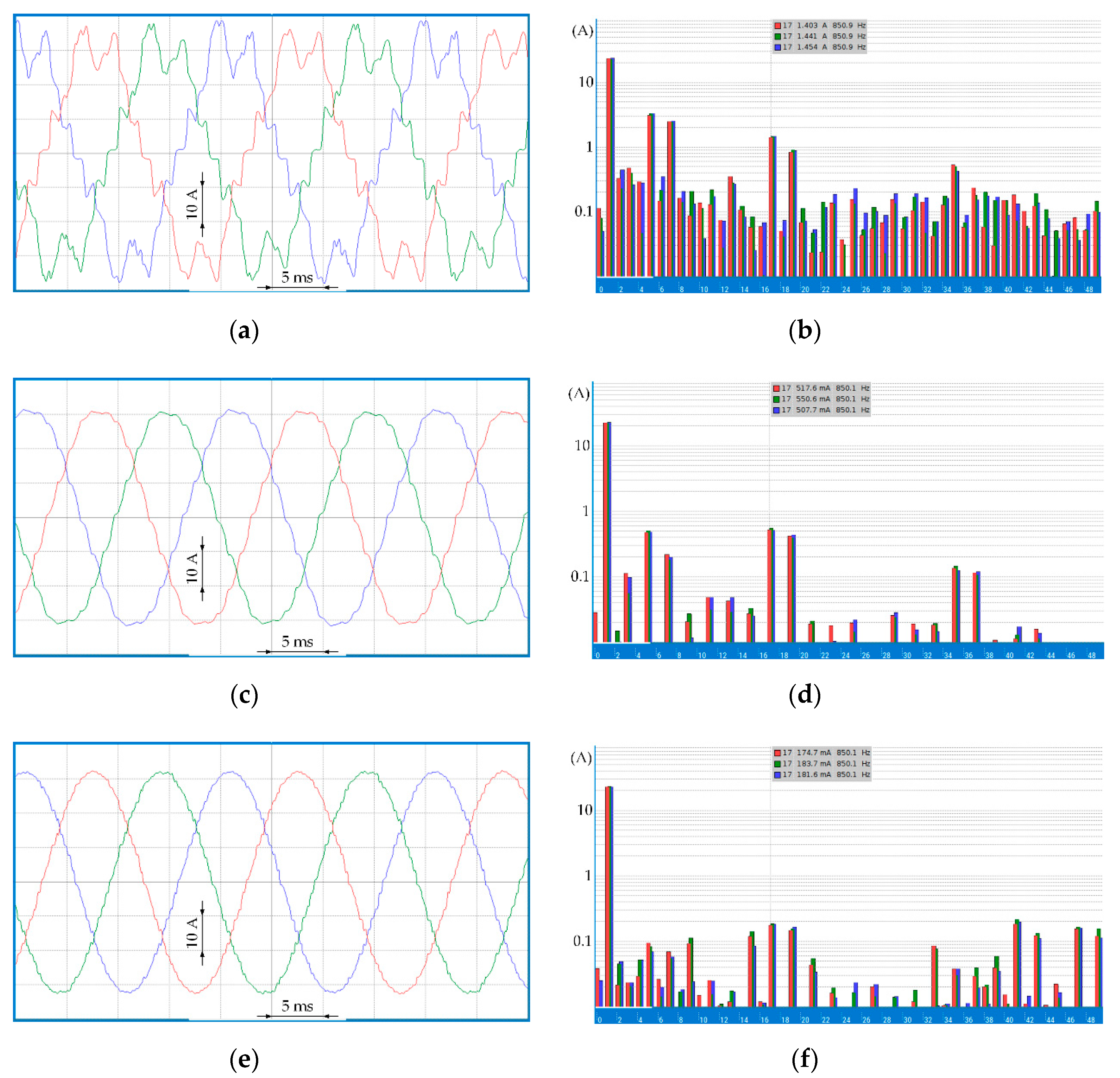
n = 1, 2, …, 6. Firstly, the steady-state operation of the current control system was tested. The obtained results were compared with the data recorded for two remaining configurations of the converter system.
Figure 5 shows sample oscillograms of supply currents and their amplitude spectra recorded at nominal load: (1) for only 18-pulse rectifier (
Figure 5a,b), (2) for rectifier with additional series reactor
LR (
Figure 5c,d), and (3) for rectifier with series active filter (S-APF) (
Figure 5e,f). The waveforms of the phase currents with their amplitude spectra and THD (total harmonic distortion) values were recorded and calculated using the Precision Power Analyzer LMG670 made by Zes Zimmer. The amplitude spectra of the supply currents are given in logarithmic scale.
The amplitudes of the dominant harmonics are the lowest when using S-APF. In each spectrum shown in
Figure 5, the amplitudes of the 17-th harmonic (about 850 Hz) are marked for three phase currents. The application of the series reactor reduced the values of this harmonic from the level of 1.433 A to 0.525 A, while the use of S-APF to the level of 0.180 A. In general, all dominating harmonics considered in the current controller with S-APF were reduced, as compared to the remaining configurations.
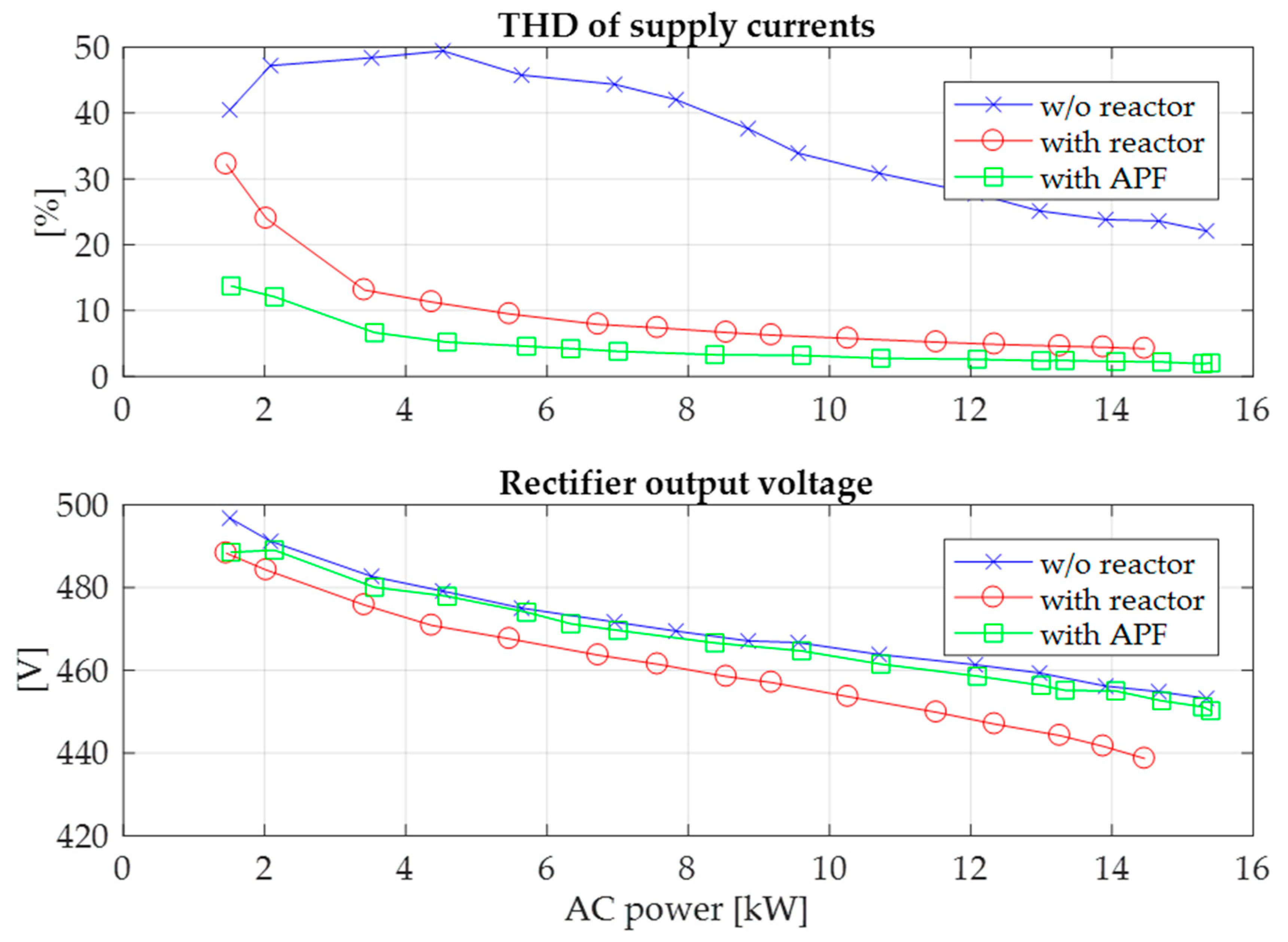
Figure 6 shows the results of measurements of supply current THD and output voltage for three system configurations. The introduction of a series reactor alone has already reduced significantly the harmonic distortion of supply currents as compared to the autonomous operation of the 18-pulse rectifier. Replacing the reactor
LS with the S-APF system improves the quality of supply currents within the entire output power range. For the configuration with S-APF operating at nominal load, the THD of supply currents remains at the approximate level of 2%. Significant improvement in quality of supply currents can be observed during converter system operation at low load. Compared to the configuration with additional series reactor, the system with S-APF also ensures slightly higher output voltage.
Figure 7,
Figure 8 and
Figure 9 show sample results of converter system examination in dynamic states. The values of supply network currents were measured and recorded in the converter control system unit. To illustrate the quality of the controller’s performance, THD values of the supply current are shown, which were obtained from harmonic values calculated in moving window with fixed width corresponding to frequency 50 Hz:
where
is the amplitude of
m-th harmonic of the supply current converted to the coordinate system
αβ, calculated in the moving window, and
is amplitude of fundamental harmonic of the supply current.
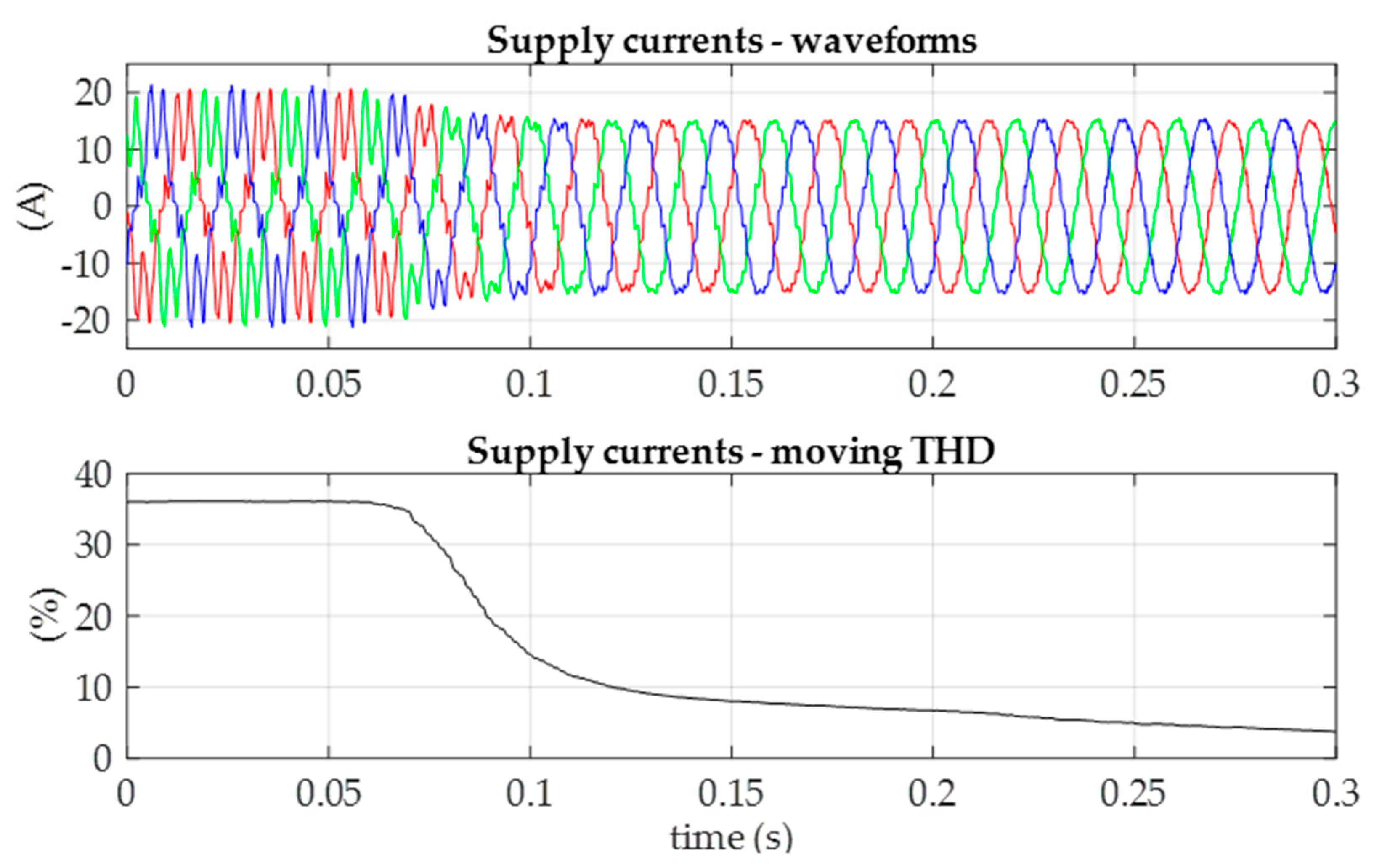
Figure 7 shows the waveforms of supply network currents and THD values after control algorithm activation when the system is loaded with half of the nominal power. During two supply network voltage periods, significant reduction in the level of harmonic distortion is observed, from about 36% to 14.5%, with further slower reduction to the approximate level of 3.7%.
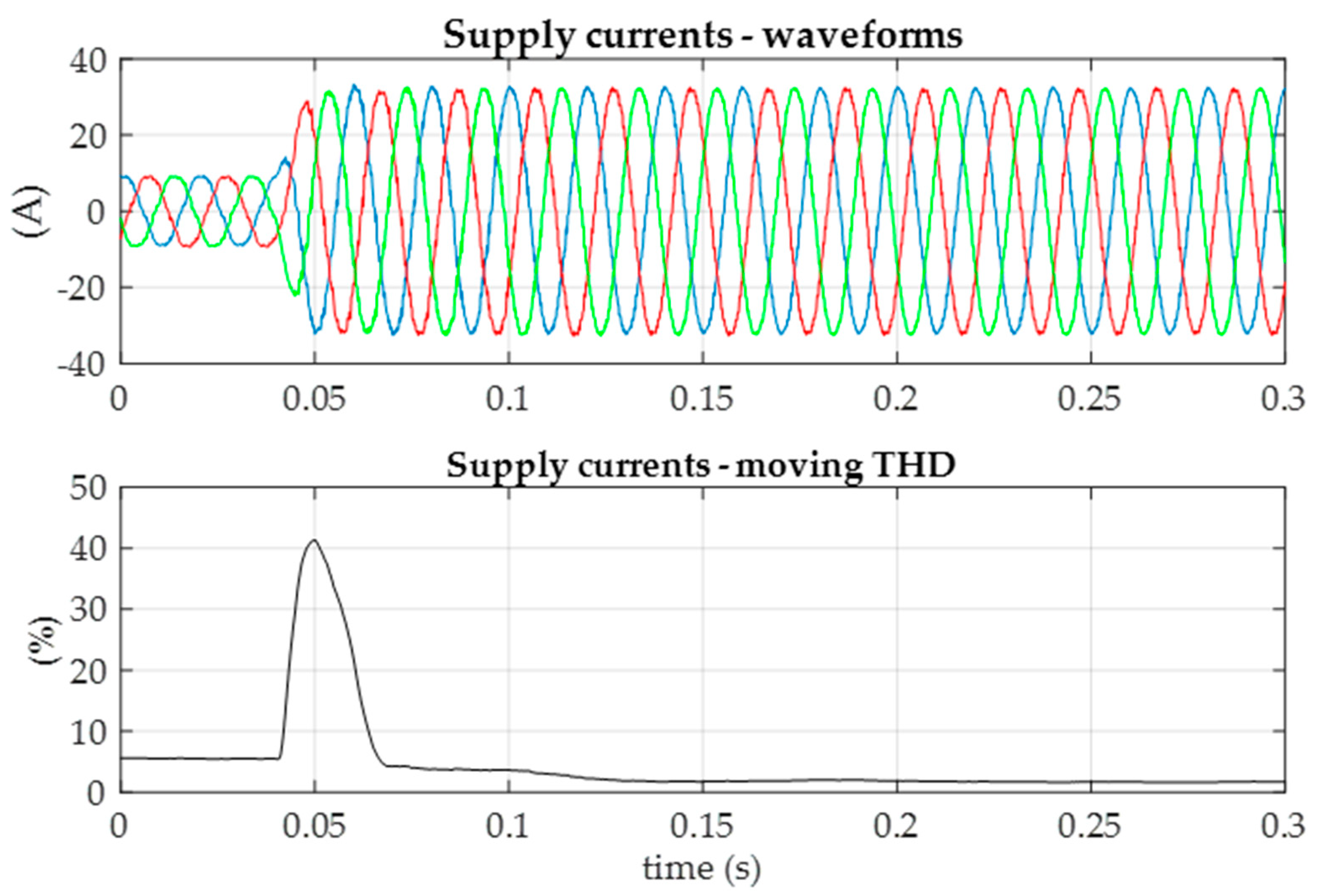
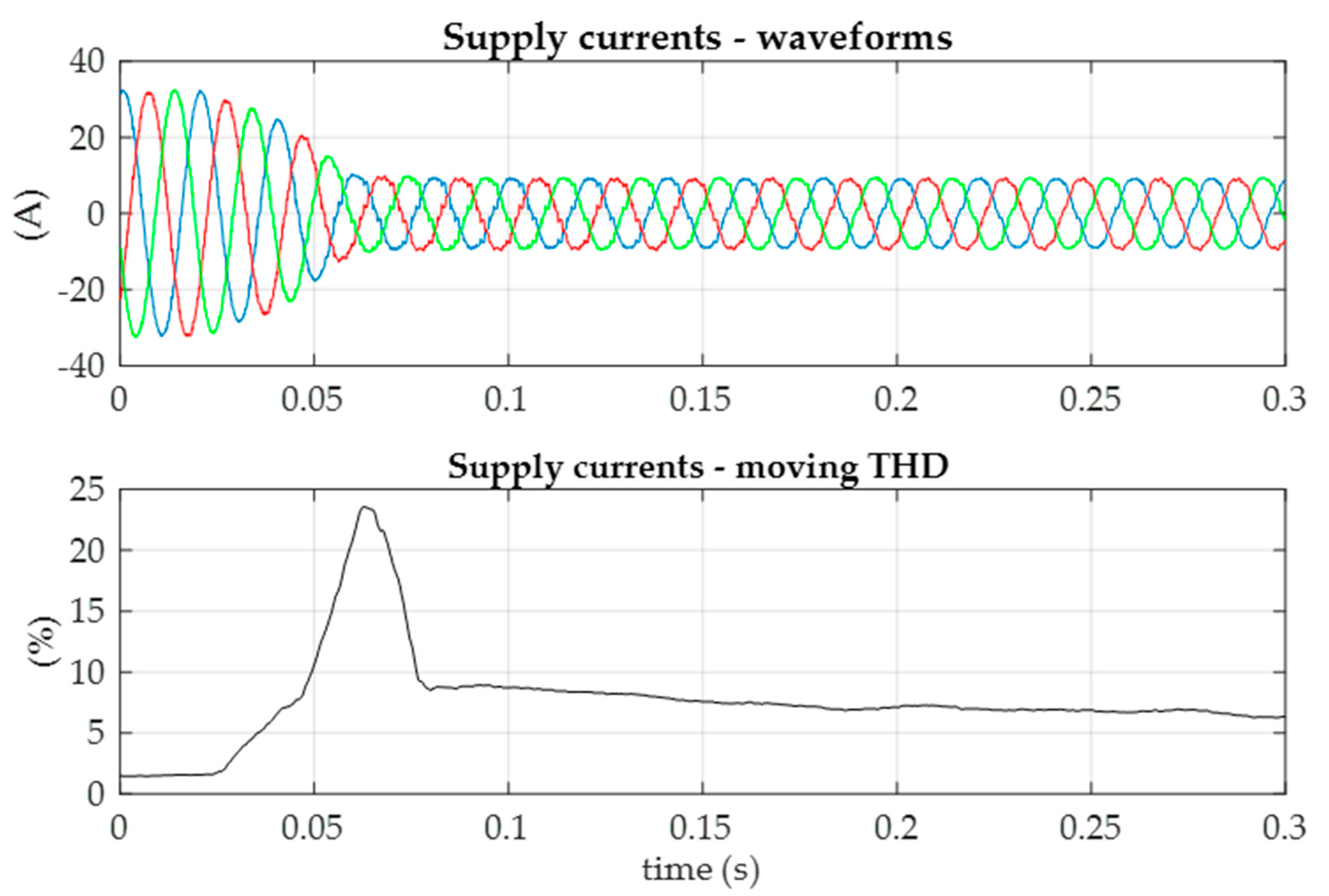
Figure 8 and
Figure 9 show sample transient states related with load change at converter system output.
Figure 8 presents the step increase of load from 33% to 100%, while
Figure 9 shows the reverse situation, i.e., rapid load drop.
In both situations, the converter system operation is stable and leads to the reduction of supply current harmonic distortions after the transient state. Unfortunately, during transients the THD values are not a meaningful indicator and reach disproportionately high values in relation to the level of distortion visible in the current waveforms.
6. Conclusions
The article proposed a current harmonic controller for a series active filter integrated with 18-pulse diode rectifier with coupled reactors. The ac sides of S-APF inverters were coupled with booster transformers via LC filters, which enables significant reduction of booster voltage ripples, but may lead to unstable operation of the converter system.
To suppress undesired harmonics in supply currents, a proportional controller was used with integral terms implemented in multiple coordinate systems, rotating synchronously with angular frequencies of the dominant harmonics. The use of integral gains with complex values, ensures proper phase correction of integral’s output signals and stable operation of the converter system.
The proposed current controller suppresses dominating harmonics up to the order of 37. For nominal load, the controller can reduce the THD coefficient from 22% to about 2%.


