1. Introduction
Turbopump-driven liquid-rocket engines can generally be divided into gas-generator-cycle, expander-cycle, and staged-combustion-cycle types. In a gas-generator system, a portion of the propellant is burned within the gas generator to drive the turbine and is then discharged to the outside; here, the propellant supply pressure required for turbopump is relatively low, making it easy to develop and manufacture. However, such systems have the disadvantage of a propellant efficiency that is several percentage points lower than that in other systems, as the propellant burned inside the gas generator is dumped outside the turbine [
1,
2]. Expander-cycle systems are relatively simple, using a structure in which the vaporizing propellant is cooled in a cooling channel before entering the main combustion chamber that drives the turbine; however, it is difficult to increase the combustion-chamber pressure due to the limited degree of propellant heating in the regenerative cooling channel. Staged-combustion-cycle configurations achieve efficiency by sending the turbine-driven gas back into the main combustion chamber for reburn, although the pressure required by the pump is high and the structure is complicated [
2,
3]. Staged-combustion-cycle engines are the most widely used, due to their ease of re-ignition and high specific impulse. This type of engine can be further divided into fuel-rich-combustion and oxidizer-rich-combustion subtypes. An example of fuel-rich combustion is the RS-25 engine used on the space shuttles, with liquid hydrogen and liquid oxygen as propellants [
3]. In oxidizer-rich combustion, kerosene and liquid oxygen are mainly used as propellants: examples include Russia’s RD-170, or the American AR-1; engines that use liquid methane and liquid oxygen as propellants, such as the Raptor or BE-4, are also being developed [
4,
5,
6].
The gas-centered-swirl-coaxial (GCSC) injector used in oxidizer-rich staged-combustion-cycle engines has a structure that mixes the hot gas burned in the oxidizer-rich condition in the preburner with the fuel that cools the combustion chamber as it passes through the cooling channel; the mixture is then sprayed into the combustion chamber. Such injectors have mainly been developed by Russia in the past, but unfortunately, records of their characteristics are hard to find. Recently, with the development of staged-combustion-cycle engines by the United States, China, and other countries, studies of GCSC injectors have been conducted. In particular, the characteristics of the propellant mixture have been determined through spray testing, numerical analysis, and flow-instability modeling according to the shape of the injector. Jeon et al. [
7] studied spray characteristics according to the gas–liquid momentum-flux ratio (
) and recess length through cold-flow tests. Kim et al. [
8] analyzed the spray characteristics of the fluid at atmospheric and high pressure in terms of the momentum-flux ratio via spray visualization. This showed that, as the momentum-flux ratio increases, the spray angle decreases until a certain limit is reached. Kang et al. [
9] experimentally observed that the size of the sprayed droplet breaks up rapidly as the gas-flow rate increases. Balance et al. [
10] visualized the flame-stabilization region under high-pressure conditions using gas–liquid propellant. Using numerical analysis, the propellant mixing, flame formation, and flow instability were studied under supercritical conditions for various shapes of 2D and 3D injectors [
11,
12]. Park et al. [
13,
14] investigated the instabilities and characteristics of the flow of the gas and the liquid, respectively, for the GCSC injector; when a perturbation was applied to each fluid, the momentum of the gas was transferred to the liquid as the momentum-flux ratio increased in both cases and the gain value increased accordingly.
The previous studies have focused mainly on the characteristics of injector mixing in single-injector or non-reacting flows, but it is necessary to study how the momentum-flux ratio relates to combustion efficiency in tests in which a large number of injectors are applied in actual combustion environments. In this paper, the effects of the momentum-flux ratio upon the combustion-performance of a full-scale 9-tonf staged-combustion-cycle engine combustion chamber were analyzed experimentally under variation of the shape of the injector, the mixture ratio, and the number of injectors. Among the various methods used to increase the performance of full-scale rocket engines, there are ways to increase the efficiency within the combustion chamber. This efficiency can be obtained by identifying the combustion’s characteristic velocity, which is the virtual thrust per unit mass with which the pressure in the combustion chamber acts on chamber’s neck. It can be obtained from the pressure of the combustion chamber, the combustion rate of the propellant, and the cross-sectional area of the nozzle as [
1,
2,
15]
To this end, a 9-tonf full-scale staged-combustion-cycle engine was manufactured, and combustion tests were performed according to the momentum-flux ratio of the GCSC injector in an actual combustion environment with various combustion pressures and mixture ratios. The combustion’s characteristic velocity results were calculated and analyzed.
2. Material and Methods
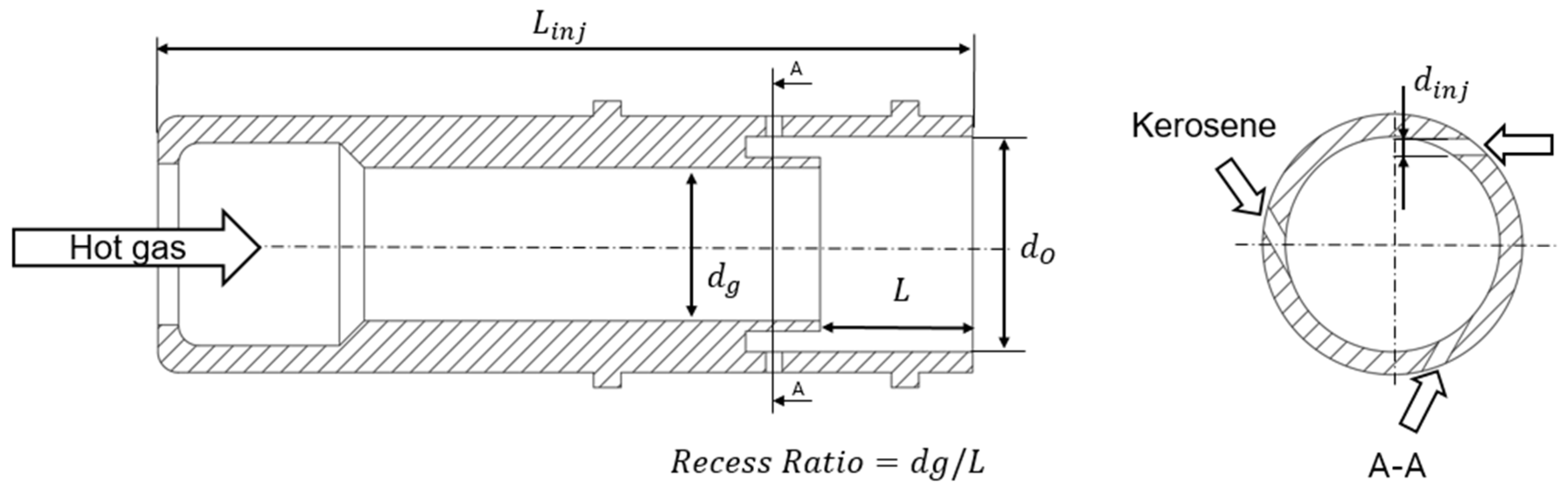
As shown in
Figure 1, The injector used in the experiment is a GCSC injector from which hot gaseous oxygen (GOx) is sprayed from the center and kerosene used to cool the combustion chamber is injected through the annular hole. The injector has three shapes depending on the velocity of GOx and its outer diameter; the A-type injector is designed such that the flow velocity of GOx injected from the center will be 100 m/s; the B-type is designed to have a flow rate of 75 m/s at the center, such that the inner diameter of the injector from which GOx is sprayed is larger than in the A-type case. The C-type injector is designed to have GOx flow rate of 100 m/s, which is the same as the A-type; however, as the total number of injectors used in the full-scale combustor is smaller than the A-type, the injector diameter is designed to be larger than that of the A-type to equalize the amount of propellant flow injected into the combustion chamber. All injectors have a recess ratio of 1.0.
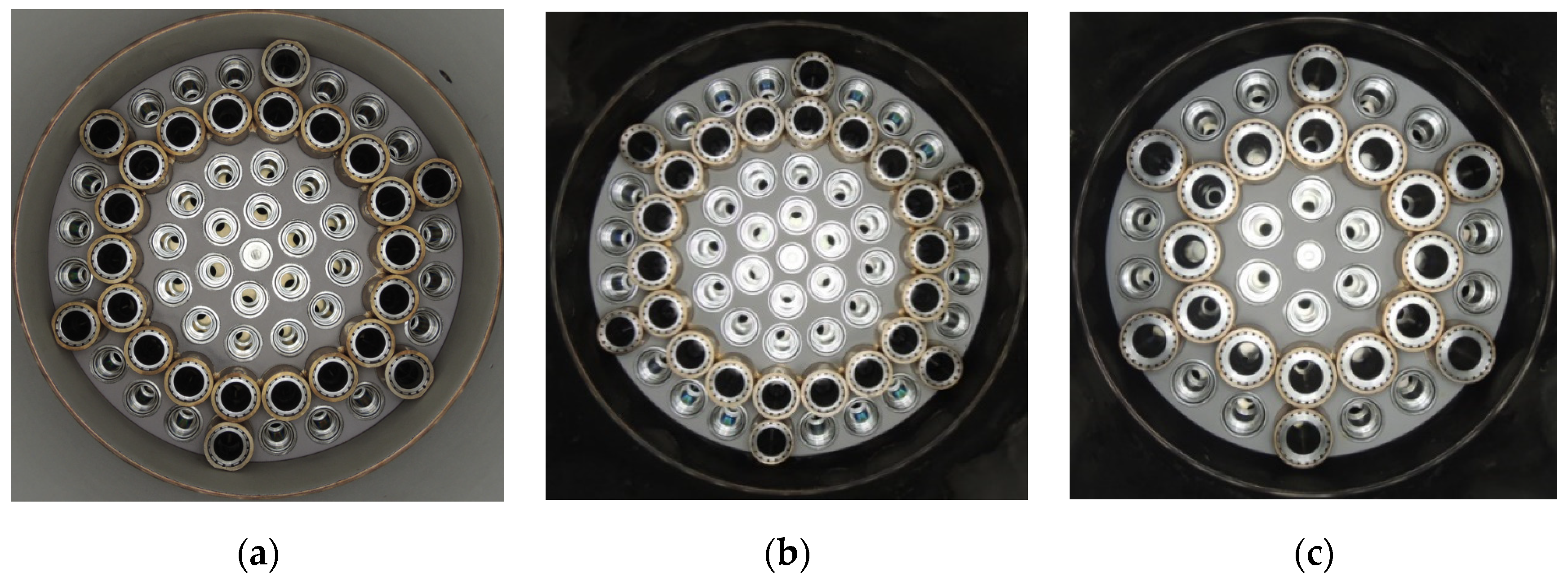
Combustor heads were manufactured with two types of arrangements according to the injectors’ shape as presented in
Table 1.
Figure 2 shows the combustor heads for the A-type and the B-type configurations comprise 61 injectors. A hypergolic injector is placed at the center of the faceplate of the combustor head, with 6 main injectors in the first row and 12 main injectors in the second. In the third row, 18 baffle injectors are arranged to suppress combustion instability. The 4th row comprises 6 sections of 3 main injectors, with individual baffle injectors dividing each section to prevent combustion instability. The C-type combustor head has a total of 37 injectors: a hypergolic injector is again centrally located, with 6 main injectors in the first row, 12 baffle injectors in the second row and 6 sections of 2 main injectors in the third row, with individual baffle injectors dividing each section.
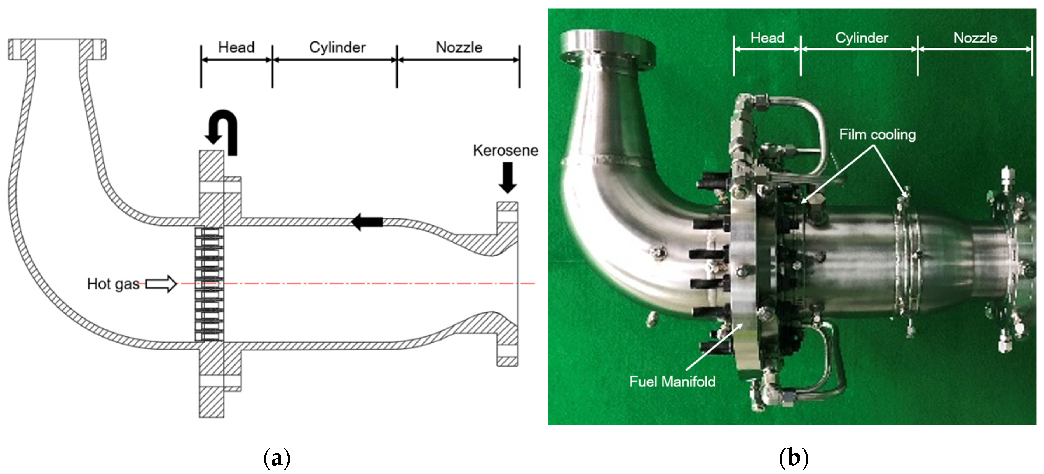
The combustor consists of a separate combustor head with injectors and a combustion chamber, as shown in
Figure 3. The combustion chamber can be reused because it is designed to have a bolting structure that allows separation and recombination of the combustor heads for various injector shapes. Within the curved part of the combustor head through which the pre-burned GOx flows, an oxidation-resistant coating was applied to protect the wall’s surface from the hot gas flowing from the turbopump, and to prevent ignition due to particles that may occur in the preburner. The combustion chamber is designed with regeneration and film cooling, and the
thermal-barrier and Ni-Cr coatings are applied to protect the combustion chamber’s inner wall from the combustion flame. The high-pressure kerosene that is discharged from the fuel pump flows into the nozzle end, cools the nozzle inner wall, and passes through a film-cooling ring located at the bottom of the combustion chamber cylinder. After cooling the wall of the bottom combustion-chamber cylinder, kerosene passes through a film-cooling ring located at the top of the combustion-chamber cylinder and then enters the fuel manifold of the combustion-chamber head before being sprayed into the injector. To measure the temperature of kerosene passing through the cooling channel of the combustion chamber, temperature sensors were installed in the manifold of the combustion-chamber head fuel, two film-cooling rings, and manifold at the end of the nozzle. This combustor was designed to test the performance characteristics of the GCSC injector; thus, the length of the combustion chamber and the expansion ratio of the nozzle were designed to be relatively short as 2.3 to fit the vertical-combustion-test facility.
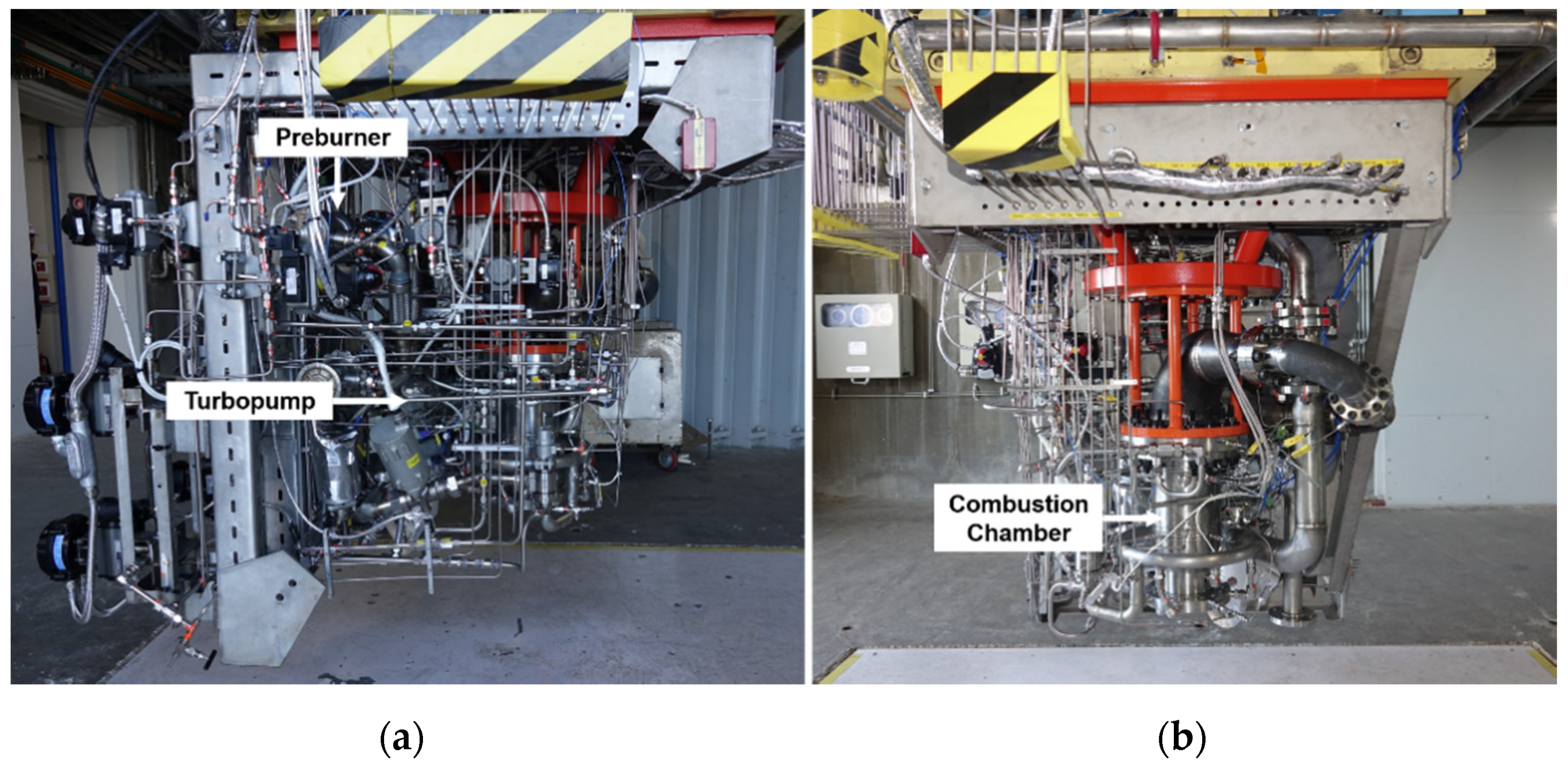
The 9-tonf staged-combustion-cycle engine consists of a preburner, a combustor, a turbopump, pneumatic-control valves, and piping, as shown in
Figure 4. This engine is designed for the development of preburner and combustor technology for staged-combustion-cycle engines. Unlike general liquid-rocket engines that combine a combustor and a turbopump, the turbopump and the combustor are here assembled as separate structures with a certain distance between them to facilitate disassembly and replacement of the combustor. In addition, to protect the engine’s components from accidents that may occur during the firing test, major parts such as the servo valves and the hypergolic-propellant ampule are placed on opposite sides with a thick steel plate between them. The combustion-pressure-control and mixture ratio control valves of the combustor are installed at the exit of the first- and second-stage fuel pumps, respectively. Liquid oxygen and kerosene propellants supplied from the test facility enter the turbopump, where they are highly pressurized and supplied to the preburner. Propellants burned inside the preburner become oxygen-rich hot gases and enter the gas injectors of the combustor. The fuel supplied from the first-stage fuel pump of the turbopump passes through the combustor’s mixture ratio control valve and enters the nozzle end of the combustor to cool the combustion-chamber wall through cooling channels and film cooling. Thereafter, the fuel supplied to the combustor head is injected into the combustion chamber through the annular injector, along with the pre-burned high-temperature oxygen-rich gases. The engine is started by supplying high-pressure helium to the starting turbine of the turbopump. The engine-combustion test is performed by supplying hypergolic propellant to the preburner and the combustor in accordance with a pre-set sequence.
Combustion tests were conducted for pressures between 81 bar and 105 bar (i.e., approximately ±10 bar of the design combustion pressure of 95 bar), and for mixture ratios between 2.2 and 2.75 (i.e., approximately ±12% of the design mixture ratio of 2.5), as shown in
Figure 5. The velocities of the injected gas were calculated based on the pressure, temperature, density, and flow rate of the injector, as obtained from the gas properties of the preburner and the combustor head; this was done to allow analysis of the combustion efficiency according to the momentum-flux ratio. Also, the material properties and flow rate of kerosene flowing into the combustor were measured 1000 times each second based on data from pressure and temperature sensors and flowmeters installed in the engine and the test facility in order to calculate the speed of the liquid propellant. From the law of mass conservation, the velocity of the oxygen-rich hot gas,
, and the axial liquid velocity,
, were calculated, and the thickness of the liquid film sprayed from the annular fuel injector,
, was derived using the expression of Suyari and Lefebbre [
1,
16]:
3. Results and Discussion
Combustion tests were conducted from 2 s up to 114 s for combustor heads applying with 3 types of injectors as shown in
Figure 6. The tests were performed while varying the mixture ratio and combustion pressure for different injector shapes. The engine-start ignition sequence, engine-thrust-control-performance verification, and engine-performance tuning were mainly performed in the A-type injector tests. As shown in
Figure 7, five seconds after the initial start, the combustor pressure was about 89 bar and remained stable for about 25 s. Although the engine was operated at a somewhat lower pressure than the design target due to the simultaneous research and development of the staged-combustion-cycle engine and combustor, it is meaningful that the engine successfully performed the firing test for the first 30 s or more without damaging the hardware through several combustion tests. In B-type injector tests with an optimized engine-starting ignition sequence, off-design operating-point tests were performed for combustion pressures between 83 bar and 105 bar and mixture ratios of 2.2 to 2.75. Based on the performance characteristics of the developed staged-combustion-cycle engine under A-type injector testing, it is possible to control the propellant-flow rate, enabling experimentation under the design operating-point and off-design operating-point test conditions. For the C-type injector, tests of up to 114 s were performed under operating conditions similar to those of the B-type tests with combustion pressures from 85 to 105 bar and mixture ratios of 2.2 to 2.75.
Figure 8 shows the characteristic velocity calculated from the measured combustion pressure and flow rate into the combustor under each test condition for various injector shapes. All data used in the calculations represent average measurements over one second in an interval with stable combustion pressure. In the A-type case for which the tests were conducted under combustion pressures lower than the design pressure, the combustion-characteristic velocities were distributed at points above 1700 m/s. In the B-type case, which has the same number of injectors, the gas velocity is lower than in the A-type case and the characteristic velocities are distributed from 1665 to a maximum of 1690; it can be seen that the higher the gas velocity under the same combustion pressure, the higher the characteristic velocity. In the C-type case, which had the same gas velocity as the A-type but a smaller number of injectors, the characteristic velocities were distributed between 1640 and 1675. Thus, at constant gas velocity, a greater number of injectors translates into better combustion characteristics. Additionally, for all injector shapes, the higher the combustion-chamber pressure, the higher the combustion efficiency.
In a full-sized engine, the momentum-flux ratio can be changed by controlling the propellant mixture ratio. The characteristic velocity results for each injector shape are shown in
Figure 9 according to the momentum-flux ratio with uncertainty [
17,
18,
19]. A-type tests were conducted at momentum-flux ratios between 20 and 22.5, with an average characteristic velocity of 1704. The B-type combustor was tested at lower momentum-flux ratios due to the relatively slow gas velocity, although the total injector quantity was the same as that of the A-type combustor. The average characteristic velocity of the B-type combustor with an average momentum-flux ratio of 11.9 is 1681. The C-type injector was designed to have the same gas velocity as the A-type injector, but tests were performed at momentum-flux ratios similar to that in the B-type case due to the large fuel flow rate per injector. The average characteristic velocity for the C-type injector was for 1665 for an average momentum-flux ratio of 12. For tests of the A-type and B-type combustors with 61 GCSC injectors, the characteristic velocity tends to increase linearly in proportion to the momentum-flux ratio; however, for the C-type combustor with 37 injectors, the characteristic velocity decreases as the momentum-flux ratio increases.
The characteristic velocity and efficiency results at the design pressure of the combustor, 10 bar higher than the design pressure, and 10 bar lower than the design pressure are shown for each injector shape in
Figure 10 and
Figure 11. The B-type test results show a high characteristic velocity on average under high-pressure test conditions, and in design pressure and low pressure test conditions, the maximum characteristic velocity values are 12 and 13 momentum-flux ratio, respectively, which is the design mixture ratio. Furthermore, the higher the deviation from the design mixture ratio, the lower the characteristic velocity. The characteristic velocity reaches a maximum of about 1690 under the design pressure and design mixture ratio. The C-type test results also tended to increase the combustion-characteristic velocity along with the combustion pressure. The highest combustion-characteristic velocity was 1676 under the design pressure and design mixture ratio test conditions, but this velocity tended to decrease as momentum-flux ratio increased. In other words, for a constant combustion pressure, increasing the momentum-flux ratio does not necessarily affect the direction in which the combustion-characteristic velocity is increased; and it can be seen that there exists an optimum pressure and mixture ratio that yield the maximum mixing performance depending on the GCSC injector shape.
The actual combustion environment has a lower combustion-characteristic velocity than the ideal situation due to factors such as the degree of mixing of the propellant, incomplete combustion, and heat loss due to heat flux. Thus, we defined the combustion-performance efficiency as
[
20]. To analyze the combustion-performance efficiency in comparison to the combustion-characteristic velocity in an ideal situation for each test condition, a comparative analysis was performed with the values predicted using NASA chemical equilibrium with applications [
21]. Hence, for both B- and C-type combustors, higher combustion pressures map to higher performance efficiencies. Additionally, unlike the combustion-characteristic velocity, which decreased as momentum-flux ratio increased, the performance efficiency tends to increase along with the momentum-flux ratio. However, in the case of a C-type combustor, the actual combustion-characteristic velocity is reduced because the increase in performance efficiency is insignificant. Therefore, the greater the number of injectors placed on the same area of the combustor head’s surface, the greater the increase in the performance efficiency of the momentum-flux ratio, enhancing the combustion-characteristic velocity.
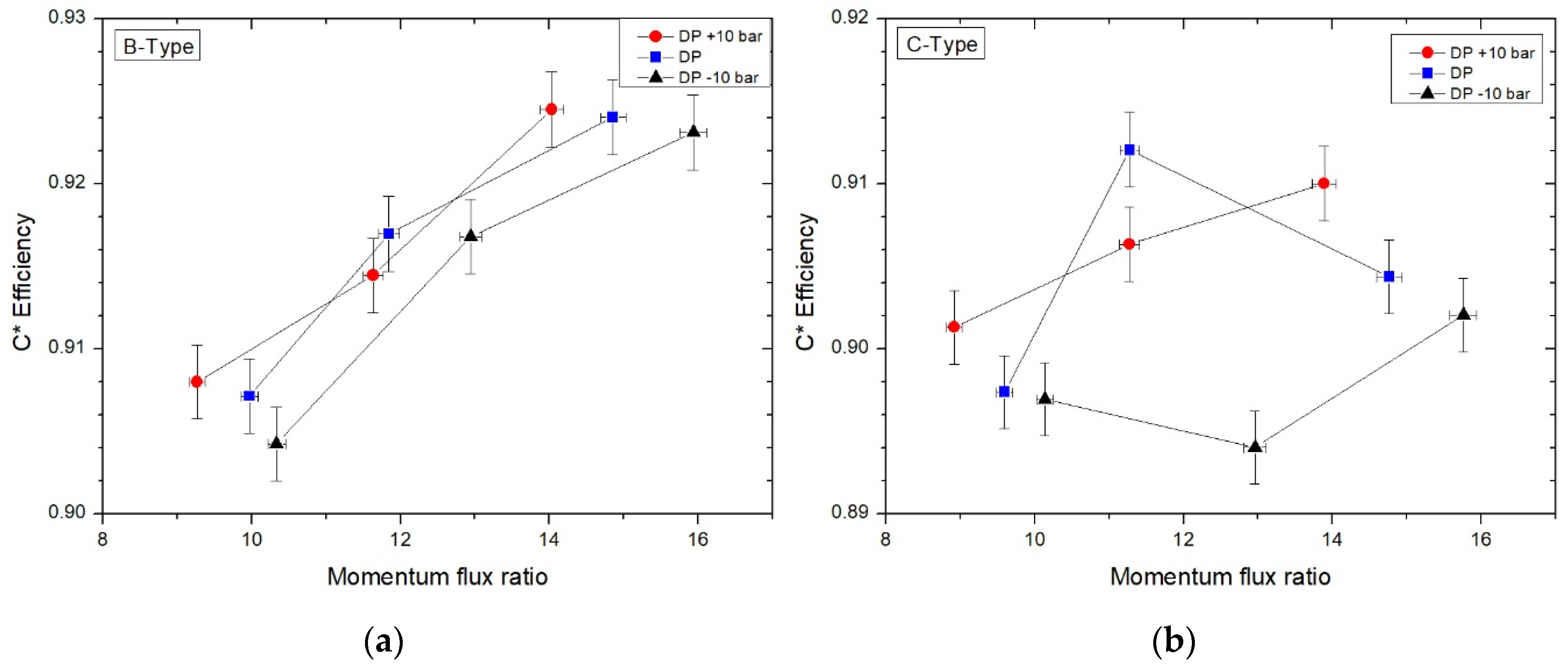
Figure 12 presents the performance efficiency as a function of momentum-flux ratio for each injector. Performance efficiency for the A-type injector averaged 0.934, which is acceptable for a typical engine [
15]. The average efficiency of the B-type injector was 0.915, which was 0.19 lower than that of the A-type, and the average efficiency of the C-type injector was 0.902, which was 0.32 lower than that of the A-type injector. That is, for the A-type and B-type combustors (for which 61 GCSC injectors were applied), it was found that, if the momentum-flux-ratio value increases, the efficiency of the combustion-characteristic velocity also increases. For the C-type combustor with 37 GCSC injectors, the performance efficiency increase was small compared to the test results with 61 GCSC injectors. In terms of performance efficiency, the momentum-flux ratio and performance efficiency are proportional, but the number of injectors seems to affect the increase. The spray-visualization experiment in a high-pressure environment shows that, if the recess ratio is 1, the value of the spray contraction increases until the momentum-flux ratio is 45. The higher the speed of the injected gas, the greater the atomization performance [
8,
9]. Thus, if the diameter of the oxidizer-injection hole of the A-type injector is adjusted to increase the momentum-flux ratio, we expect that the performance efficiency and characteristic velocity will increase as propellant mixing improves until certain limits are reached. Moreover, placing more injectors in the same area on the face plate of the combustor head while reducing their diameters and keeping the momentum-flux ratio constant will also increase the combustion-characteristic velocity.
Heat Flux
Heat flux of the combustion chamber was analyzed by dividing the combustion chamber into three sections to understand the effect of the momentum-flux ratio on the combustion performance efficiency. From the combustor fuel manifold to the first film cooling was the head section, from the first film cooling to the second film cooling was the cylinder section, and from the second film cooling to the combustion nozzle end was the nozzle section. Heat flux of each sections was calculated using the following formula:
where
Cp is the specific heat capacity,
is the flow rate of kerosene flowing into the end of the nozzle, ∆
T is the temperature increase rate of kerosene in each section, and
A is the area inside the combustion chamber [
22,
23,
24].
Figure 13 shows the total heat flux inside the combustion chamber according to the combustion pressure. The A-type has a heat flux value of between 11 and 13
when the combustion pressure is between 81 bar and 89 bar. The B-type indicates heat flux of approximately 10
, 12
under design pressure test conditions of 95 bar, and 13–14
under high-pressure combustion conditions of 105 bar. The C-type has a value between 13 and 16
depending on the mixing ratio in the low pressure combustion condition, 14–19
at the design pressure and 17–19.5
at the high-pressure combustion condition. As the combustion pressure increases, the heat flux increases with a similar slope for all three types of injectors. The C-type injectors had comparatively larger total heat flux values than other types of injectors.
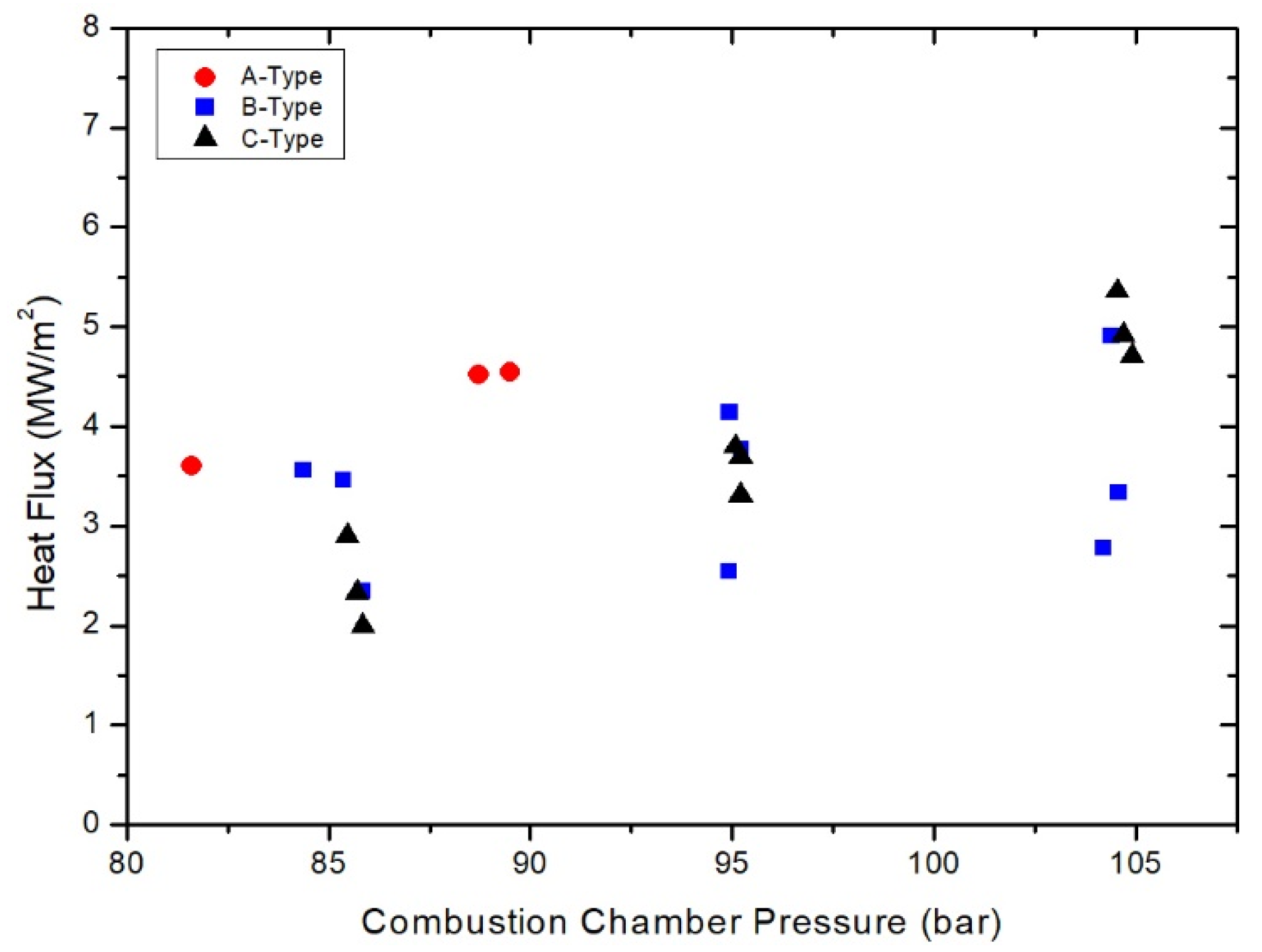
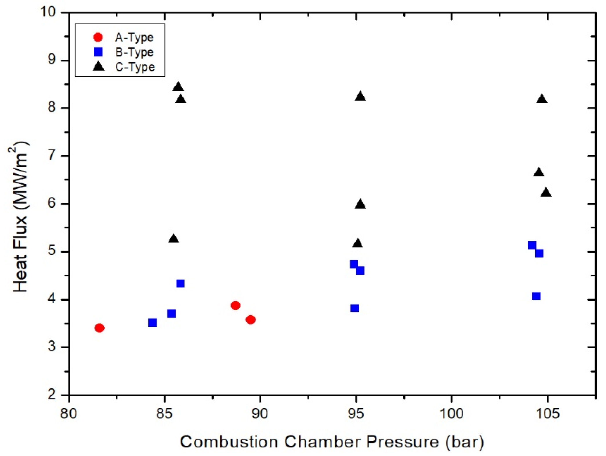
The heat flux for each combustion chamber that was divided into three sections was analyzed and shown in
Figure 14,
Figure 15 and
Figure 16. In the combustion head section, similar to the total heat flux, the heat flux of the C-type shows the highest value and the B-type shows the lowest value. When the combustion pressure is less than 95 bar, the heat flux increases with a slope of about 0.1
bar for all three injectors. In the high-pressure condition where the combustion pressure is around 105 bar, the heat flux value of the C-type decreased, and the difference between the heat flux of the A-type and the B-type decreased to within 1
. In the cylinder section, the higher the combustion pressure for all injector shapes, the greater the heat flux. The heat flux of the A-type is the largest and the heat flux of the B and C types are similar, but the heat flux increase according to the pressure is the largest in the C-type. In the low pressure combustion conditions near 85 bar in the nozzle section, the heat flux of the A and B types is similar within the range of 3–4
, but the C-type is 5–8
, which shows a greater heat flux value compared to other injectors. In the design and low mixture ratio of the C-type injector, as with other injectors, the heat flux also increased with increasing pressure with a constant slope. However, under the high mixture ratio test condition where the momentum-flux ratio is >13, the heat flux of the nozzle section is 8
, which is about twice the value of other injectors. Thus, for the C-type, the heat flux of the nozzle section is higher than the B-type in which the momentum-flux ratio is in a similar range. In particular, in areas with large momentum-flux ratio, sufficient mixing does not occur inside the combustion-chamber cylinder, and the main combustion occurs at the bottom of the cylinder and at the nozzles of the combustor, which appears to reduce combustion efficiency.
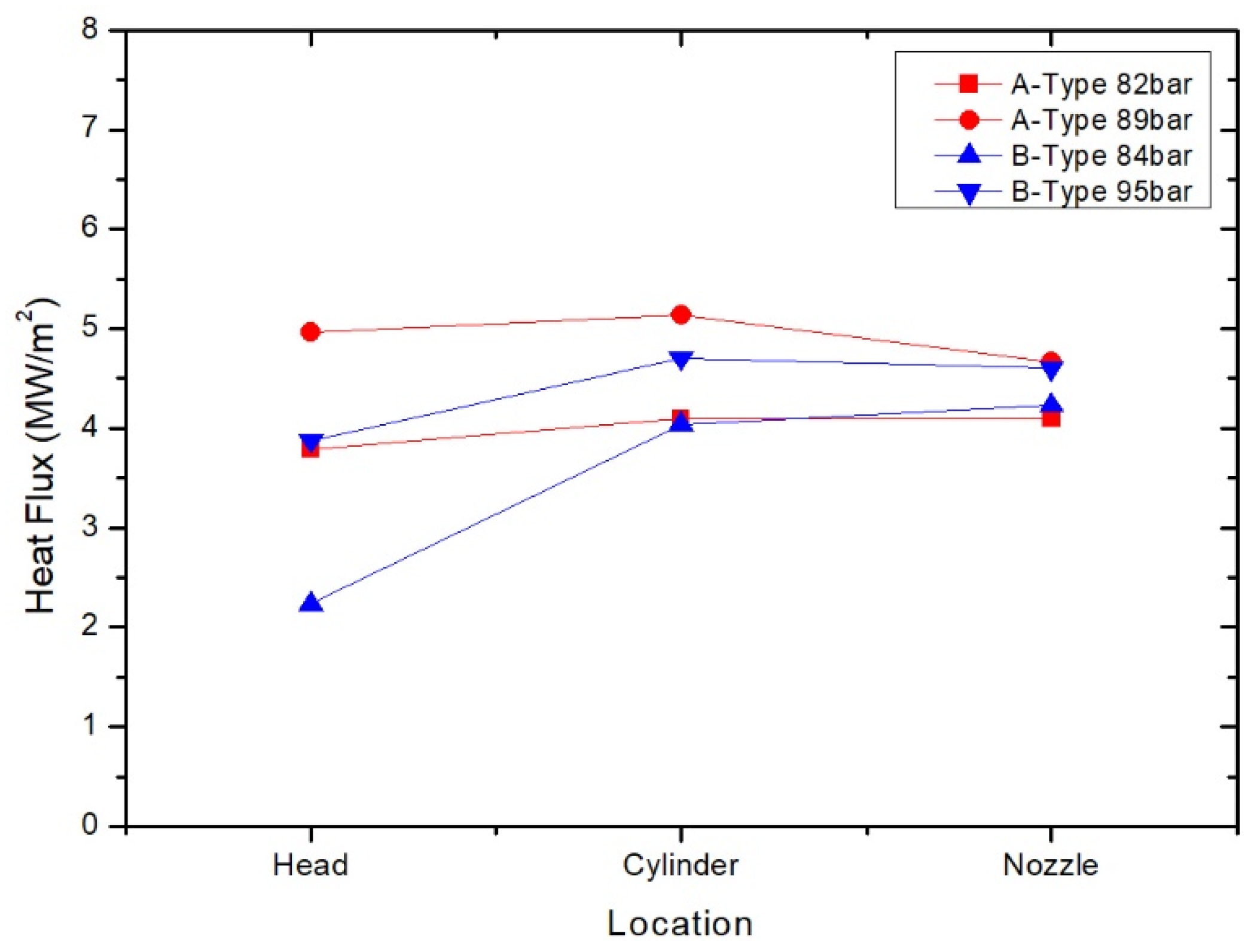
The effect of the momentum-flux ratio on heat flux in the same number of injectors was analyzed by comparing the test results of the B-type under test conditions similar to the low pressure and high mixture ratio conditions in which the A-type experiments were performed (
Figure 17). In the head section, the A-type shows a heat flux value that is about 1–2
larger than the B-type, and the difference is minimized under 0.5
in the cylinder section. Moreover, in the nozzle section, heat flux is equal to 4–5
. The momentum-flux ratio averaged 22 for the A-type and 15 for the B-type, and the combustion-characteristic velocity of the A-type increased by 1.2% compared to the B-type. In other words, as the momentum-flux ratio in the injector increases, efficient mixing and main combustion of propellant is obtained at the injector outlet and top of the combustion-chamber cylinder, thereby increasing the combustion efficiency of the combustor in proportion to the momentum-flux ratio.
4. Conclusions
We compared and analyzed the combustion-characteristic velocities and performance efficiencies of various numbers and diameters of GCSC injectors as functions of the momentum-flux ratio. Our experiments were conducted in a 9-tonf oxidizer-rich staged-combustion-cycle engine. For this purpose, a replaceable combustion chamber was employed. Since the length of the combustion chamber and the flow rate of kerosene used for regenerative cooling were not optimized, we focused on comparing the relative performances of different combustor heads, rather than comparing absolute combustion-characteristic values. For A-type and B-type combustor heads with 61 GCSC injectors, the characteristic velocity and performance efficiency increased proportionally to the momentum-flux ratio with a specific slope. Heat flux analysis shows that the larger the moment flux ratio, the efficient the mixing and combustion of propellant that occurs close to the combustion injector exit, leading to increased combustion efficiency. For all injector types used in this study, the performance efficiency tended to increase along with momentum flux ratio. However, in the case of the same momentum-flux ratio, the efficiency of the propellant mixing reduced in the case of 37 injectors, resulting in the main combustion near the nozzle of the combustion engine, which reduced the characteristic velocity. Hence, to increase the combustion efficiency, it is advantageous to increase the number of injectors per unit area of the combustor’s face plate and to increase each injector’s momentum-flux ratio. We expect that these test results will be used in the future design of GCSC injectors, and applied to the development of 9-tonf oxidizer-rich staged-combustion-cycle engines with injector-optimization designs.


