Article

Limiting Efficiencies of Intermediate Band Solar Cells in Tandem Configuration

School of Electrical, Computer and Energy Engineering, Arizona State University, Tempe, AZ 85287, USA
Energies 2020, 13(22), 6021; https://doi.org/10.3390/en13226021
Submission received: 25 September 2020 / Revised: 13 November 2020 / Accepted: 16 November 2020 / Published: 18 November 2020

Abstract

:
It is necessary to devise innovative techniques to design new high-performance tandem solar cells to meet increasing energy needs. In this study, the theoretical efficiency of intermediate band solar cells (IBSCs) was increased by integrating them with tandem solar cells to produce intermediate band tandem solar cells (IBTSCs). The spectral splitting analysis indicated that the efficient absorption of sub-photon energies was necessary to ensure optimal performance of the IBSCs at each junction of the IBTSC. For this calculation, we assumed all absorption of sub-photon energies are unity. In addition, we applied the variation of absorptivity to the detailed balance limit of a double-junction (DJ) IBTSC. Furthermore, we included the impact of series and shunt resistances of a typical DJ IBTSC to investigate the variations in electrical parameters (short circuit current, open circuit voltage). The performance efficiency also depended on the illumination concentration due to the charge carrier transitions at each junction. We analyzed this aspect to determine the overall performance of the IBTSCs. We replaced the IBSC in the bottom junction with a single-junction solar cell to explore the potential of diverse tandem configurations. DJ IBTSCs achieved a limiting efficiency comparable to that of six-junction solar cells, despite the lower number of junctions. It was challenging for these cells to exhibit optimal performance because of the inefficient spectrum management in the bottom junction. It was concluded that full illumination concentration was required to achieve optimal performance in both junctions of the IBTSC.

1. Introduction

The integration of third-generation photovoltaic (PV) devices into existing solar cell technologies has immense potential to improve the performance of the conventional solar cells. Third-generation PV cells are an emerging class of solar cells to overcome the limit of first (crystalline Si) and second (thin-film) generation PV devices. The target of third-generation PVs is to achieve ultra-high efficiency at a low-cost of electricity (<$0.5/W). Various potential groups have been discussed in order to reach this goal such as perovskite solar cell, dye-sensitized solar cell, organic PVs, and quantum dot solar cells (multiple exciton generation and intermediate band solar cells) [1,2]. Tandem solar cells are well-established PV devices with high conversion efficiencies of over 40% [2,3] as shown by established records [4,5] and theoretical approaches [6,7,8]. Tandem solar cells utilize their many junctions stacked with different bandgap materials to absorb a wide range of photon energy. They can also reduce thermalization losses because of high photon energy absorption in a low-bandgap material. Groups III–V materials are well-suited for tandem solar cells due to minimized lattice mismatches. The recently developed four- and six-junction tandem solar cells have the potential to achieve power conversion efficiencies of more than 50% [9]. However, their performance efficiencies are difficult to improve as the number of junctions increase due to the interface defects between the junctions [10]. Moreover, the issues of lattice mismatch and thermal expansion have to be overcome as the number of junctions increases. Furthermore, their high production cost limits market expansion [11]. Therefore, it is necessary to devise novel concepts for the development of next-generation tandem solar cells.
Intermediate band (IB) solar cells (IBSCs) are PV devices with three optical transitions [12,13] due to the presence of the IBs at the optimal energy levels of the junction. The detailed balance limit (DBL) of IBSC achieves a theoretical efficiency of 63.2% under full illumination (equivalent to 46,200 suns), which is comparable to the performance of a triple-junction tandem solar cell [10,11]. Currently, research is ongoing to ensure that IBSCs continue to match these expectations [14,15]. These efforts toward a better IBSC have been manifested in the multi-stacked quantum dot (QD) (InAs/GaAs QDs) feature and the highly mismatched alloy (GaNAs-based thin film, ZnTeO based thin film) [15]. Moreover, the actual IBSC conversion efficiencies are in the 15~20% range under one sun illumination [15]. The most critical issues of IBSCs are non-radiative recombination and carrier occupancy at IB for efficient optical transitions; these issues reduce the potential efficiency [16]. Therefore, materials and process development will be crucial factors to achieve high efficiency IBSC.
Theoretically, it is possible to produce intermediate band tandem solar cells (IBTSCs) by integrating IBSCs with tandem solar cells. IBTSCs can achieve higher conversion efficiencies with a lower number of junctions as compared to the conventional tandem solar cells [17]. An IBSC behaves like a triple-junction tandem solar cell under concentrated sunlight [17]. The performance of a double-junction (DJ) IBTSC is similar to that of a five- or six-junction tandem PV device, wherein enhanced theoretical efficiencies with fewer junctions and materials are exhibited. These benefits will lead to the replacement of the high number of junctions in tandem solar cells, which will reduce manufacturing costs and lead to increased market size. For this study, we have suggested an optimal material combination for the independent connection of DJ IBTSC in [17]; Ge/Si is used for the bottom junction and InGaN/GaN is used for the top junction [14]. Moreover, the material combinations have been extensively researched for their suitability for IBSCs [18,19]. Therefore, the IBTSC will offer great potential for a high-efficiency tandem solar cell with low production costs if the material systems are well-developed with low or negligible defects and demonstrate excellent carrier occupancy at IB. Furthermore, this research will create many opportunities to achieve high performances of IBTSC by developing high quality nanostructure materials.
The initial studies on the DBL of IBTSCs have inspired the development of novel varieties of tandem solar cell to replace the multilevel IB solar cells [20,21]. The optimization of the IB energy levels within multijunction devices requires spectral splitting [14]. In this study, we discussed the DBLs of IBTSCs by analyzing the solar spectrum splitting of each junction. To explore real-world applicability of the DJ IBTSC, we introduced an absorptivity change in each carrier transition [22] and the single PV model to investigate the impact of series and shunt resistance [23]. Furthermore, we also designed a single-junction (SJ) solar cell in tandem configuration with the IBSC as an alternative to the DJ IBTSC.

2. Theory

In this section, the DBL of DJ IBTSC is presented to explain the theoretical results. First, we present the DBL of DJ IBTSC based on the theory of IBSC and tandem solar cells [6,7,8,12]. Subsequently, we divided two regions of a blackbody radiation spectrum and arranged the order of sub-bandgaps (ECI, EIV and ECV (=Eg)) for each junction of the IBTSC. For this case, we assumed that the absorptivity of each carrier is ideally unity. However, the real-world IBSC has a low conversion efficiency due to low light absorption at the IB region. This can reduce the operating voltage range and experimental efficiency [22]. Thus, we investigated the effect of light absorptivity variation at the IB and bulk region [22]. Next, we considered the series and shunt resistance variations of the DJ IBTSC by a single diode PV model [23,24]. Finally, an alternative DJ IBTSC was suggested by replacing the bottom junction IBSC with a single junction solar cell to efficiently manage the incoming photon energies for each junction.

2.1. Detailed Balance of the Double-Junction Intermediate Band Tandem Solar Cells (DJ IBTSCs)

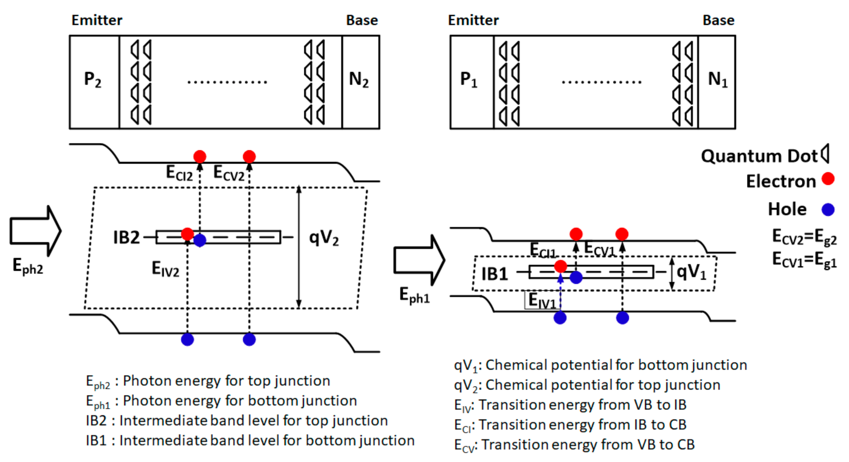
In this section, the operation of the DJ IBTSCs based on the DBL of IBSC and tandem solar cell principles is discussed [11]. In Figure 1, the incoming photon energy (Eph(i)) is selectively absorbed by each junction (ECI(i), EIV(i), and ECV(i) (i = 1, 2), where ECI(i) denotes the energy between the conduction band (CB) and the IB, EIV(i) denotes the energy between the IB and the valence band, and ECV(i) denotes the energy between the CB and the valence band). This enables the generation of a two charge carrier at each junction of the IBTSC for the three possible carrier transitions that are denoted by CI (carrier transition from the CB to the IB), IV (carrier transition from the IB to the valence band (VB)), and CV (carrier transition from the VB to CB).
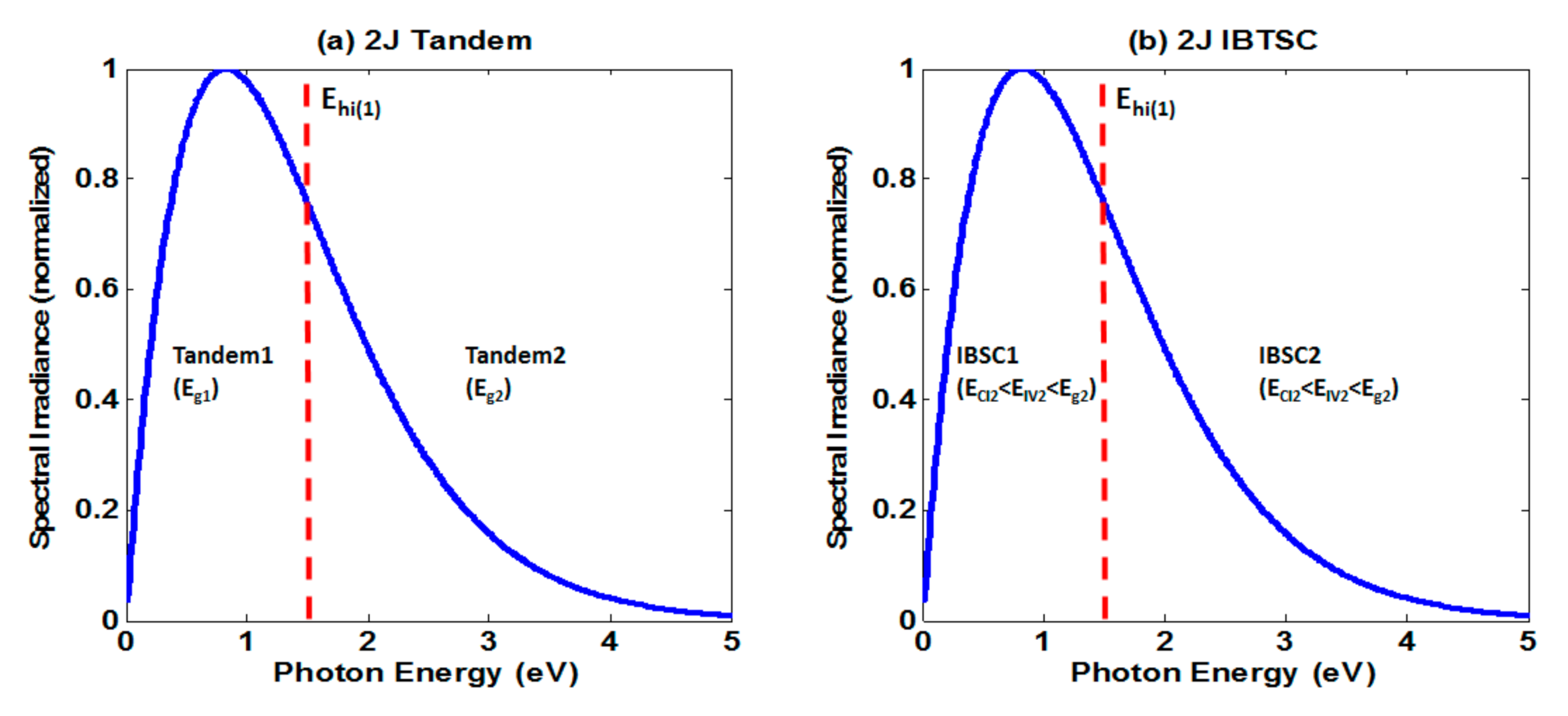
The solar spectrum was split into two regions (Tandem 1 and Tandem 2) for the DJ tandem solar cell operations (Figure 2a). Each stack of the IBSC possessed three different bandgaps (Eg(i), EIV(i), and ECI(i)) that were organized within each region of the spectrum. The lower and upper ranges of the solar spectrum denote the bottom junction (IBSC1) and top junction (IBSC2) of the IBTSC, respectively (Figure 2b).
We introduced Ehi(1) as the boundary point to organize the three sub-bandgaps of each region of the spectrum accurately; thus, we obtained the DBL limits of the IBTSC. The order of the bandgaps of the bottom junction (below Ehi(1)) was ECI1 < EIV1 < Eg1 < Ehi(1) while that of the top junction was ECI2 < EIV2 < Eg2. The overall bandgap sequence was ECI1 < EIV1 < Eg1<Ehi (1) < ECI2 < EIV2 < Eg2. Eg2 had to be three times higher than Eg1 for minimal operations. The detailed balance (DB) relations of the IBTSC are shown in Equations (1)–(5). Equations (1) and (2) show the generation rate and recombination rate, respectively, of the charge carriers in the IBSCs. In these equations the absorptivity was considered in order to describe the potential absorption of each carrier during each carrier transition. We discuss the impact of this in the next section.
G E 2 , E 1 = f S · Conc · 2 π h 3 c 2 E 1 E 2 α E 2 , E 1 · E 2 exp [ E / kT SUN ] 1 dE + 1 f S · Conc · 2 π h 3 c 2 E 1 E 2 α E 2 , E 1 · E 2 exp [ E / kT C ] 1 dE
R E 2 , E 1 = 2 π h 3 c 2 E 1 E 2 α E 2 , E 1 · E 2 exp [ E μ / kT C ] 1 dE
where G is the generation rate, R is the recombination rate, fS is a geometric factor (1/46,200). Conc is the optical concentration (1~46,200), where Conc = 1 and Conc = 46,200 denote 1 sun illumination and full illumination concentration (46,200 suns), respectively; h is the Planck’s constant, c is the speed of light, E1 and E2 are energy states, k is the Boltzmann’s constant (k = 1.38 × 10⁻²³ J/K), TSUN is the temperature of the sun (6000 K), TC is the ambient temperature (300 K), and µ is the chemical potential (q·V, where V is the operating voltage) and αE2,E1 is the absorptivity (0 ≤ αE2,E1 ≤ 1).
The current density (J) of the ith junction in the IBTSC is:
J(i) = q∙(GEhi(i), ECB(i) − REhi(i),ECB(i) + GECB(i),EIB(i) − RECB(i),EIB(i))
where subscript i denotes the number of junctions (i = 1 and 2 denote the bottom and top junctions, respectively), CV denotes the carrier transitions between the VB and CB, and CI denotes the carrier transitions between the IB and CB.
The optimal IB level was determined by the balance of the carrier transitions from (i) VB to IB and (ii) IB to CB. Since the IB was electrically isolated, there were no carrier extractions from the IB. (Equation (4)).
GECB(i), EIB(i) − RECB(i), EIB(i) = GEIB(i), EVB(i) − REIB(i),EVB(i)
The chemical potential of each junction of the IBTSC is:
q∙VCV(i) = q∙VCI(i) + q∙VIV(i)
The equivalent circuit model describes an IBSC as two series-connected diodes possessing bandgaps of ECI and EIV, respectively, that are connected in parallel with a diode possessing a bandgap of ECV. The two series-connected diodes play a significant role in determining the open-circuit voltage (VOC).
The DB relations of each junction are described in Table 1.
The independently connected (Ind) DJ IBTSCs have to satisfy Equation (5) due to the separately calculated maximum power points of each junction. In the series-connected (Ser) IBTSCs, each junction has to satisfy Equation (5) to function as an IBSC.
First of all, the calculated efficiency of Ind is shown Equation (6).
Efficiency   Ind = J 1 V CV 1 · V CV 1 + J 2 V CV 2 · V CV 2 Pin = Conc · f s · σ · T Sun 4   × 100   %
where σ is Stefan–Boltzmann constant (= 5.6704 × 10⁻⁸ W∙m−2∙K−4), J(i) (x) is the current density value at x volt and x is the arbitrary number.
However, the calculated efficiency of Ser DJ IBTSC was similar to that of conventional Ser tandem approaches. The junction with the lowest short circuit current density (JSC) functioned as an IBSC at the optimal value of chemical potential (Equation (5)) and the corresponding current density at the maximum power point (Jm). The corresponding operating voltage (OV) at the other junctions was determined from the value of Jm. The top junction (IBSC2) possessed the lowest JSC (Figure 3); its OV was VCV(2) (=2.78 V), and Jm was 1.466 × 10⁶ mA/cm2. The corresponding OV (V(1) = 0.863 V) of the bottom junction was determined from Jm. Therefore, the overall OV was VCV(2) + V(1). The power was calculated as per the equations provided in Table 2.

2.2. Impact of Absorptivity of Sub-Bandgaps on the DJ IBTSC

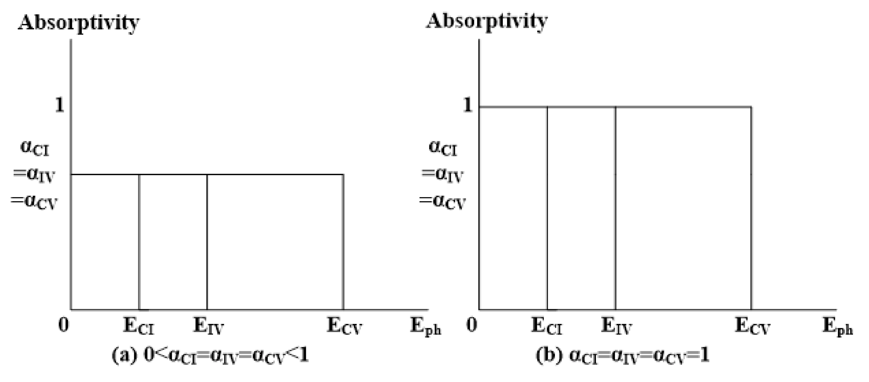
An important assumption in the idealized IBSC is that the incoming light is ideally absorbed into three sub-bandgap energies and upon absorption, each carrier transition is recombined. However, the recombination reduces VOC even if the photo-generated current is enhanced by the IB region. In the actual implementation of the IBSC, the absorptivity of the IB region is low; therefore, it will require enhancement of the photo-generated current by introducing light-concentration, absorptivity improvement, and light trapping [22]. In addition, the light absorptivity (= αCV) of the host material (wide bandgap) must also be assessed based on the entire performance of the IBSC. We present two cases of absorptivity in Figure 4a,b wherein (a) describes the low absorptivity 0 < α < 1 and (b) shows the ideal case of absorptivity (α = 1) of each carrier transition.
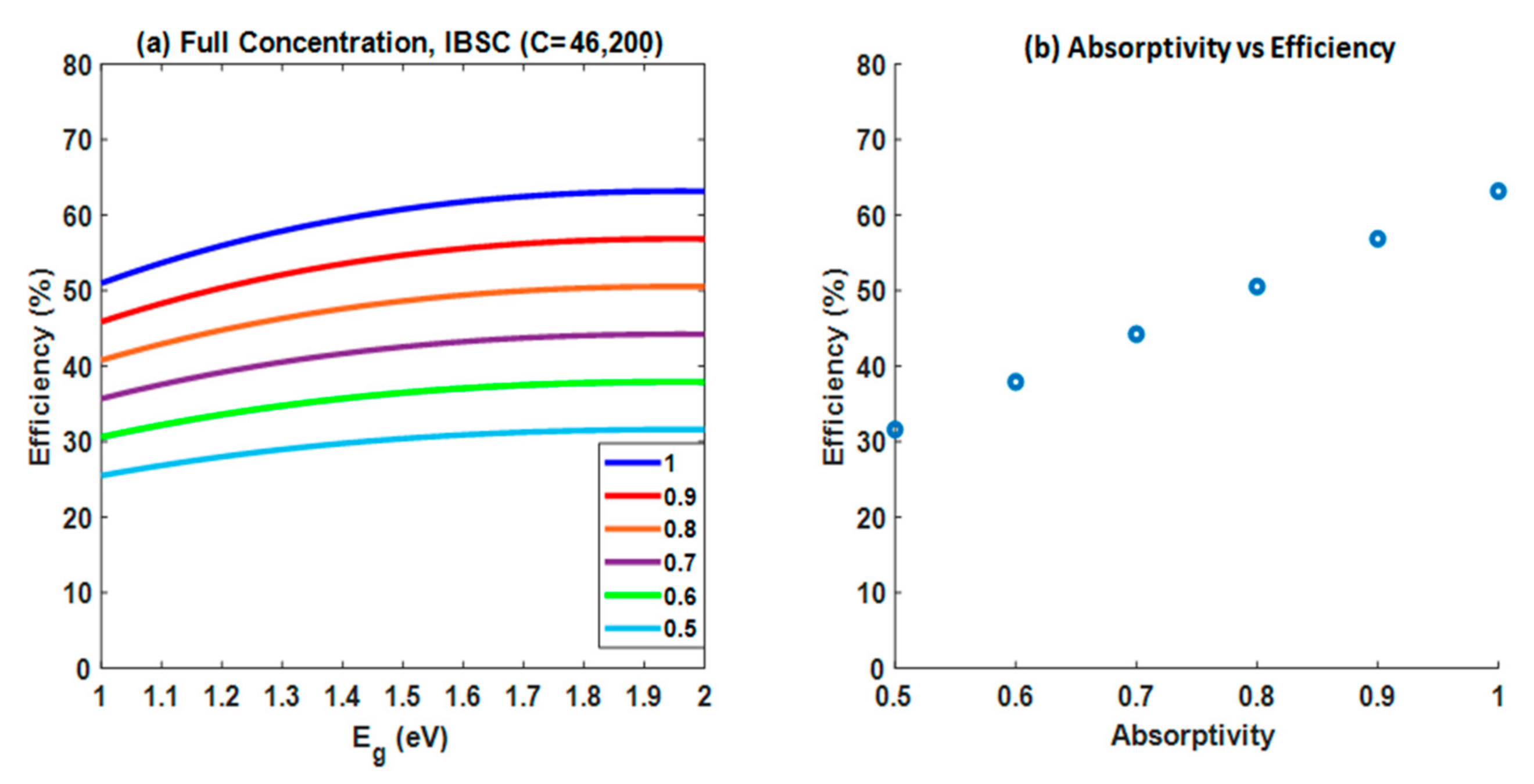
For this calculation, we assume that the absorptivity of each carrier transition is the same (0 ≤ αCI = αIV = αCV ≤ 1) with a non-overlapping spectrum for each region. The related DBL equations are presented in Equations (1)–(5). Further, we used the optimal bandgaps (ECI = 0.72 eV, EIV = 1.25 and ECV = 1.97 eV) at α = αCI = αIV = αCV = 1 to simply explain and compare the variations of absorptivity with the efficiency changes. The results of this calculation are presented in Figure 5a,b.
As show in Figure 5, after applying the absorptivity variation to the DBL of an IBSC, we found that a theoretical maximum efficiency below α = 0.7 is the limit of the single junction (40.8% under blackbody radiation, see Figure 5a,b). In this case, we found (i) the performance of IBSC behaves like a single junction solar cell, and (ii) each carrier transition is not effective due to the low absorption of sub-photon energies. In other words, the role of the IB degrades and ceases to function at α < 0.7 due to the considerable amount of recombination instances at the IB region. Therefore, absorption in IB is crucial to maintaining the performance of IBSC and its minimum absorptivity is 0.7 for efficient light absorption of each carrier transition.

2.3. Detailed Balance Limits (DBLs) of the DJ IBTSC and Impact of Resistance

A real-world tandem solar cell undergoes a change in charge conductivity which has a considerable impact on the series and shunt resistance. Therefore, in this section, we considered the single diode PV model to investigate the impact of series (Rs) and shunt (Rsh) resistance for each carrier transition (ECI, EIV and ECV) in the DBL limit of a DJ IBTSC solar cell [23,24]. Rs is related to carrier collection and current flow between electron and hole contact, metal/semiconductor contact resistance, and metal resistance. Both the material quality and reverse saturation current determine Rsh due to the generation of current leakage current paths which determine the isolation of each junction [23,24]. Under consideration of both resistances in the DJ IBTSC, we investigated the effect on electrical parameters such as JSC and VOC through the analysis of current density and voltage curves.
For the single diode PV model of a solar cell, the related equation is shown in Equations (7) and (8).
J = J ph J 0 exp q · V + JR S KT C V + J · R S R sh
J 0 = 2 π h 3 c 2 E 1 E 2 α E 2 , E 1 · E 2 exp [ E / kT C ] 1 dE
where Rs is the series resistance, Rsh is the shunt resistance, J0 is the reverse saturation current density, Jph is the photo-generated current density, and J is the arbitrary current density.
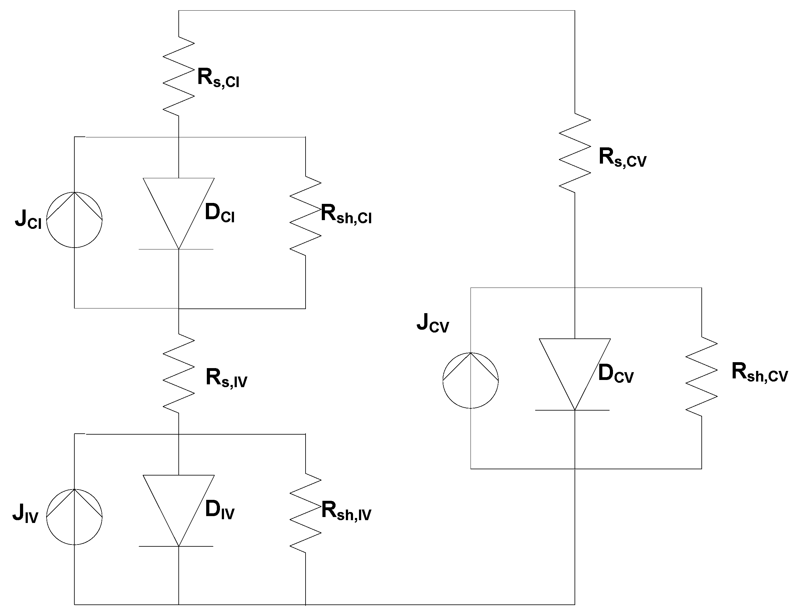
The equivalent circuit model for an IBSC is shown in Figure 6.
Figure 6 describes the PV diode model of each junction in the DJ IBTSC. Furthermore, Equations (7) and (8) are applied to each carrier transition of the three single diode models that are applied into a single junction in the DJ IBTSC. Overall, six diode models are utilized to calculate the resistance impact of DJ IBTSC.
2.4. DBLs of the Single-Junction Intermediate Band Solar Cell (SJ IBSC) with Tandem Configuration

The performance of the bottom junction of the IBTSC was limited by the carrier extractions from VB1 to CB1. In Equation (3), the difference between Ehi(1) and ECV(1) generated an insufficient short circuit current density for the carrier extraction from VB1 to CB1. The current for the carrier transition was significantly lower than that for the normal transition from the VB to CB, where Ehi was infinite. Under one sun illumination, the dominant carrier transition of the bottom junction was (i) VB1 to IB1 and (ii) IB1 to CB1. Hence, its performance nearly resembled that of a DJ series-connected tandem device. The IBSC in the top junction showed optimal performance because the infinite Ehi generated an unlimited JSC. The three available carrier transitions in the top junction ensured that the IBSC performed similarly to a triple-junction tandem solar cell. Therefore, the entire IBTSC performed similarly to a five-junction conventional tandem solar cell. It was difficult to incorporate low-bandgap materials in the bottom junction due to its inefficient spectrum management. Therefore, we replaced the IBSC at the bottom junction with a SJ solar cell. Although the SJ solar cell might face spectrum management issues, it offered flexibility in the choice of materials for the bottom junction. We summarized the DB relations for this configuration in Table 3 and Table 4. The bottom and top junctions of the independently connected DJ hybrid tandem solar cells retained their characteristics. The theoretical performance efficiency of the series-connected tandem device was also similar to that of the conventional tandem devices (see Table 4).
Efficiency   Ind = J 1 V m 1 · V m 1 + J 2 V CV 2 · V CV 2 Pin = Conc · f s · σ · T Sun 4   × 100   %

3. Results

3.1. Dual Junction of Intermediate Band and Tandem Solar Cells

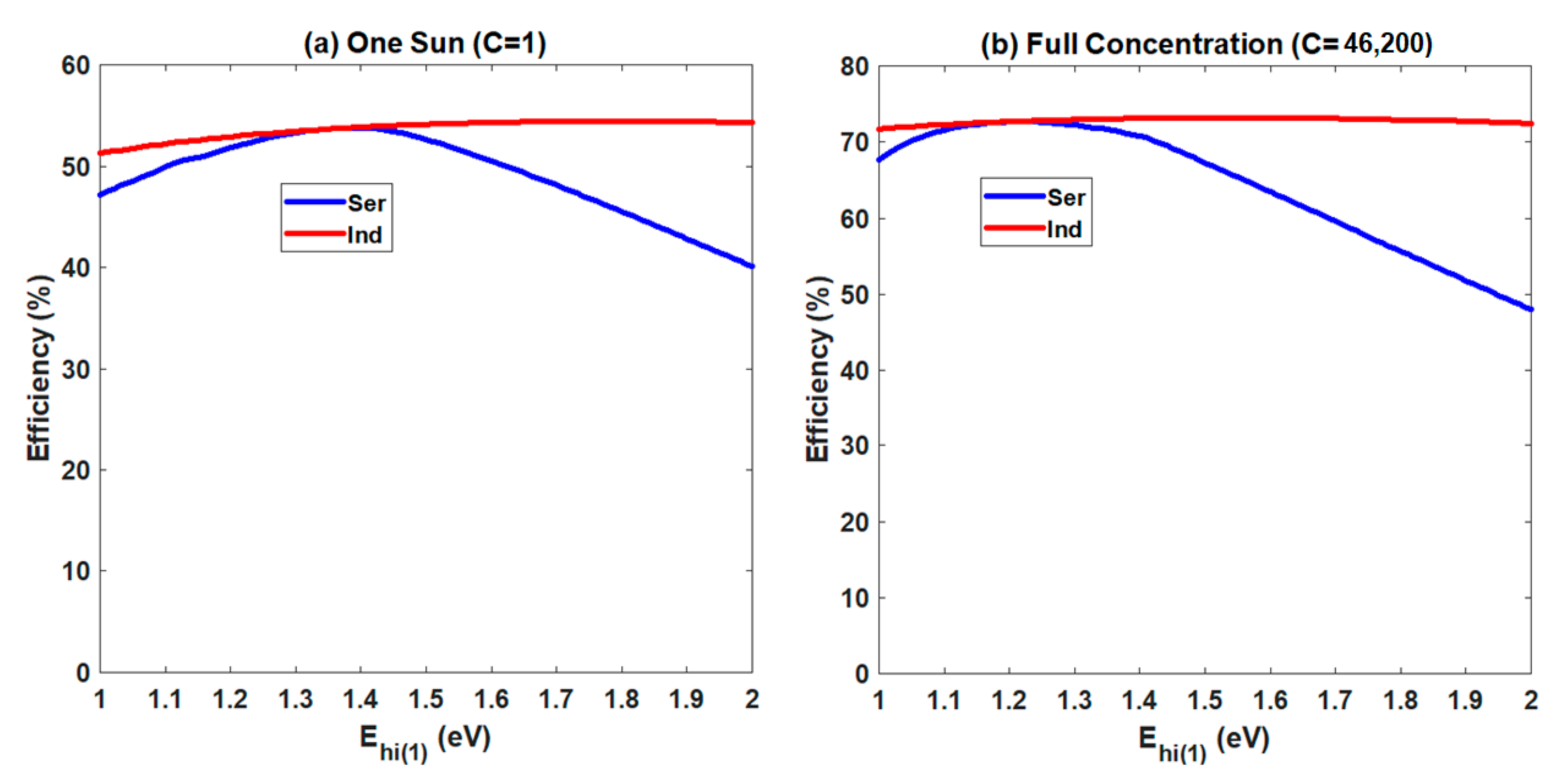
The simulation results of the DJ IBTSC are presented in Figure 7 and Table 5. The data in Table 6 are used to compare the performance efficiencies of the DJ IBTSCs with that of the four, five, and six-junction tandem solar cells. The maximum theoretical conversion efficiencies of the Ind and Ser DJ IBTSCs were 73.2% and 72.7%, respectively, under full illumination (46,200 suns). This was similar to the theoretical conversion efficiency of the six-junction series-connected tandem solar cells (73.4%; see Table 5 and Table 6). Therefore, the Ind and Ser DJ IBTSCs could potentially replace the six-junction tandem solar cells. Under one sun illumination, the overall theoretical efficiencies of the Ind and Ser DJ IBTSCs were similar to that of the four-and five-junction conventional tandem devices. The difference between Ehi (1) (=1.39 eV) and EIV1 (=1.34 eV) in the bottom junction of the Ser DJ IBTSC was 0.05 eV. This slight difference represents the quantity of energy needed for full extraction of the carrier from VB1 to CB1. Hence, the bottom junction of the DJ IBTSC performed similarly to a DJ series-connected tandem solar cell possessing bandgaps of ECI1 and EIV1. Therefore, the bottom junction of a DJ IBTSC was not an optimally performing IBSC under one sun illumination.
Figure 8 shows the current density–voltage curves for the bottom and top junctions of a DJ IBTSC under one sun illumination (Conc = 1) and full-light concentration (Conc = 46,200). JSC for ECV1 is 2.45 mA/cm2 under one sun illumination (Figure 8a). The transition from VB1 to CB1 in the bottom junction was not robust due to the slight difference between ECV1 (1.34 eV) and Ehi(1) (1.39 eV) that arose due to spectral splitting (Equation (3)). Two carrier transitions ((1) VB1 to IB1, and (2) IB1 to CB1) were dominant in the bottom junction because the magnitude of the photocurrent for the carrier extraction from VB1 to CB1 was low. Therefore, the bottom junction of the IBTSC operated similarly to a series-connected DJ tandem solar cell under one sun illumination. The top junction operated like a conventional IBSC (Figure 8b) since the infinite Ehi ensured that there were no limits for the carrier extraction. The theoretical efficiency of the DJ IBTSC under one sun illumination was similar to that of four- or five-junction conventional tandem solar cells.
The JSC of ECV1 was 7.17 × 10⁵ mA/cm2 under full-light concentration (Figure 8c,d). Although the JSC of ECV1 was limited by the spectral splitting, the fully concentrated illumination increased the difference between Ehi(1) and ECV1 (Ehi(1) − ECV1 = 0.275 eV). It could help to increase JSC of ECV1.
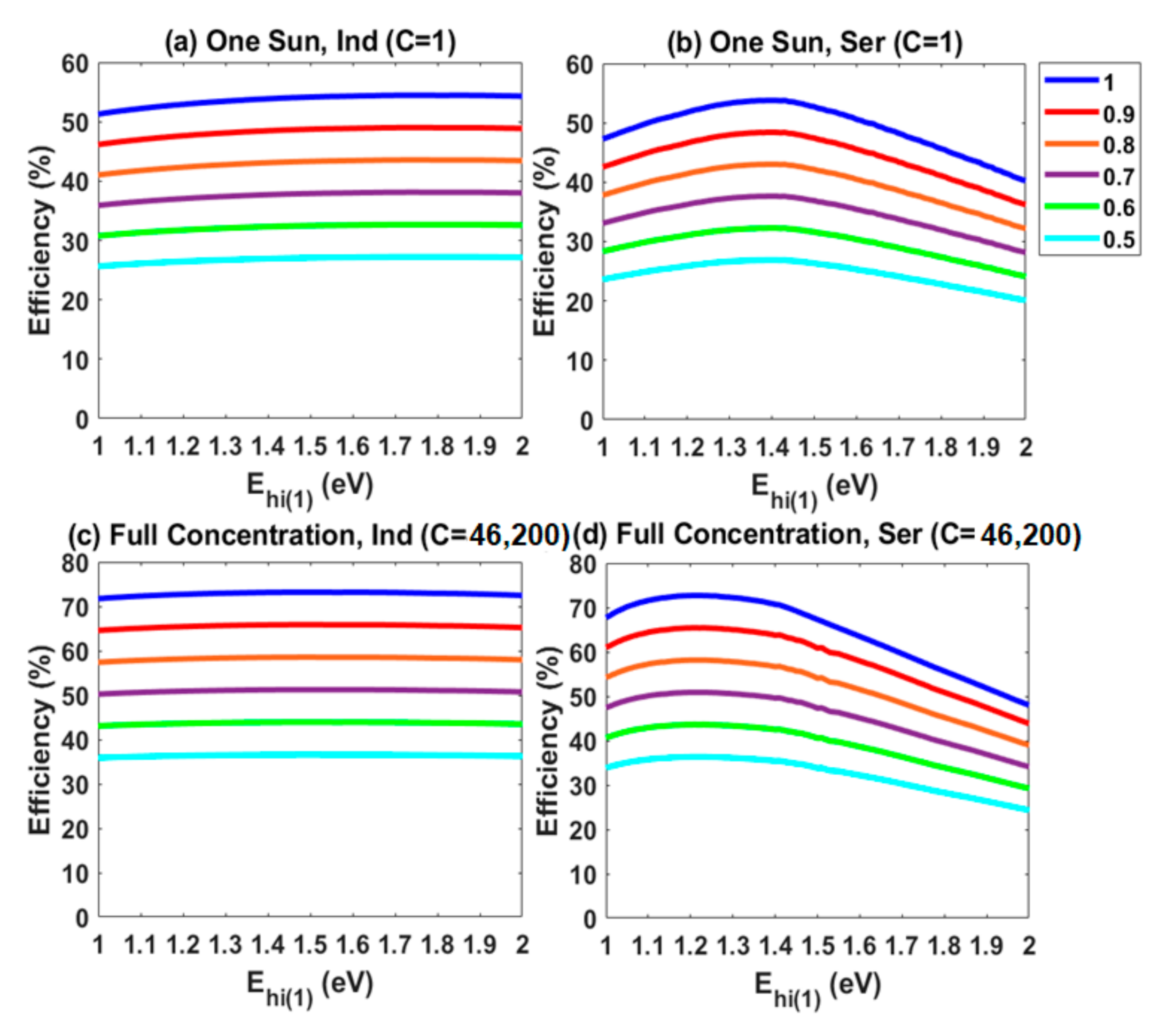
Furthermore, we included the effect of absorptivity of each carrier transition in the DJ IBTSC. For this simulation, we set the range of absorptivity from 0.5~1 to investigate the impact for sub-photon energy absorption. In the one sun illumination case (see Figure 9a,b), the overall performance of IBSC began to decline below 0.6 of α such that the role of IB in the DJ IBTSC became negligible due to weak transition of each carrier from the low absorptivity. In Figure 9c,d it can be observed that the theoretical efficiency of the DJ IBTSC (Ind and Ser) under full-light concentration (C = 46,200) was similar to the single junction limit at α < 0.7. In other words, the application of concentrated illumination can improve the quality of the IB region for effective absorption of the sub-photon energies.

3.2. The Resistance Impact of the DJ IBTSC

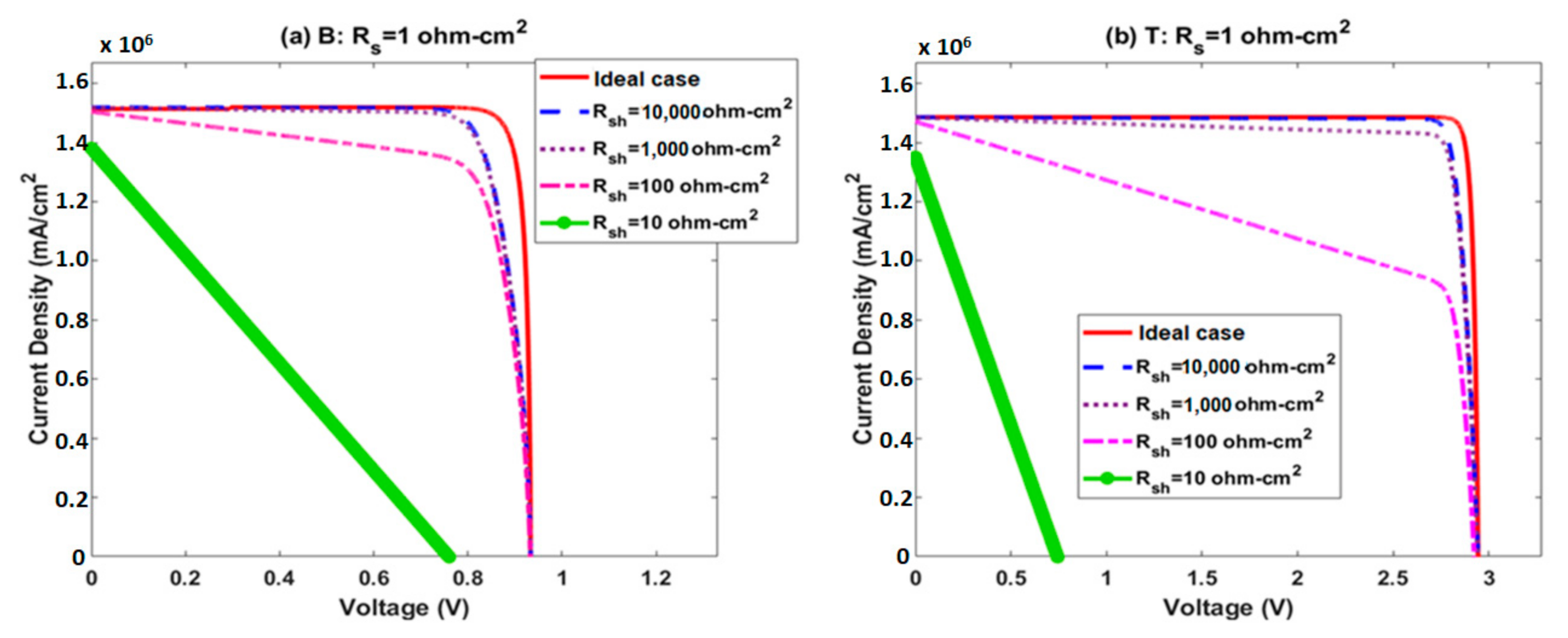
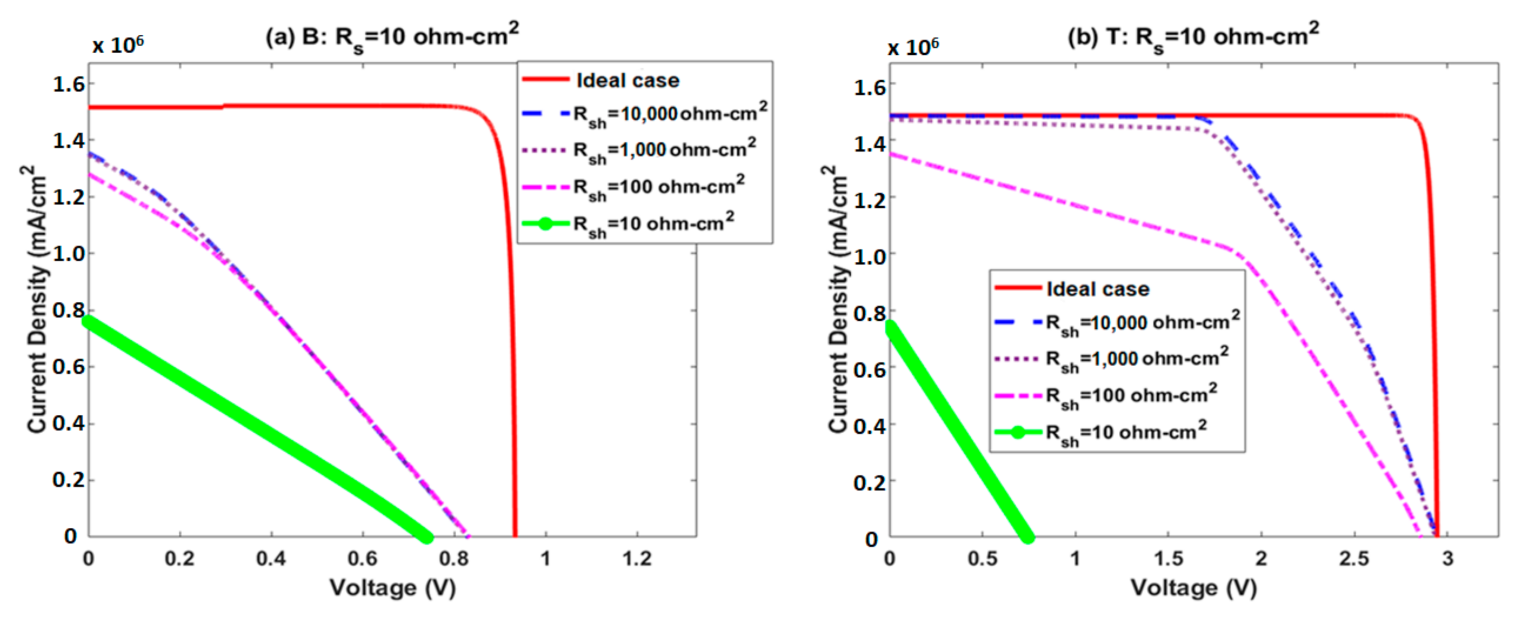
In consideration of the resistance impact of the DJ IBTSC, we included the single diode PV model for each carrier transition and set the resistance value for Rs = 1 Ω-cm2 and 10 Ω-cm2 with the variations of Rsh (10,000, 1000 and 100 and 10 Ω-cm2). For this simulation, we use the optimal bandgap results for Ser DJ IBTSC under full-illumination concentration. The results are summarized in Figure 10 and Figure 11 and Table 7. First, we compared 1 Ω-cm2 with the ideal case of IBTSC and Rsh variations to discuss the actual case of IBTSC. In the case with low Rs (=1 Ω-cm2) with a moderate range of Rsh (1000~10,000 Ω-cm2), the loss of electrical parameters of each junction were relatively small and its corresponding efficiency ranges were over 67%, which is higher than that of IBSC (63.2%) (see Figure 10a,b, Table 7). However, the large fill factor losses show that below 100 Ω-cm2 it could not maintain full IBSC properties for each junction due to the large VOC reduction at each junction. In other words, minimizing the current leakage paths is key to maintaining full IBSC function at each junction. In the case of high series-resistance (see Figure 11a,b), the bottom junction undergoes huge efficiency losses (see Figure 11a) even if it has a moderate shunt resistance range and the top junction undergoes significant efficiency. Typically, the considerable JSC and VOC losses of the bottom junction are due to low carrier collections at the contact and absorbing spectrum limit (see Figure 2b and Figure 11a). For instance, (i) JSC,ideal (=1.51 × 10⁶ mA/cm2) is larger than JSC,actual (≤ 1.34 × 10⁶ mA/cm2) and (ii) VOC,ideal =0.935 V is larger than VOC,actual ≤ 0.825 V due to the relatively small margin of light-absorption (=Ehi(1) – Eg1 = 0.275 eV) and Rsh. Compared to Rs = 1 Ω-cm2 case, the loss of VOC in Rs = 10 Ω-cm2 is significantly larger than that in Rs = 1 Ω-cm2 case. Thus, the carrier collection of the bottom junction is a significant factor in the DJ IBTSC operation. Moreover, the generation of current leakage paths means that the material quality is a significant factor for IBSC performance maintenance. In Table 7, we do not calculate the theoretical efficiency for Rs = 10 Ω-cm2 due to large fill-factor losses of the bottom and top junctions. Thus, typically, the performance of the bottom junction is crucial due to the rapid degradation of the overall DJ IBTSC performance with decreasing Rsh.

3.3. SJ in Tandem Configuration with an IBSC

We considered another method for tandem configuration of IBSCs to address the limited performance efficiency of the bottom junction of DJ IBTSCs. We replaced the IBSC in the bottom junction with a SJ device to manage the incoming photon energy. The overall theoretical efficiencies were similar to that of four-junction conventional tandem solar cells. (Table 6 and Table 8; Figure 12). Under one sun illumination (Conc = 1), the theoretical efficiencies were 1–2% lower than that of the conventional four-junction tandem solar cells due to the inefficient spectrum management at the bottom junction. The optimal bandgaps and maximum efficiencies of the Ser DJ IBTSCs were similar to that of Ind DJ IBTSCs, under one sun illumination. This offered flexibility to use either the Ser or the Ind DJ IBTSCs for cell configuration with the same materials. The overall theoretical efficiencies under fully concentrated illumination were similar to those of conventional four-junction tandem solar cells.

4. Conclusions

The integration of third-generation PV devices into tandem solar cells can potentially quicken the development of new generation tandem solar cells. The limitations of the conventional tandem solar cells were overcome by reaching the DB limits in DJ IBTSCs. The overall theoretical efficiency of DJ IBTSCs under full illumination was similar to that of six-junction tandem solar cells despite the lower number of junctions. This was caused by the three available carrier transitions in each junction of the IBTSC. While considering the spectral splitting of DJ IBTSCs, we also determined the sequence of the three sub-bandgaps for the carrier transitions in each junction. The bottom junction of the Ser IBTSCs did not function at the optimal level under one sun illumination due to the negligible photocurrent for the carrier transition from the VB to the CB transition. Therefore, full illumination was needed to achieve optimal performance in both junctions of the DJ IBTSCs.
Furthermore, we introduced the impact of non-idealities of the DJ IBSC by including (i) absorptivity variation of each carrier transition and (ii) Rs and Rsh into the DJ IBTSC PV model. We observed that (i) the minimum absorptivity for the DJ IBTSC is 0.6~0.7 for overcoming conventional tandem limit due to improvement of carrier absorption and reduced recombination and (ii) the role of the bottom junction is important for the full operation of DJ IBTSC while minimizing the loss of JSC and VOC by introducing Rs and Rsh.
We also substituted the IBSC of the bottom junction with a SJ solar cell due to the inefficient spectrum management of the bottom junction of the IBTSC. This hybrid approach yielded a performance efficiency that was comparable to that of four-junction conventional tandem solar cells. The performance efficiencies of both the Ser and Ind IBTSCs under one sun illumination were similar; this offered flexibility to use either IBTSC without any change in the optimal materials or the material combination.

Author Contributions

Conceptualization, J.L.; methodology, J.L; writing—original draft preparation, J.L.; writing—review and editing, J.L. All authors have read and agreed to the published version of the manuscript.

Funding

This research received no external funding.

Conflicts of Interest

The authors declare no conflict of interest.

References

  1. Conibeer, G. Third-generation photovoltaics. Mater. Today 2007, 10, 42–50. [Google Scholar] [CrossRef]
  2. Green, M.A. Third generation photovoltaics: Ultra-high conversion efficiency at low cost. Prog. Photovolt. Res. Appl. 2001, 9, 123–135. [Google Scholar] [CrossRef]
  3. Yamaguchi, M.; Takamoto, T.; Araki, K.; Imaizumi, M.; Kojima, N.; Ohshita, Y. Present and Future of High Efficiency Multi-Junction Solar Cells. In Proceedings of the Conference on Lasers and Electro-Optics, Baltimore, MD, USA, 1–6 May 2011; pp. 1–3. [Google Scholar]
  4. Bett, A.W.; Philipps, S.P.; Essig, S.; Heckelmann, S.; Kellenbenz, R.; Klinger, V.; Niemeyer, M.; Lackner, D.; Dimroth, F. Overview about technology perspectives for high efficiency solar cells for space and terrestrial applications. In Proceedings of the 28th European Photovoltaic Solar Energy Conference and Exhibition, Paris, France, 30 September–4 October 2013. [Google Scholar]
  5. Geisz, J.F.; Steiner, M.A.; Jain, N.; Schulte, N.K.L.; France, R.M.; McMahon, W.E.; Perl, E.E.; Friedman, D.J. Building a Six-Junction Inverted Metamorphic Concentrator Solar Cell. IEEE J. Photovolt. 2018, 8, 626–632. [Google Scholar] [CrossRef]
  6. Brown, A.S.; Green, M.A. Detailed balance limit for the series constrained two terminal tandem solar cell. Phys. E Low Dimens. Syst. Nanostructures 2002, 14, 96–100. [Google Scholar] [CrossRef]
  7. Martí, A.; Araújo, G.L. Limiting efficiencies for photovoltaic energy conversion in multigap systems. Sol. Energy Mater. Sol. Cells 1996, 43, 203–222. [Google Scholar] [CrossRef]
  8. Bremner, S.P.; Levy, M.Y.; Honsberg, C.B. Analysis of tandem solar cell efficiencies under AM1.5G spectrum using a rapid flux calculation method. Prog. Photovolt. Res. Appl. 2008, 16, 225–233. [Google Scholar] [CrossRef]
  9. Green, M.A.; Dunlop, E.D.; Hohl-Ebinger, J.; Yoshita, M.; Kopidakis, N.; Hao, X. Solar cell efficiency tables (version 56). Prog. Photovolt. Res. Appl. 2020, 28, 629–638. [Google Scholar] [CrossRef]
  10. Yamaguchi, M.; Takamoto, T.; Araki, K.; Ekins-Daukes, N. Multi-junction III–V solar cells: Current status and future potential. Sol. Energy 2005, 79, 78–85. [Google Scholar] [CrossRef]
  11. Yamaguchi, M.; Lee, K.-H.; Araki, K.; Kojima, N. A review of recent progress in heterogeneous silicon tandem solar cells. J. Phys. D Appl. Phys. 2018, 51, 133002. [Google Scholar] [CrossRef]
  12. Luque, A.; Martí, A. Increasing the Efficiency of Ideal Solar Cells by Photon Induced Transitions at Intermediate Levels. Phys. Rev. Lett. 1997, 78, 5014–5017. [Google Scholar] [CrossRef]
  13. Luque, A.; Marti, A.; Stanley, C.R.; López, N.; Cuadra, L.; Zhou, D.; Pearson, J.L.; McKee, A.C. General equivalent circuit for intermediate band devices: Potentials, currents and electroluminescence. J. Appl. Phys. 2004, 96, 903–909. [Google Scholar] [CrossRef]
  14. Ban, K.-Y.; Bremner, S.P.; Liu, G.; Dahal, S.N.; Dippo, P.C.; Norman, A.G.; Honsberg, C.B. Use of a GaAsSb buffer layer for the formation of small, uniform, and dense InAs quantum dots. Appl. Phys. Lett. 2010, 96, 183101. [Google Scholar] [CrossRef]
  15. Dahal, S.N.; Bremner, S.P.; Honsberg, C.B. Identification of candidate material systems for quantum dot solar cells including the effect of strain. Prog. Photovolt. Res. Appl. 2010, 18, 233–239. [Google Scholar] [CrossRef]
  16. Okada, Y.; Ekins-Daukes, N.; Kita, T.; Tamaki, R.; Yoshida, M.; Pusch, A.; Hess, O.; Phillips, C.C.; Farrell, D.J.; Ahsan, N.; et al. Intermediate band solar cells: Recent progress and future directions. Appl. Phys. Rev. 2015, 2, 021302. [Google Scholar] [CrossRef] [Green Version]
  17. Lee, J.; Honsberg, C.B. The thermodynamic limits of tandem photovoltaic devices with intermediate band. Proc. SPIE 2012, 8256, 82560Q. [Google Scholar] [CrossRef]
  18. Tsai, Y.-C.; Lee, M.-Y.; Li, Y.; Samukawa, S. Design and Simulation of Intermediate Band Solar Cell with Ultradense Type-II Multilayer Ge/Si Quantum Dot Superlattice. IEEE Trans. Electron Devices 2017, 64, 4547–4553. [Google Scholar] [CrossRef]
  19. Sang, L.; Liao, M.; Liang, Q.; Takeguchi, M.; Dierre, B.; Shen, B.; Sekiguchi, T.; Koide, Y.; Sumiya, M. A Multilevel Intermediate-Band Solar Cell by InGaN/GaN Quantum Dots with a Strain-Modulated Structure. Adv. Mater. 2013, 26, 1414–1420. [Google Scholar] [CrossRef]
  20. Antolín, E.; Martí, A.; Luque, A. Energy conversion efficiency limit of series connected intermediate band solar cells. In Proceedings of the 21st European Photovoltaic Solar Energy Conference, Dresden, Germany, 4–8 September 2006; pp. 412–415. [Google Scholar]
  21. Luque, A. Will we exceed 50% efficiency in photovoltaics? J. Appl. Phys. 2011, 110, 031301. [Google Scholar] [CrossRef]
  22. Pusch, A.; Yoshida, M.; Hylton, N.; Mellor, A.; Phillips, C.C.; Hess, O.; Ekins-Daukes, N.J. Limiting efficiencies for intermediate band solar cells with partial absorptivity: The case for a quantum ratchet. Prog. Photovolt. Res. Appl. 2016, 24, 656–662. [Google Scholar] [CrossRef] [Green Version]
  23. Cotfas, D.T.; Cotfas, P.A.; Kaplanis, S. Methods to determine the dc parameters of solar cells: A critical review. Renew. Sustain. Energy Rev. 2013, 28, 588–596. [Google Scholar] [CrossRef]
  24. Sabadus, A.; Mihailetchi, V.; Paulescu, M. Parameters extraction for the one-diode model of a solar cell. AIP Conf. Proc. 2017, 1916, 040005. [Google Scholar]
Figure 1. Schematic of a double-junction (DJ) intermediate-band tandem solar cell (IBTSC). 1 and 2 denote the bottom and top junctions, respectively. Eph1 and Eph2 are the photon energies for the bottom and top junctions, respectively.
Energies 13 06021 g001
Figure 2. Spectral splitting of the two regions in a DJ IBTSC. Ehi(1) (1.5 eV) is the boundary photon energy for an independently connected DJ IBTSC at maximum conversion efficiency.
Energies 13 06021 g002
Figure 3. Current density-voltage relationship between the top and bottom junctions of the IBTSC. Intermediate band solar cell IBSC2 (top junction) has the lowest short circuit current density (JSC), and the current density at the maximum power point is Jm. The corresponding voltage of IBSC2 at the optimum point is VCV(2). For the same value of Jm at IBSC1, the corresponding voltage is V(1).
Energies 13 06021 g003
Figure 4. The absorptivity variation. (a) illustrates the partially absorbed incoming sub-bandgap photon energies and (b) shows the ideal absorption of incoming sub-photon energies.
Energies 13 06021 g004
Figure 5. The IBSC efficiency distribution with changing absorptivity (0.5~1). The same optimal bandgaps were used for an IBSC under full-light concentration (C = 46,200) (a) is the calculated efficiencies vs. bandgap energy (host material) with variation of absorptivity. (b) is the maximum calculated efficiency with absorptivity changes.
Energies 13 06021 g005
Figure 6. The equivalent circuit model of one junction for IBSC with consideration of series and shunt resistance for each carrier transition.
Energies 13 06021 g006
Figure 7. Simulation results of independently connected (Ind) and series-connected (Ser) DJ IBTSCs under one sun illumination (Conc = 1) and full illumination (Conc = 46,200).
Energies 13 06021 g007
Figure 8. Current density (J)−voltage (V) curve of a series-connected DJ IBTSC. For C = 1, (a) bottom junction and (b) top junction; for C = 46,200, (c) bottom junction and (d) top junction.).
Energies 13 06021 g008
Figure 9. The theoretical variations of efficiency with changing absorptivity and light concentration variations (α = 0.5, 0.6, 0.7, 0.8, 0.9, 1, Conc = 1 for Figure 9a and 46,200 for Figure 9b).
Energies 13 06021 g009
Figure 10. The current density and voltage curve of series-connected DJ IBTSC with Rs = 1 Ω-cm2 under full-light concentration (C = 46,200) where B is the bottom junction and T is the top junction.
Energies 13 06021 g010
Figure 11. The current density and voltage curve of series-connected dual junction IBTSC with Rs = 10 Ω-cm2 under full-light concentration (C = 46,200) where B is the bottom junction and T is the top junction
Energies 13 06021 g011
Figure 12. Simulation results for series-connected and independently connected DJ IBTSCs comprising an SJ device as the bottom junction and an IBSC as the top junction. (a) represents one sun illumination (Conc = 1) and (b) represents full concentration (Conc = 46,200).
Energies 13 06021 g012
Table 1. Detailed balance (DB) equations for a DJ IBTSC where i = 1 and 2 for the bottom and top junctions, respectively.
DB EquationBottom JunctionTop Junction
Current DensityJ(1) = q∙(GEhi(1),ECB(1) − REhi(1),ECB(1) + GECB(1),EIB(1) − RECB(1),EIB(1))J(2) = q∙(GEhi(2),ECB(2) − REhi(2),ECB(2) + GECB(2),EIB(2) − RECB(2),EIB(2))
IB levelGECB(1),EIB(1) − RECB(1),EIB(1) = GEIB(1),EVB(1) − REIB(1),EVB(1)GECB(2),EIB(2) − RECB(2),EIB(2) = GEIB(2),EVB(2) − REIB(2),EVB(2)
Chemical Potentialq∙VCV(1) = q∙VCI(1) + q∙VIV(1)q∙VCV(2) = q∙VCI(2) + q∙VIV(2)
Table 2. Theoretical approaches to calculate the power of DJ series-connected IBTSCs, where Jm is the current density of the bottom or top junction at the point of maximum power. At the same value of Jm, V(1) and V(2) are the corresponding voltages of the bottom and top junctions, respectively.
The Lowest Short Current Density at Bottom JunctionThe Lowest Short Current Density at Top Junction
Power = Jm∙(VCV(1) + V(2)) Power = Jm∙(V(1) + VCV(2))
Efficiency (Ser) = Power/Pin × 100 (%)
Table 3. DB equations of a DJ IBTSC with a single-junction (SJ) solar cell as the bottom junction and an IBSC as the top junction.
Bottom JunctionTop Junction
Current DensityJ(1) = q∙(GEhi1(1),ECB(1) − REhi1(1),ECB(1))J(2) = q∙(GEhi1(2),ECB(2) – REhi(2),ECB(2) + GECB(2),EIB(2) – RECB(2),EIB(2))
IB levelN/AGE CB(2), E IB(2) – RE CB(2), E IB(2) = GE IB(2), E VB(2) – RE IB(2), EVB(2)
Chemical Potentialq∙Vm(1) at the maximum power pointq∙VCV(2) = q∙VCI(2) + q∙VIV(2)
Table 4. Theoretical approaches to calculate the power of DJ series-connected IBTSCs where a SJ solar cell is the bottom junction and an IBSC is the top junction. Jm is the current density of the bottom and top junction at the point of maximum power. At the same value of Jm, V(1) and V(2) are the corresponding voltages of the bottom and top junctions, respectively. Vm(1) is the voltage at the point of maximum power of the bottom junction.
The Lowest Shirt Current Density at Bottom JunctionThe Lowest Shirt Current Density at the Top Junction
Power = Jm∙(Vm(1) + V(2)) Power = Jm∙(V(1) + VCV(2))
Efficiency (Ser) = Power/Pin × 100 (%)
Table 5. Optimal bandgaps and maximum efficiency (η) of independently connected (Ind) and series-connected (Ser) DJ IBTSCs under blackbody radiation, where concentration (Conc) is 1 or 46,200 suns.
Conc ECI1 (eV)EIV1 (eV)Eg1 (eV)ECI2 (eV)EIV2 (eV)Eg2 (eV)η (%)
1I0.5251.0151.5401.7402.2904.03054.4
S0.4450.8951.3401.3901.9553.34553.8
46,200I0.3490.7511.1101.5002.0603.56073.2
S0.2950.640.9351.2101.7702.98072.7
Table 6. Optimal bandgaps and maximum efficiency (η) of a four-, five-, and six-junction tandem solar cell under blackbody radiation, where concentration (Conc) is 1 or 46,200 suns.
Number of JunctionConc Eg1 (eV)Eg2 (eV)Eg3 (eV)Eg4 (eV)Eg5 (eV)Eg6 (eV)η (%)
41I0.721.211.772.55 53.3
S0.721.101.532.14 52.5
446,200I0.521.031.612.41 68.8
S0.510.941.392.02 67.9
51I0.661.071.502.032.79 56.0
S0.660.971.301.702.29 55.1
546,200I0.450.881.341.882.66 72.0
S0.440.811.161.582.18 71.1
61I0.610.961.331.742.263.0058.0
S0.610.891.161.461.842.4257.0
646,200I0.400.781.161.592.112.8674.4
S0.370.701.001.321.712.3073.4
Table 7. Theoretical efficiency with Rs and Rsh variation for the DJ IBTSC under full-light concentration.
Rs1 Ω-cm210 Ω-cm2
Rsh
Ideal case72.7 %72.7%
10,00067.8 %N/A
100067.4 %N/A
10056.4 %N/A
1021.6 %N/A
Table 8. Optimal bandgaps and maximum efficiency (η) of independent (Ind) and series (Ser) connected DJ IBTSCs with a SJ solar cell as the bottom junction under blackbody radiation, where concentration (Conc) is 1 or 46,200 suns.
Conc Eg1 (eV)ECI2 (eV)EIV2 (eV)Eg2 (eV)η (%)
1I0.731.231.83.0351.5
S0.741.281.853.1351.5
46,200I0.490.971.532.5068.4
S 0.511.131.692.8267.9
Publisher’s Note: MDPI stays neutral with regard to jurisdictional claims in published maps and institutional affiliations.