Design and Analysis of Second-Order Sliding Mode Controller for Active Magnetic Bearing


Abstract
1. Introduction
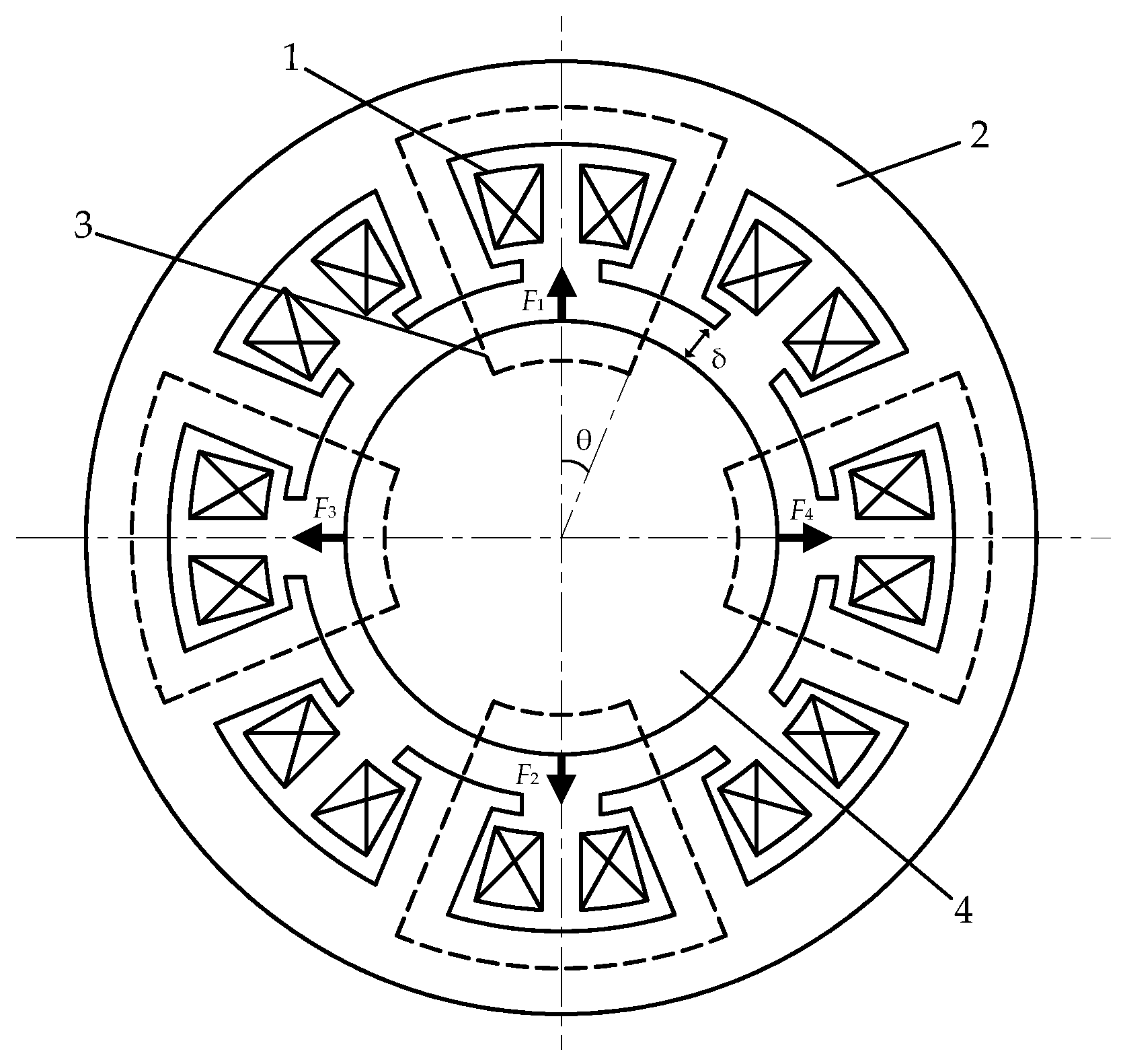
2. Model of the AMB
3. Sliding Mode Control for the AMB
3.1. Principle of Sliding Mode Control and Chattering Problem
3.2. Design and Stability Analysis of Second-Order Sliding Mode Controller
4. Modeling and Simulation of Control System
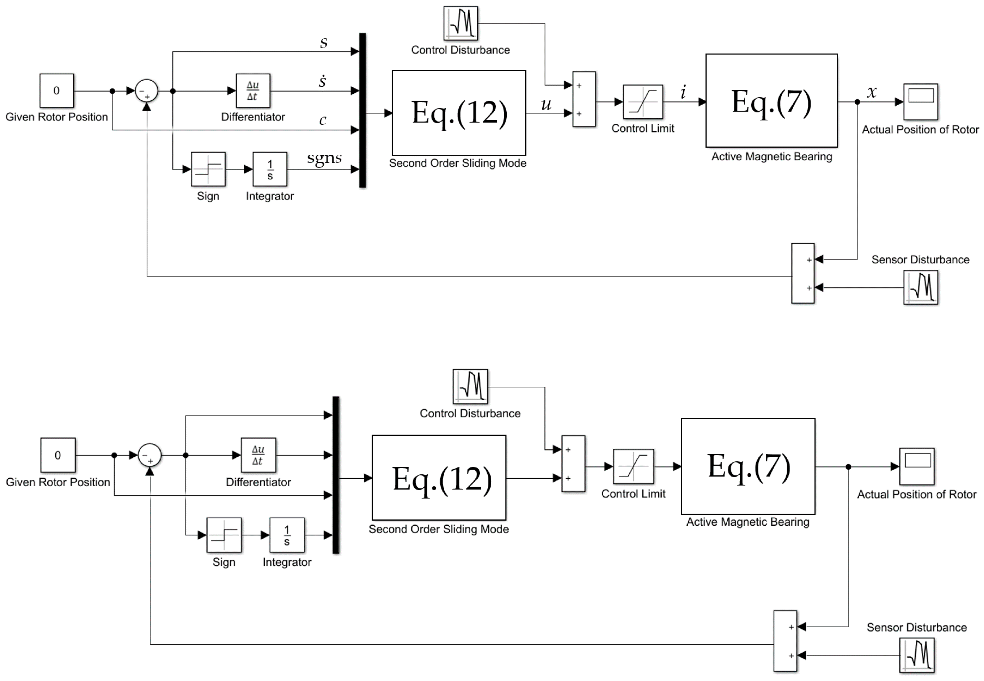
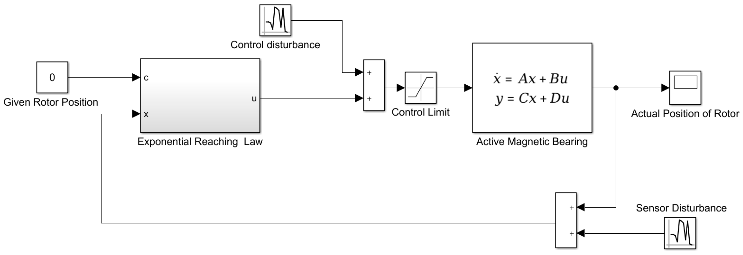
4.1. Establishment of Simulation Model
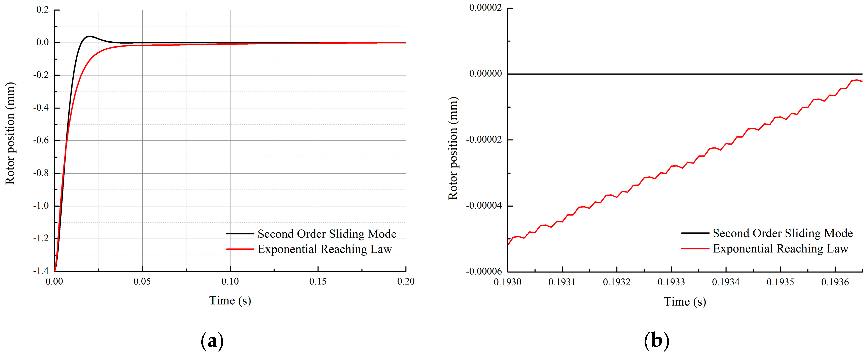
4.2. Comparison of Simulation Results
5. Experimental Verification
5.1. Establishment of Experimental Platform
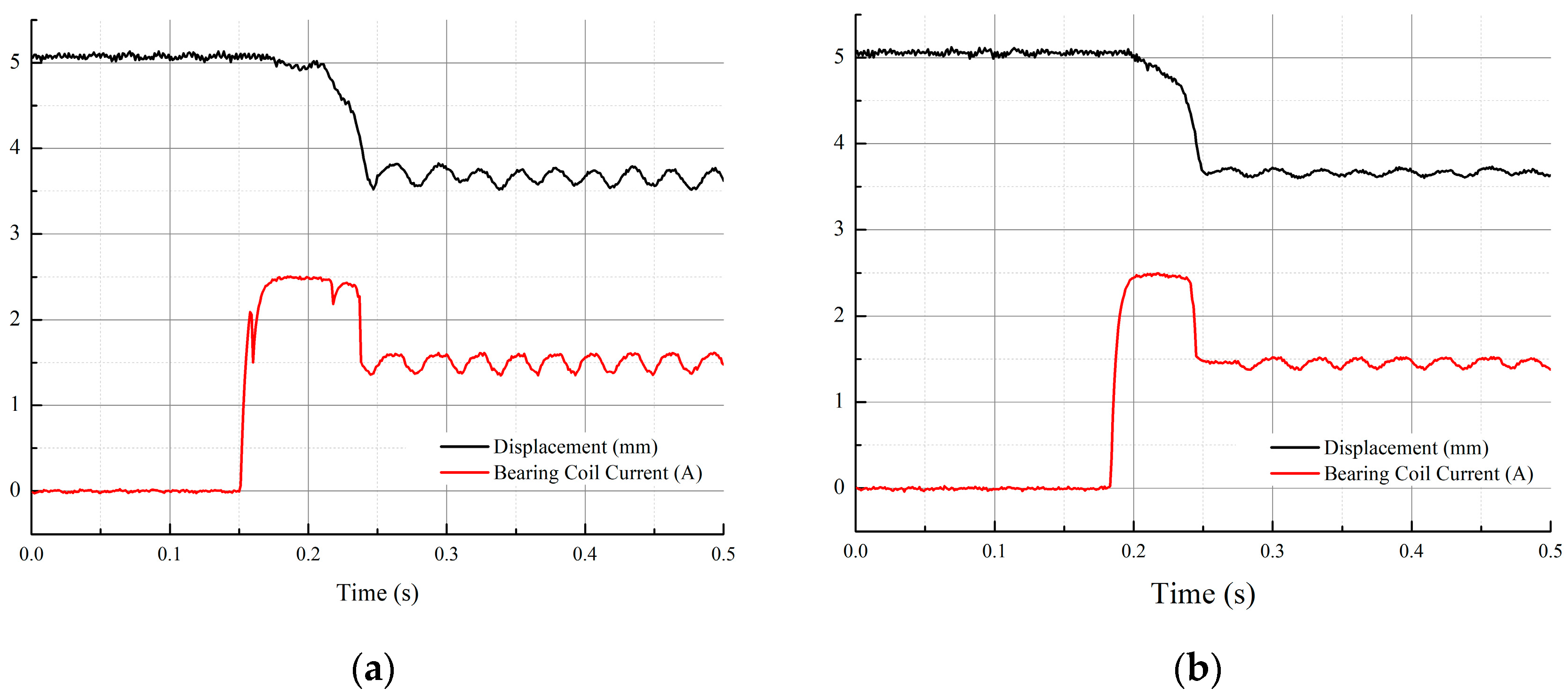
5.2. Starting Process
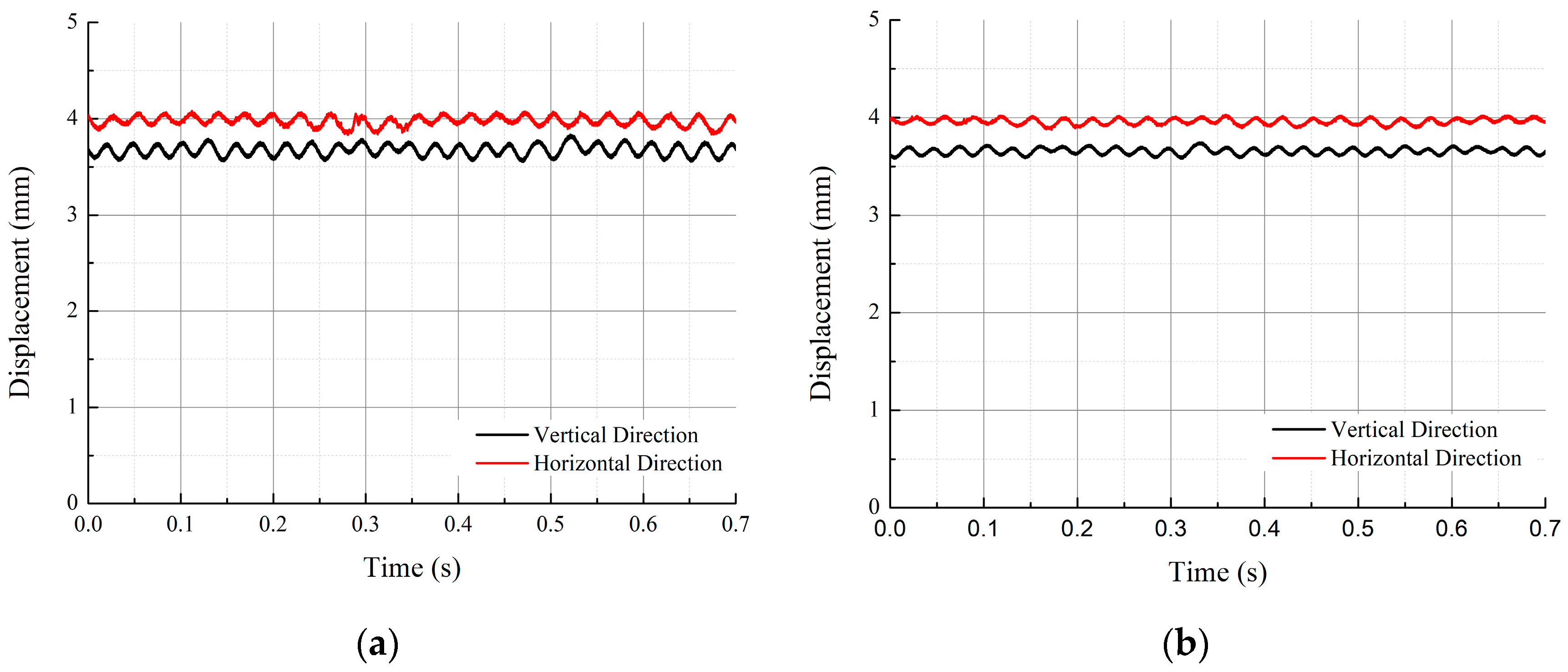
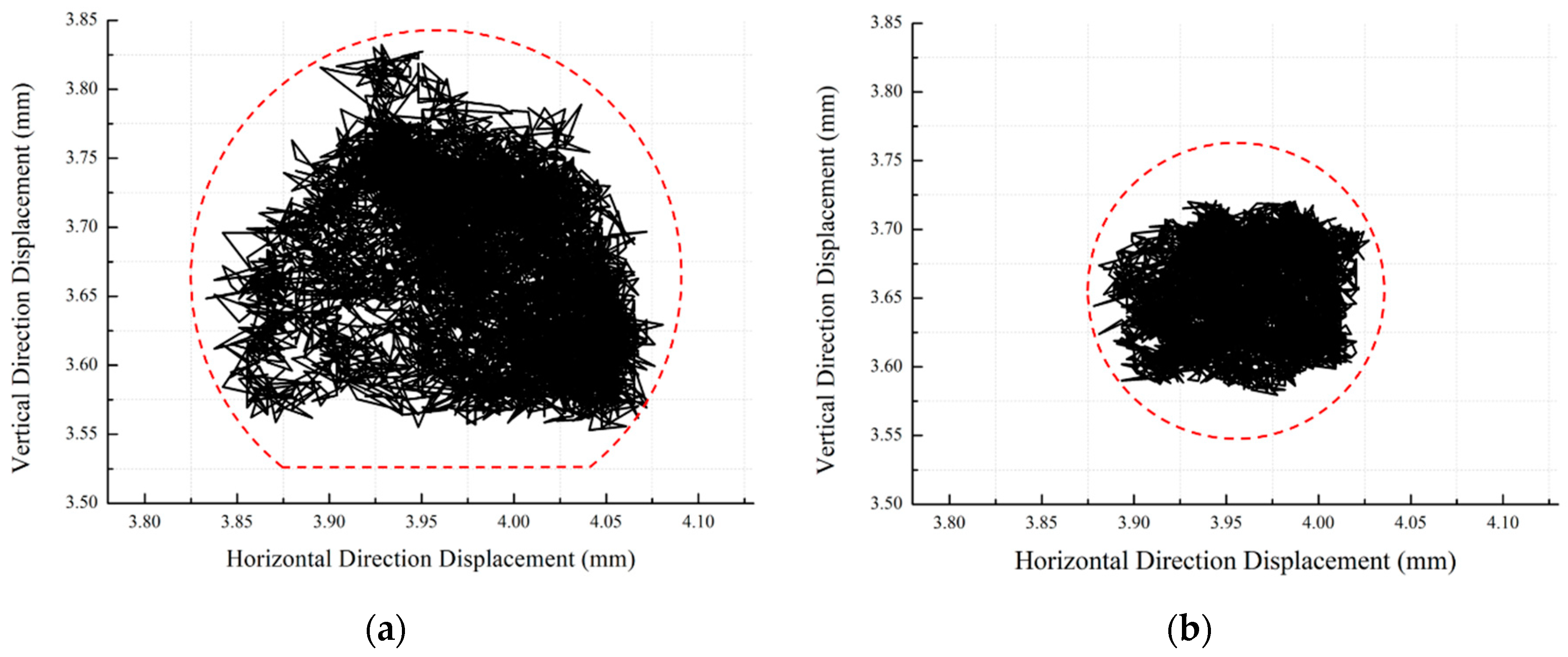
5.3. Stable Stage
6. Conclusions
- (1)
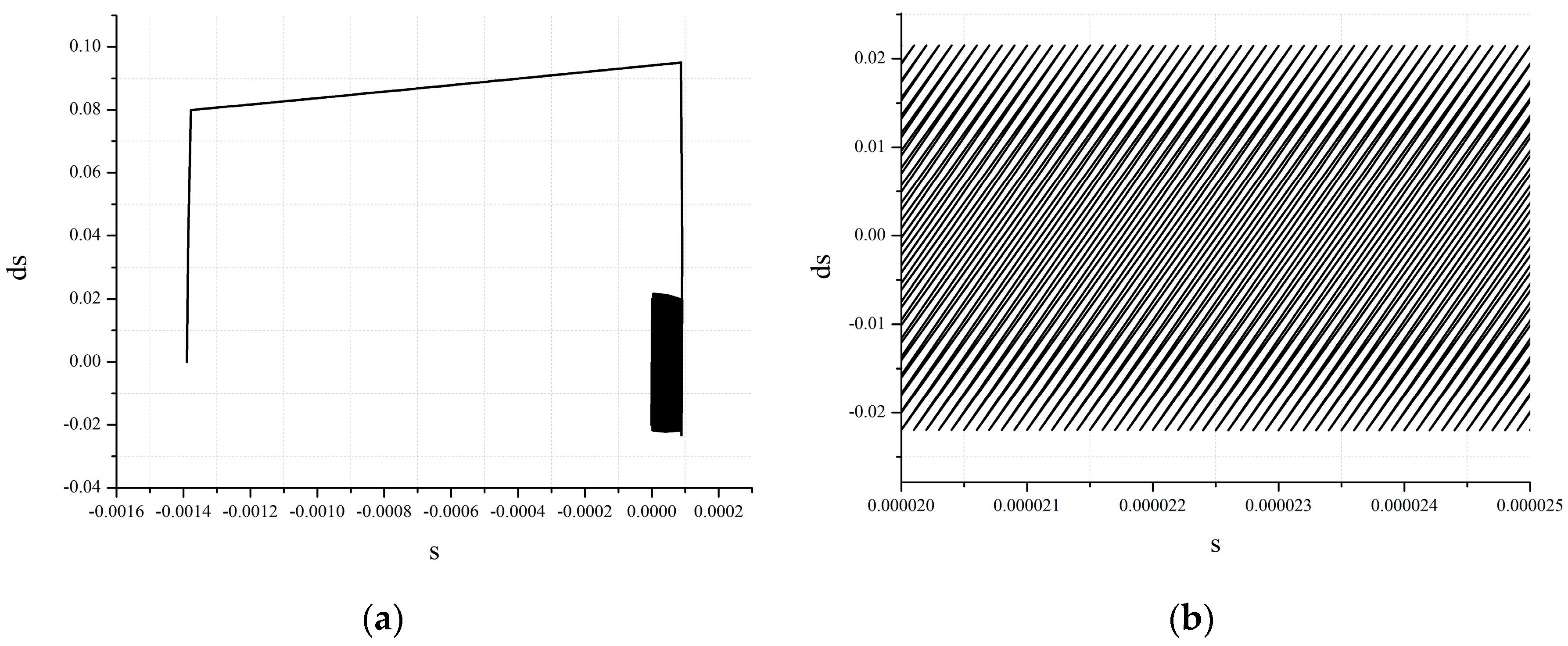
- The simulation results show that the second-order sliding mode controller has no high-frequency chattering phenomenon in the stable stage of AMB. Finally, the velocity of the sliding mode variable converges to zero, and its phase trajectory converges to zero in spiral form.
- (2)
- The experimental results show that the second-order sliding mode controller can achieve the stability control of AMB, and compared with the exponential reaching law for sliding mode controller, the stability time of the magnetic bearing is shortened by 50%, and the axis trajectory range is reduced by 41.5%.
Author Contributions
Funding
Conflicts of Interest
References
- Schweitzer, G.; Maslen, E.H. Magnetic Bearings: Theory, Design, and Application to Rotating Machinery; Springer: New York, NY, USA, 2009. [Google Scholar]
- Knospe, C.R. Active magnetic bearings for machining applications. Control Eng. Pract. 2007, 15, 307–313. [Google Scholar] [CrossRef]
- Vischer, D.; Bleuler, H. Self-sensing active magnetic levitation. IEEE Trans. Magn. 1993, 29, 1276–1281. [Google Scholar] [CrossRef]
- Noshadi, A.; Shi, J.; Lee, W.S.; Shi, P.; Kalam, A. System Identification and Robust Control of Multi-Input Multi-Output Active Magnetic Bearing Systems. IEEE Trans. Control. Syst. Technol. 2015, 24, 1227–1239. [Google Scholar] [CrossRef]
- Incremona, G.P.; Rubagotti, M.; Ferrara, A. Sliding Mode Control of Constrained Nonlinear Systems. IEEE Trans. Autom. Control. 2017, 62, 2965–2972. [Google Scholar] [CrossRef]
- Henzel, M.; Mazurek, P. The analysis of the control system of the active magnetic bearing. Electrodyn. Mechatron. Syst. 2011, 53–58. [Google Scholar] [CrossRef]
- Wajnert, D.; Zimon, J. Control system design for active magnetic bearing. In Proceedings of the 2009 2nd International Students Conference on Electrodynamic and Mechatronics, Opole, Poland, 19–21 May 2009; pp. 35–36. [Google Scholar]
- Su, T.-J.; Kuo, W.-P.; Giap, V.-N.; Vu, H.Q.; Nguyen, Q.-D. Active Magnetic Bearing System Using PID-surface Sliding Mode Control. In Proceedings of the 2016 Third International Conference on Computing Measurement Control and Sensor Network (CMCSN), Matsue, Japan, 20–22 May 2016. [Google Scholar]
- Zad, H.S.; Khan, T.I.; Lazoglu, I. Design and Adaptive Sliding-Mode Control of Hybrid Magnetic Bearings. IEEE Trans. Ind. Electron. 2017, 65, 2537–2547. [Google Scholar] [CrossRef]
- Cao, Z.; Dong, J.; Wani, F.; Polinder, H.; Bauer, P.; Peng, F.; Huang, Y. Sliding Mode Control with Neural Network for Active Magnetic Bearing System. In Proceedings of the IECON 2019-45th Annual Conference of the IEEE Industrial Electronics Society, Lisbon, Portugal, 14–17 October 2019; Institute of Electrical and Electronics Engineers (IEEE): Piscataway, NJ, USA, 2019. [Google Scholar]
- Geng, X.; Zhu, C. Sliding Mode Control Based on Linear Quadratic Regulator for an Active Magnetic Bearing Flexible Rotor Virtual Collocated System. In Proceedings of the 2019 22nd International Conference on Electrical Machines and Systems (ICEMS), Harbin, China, 11–14 August 2019; Institute of Electrical and Electronics Engineers (IEEE): Piscataway, NJ, USA, 2019. [Google Scholar]
- Levant, A.; Dvir, Y. Accelerated High-Order MIMO Sliding Mode control. In Proceedings of the 2014 13th International Workshop on Variable Structure Systems (VSS), Nantes, France, 29 June–2 July 2014; pp. 1–6. [Google Scholar] [CrossRef]
- Bartoszewicz, A.; Lesniewski, P. New Switching and Nonswitching Type Reaching Laws for SMC of Discrete Time Systems. IEEE Trans. Control. Syst. Technol. 2015, 24, 670–677. [Google Scholar] [CrossRef]
- Levant, A.; Shustin, B. Quasi-Continuous MIMO Sliding-Mode Control. IEEE Trans. Autom. Control. 2018, 63, 3068–3074. [Google Scholar] [CrossRef]
- Goyal, J.K.; Kamal, S.; Patel, R.B.; Yu, X.; Mishra, J.P.; Ghosh, S. Higher Order Sliding Mode Control-Based Finite-Time Constrained Stabilization. IEEE Trans. Circuits Syst. II Express Briefs 2020, 67, 295–299. [Google Scholar] [CrossRef]
- Zhang, X.; Su, H.; Lu, R. Second-Order Integral Sliding Mode Control for Uncertain Systems With Control Input Time Delay Based on Singular Perturbation Approach. IEEE Trans. Autom. Control. 2015, 60, 3095–3100. [Google Scholar] [CrossRef]
- Utkin, V. Discussion Aspects of High-Order Sliding Mode Control. IEEE Trans. Autom. Control. 2015, 61, 829–833. [Google Scholar] [CrossRef]
- Li, Z.; Zhou, S.; Xiao, Y.; Wang, L. Sensorless Vector Control of Permanent Magnet Synchronous Linear Motor Based on Self-Adaptive Super-Twisting Sliding Mode Controller. IEEE Access 2019, 7, 44998–45011. [Google Scholar] [CrossRef]
- Shah, I.; Rehman, F.U. Smooth Second Order Sliding Mode Control of a Class of Underactuated Mechanical Systems. IEEE Access 2018, 6, 7759–7771. [Google Scholar] [CrossRef]
- Kandil, M.S.; Micheau, P.; Trovão, J.P.; Bakay, L.S.; Dubois, M.R. Hybrid Magnetic Bearing Regulation via Super Twisting Control. In Proceedings of the 2015 15th International Conference on Control, Automation and Systems (ICCAS), Busan, Korea, 13–16 October 2015. [Google Scholar]


| Parameters | Designed Value |
|---|---|
| Coil turns | 150 |
| Number of poles | 8 |
| Stator out diameter | 120 mm |
| Rotor out diameter | 50 mm |
| Air gap length | 1.4 mm |
| Magnetic pole area | 129 mm2 |
| Magnetic pole angle | 22° |
| Parameters | Symbol | Value |
|---|---|---|
| Force-displacement coefficient | Kx | 4929.7 |
| Force-current coefficient | Ki | 6.9016 |
| Parameter1 | λ1 | 0.001 |
| Parameter2 | λ2 | 18 |
| Parameters | Symbol | Value |
|---|---|---|
| Constant reaching gain | ε | 0.3 |
| Exponential reaching gain | k | 100 |
| Controller | Stabilization Time | Trajectory Range |
|---|---|---|
| Exponential Reaching Law | 0.1 s | 0.397 mm |
| Second-Order Sliding Mode | 0.05 s | 0.232 mm |
Publisher’s Note: MDPI stays neutral with regard to jurisdictional claims in published maps and institutional affiliations. |
© 2020 by the authors. Licensee MDPI, Basel, Switzerland. This article is an open access article distributed under the terms and conditions of the Creative Commons Attribution (CC BY) license (http://creativecommons.org/licenses/by/4.0/).
Share and Cite
Wang, X.; Zhang, Y.; Gao, P. Design and Analysis of Second-Order Sliding Mode Controller for Active Magnetic Bearing. Energies 2020, 13, 5965. https://doi.org/10.3390/en13225965
Wang X, Zhang Y, Gao P. Design and Analysis of Second-Order Sliding Mode Controller for Active Magnetic Bearing. Energies. 2020; 13(22):5965. https://doi.org/10.3390/en13225965
Chicago/Turabian StyleWang, Xiaoyuan, Yaopeng Zhang, and Peng Gao. 2020. "Design and Analysis of Second-Order Sliding Mode Controller for Active Magnetic Bearing" Energies 13, no. 22: 5965. https://doi.org/10.3390/en13225965
APA StyleWang, X., Zhang, Y., & Gao, P. (2020). Design and Analysis of Second-Order Sliding Mode Controller for Active Magnetic Bearing. Energies, 13(22), 5965. https://doi.org/10.3390/en13225965