Abstract
In this research, automatic fouling cleaning systems that clean and prevent the deposit of fouling by regularly circulating sponge or ceramic balls are proposed. Characteristics of the finned and twisted inner tubes of the double pipe heat exchanger for the heat pump unit are also compared. Lastly, the 50RT-scale field test of the automatic fouling cleaning system integrated with the heat pump system was conducted by targeting temperature control of fish farms. The finned inner tube types presented a higher heat transfer rate than that of the twisted inner tube types. For the finned tube types, the refrigerant supply from the tangential direction was more advantageous due to the uniform distribution of refrigerant into 16 channels. The twisted tubes showed a higher water pressure drop than the finned inner tubes. An obvious increase in the fouling factor according to the operating hours was observed; however, it could be successfully decreased by operating the fouling cleaning system for 24 h. The overall heat transfer coefficient could be recovered from 5.87 kW/K to 24.05 kW/K, which is about 92% of the initial value. In short, the automatic fouling cleaning system can successfully prevent performance degradation of heat pump system due to fouling.
1. Introduction
Utilization of waste heat sources has been considered a solution to mitigate problems of greenhouse gases and improve energy efficiency, thereby reducing energy costs [1]. For instance, wastewater from public baths, which is around 300 K, shows a proper temperature level that can be used as a heat source for heat pump systems [2]. However, the utilization of wastewater inevitably brings about the deposition of undesired materials on the heat transfer surface [3], also known as fouling, which disturbs efficient heat transfer. It has been mentioned in the literature that the annual cost related to fouling in major industrialized countries is more than 4.4 billion U.S. dollars [4]. The cost related to the fouling of heat exchangers includes (1) production loss resulted from efficiency degradation; (2) loss of energy during planned or unplanned shutdowns because of fouling; and (3) maintenance cost of removing fouling or replacing the damaged equipment due to fouling [4].
Crystalline fouling is the most common kind of fouling formed due to the reverse solubility of salt in water. The solubility of the salts decreases as the temperature increases or pH changes [5], thereby causing deposits on the surface of a heat exchanger. The most representative fouling resulting from the use of water is known as calcium carbonate (CaCO3). The formation of fouling has been considered as a common problem when designing heat exchangers. The effect of fouling can be categorized into two types: (1) thermal insulation layer due to the low thermal conductivity of the fouling, which results in the decreased effectiveness of the heat exchanger; and (2) increase in pressure drop through the water tube because the formation of fouling reduces the cross-sectional area of the tube [6]. In terms of heat transfer disturbed by the barrier, this means that extra energy is needed to keep the desired operation output. The literature [7] reveals that the typical degradation of the performance of the heat transfer surface can be by as much as 80%, or sometimes complete failure.
Several research studies dealing with the effect of fouling on heat transfer are summarized as follows. Qureshi and Zubair investigated the performance degradation of a vapor compression system resulting from fouling and revealed an obvious decrease in cooling capacity with a decrease in overall heat transfer (UA) compared to clean conditions [8,9]. Hasan et al. compared the crystallization fouling on both a smooth and enhanced surface of a double-pipe heat exchanger at Reynolds numbers between 5000 and 20,000 [10]. They pointed out that surface enhancement on the outer surface of the inner tube is more effective than that on the inside surface of the inner tube to reduce fouling resistance, and the effect of the surface enhancement becomes more remarkable when the Reynolds number is relatively low. Esawy et al. studied the formation of fouling on finned tubes during the nucleate pool boiling of CaSO4 solutions according to fin density (19 and 26 fins/inch) and heat flux from 100 to 300 kW/m2 [11]. Bai et al. developed a fouling prediction model based on field and laboratory experiments to measure the fouling variation, and they proposed the recommended fouling resistance allowance for certain conditions [12].
Heat exchangers need to be properly cleaned to guarantee continuous and proper thermal performance, and the cleaning methods are categorized into online and offline techniques [13]. Due to the complexity of the process, it has been considered difficult to remove fouling with physical means. Thus, the use of chemical cleaning has been the most common option to remove fouling [14]. The chemical cleaning method has advantages of simplicity, being free of mechanical damage to the heat exchanger surface, requiring less labor than the physical method, and being able to reach areas that are inaccessible using the physical method. However, toxicity, possible chemical reaction of the cleanser with the metal surface, and disposal problems remain as disadvantages of the method [15]. The study of the antifouling effect of ultrasound on heat transfer according to the hardness of the deposit and temperature can also be found in the literature [16], as a part of the online technique [17]. Another online cleaning method involves the circulation of sponge rubber balls, which continuously circulate throughout the heat exchanger tubes with the water flow [18]. The cleaning system utilizing the balls, which are also known as projectiles, does not require the shut-down of the system to physically clean up the fouling, and it is entirely free from the safety problems associated with the usage of chemical cleansers. Several research studies have been conducted to prove the effect of this cleaning system [19,20,21,22]. However, research presenting the actual application of the fouling cleaning system integrated with a heat pump unit is still insufficient.
Therefore, this research introduces an actual case of applying an automatic fouling cleaning system integrated with a heat pump system, which targets the hot water supply to a fish farm. The automatic fouling cleaning system that this research proposes applies only one motor operated valve (MOV) owing to the application of the ejector, which is a lower number compared to traditional systems (3~4 MOV). The lower number of MOVs can be connected to simple flow control, with less possibility of a mechanical fault of the MOV. Experimental results showing the effectiveness of the automatic fouling cleaning system will be given based on the field test of the 50RT-scale heat pump unit targeting fish farms. This research also provides a comparison between two types of tubes as the inner pipe of the double pipe heat exchanger for the heat pump unit: inner tubes with a (1) finned or (2) twisted shape.
2. Heat Pump Applying Automatic Cleaning System
2.1. System Description
As mentioned earlier, the heat transfer and water flow through tubes are disturbed by fouling that is formed inside the heat exchanger. The heat pump system that this study proposes equips an automatic fouling cleaning system to mitigate performance degradation issues resulted from fouling. The remarkable aspect of this Heat-Pump-Applying Automatic Cleaning System is the periodic and regular circulation of the balls to prevent the deposit of fouling. That is to say, the balls automatically circulate the tube periodically with water flow, i.e., one time per hour for 20 s; thus, precipitation of foulant is prevented before being matured into the shape of fouling.
The automatic fouling cleaning system can be simply applicable to an already-existing heat pump unit by modifying the water pipe system. This study proposes two different automatic cleaning systems: one using sponge balls applicable to the inner tube with longitudinal fins, the other using ceramic balls applicable to the inner tube with a twisted shape. Figure 1 shows a schematic diagram of a heat pump system applying an automatic cleaning system. Here, “V1~5” refers to normal valves, “MOV1~3” denotes the motor operated valves, and “C.V” shows check valves. Figure 2 presents sponge and ceramic balls, also known as projectiles, used in the finned inner tubes and twisted inner tubes, respectively.
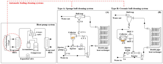
Figure 1.
Schematic diagram of a heat pump system applying automatic cleaning systems.
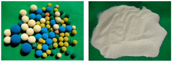
Figure 2.
Sponge and ceramic balls for the automatic fouling cleaning system.
The heat pump system in which the water source is exposed to various fouling, such as foulant from fish and small particles introduced from the sea, equips the automatic fouling cleaning system. Water flows through the inner tube, and refrigerant flows through the channel between the outer and inner tubes, which is the same as in the case of typical double-pipe heat exchangers. Either sponge balls or ceramic balls, shown in Figure 2, circulate through the inner tube, which is a water channel to prevent the precipitation of fouling. The evident difference between the tubes is the shape of the inner tube. Because it is hard for relatively large sponge balls to pass through the twisted inner tube while guaranteeing proper contact with the heat transfer surface, small ceramic balls (Db = 1 mm) are used as projectiles in this case. On the other hand, sponge balls (Db = 30.5 mm) circulate the finned inner tube while guaranteeing adequate contact with the heat transfer surface to remove or prevent fouling.
2.2. Working Principle of Automatic Fouling Cleaning Sstem
Three modes exist for the operation of the heat pump system applying the automatic fouling cleaning system: (1) cleaning process, (2) ball-recovery process, and (3) normal heat pump operation. Figure 3a,b shows the flow chart of the operation mechanism of the automatic fouling cleaning system applying a finned inner tube and a twisted inner tube, respectively. Here, “AFC” refers to the automatic fouling cleaning system, and “HP” means heat pumps.
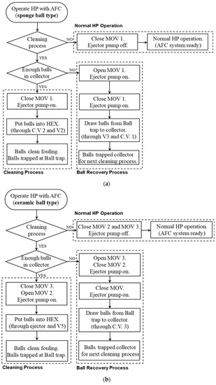
Figure 3.
(a) Flow chart of operation mechanism of automatic cleaning systems: finned type tube. (b) Flow chart of operation mechanism of automatic cleaning systems: twisted type tube.
Firstly, for the sponge ball type, the cleaning process begins when the heat exchanger cleaning is needed and when there are enough stacked balls in the ball collector. The inflow of balls occurs by the force of the pump (named “Ejector pump” in Figure 1). Because MOV 1 is closed in this process, the ejector just takes the role of connector, rather than making a suction flow toward it. The balls are thus carried to the main stream of water flow by the ejector pump, and then circulate in the heat exchanger and mixed into the main water flow. At the outlet side of the heat exchanger, the installed ball trap filters out the balls from the water flow due to the strainer that is narrow enough to capture the balls but not too fine to disturb the water flow. Next, the ejector generates suction force to draw the trapped balls in the ball trap into the collector. This process occurs by simply opening MOV 1. Because the strainer is installed at the bottom of the ball collector, the sponge balls do not flow into the ejector or the main stream during this process. Both the cleaning process and the ball-recovery process normally continue for 30 s, and approximately 60 cycles are repeated per day. However, it should be noted that the time for the cleaning and recovery processes may be flexible considering the degree of contamination of heat exchangers. This is because this automatic fouling cleaning system works together with the operation of the heat pump system without pausing the heat pump system for cleaning. Furthermore, the mass flow rate passing through the ejector pump is merely 1~2% that of the main stream, which provides flexibility in deciding the cleaning and recovery time. The ejector pump is turned off and MOV 1 is closed for normal heat pump operation after finishing the ball-recovery process, which is the state ready for the next cleaning process.
The ceramic ball type is also operated with a somewhat different principle from that of the sponge ball type. While the cleaning process and the ball-recovery process are entirely separated in the sponge ball type, these processes in the ceramic ball type occur simultaneously. As MOV 2 is opened, ceramic balls (Db = 1 mm) are drawn into the suction part of the ejector by the function of the ejector and the ejector pump from the collector. It should be noted that this is possible because the suction port connected to MOV 2 is located at the bottom part of the collector, where the heavy ceramic balls are stacked. These balls are discharged and then circulate in the twisted inner tube of the double pipe heat exchanger as they clean the fouling on the surface. Then, the ceramic balls are trapped in the ball trap by a cyclone effect as the balls sink to the bottom of the ball trap due to their heavy specific weight (4.0 g/cm3). At this moment, the balls are attracted to the collector due to the suction force from the ejector. Therefore, the ceramic balls repeat supply and recovery continuously as long as the ejector pump works, and MOV 2 is opened. After the cleaning process occurs for approximately 10 min, MOV 2 is closed to cease the supply of the balls. Then, MOV 3 is opened to continue the recovery of the ceramic balls by continuing suction water flow through the upper side of the collector, where the suction force cannot overcome the gravity force of the ceramic balls. As a result, ceramic balls are collected in the collector for the next cleaning process. The ejector pump is turned off, and MOV 2 and 3 are closed for the normal heat pump operation after finishing the ball-recovery process, which is the state ready for the next cleaning process.
3. Comparison of Finned/Twisted Tubes
3.1. Geometric Shape of Finned/Twisted Tubes
In this study, the heat transfer performance of two different types of double pipe heat exchangers was compared: (1) a finned inner tube and (2) a twisted inner tube for the double pipe heat exchangers. Each tube has distinct characteristics in its geometric shape, as shown in Figure 4.
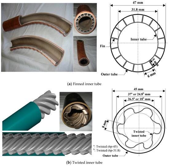
Figure 4.
Two types of double pipe heat exchangers for the automatic cleaning system.
Firstly, the finned inner tube applies 16 fins through the axial direction to effectively increase the heat transfer area. The fin pitch is 6 mm, the height of the fins is 5 mm, and the fin thickness is 1.2 mm. The diameter of the outer tube made of copper is 47 mm, and that of the inner tube made of titanium is 31.8 mm. The process of making the double pipe heat exchanger involving a finned inner tube is as follows. A plain titanium tube is inserted into an internally finned aluminum tube. Before inserting the tube, all of the dust and undesired particles between fins are removed properly. These combined tubes are inserted again into a copper tube to protect the physically weak aluminum tube. Then, the set of tubes undergoes a tube drawing process in which the pipe shrinks to the designed diameter so that the internally finned structure can be perfectly attached to the outer surface of the titanium tube. Finally, the set of integrated tubes undergoes a bending process, which rolls the tubes into four layers for the compact structure.
By comparison, the process of making the double-pipe heat exchanger involving a twisted inner tube is relatively simple. The commercial twisted tube made of titanium is inserted into the steel outer tube, and then the set of tubes undergoes the same bending process as the finned type. As shown in the drawing of Figure 4b, the inner and outer diameters of the titanium tube are 26.5 and 37 mm, respectively, for Twisted (6p-45). For Twisted (6p-31.8), the inner and outer diameters of the titanium tube are 18 mm and 24.8 mm, respectively. The titanium tube has six twisted points. Ten twists exist in each 10 cm of the tube, and the distance between the twisted shape is 9 mm. Table 1 summarizes the specification of tubes for the double pipe heat exchangers.

Table 1.
Specifications of tubes for double pipe heat exchangers.
3.2. Performance Comparison of HEX (Heat Exchanger) Using Finned/Twisted Tubes
Figure 5 presents an experimental system for a performance test of double pipe heat exchangers for the automatic fouling cleaning system. The cooling and heating performance of double-pipe heat exchangers using a finned and a twisted inner tube was analyzed experimentally. Installed constant temperature baths supplied a heat source and cooling water with constant temperature, and pressure and temperature sensors and flow meters were installed to measure the experimental values for the analysis. Specifications and uncertainty of measuring devices are summarized in Table 2. The combined uncertainty of the heat transfer rate is calculated using the uncertainty of water flow rate and water inlet and outlet temperature as revealed in Equation (1) [23].
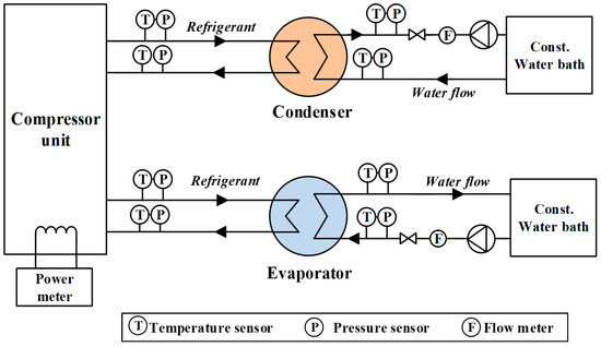
Figure 5.
Experimental system for performance test of double pipe heat exchangers.
Table 2.
List of measuring devices, specifications, and uncertainty.
To analyze the heat transfer rate, the water temperatures at the evaporator and condenser side were considered to be same to reflect operating conditions of actual application in fish farms. The water temperature was varied from 12 to 27 °C to include temperature variation of surface seawater during the winter and summer seasons. Here, the water flow rates of both evaporator and condenser side were held constant at 3000 kg/h. The evaporation and condensation pressure were 4.8~7.2 bar and 12.1~16 bar, respectively. The water flow rate was controlled from 13,000 to 43,000 kg/h to analyze the water side pressure drop. Under this condition, the Reynolds number ranged from 10,578 to 49,946. All of the measurements were recorded every 2 s.
Double-pipe heat exchangers using the finned and twisted inner tubes were tested. Each type involves two different geometries. Firstly, the finned inner tube type includes (Cu-Al-Ti)ver and (Cu-Al-Ti)tan. The difference between these two types is the location of the refrigerant inlet port as described in Figure 6. In the type “ver”, the refrigerant inlet port is placed in the vertical direction from the center of the pipe. The terms “Cu”, “Al”, and “Ti” represent copper, aluminum, and titanium, respectively. In the type “tan”, the refrigerant inlet port is placed in the tangential direction of the pipe. The end-fitting is installed at the edge of the double-pipe heat exchanger to separate the refrigerant and water channels. The inner water pipe, which is a titanium tube, extends beyond the refrigerant channel so that the end-fitting can seal and separate the refrigerant channel from the atmosphere or water channel. Either liquid- or vapor-stage refrigerant flows into the refrigerant channel of the heat exchanger through the refrigerant inlet port. Because the refrigerant channel of the heat exchanger is divided into 16 pieces, uniform distribution of refrigerant flow is required. Study of the distribution of the refrigerant flow in double pipe heat exchangers can be found in the research of Lee et al. [24], using commercial software ANSYS CFX. They conducted CFD (computational fluid dynamic) analysis to examine the uniformity of the refrigerant flow according to the position of the inlet port, the length of the zone in which the refrigerant rotates, and the flow rate of the refrigerant. Secondly, the twisted inner tube type also includes 6p-31.8 and 6p-45. The difference between these two types is the diameter of the inner titanium tube. The numbers 31.8 and 45 denote the diameter of the tube before the twisting process, and 6p refers to the number of twisted points.
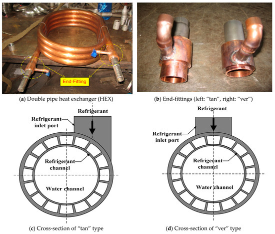
Figure 6.
Two types of end-fittings of the double pipe heat exchanger.
Figure 7 shows a comparison of the heat transfer rate between finned and twisted inner tube types according to the supplied water temperature. The water flow rate is controlled to be 3000 kg/h in all cases. In both cooling and heating experiments, the heat transfer rate tended to increase as water-supply temperature increased. The finned inner tube types presented a higher heat transfer rate than those of twisted inner tube types. This is due to the larger heat transfer area of the fins. The finned type (Cu-Al-Ti)tan showed a higher performance than (Cu-Al-Ti)ver. The reason for this difference is due to the uniformity of the distribution of the refrigerant to 16 channels. From the result, it can be estimated that the (Cu-Al-Ti)tan type has a more uniform refrigerant distribution than that of (Cu-Al-Ti)ver, which corresponds to the CFD result of Lee et al. [24]. In terms of the comparison of the two types of twisted tubes, 6p-45 presented a higher heat transfer rate than 6p-31.8. Because the twisted shape is the same for these two types, the heat transfer area depends on the diameter of the tubes. That is, the type with the larger diameter has the larger heat transfer area. Meanwhile, it is clear that the water flows with the higher velocity for type 6p-31.8 than for 6p-45, because the water flow rate is controlled to be the same for all types (3000 kg/h). Therefore, the larger heat transfer area affects the heat transfer rate more than the effect of the enhanced heat transfer coefficient.
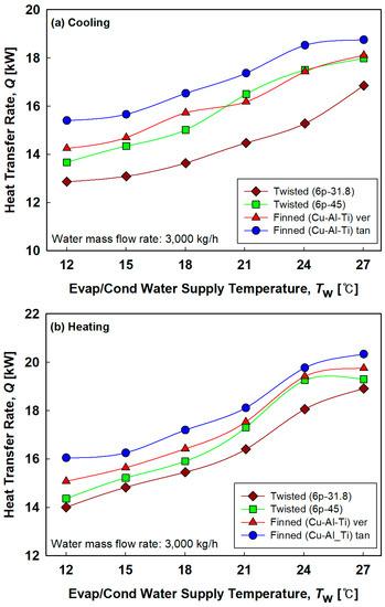
Figure 7.
(a) Comparison of heat transfer rate between finned and twisted types according to the supplied water temperature: cooling mode. (b) Comparison of heat transfer rate between finned and twisted types according to the supplied water temperature: heating mode.
Figure 8 depicts water-side pressure drops of various tube types according to the water flow rate. The pressure drop should be considered carefully when deciding the specific model of water pumps for actual system application. In general, the twisted tubes showed a higher pressure drop than finned inner tubes due to their geometric shape. The highest pressure drop was found for the twisted tube 6p-31.8 due to the higher water velocity and the tube’s geometric shape. However, there was no difference in pressure drop between the two finned inner tube types (Cu-Al-Ti)tan and (Cu-Al-Ti)ver because they do not differ in geometric structure for water flow.
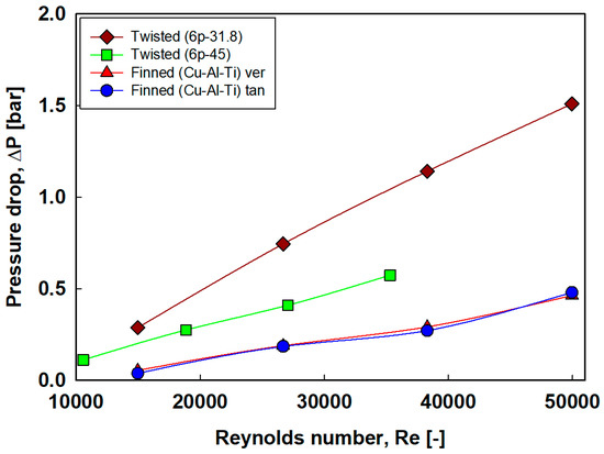
Figure 8.
Water side pressure drops of various tubes according to Reynolds number.
Based on the higher heat transfer rate and the lower water side pressure drop, the finned inner tube type (Cu-Al-Ti)tan was selected as the design for the double-pipe heat exchanger for the field test of the 50RT-scale heat pump unit targeting fish farms.
Furthermore, in terms of the cleaning system, the type applying small (diameter: 1 mm) and heavy (density: 4.0 g/cm3) ceramic balls instead of sponge balls has faced problems with the recovery of the balls [25]. That is, some of the ceramic balls remain inside of the double pipe heat exchanger or somewhere in the system. In contrast, the type applying sponge balls is free from the problem of ball recovery [26]. This is because the sponge balls are lighter and much larger than the ceramic balls, and only a few balls circulate.
4. 50 RT-Scale Field Test Targeting Fish Farms
4.1. General Description of Field Test
In aquaculture, heating of the water is required to provide an environment for better growth rate or spawning of species [27]. Because different species have different optimal temperatures for growth, precise and constant water temperature control is often connected to economic benefits in aquaculture. In the case of the Republic of Korea, heated water for most fish farms’ pools is supplied from oil boilers, and ice or dry ice is poured into the pool if chilled water is needed. It has been proven in numerous studies that the application of heat pump systems can dramatically save operating costs compared to oil boiler systems due to the high efficiency of the former [28,29,30,31]. An economic benefit can also be expected in the case of aquaculture; however, the concerns relating to fouling issues may be somewhat more serious because the heat pump systems of such fish farms are normally exposed to various foulants from species and small particles introduced from the sea. For this reason, the application of the automatic fouling cleaning system should be more emphasized.
Figure 9 shows a schematic diagram of the actual application of a heat pump system with the automatic cleaning system for a fish farm, and Table 3 provides detailed specifications of the unit. The target fish farm mainly raises small fries of flatfish, rockfish, and rock bream. PVC pipes are selected for water due to their outstanding corrosion resistance. Generally, the diameter of water pipes (100 A) is set for the water velocity to be about 1.0 m/s when the water mass flow rate is 30,000 kg/h, for acceptable pressure drop. The installed water pumps can supply 40,000 kg/h of seawater when the pump head is 2 m, and their impellers are made from STS316 with proper corrosion resistance.
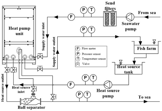
Figure 9.
Schematic diagram of the 50 RT-scale field test for a fish farm.
Table 3.
Specifications of a 50 RT-scale field test unit.
The installed heat pump system operated without the function of an automatic fouling cleaning system for 60 days to analyze performance degradation due to fouling. Then, the automatic fouling cleaning system worked for 24 h to remove fouling. Figure 10 presents the installation process of 50 RT-scale heat pumps in the field on a fish farm.
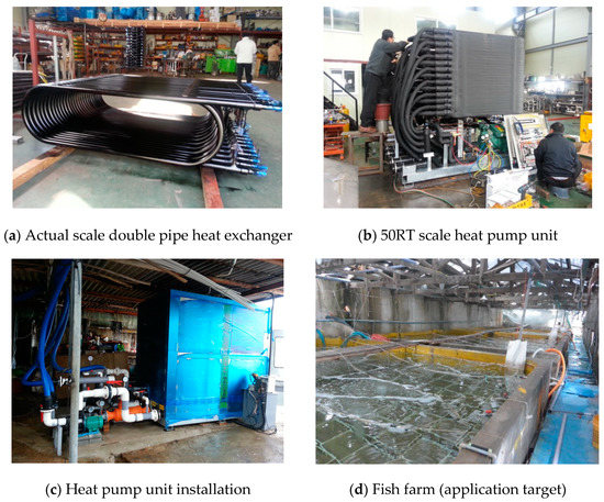
Figure 10.
Installation of 50RT scale heat pump on a fish farm for field tests.
4.2. Results of Filed Test at Fouling Condition
Figure 11 represents the variation of the fouling factor (Rf) according to heat pump operating hours. Equation (2) was used to calculate the fouling factor. Here, Do and Di show the diameter of the tube, and UA denotes the overall heat transfer coefficient. ho and hi represent the convective heat transfer coefficient of inner and outer side, respectively. denotes the fin efficiency, means thermal conductivity of tube, L is the tube length [32].
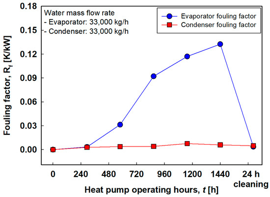
Figure 11.
Variation of fouling factor according to heat pump operating hours.
The overall heat transfer coefficient (UA) was calculated based on experimentally measured water mass flow rate, water inlet and outlet temperature, and the refrigerant saturation temperature as shown in Equations (3)–(6). Here, TREF refers to the refrigerant temperature. Tw,i and Tw,o are water inlet and outlet temperature, respectively. mw the is water mass flow rate, represents the logarithmic mean temperature difference [33].
It was assumed that the fouling factor at the initial operation was zero. That is, the experimentally obtained overall heat transfer resistance at the initial operation represents the total resistance including all terms in Equation (2), which may be considered almost constant for simplicity. In other words, the fouling factor can be simply calculated by subtracting the initial total thermal resistance (Rt) value from the future Rt value.
The obvious increase in fouling factor according to the operating hours was observed for the case of the evaporator. On the other hand, the increment in the condenser was not as severe as that in the evaporator. The difference can be explained as follows. Fresh seawater should be supplemented continuously to the fish farm to guarantee a suitable environment for the fishes to grow up. At the same time, the same amount of contaminated water should drain from the fish farm to the heat source tank. That is, the wastewater in the heat source tank can be utilized as the heat source of the heat pump system. This contaminated heat source water flows into the evaporator during the heating operation of the heat pump, and fresh seawater is supplied to the condenser, which is why the fouling factor of the evaporator increased dramatically according to the heat pump operating hours. The fouling factor successfully decreased as the fouling cleaning system operated for 24 h, to a value similar to the initial level.
Figure 12 depicts the variation of the overall heat transfer coefficient according to the heat pump operating hours. The value of the evaporator after operation for 60 days was about 5.87 kW/K, which is less than 1/4 of the initial value (26.38 kW/K). The overall heat transfer coefficient could be recovered by operating the cleaning system for 24 h, up to 24.05 kW/K, which is about 92% of the initial value.
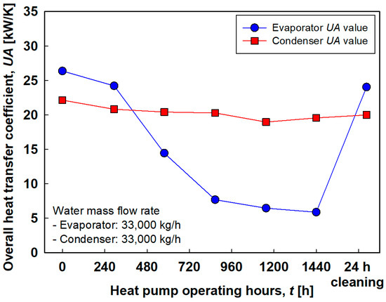
Figure 12.
Variation of overall heat transfer coefficient according to heat pump operating hours.
Figure 13 represents the variation of heat pump capacity and compressor power consumption according to heat pump operating hours. The experimentally measured evaporation capacity, condensation capacity, and compressor power at the initial conditions of about 182, 223, and 39.2 kW, respectively. After operation for 60 days, the evaporation capacity, condensation capacity, and compressor power were 106 kW (58% of the initial), 137 kW (62% of the initial), and 30.4 kW (78% of the initial), respectively. Operation of the cleaning system for 24 h enabled the evaporation capacity and the condensation capacity to be recovered by 93% and 83% of the initial value, respectively. However, it should be noted that the heat source temperature of the season when operating the cleaning system (22 October) was lower than the initial heat source temperature (22 August). Therefore, higher performance recovery is expected if it is assumed to be compared with the fair condition.
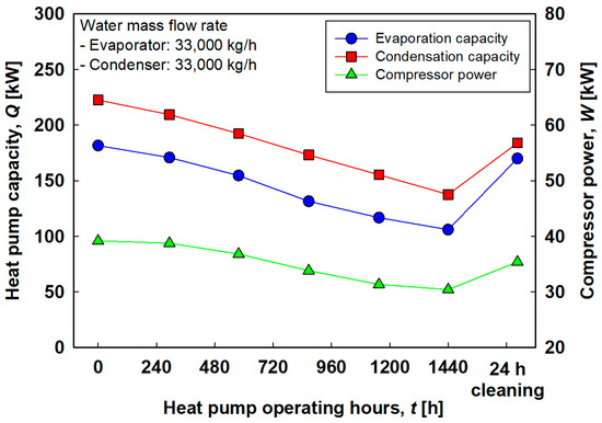
Figure 13.
Variation of heat pump capacity and compressor power consumption according to heat pump operating hours.
Figure 14 shows the variation of the coefficient of performance (COP) according to heat pump operating hours. It can be seen that COP also increases as the heat transfer rate is recovered by the operating cleaning system. The detailed values of heat transfer rate, compressor power, and COP according to the operating hours are summarized in Table 4.
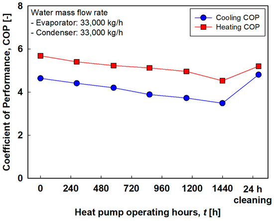
Figure 14.
Variation of COP according to heat pump operating hours.
Table 4.
Summary of heat transfer rate, compressor power, and COP according to operating hours.
5. Conclusions
In this research, automatic fouling cleaning systems that clean and prevent the deposit of fouling by the regular use of circulating sponge or ceramic balls are proposed. Moreover, characteristics of the finned and twisted inner tubes of the double pipe heat exchanger for the heat pump unit are compared. Lastly, the 50RT-scale field test of the automatic fouling cleaning system integrated with the heat pump system was conducted by targeting temperature control of fish farms.
There were three modes for the operation of the heat pump system applying the automatic fouling cleaning system: (1) cleaning process; (2) ball-recovery process; and (3) normal heat pump operation. The modes were changed by controlling valves and the ejector pumps. The aim of this system was to prevent the formation of fouling through regular and periodic circulation of balls. In addition, the automatic fouling cleaning system can be applied to an already existing heat pump unit by modifying the water pipe system.
The finned inner tube types presented a higher heat transfer rate than those of the twisted inner tube type because of the larger heat transfer area of the fins. For the finned types, the uniformity of distribution of refrigerant flow was affected by the position of the refrigerant inlet port. The experimental results showed that the supply from the tangential direction of the pipe was more advantageous in terms of thermal performance of the heat pump. Generally, the twisted tubes showed a higher pressure drop than finned inner tubes because of the geometric shape of the tube. Thus, based on the higher heat transfer rate and the lower water-side pressure drop, the finned inner tube type (Cu-Al-Ti)tan was selected as the design for the double-pipe heat exchanger for the field test of the 50RT-scale heat pump unit targeting fish farms.
Because fish farms are normally exposed to various foulants, the application of the automatic fouling cleaning system should be emphasized. The obvious increase in fouling factor according to the operating hours was observed; however, it was successfully reduced when the fouling cleaning system operated for 24 h, and the value returned to close to the initial level. Thus, the overall heat transfer coefficient could be recovered from 5.87 to 24.05 kW/K, which is about 92% of the initial value. In addition, the evaporation capacity and the condensation capacity were recovered by 93% and 83% of the initial value, respectively.
Therefore, it can be said that the application of an automatic fouling cleaning system can successfully prevent performance degradation of the heat pump system due to fouling.
Author Contributions
Conceptualization, S.-H.S. and O.K.K.; Experiments, S.-H.S. and O.K.K.; Investigation, A.A.S.; Writing original draft, S.-H.S. and A.A.S.; Writing-review and editing, A.A.S.; Supervision, O.K.K.; All authors have read and agreed to the published version of the manuscript.
Funding
This research received no external funding.
Conflicts of Interest
The authors declare no conflict of interest.
References
- Rakib, M.I.; Saidur, R.; Mohamad, E.N.; Afifi, A.M. Waste-heat utilization—The sustainable technologies to minimize energy consumption in Bangladesh textile sector. J. Clean. Prod. 2017, 142, 1867–1876. [Google Scholar] [CrossRef]
- Baek, N.C.; Shin, U.C.; Yoon, J.H. A study on the design and analysis of a heat pump heating system using wastewater as a heat source. Sol. Energy 2005, 78, 427–440. [Google Scholar] [CrossRef]
- Oon, C.S.; Kazi, S.N.; Hakimin, M.A.; Abdelrazek, A.H.; Mallah, A.R.; Low, F.W.; Tiong, S.K.; Badruddin, I.A.; Kamanger, S. Heat transfer and fouling deposition investigation on the titanium coated heat exchanger surface. Powder Technol. 2020, 373, 671–680. [Google Scholar] [CrossRef]
- Ogbonnaya, S.K.; Ajayi, O.O. Fouling phenomenon and its effect on heat exchanger: A review. Front. Heat Mass Transf. 2017, 9, 2007–2018. [Google Scholar] [CrossRef]
- Andritsos, N.; Karabelas, A.J. Calcium carbonate scaling in a plate heat exchanger in the presence of particles. Int. J. Heat Mass Transf. 2003, 46, 4613–4627. [Google Scholar] [CrossRef]
- Awad, M. Fouling of Heat Transfer Surfaces; InTech Open Access Publisher: Rijeka, Croatia, 2011; ISBN 978-953-307-226-5. [Google Scholar]
- Jamialahmadi, M.; Müller-Steinhagen, H. A new model for the effect of calcium sulfate scale formation on pool boiling heat transfer. J. Heat Transf. 2004, 126, 507–517. [Google Scholar] [CrossRef]
- Qureshi, B.A.; Zubair, S.M. Performance degradation of a vapor compression refrigeration system under fouled conditions. Int. J. Refrig. 2011, 34, 1016–1027. [Google Scholar] [CrossRef]
- Qureshi, B.A.; Zubair, S.M. The impact of fouling on performance of a vapor compression refrigeration system with integrated mechanical sub-cooling system. Appl. Energy 2012, 92, 750–762. [Google Scholar] [CrossRef]
- Hasan, B.O.; Jwair, E.A.; Craig, R.A. The effect of heat transfer enhancement on the crystallization fouling in a double pipe heat exchanger. Exp. Therm. Fluid Sci. 2017, 86, 272–280. [Google Scholar] [CrossRef]
- Esawy, M.; Malayeri, M.R.; Müller-Steinhagen, H. Crystallization fouling of finned tubes during pool boiling: Effect of fin density. Heat Mass Transf. Stoffuebertragung 2010, 46, 1167–1176. [Google Scholar] [CrossRef]
- Bai, X.; Luo, T.; Cheng, K.; Chai, F. Experimental study on fouling in the heat exchangers of surface water heat pumps. Appl. Therm. Eng. 2014, 70, 892–895. [Google Scholar] [CrossRef]
- Lestina, T. Heat Exchangers Fouling, Cleaning and Maintenance BT—Handbook of Thermal Science and Engineering; Kulacki, F.A., Ed.; Springer International Publishing: Cham, The Netherland, 2017; pp. 1–33. ISBN 978-3-319-32003-8. [Google Scholar]
- Jamialahmadi, M.; Müller-Steinhagen, H. Heat exchanger fouling and cleaning in the dihydrate process for the production of phosphoric acid. Chem. Eng. Res. Des. 2007, 85, 245–255. [Google Scholar] [CrossRef]
- Müller-Steinhagen, H.; Malayeri, M.R.; Watkinson, A.P. Heat exchanger fouling: Mitigation and cleaning strategies. Heat Transf. Eng. 2011, 32, 189–196. [Google Scholar] [CrossRef]
- Chen, Y.; Sun, S.; Lai, Y.; Ma, C. Influence of ultrasound to convectional heat transfer with fouling of cooling water. Appl. Therm. Eng. 2016, 100, 340–347. [Google Scholar] [CrossRef]
- Fontdevila, A.L. Fouling of a Double Pipe Heat Exchanger. Ph.D. Thesis, Dublin City University, Dublin, Ireland, 2004. [Google Scholar]
- Awais, M.; Bhuiyan, A.A. Recent advancements in impedance of fouling resistance and particulate depositions in heat exchangers. Int. J. Heat Mass Transf. 2019, 141, 580–603. [Google Scholar] [CrossRef]
- Jalalirad, M.R.; Abd-Elhady, M.S.; Malayeri, M.R. Cleaning action of spherical projectiles in tubular heat exchangers. Int. J. Heat Mass Transf. 2013, 57, 491–499. [Google Scholar] [CrossRef]
- Abd-Elhady, M.S.; Malayeri, M.R.; Jalalirad, M.R. Intensification of the cleaning action of structurally different projectiles by multiple injections and changing injection rate. Desalination 2014, 337, 52–59. [Google Scholar] [CrossRef]
- Jalalirad, M.R.; Malayeri, M.R. A Criterion for the Selection of Projectiles for Cleaning Tubular Heat Exchangers. In Proceedings of the International Conference on Heat Exchanger Fouling and Cleaning, Budapest, Hungary, 9–14 June 2013; Volume 2013, pp. 332–338. [Google Scholar]
- Abd-Elhady, M.S.; Malayeri, M.R. Impact of hardness and surface texture on cleaning action of various projectiles. Chem. Eng. Res. Des. 2015, 94, 153–163. [Google Scholar] [CrossRef]
- Seol, S.H.; Nagano, K.; Togawa, J. Modeling of adsorption heat pump system based on experimental estimation of heat and mass transfer coefficients. Appl. Therm. Eng. 2020, 171, 115089. [Google Scholar] [CrossRef]
- Lee, S.-H.; Cha, D.-A.; Kwon, O.-K. Flow Characteristic with Distance of Inlet Port and Rotating Length of Fluid in the Double Heat Exchanger. J. Korea Soc. Power Syst. Eng. 2013, 17, 51–57. [Google Scholar] [CrossRef][Green Version]
- Chae, H.-M.; Kwon, J.-T.; Cha, D.-A.; Kwon, O.-K. The Measurements of Ball Recovery Rate for the Cleaning Apparatus in Plate Heat Exchanger Using Ceramic Ball. J. Korea Soc. Power Syst. Eng. 2014, 18, 38–44. [Google Scholar] [CrossRef][Green Version]
- Kwon, O.-K.; Seol, W.-S. Research and Development of Sea Water Heat Pump. J. Korea Soc. Power Syst. Eng. 2013, 17, 7–13. [Google Scholar] [CrossRef]
- Aquaculture Engineering; Lekang, O.-I., Ed.; John Wiley & Sons: Hoboken, NJ, USA, 2013; ISBN 9781118496077. [Google Scholar]
- Bergamini, R.; Jensen, J.K.; Elmegaard, B. Thermodynamic competitiveness of high temperature vapor compression heat pumps for boiler substitution. Energy 2019, 182, 110–121. [Google Scholar] [CrossRef]
- Kozarcanin, S.; Hanna, R.; Staffell, I.; Gross, R.; Andresen, G.B. Impact of climate change on the cost-optimal mix of decentralised heat pump and gas boiler technologies in Europe. Energy Policy 2020, 140, 111386. [Google Scholar] [CrossRef]
- Ala, G.; Orioli, A.; Di Gangi, A. Energy and economic analysis of air-to-air heat pumps as an alternative to domestic gas boiler heating systems in the South of Italy. Energy 2019, 173, 59–74. [Google Scholar] [CrossRef]
- Luo, J.; Xue, W.; Shao, H. Thermo-economic comparison of coal-fired boiler-based and groundwater-heat-pump based heating and cooling solution—A case study on a greenhouse in Hubei, China. Energy Build. 2020, 223, 110214. [Google Scholar] [CrossRef]
- Chou, H.M.; Wong, K.L. Heat transfer characteristics of an insulated regular cubic box by using a solid wedge thermal resistance model. Energy Convers. Manag. 2003, 44, 1983–1997. [Google Scholar] [CrossRef]
- Qin, X.; Zhang, D.; Zhang, F.; Gao, Z.; Wei, X. Experimental and numerical study on heat transfer of gas cooler under the optimal discharge pressure. Int. J. Refrig. 2020, 112, 229–239. [Google Scholar] [CrossRef]
Publisher’s Note: MDPI stays neutral with regard to jurisdictional claims in published maps and institutional affiliations. |
© 2020 by the authors. Licensee MDPI, Basel, Switzerland. This article is an open access article distributed under the terms and conditions of the Creative Commons Attribution (CC BY) license (http://creativecommons.org/licenses/by/4.0/).