Article

Application of Perovskite Layer to Rotor for Enhanced Stator-Rotor Capacitance for PMSM Shaft Voltage Reduction

Department of Electrical Engineering, Incheon National University, Incheon 22012, Korea
*
Author to whom correspondence should be addressed.
Student Member, IEEE.
Senior Member, IEEE.
Energies 2020, 13(21), 5762; https://doi.org/10.3390/en13215762
Submission received: 12 August 2020 / Revised: 14 October 2020 / Accepted: 30 October 2020 / Published: 3 November 2020
(This article belongs to the Special Issue Advanced Techniques for High-Performance Permanent Magnet Motors)

Abstract

:
Adjustable speed drives use Pulse Width Modulation (PWM) to switch DC-bus voltage for the synthesis of three-phase voltages to provide power to the permanent magnet synchronous motor (PMSM). This switching action produces very short rise and fall times and Common Mode Voltage (CMV) in the motor winding, exciting the parasitic capacitances inherent to the motor geometry. These parasitic capacitances give rise to shaft voltage due to a voltage divider action. Therefore, in this paper, first, motor parasitic capacitances and voltage divider action is explained. Second, the Barium Titanate (BTO) layer is coated onto the rotor to enhance stator-to-rotor compound capacitance and a simulation is performed showing the dependence of the shaft voltage on the permittivity of the perovskite (BTO) layer. The rotor BTO layer reduces the bearing voltage ratio as well. Third, experimental results are presented showing effectiveness of the application of the BTO layer to rotor and reduction of shaft voltage of the motor in anticipation to mitigate the damaging electric discharge machining (EDM) bearing currents. Likewise, the experiment shows that the magnetic design of the motor is not affected by the BTO layer to rotor.

1. Introduction

Adjustable speed drives (ASDs) are increasingly utilized to operate electrical motors in the aerospace, defense, and manufacturing industries [1,2,3]. ASDs offer higher efficiency, accurate speed control, lower losses, and robustness. However, with the added benefits, the ASDs may cause complications as well [4]. Since the ASDs synthesize the Pulse Width Modulation (PWM) generated three-phase signals, the sum of these signals is never zero. Therefore, ASDs give rise to a voltage at the motor winding common point with respect to the ground and is called the common mode voltage (CMV). Contrary to the ASD, the CMV at the neutral point of a line connected motor is negligible or is zero. Nonetheless, this CMV is due to the PWM of the DC bus voltage and consists of high frequency pulses. These PWM signals are generated by fast switching of the transistors of the ASD. With the advancement of the technology, the rise and fall times of the semiconductor switches (IGBT, MOSFET) has become very short, i.e., in the Nano seconds range, thus, introducing the motor windings to high frequency harmonics. At high frequencies, the motor’s response becomes capacitive in nature and parasitic capacitances start affecting the motor [5]. The CMV at the motor winding along with the parasitic capacitances of the motor form a voltage divider and causes a shaft-to-ground voltage to appear. The shaft-to-ground voltage appears across the drive end (DE) and non-drive end (NDE) bearing as well. Main capacitances in the voltage divider are winding-to-rotor capacitance, stator-to-rotor capacitance, and bearing capacitance.
Often, deep grooved ball bearings are used in small electric motors [6]. Deep grooved ball bearing has a very complex structure and, therefore, its capacitance calculations are very difficult. Furthermore, the breakdown or the threshold voltage of the bearing lubricant depends on many parameters, namely dielectric strength of the lubricant, motor speed as the lubricant layer thickness varies with varying speeds, temperature of the lubricant, and switching frequency of the inverter [7,8,9]. Moreover, the threshold voltage for the pulsed source is higher than the DC or low frequency source [10,11]. Consequently, higher breakdown voltage will result in increased amplitudes of the short circuit current. The short circuit current forming an arc flows through a very small bearing area known as the Hertzian contact area and may cause pits in the bearing surface, resulting in permanent damage to the bearing, and, moreover, bearing failure is the leading mechanical cause of motor malfunction [12,13]. This damaging current is called electric discharge machining (EDM) current. The shaft voltage (bearing voltage) often tends to follow the CMV and charges up until equal to or greater than the bearing threshold voltage. Subsequently, the shaft voltage collapses to zero and EDM current flows through the bearings to the ground. Figure 1 describes a bearing operated at medium speeds. Typically, the bearing lubricant thickness varies between 0.2~2 μm [14]. In addition, the breakdown voltage of commonly used bearing lubricant is 15 kV/mm. Thus, the bearing threshold voltage ranges from 3 V to 30 V, which, in case of PWM inverters, may be higher.
Due to inherent manufacturing shortcomings in large machines, the time varying dissymmetric flux is linked with the shaft and, as a result, an end-to-end shaft voltage is generated [15]. If the shaft voltage is significant, damaging bearing currents flow in large motors, which was reported almost 100 years ago by Alger [16]. In small motors, the magnetic circuit dissymmetry is negligible. Therefore, end-to-end shaft voltage is insignificant and does not pose a problem.
There are numerous solutions that aim at the inverter design for mitigation of the CMV. In References [17,18], a quasi-Z-source three-level T-type inverter is proposed. A space vector modulation scheme is proposed as well, which results in a reduction of the magnitude and slew rate of the common mode voltage. Nonetheless, quasi-Z-source three-level T-type inverters have reliability issues. Reference [19] suggests two discontinuous space vector PWM strategies to reduce common mode and phase-ground voltages. Furthermore, this may lessen the insulation stress and the bearing currents. However, often Back-to-Back power converters with discontinuous PWM have a complex control algorithm and high cost of implementation. An AC-side filter and filter design method is proposed in Reference [20] for a voltage source inverter. The AC-side filter diminishes the common mode voltage and dv/dt as well. Nevertheless, filter design and additional component count are the main disadvantages of such methods. Cancellation of CMV through balanced inverter topology is advised in Reference [21] and cancels the CMV altogether, thus eliminating bearing currents. However, an increased component count and the complexity of the control algorithm may not be suitable for some applications.
Contrary to the inverter-related solutions, there are a number of motor design solutions presented in the last two decades for shaft voltage and EDM bearing current mitigation. Faraday cage or electrostatic shielding of the motor [22], stator tooth wedges, mitigate the winding-to-rotor capacitance [23], insulated bearings, and shaft grounding brushes [5]. The disadvantages of such methods are that production complexity is increased and the ground brushes need regular replacements. Thus, in this paper, a novel method for reduction of the shaft voltage to mitigate EDM bearing currents is proposed. This method is robust, easy to implement, and low cost. Simulation and experiments show good results. Flow of the paper is as follows: high frequency motor model, capacitive motor model, and shaft voltage, which are explained in Section 2. Section 3 is on the motor parasitic capacitance measurements. Section 4 describes C s r as a compound capacitor and shaft voltage reduction while increased slot wedge solution is explained in Section 5. The Perovskite layer experimental results are shown in Section 6 while Section 7 explains the theory of parasitic capacitance and conclusions.

2. High Frequency Motor Model, Capacitive Voltage Divider, and Shaft Voltage

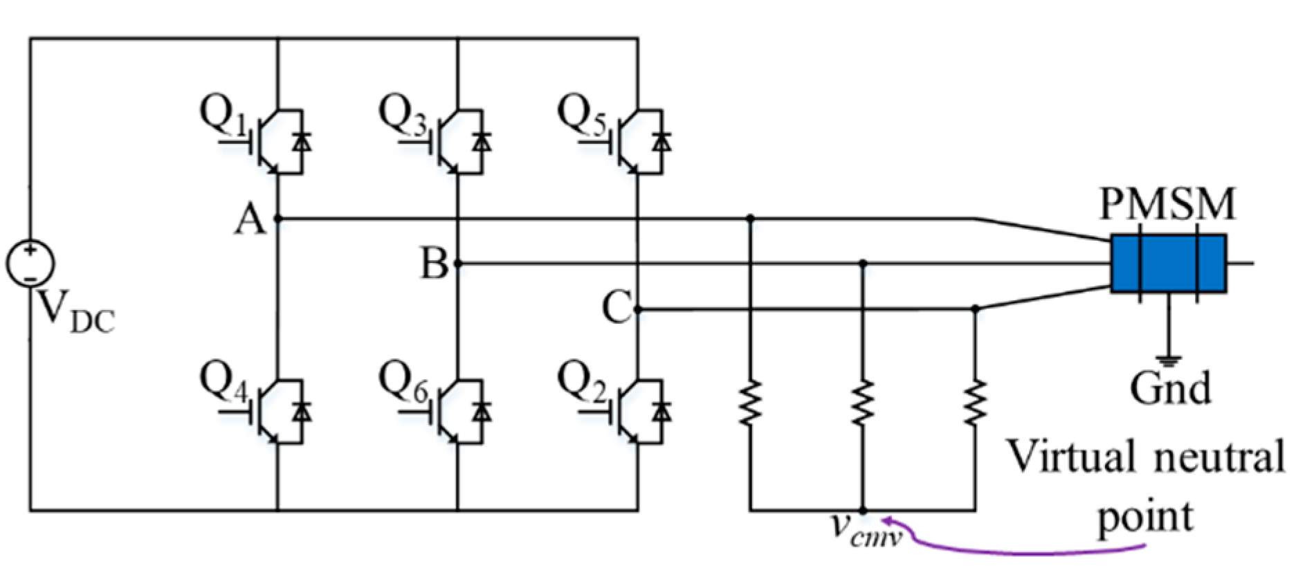
Figure 2 shows a PMSM being operated by a basic inverter topology that is commonly used in VSDs. As the DC-Bus voltage is switched using the sine PWM by the transistors to generate the three-phase sinusoidal voltage and operate the motor, it also results in a net voltage v c m v at the virtual neutral point with respect to the ground. This resultant voltage due to PWM switching at the virtual neutral point is called the common mode voltage. The rise and fall times in the CMV correspond to the equivalent frequencies of f Hz given by Equation (1) [24].
f = 1 π t r
where t r is the rise time of a PWM pulse. Thus, a 150 ns t r of CM200rx-12A corresponds to frequencies of 2.12 MHz. A virtual neutral point is created in the diagram to elaborate the common mode voltage. However, the virtual neutral point in Figure 2 acts the same as the winding’s neutral point for a Y-connected motor [25,26]. Common mode voltage is expressed as:
v c m v = U a g + U b g + U c g 3
where U a g , U b g , and U c g are the motor line voltages with respect to the ground.
At high frequencies, the motor response becomes capacitive in nature and Figure 3a shows the high frequency parasitic capacitive model of the motor and Figure 3b describe the parasitic capacitance locations with respect to the motor geometry. The shaft voltage that appears at the motor shaft to the motor ground is calculated by capacitive voltage divider action, which is given by the equation below.
ν b = C w r · ν cmv C b + C w r + C s r
where ν b , ν cmv , C w r , C b , and C s r are shaft voltage, common mode voltage, winding-to-rotor capacitance, bearing capacitance, and stator-to-rotor capacitance, respectively. C b is the parallel combination of the C b , D E and C b , N D E i.e., C b = C b , D E + C b , N D E . In Equation (3), the ratio ν b / ν c m v is called the bearing voltage ratio (BVR) and is considered to be the key parameter for occurrence of the EDM bearing currents [27].

3. Measurements of Motor Capacitance

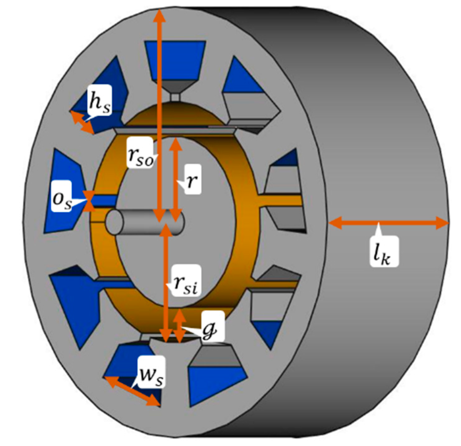
To measure the C s r capacitance, a fairly simple experiment was performed (Figure 4), as the direct measurements do not yield meaningful readings for a small 400 W motor. A direct measurement here means connecting the probes directly to the motor frame, rotor, and/or the winding. In the experiment, the rotor surface area was computed using the equation of the surface area of a cylinder.
R o t o r   s u r f a c e   a r e a = 2 π r l k + 2 π r 2
where r is the rotor radius and l k is the motor stack length. The second term on the right-hand side of Equation (4) is neglected due to the fact that the normal vector to the inner surfaces of the stator teeth is perpendicular to the normal vector of end surfaces of the rotor. Therefore, there are two surfaces that mostly contribute to the stator-to-rotor capacitance, i.e., rotor cylindrical surface area and the inner diameter of stator surface area. The rest of the surfaces are ignored since, either the surfaces are normal to each other or the distance is several times that of the airgap and, therefore, contribution of these surfaces is negligible. Since the inner diameter of the stator is known, the stator teeth surface areas and rotor surface area are converted to flat surfaces and the complete assembly of the surface areas of stator-to-rotor is considered to be a parallel plate capacitor. For the air gap, ten sheets of 80 g, A4 paper were used since each sheet thickness is considered to be 0.1 mm and the relative permittivity ε r of the paper was taken as 2.2 [28]. The thickness of the 10 sheets measured by using Vernier caliper was 1.03 mm. The LCR meter ZM2371 by nf corporation was used and reading for the experiment was 113 pF and division by relative permittivity of paper gives the capacitance of, 51.2 pF, which is the capacitance with air as the dielectric medium and is the case in stator-to-rotor assembly as well. A load of 2.5 kg was used to make the surfaces flat and the reading more reliable. Using the equation derived in Reference [27] for the calculation of C s r , the measured and calculated values only differ by <4%. Furthermore, if Carter factor is omitted from the equation in Reference [27], the C s r value matches with that of Equation (4).
Bearing capacitance, C b , is calculated using Equation (5).
C b = 0.5 ε r ε 0 A H h l b
where ε r , A H , and h l b is the permittivity of the lubricant, Hertzian contact area, and the lubricant thickness of the bearing [27]. Deep groove ball bearing 6202 has Inner Dimension 15 mm × Outer Dimension 35 mm × Width 11 mm and is designed for high rotational speeds and high dynamic loads. Similarly, 6201 has Inner Dimension 12 mm × Outer Dimension 32 mm × Width 10 mm. For non-drive-end 6201, drive-end 6202 bearings, lubricant permittivity is 3, Hertzian contact area is 5.0265 × 10 7 m 2 , 6.4757 × 10 7 m 2 , and h l b is 2 µm while C b is 7.35 pF [14]. C w r is calculated based on the method presented in Reference [29] and is 7.45 pF. With the measured and calculated values of the motor capacitances, the BVR is 11.3% and the capacitances are shown in Table 1.

4. Csr as a Compound Dielectric Capacitor and Shaft Voltage Reduction

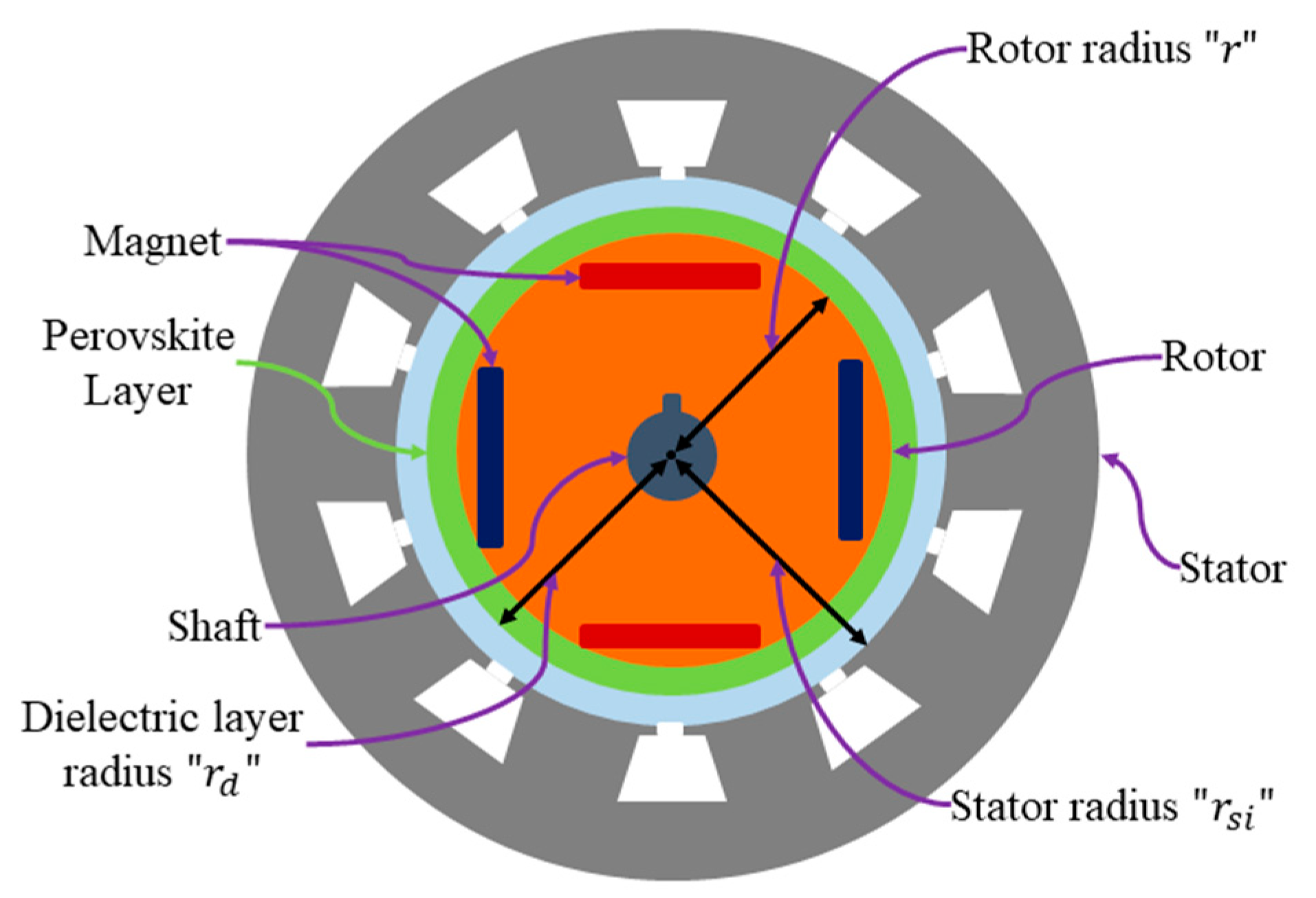
Stator-to-rotor capacitance, C s r , in the denominator of the capacitive voltage divider can be considered as a concentric cylindrical capacitor, as shown in Figure 5. Thus, an increase in the C s r will result in reduction of the shaft voltage. Therefore, to increase C s r , the rotor is coated with a thin layer of a dielectric material with high relative permittivity such as Strontium Titanate (SrTiO3) or Barium Titanate (BaTiO3 or BTO) [30,31,32]. The coated rotor and the stator together form the compound concentric capacitor that increases the C s r capacitance multiple times. The stator slot opening is neglected and the capacitance of a compound dielectric cylindrical capacitor is given by Equation (6) [33].
C s r =   2 π ε r 1 ε r 2 l k ln ( r d / r )   +   ε r 1 ln ( r s i / r d )
where ε r 1 , ε r 2 , r , r d , r s i , and l k is the permittivity of the dielectric, permittivity of the free space, rotor radius, radius of the dielectric layer, stator inner radius, and motor stack length, respectively.
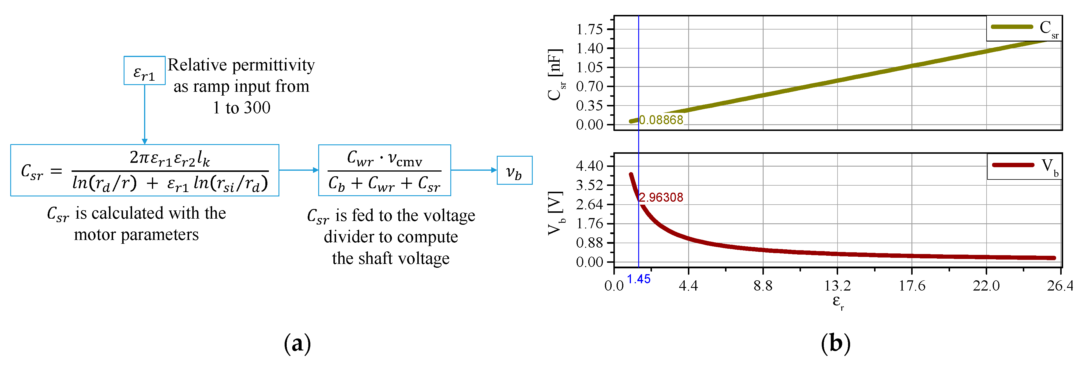
A Simulink simulation is performed where shaft voltage is plotted against the variations in C s r in Figure 6a. C s r increases as relative permittivity of the dielectric, ε r 1 , varies linearly as a ramp function with the slope set to 1. For demonstration purposes and for the effectiveness of the method, CMV is considered as a constant supply of 41 V as the bus voltage of the inverter is 41 V as well.
Simulation results show that, with an increase in ε r 1 of the dielectric material, the shaft voltage decreases as a square relationship, which is depicted in Figure 6b. The vertical cursor is set to ε r 1 = 1.45 to show the minimum value for the relative permittivity for which shaft voltage drops below the 3V mark, which is the threshold voltage for the bearing lubricant. The simulation only shows the increase in C s r and not C w r , since the shape of winding is very complex and distance is many times that of the motor air gap, and, therefore, the effect of C w r is not as prominent as C s r ’s.

5. Motor with Normal and Increased Length of the Stator Tooth Wedge

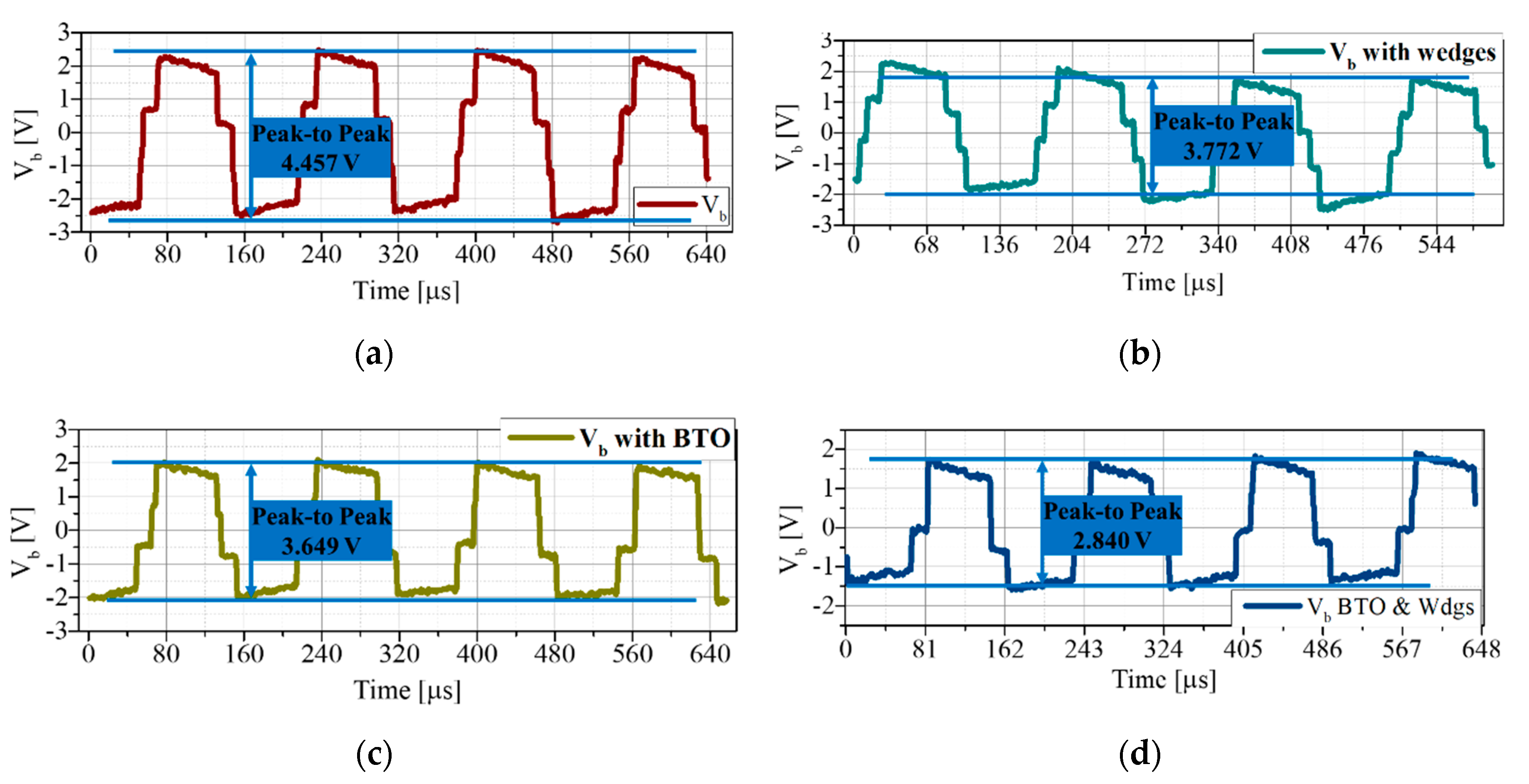
Our lab has designed several PMSMs to mitigate the shaft voltage [29]. From Equation (3), it is apparent that the winding to rotor capacitance is the main cause of the charging up of the bearing capacitance. Thus, a motor was designed to show that introducing a stator tooth wedge in the PMSM motor will result in an increase of the distance of the winding from the rotor. Therefore, winding to rotor capacitance is decreased and shaft voltage is reduced. Experiments were performed on the two motors with and without stator tooth wedges. A LeCroy WAVESURFER 44MXs-B Oscilloscope was used for voltage measurements. In order to have comparable readings of the two motors, motor speed, input DC bus voltage, and the oscilloscope dimensions were kept the same. A 400W 6-pole, 9-slot motor is used for the experimentation and motor dimensions given in Table 2. Experiments were performed at 1000 rpm and DC bus voltage was set to 55 V. The oscilloscope time axis was set to 100 μs/div, while, for shaft voltage, the amplitude setting was 5 V/div. Oscilloscope waveforms were saved in a USB drive using the waveform save function. Afterward, the waveforms were carefully processed to eliminate the DC bias and a constant slope from the waveforms using MS Excel. Figure 7 shows the designed motors and shaft voltage of the two motors with and without the stator tooth wedges. Afterward, upon removal of the DC bias, there is still a DC level difference between the two motors. Thus, to minimize the comparison error, peak- to-peak values are considered and, furthermore, the peak value is an average of all the points in the high level of the waveform. A similar method is followed for the low level as well. Mean peak-to-peak shaft voltage of the motor without stator tooth wedges is 4.457 V and, for the motor with increased tooth wedges, it is 3.772 V. The comparison shows that mean peak-to-peak shaft voltage is reduced by 0.685 V, i.e., a reduction of 15.4%. BVR becomes 9.2%, which may result in a reduction of EDM bearing currents and, hence, will improve the reliability of the overall system.

6. Experiments of the Motor with and Without a Rotor BTO Layer

6.1. Rotor with the BTO Layer and Stator Without Tooth Wedges

Experiments are performed in order to demonstrate the effectiveness of the idea of shaft voltage reduction through the increase of C s r by a layer of BTO on the rotor. The BTO layer composition is given in Table 3. The BTO powder with a grain size <3 µm was purchased from MERCK and mixed with a general purpose adhesive and a solution of 13% BTO by volume was prepared to coat the rotor. The BTO was coated on the rotor and on a 2-cm copper plate as well. The copper plates were used to measure the relative permittivity of the BTO solution. Therefore, a set of copper plates as a parallel plate capacitor had paper as dielectric material and another with BTO solution as dielectric material. The capacitance of the capacitors with paper and with BTO were measured and relative permittivity of the BTO solution was determined to be approximately 5. The BTO solution had decreased relative permittivity as compared to the pure Barium Titanate [34]. Rotor with and without BTO layer are shown in Figure 8.
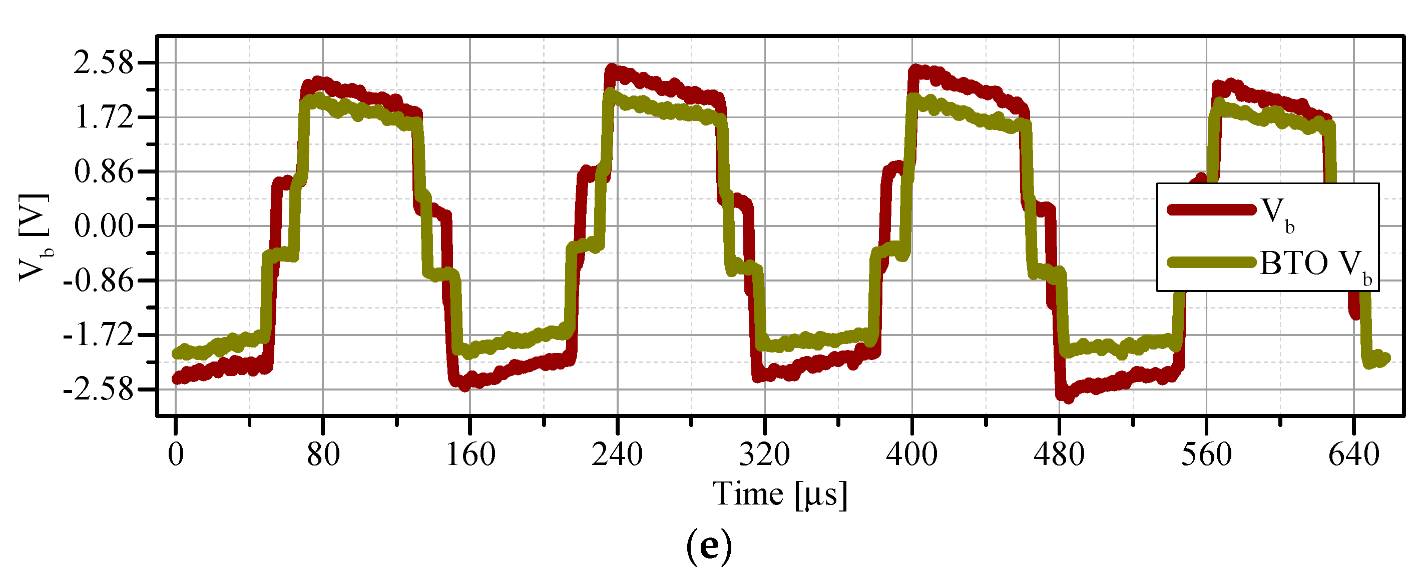
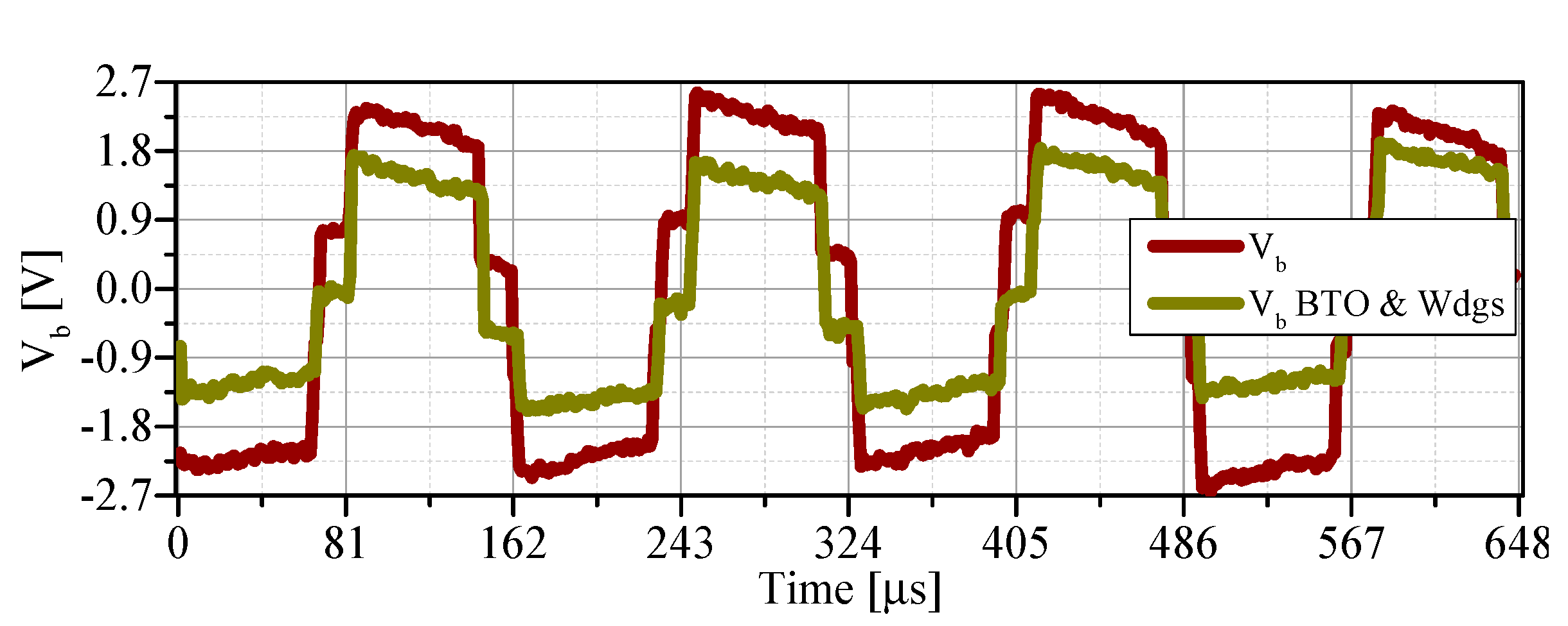
Experiments were performed with a specially constructed motor having end plates made of plastic. Thus, shaft voltage is conveniently measured. Motor speed was set at 50 Hz for all the measurements and experimental scheme is as shown in Figure 8c. The inverter is custom made by the Advanced Drive Technology (ADT). Switching frequency of the inverter was set at 6 kHz and was the same for all the experiments. A mercury contact slip ring m130k was used for the connection of the probe to the motor shaft. Rotor without the BTO layer was first used to measure the CMV and shaft voltage. Afterward, rotor with the BTO layer was utilized while keeping the stator same for both experiments. The average BTO layer thickness was 0.43 mm. The shaft voltage measured for the motor with and without the BTO layer is shown in Figure 8e. Since the peak values are not uniform, all the peak values were averaged and mean peak-to-peak value was considered for the comparison of the two shaft voltages. Shaft voltage without a BTO layer was V M P P = 4.457   V and shaft voltage for the motor with the BTO layer was V B T O M P P = 3.649   V . This is an improvement of 0.808 V, which is 18% reduction in the shaft voltage of the motor and BVR is reduced to 8.9%, which shows the anticipated improvement [35]. With the 18% percent reduction in the shaft voltage (bearing voltage) and improved BVR, it is expected that it will improve the motor system’s reliability, bearing life will be extended, and maintenance costs will be reduced.

6.2. Rotor with BTO Layer and Stator with Tooth Wedges

An experiment is performed by combining the BTO layer with the stator tooth wedges, which results in the least amount of the motor shaft voltage. Results of the experiments are shown in Figure 9. As can be seen in Figure 9, the difference in the shaft voltages becomes very prominent. The comparison of the voltages is between shaft voltage of the motor without the BTO layer and without the stator tooth wedges and the motor with the rotor BTO layer and the stator tooth wedges. Shaft voltage without the rotor BTO layer and without the stator tooth wedges is V M P P = 4.457   V , while, with the rotor BTO layer and with the stator tooth wedges, shaft voltage is V B T O & W d g s M P P = 2.84   V . In terms of the amplitudes, it is a reduction of 37% and the BVR becomes 6.9%. These results show effectiveness and consistency in terms of the application of the BTO layer to the rotor and reduction of the shaft voltage. Table 4 tabulates the results of the different methods and the respective shaft voltage.

6.3. Back EMF of the Motor with and without the Rotor BTO Layer

A comparison of the back electromotive force (BEMF) of the motor with the rotor BTO layer and without the rotor BTO layer is performed. The comparison is done at two speeds, i.e., 1000 rpm and 2000 rpm, respectively. The experimental results are shown in Figure 10. The small speed variations in the plots may be due to minute variations in the applied voltage to the prime mover during experimentation. As is evident from the plots that traces match exactly, it can be inferred that the rotor BTO layer does not affect design and key parameters of the motor.

6.4. A Comparison of the Simulation and Experimental Results

The simulation results show an exponential decrease in the shaft voltage as the dielectric constant value increases linearly. That is because the stator-to-rotor capacitance is considered as a compound capacitor and, in the simulation, only stator-to-rotor capacitance is dependent on the BTO layer. Therefore, the shaft voltage reduction is very pronounced in the simulation. However, during the experiments, it was learned that winding-to-rotor capacitance also increases in value by the BTO layer and the increase in the winding-to-rotor capacitance is 3.45-times that of the no-layer value (as determined by the experiments). The stator-to-rotor capacitance increase is five times to that of the no layer value. Thus, this provides an 18% and 37% reduction of the shaft voltage by the application of the BTO layer, respectively.
Oscilloscope captured data of the experiments is shown in Figure 11. As explained earlier, the results shown in figures are experimental results. However, they were processed to remove the slope and adjust the DC-level of the waveforms to mimic the actual industry drive systems.

7. Explanation for the Shaft Voltage Mitigation

As the experiment of the motor with the BTO layer shows reduction in the shaft voltage of the motor, its related theory is explained. Figure 12 (not drawn to scale) shows a motor model with the respective dimensions in order to elaborate in detail. Since the motor parasitic capacitances are part of the motor geometry and the shapes of the concerned parasitic capacitance geometries are very complex, parasitic capacitances involved in the BVR of the motor are simplified and only the related surface areas and surface distances are discussed here. For description purposes, an analogy to a parallel plate capacitor is used. In a parallel plate capacitor, the capacitance is directly proportional to the overlapped area of the parallel plates and is inversely proportional to the distance between the plates. The stator to rotor capacitance is between the rotor surface and the stator surface, which is color coded as orange in Figure 12 and the two surfaces are only 1 mm apart. In comparison to the stator-to-rotor capacitance, the winding to rotor capacitance consists of the winding in the slots and the rotor surface. For the sake of simplicity, the blue areas in Figure 12 are of the winding and are considered to be of the surface of winding-to-rotor capacitance and the other surface is the rotor surface, which is orange. Since, the rotor BTO layer should increase both the stator-to-rotor and winding-to-rotor capacitance, the winding-to-rotor capacitance is constrained due to the stator slot openings and, furthermore, winding-to-rotor distance is much greater than that of the stator-to-rotor distance. Thus, it can be inferred that increase in stator-to-rotor capacitance by the application of the BTO layer is more than the winding-to-rotor capacitance and, in consequence, reduction of the shaft voltage.

8. Conclusions

The simulation results show that, with the application of the dielectric material layer with high relative permittivity, the stator-to-rotor assembly can be considered as a compound cylindrical capacitor having high capacitance, and, therefore, will result in reduced shaft voltage (bearing voltage) and may result in anticipated elimination of the EDM bearing currents. BEMF measured for the motor with the BTO layer matches exactly that of the motor without the BTO layer, showing that the layer does not affect the motor design and magnetics. Moreover, experiments were conducted by applying BTO solution to the rotor and the results show that, by application of the BTO layer, the shaft voltage reduces by 18%. Furthermore, the shaft voltage reduction is up to 37% for the motor by having a BTO layer and stator tooth wedge techniques combined.
Future work may focus on a BTO layer on the inner surfaces of the stator teeth. The stator teeth layer will not cause an increase in winding to rotor capacitance and the shaft voltage may further be reduced. Furthermore, melting point of BTO is 1625 °C. With such a high melting point temperature, a layer of pure BTO (100 µm) may be plasma sprayed on the rotor surface. Pure BTO has relative permittivity of several thousands and may provide additional reduction in the shaft voltage. Additionally, the layer thickness of 100 µm will not affect the motor design.

Author Contributions

Conceptualization, M.A.; Investigation, M.A. and J.-H.I.; Methodology, M.A.; Validation, M.A.; Writing-Review & Editing, M.A. and J.-H.I.; Supervision, J.H. All authors have read and agree to the published version of the manuscript.

Funding

This work was supported by Industrial Strategic Technology Development Program of Korea Evaluation Institute of Industrial Technology (KEIT) (No. 20006633 and No. 20002745).

Conflicts of Interest

The authors declare no conflict of interest.

References

  1. Li, Y.; Lin, H.; Huang, H.; Chen, C.; Yang, H. Analysis and Performance Evaluation of an Efficient Power-Fed Permanent Magnet Adjustable Speed Drive. IEEE Trans. Ind. Electron. 2019, 66, 784–794. [Google Scholar] [CrossRef]
  2. Durocher, D.B.; Thompson, C. Medium-Voltage Adjustable-Speed Drives Upgrade: Delivering Operational Benefits for a Steel Mill Runout Table Cooling System. IEEE Ind. Appl. Mag. 2019, 25, 34–43. [Google Scholar] [CrossRef]
  3. Choi, U.-M.; Jørgensen, S.; Blaabjerg, F. Impact of Cooling System Capacity on Lifetime of Power Module in Adjustable Speed Drives. IEEE J. Emerg. Sel. Top. Power Electron. 2019, 7, 1768–1776. [Google Scholar] [CrossRef]
  4. Ruffo, R.; Guglielmi, P.; Armando, E. Inverter Side RL Filter Precise Design for Motor Overvoltage Mitigation in SiC-Based Drives. IEEE Trans. Ind. Electron. 2020, 67, 863–873. [Google Scholar] [CrossRef]
  5. Muetze, A. Bearing Currents in Inverter-Fed AC-Motors. Ph.D. Thesis, Technische Universität Darmstadt, Darmstadt, Germany, 2004. [Google Scholar]
  6. SKF Group. Rolling Bearings and Seals in Electric Motors and Generators; SKF Group: Gothenburg, Sweden, August 2013. [Google Scholar]
  7. Wittek, E.; Kriese, M.; Tischmacher, H.; Gattermann, S.; Ponick, B.; Poll, G. Capacitance of bearings for electric motors at variable mechanical loads. In Proceedings of the 2012 XXth International Conference on Electrical Machines, Marseille, France, 2–5 September 2012; pp. 1602–1607. [Google Scholar]
  8. Wittek, E.; Kriese, M.; Tischmacher, H.; Gattermann, S.; Ponick, B.; Poll, G. Capacitances and lubricant film thicknesses of motor bearings under different operating conditions. In Proceedings of the The XIX International Conference on Electrical Machines—ICEM 2010, Rome, Italy, 6–8 September 2010; pp. 1–6. [Google Scholar]
  9. Magdun, O.; Gemeinder, Y.; Binder, A. Prevention of harmful EDM currents in inverter-fed AC machines by use of electrostatic shields in the stator winding overhang. In Proceedings of the IECON 2010—36th Annual Conference on IEEE Industrial Electronics Society, Glendale, AZ, USA, 7–10 November 2010; pp. 962–967. [Google Scholar]
  10. Erdman, J.M.; Kerkman, R.J.; Schlegel, D.W.; Skibinski, G.L. Effect of PWM inverters on AC motor bearing currents and shaft voltages. IEEE Trans. Ind. Appl. 1996, 32, 250–259. [Google Scholar] [CrossRef]
  11. Busse, D.F.; Erdman, J.M.; Kerkman, R.J.; Schlegel, D.W.; Skibinski, G.L. The effects of PWM voltage source inverters on the mechanical performance of rolling bearings. IEEE Trans. Ind. Appl. 1997, 33, 567–576. [Google Scholar] [CrossRef]
  12. Holbert, K.E.; Lin, K.; Karady, G.G. Enhancement of Electric Motor Reliability through Condition Monitoring. IFAC Proc. Vol. 2006, 39, 255–260. [Google Scholar] [CrossRef]
  13. von Jauanne, A.; Zhang, H. A dual-bridge inverter approach to eliminating common-mode voltages and bearing and leakage currents. IEEE Trans. Power Electron. 1999, 14, 43–48. [Google Scholar] [CrossRef]
  14. NSK. Rolling Bearings; NSK: Tokyo, Japan, March 2005. [Google Scholar]
  15. Wang, F. Motor shaft voltages and bearing currents and their reduction in multilevel medium-voltage PWM voltage-source-inverter drive applications. IEEE Trans. Ind. Appl. 2000, 36, 1336–1341. [Google Scholar] [CrossRef]
  16. Alger, P.L.; Samson, H.W. Shaft currents in electric machines. J. Am. Inst. Electr. Eng. 1923, 42, 1325–1334. [Google Scholar] [CrossRef]
  17. Qin, C.; Zhang, C.; Xing, X.; Li, X.; Chen, A.; Zhang, G. Simultaneous Common-Mode Voltage Reduction and Neutral-Point Voltage Balance Scheme for the Quasi-Z-Source Three-Level T-Type Inverter. IEEE Trans. Ind. Electron. 2020, 67, 1956–1967. [Google Scholar] [CrossRef]
  18. Qin, C.; Zhang, C.; Chen, A.; Xing, X.; Zhang, G. A Space Vector Modulation Scheme of the Quasi-Z-Source Three-Level T-Type Inverter for Common-Mode Voltage Reduction. IEEE Trans. Ind. Electron. 2018, 65, 8340–8350. [Google Scholar] [CrossRef]
  19. Samanes, J.; Gubia, E.; Juankorena, X.; Girones, C. Common-Mode and Phase-to-Ground Voltage Reduction in Back-to-Back Power Converters with Discontinuous PWM. IEEE Trans. Ind. Electron. 2020, 67, 7499–7508. [Google Scholar] [CrossRef]
  20. Mishra, P.; Maheshwari, R. Design, Analysis, and Impacts of Sinusoidal LC Filter on Pulsewidth Modulated Inverter Fed-Induction Motor Drive. IEEE Trans. Ind. Electron. 2020, 67, 2678–2688. [Google Scholar] [CrossRef]
  21. Han, D.; Morris, C.T.; Sarlioglu, B. Common-Mode Voltage Cancellation in PWM Motor Drives with Balanced Inverter Topology. IEEE Trans. Ind. Electron. 2017, 64, 2683–2688. [Google Scholar] [CrossRef]
  22. Gerber, S.; Wangi, R.-J. Reduction of Inverter-Induced Shaft Voltages Using Electrostatic Shielding. In Proceedings of the 2019 Southern African Universities Power Engineering Conference/Robotics and Mechatronics/Pattern Recognition Association of South Africa (SAUPEC/RobMech/PRASA), Bloemfontein, South Africa, 28–30 January 2019; pp. 310–315. [Google Scholar]
  23. Lee, S.-T.; Park, J.-K.; Jeong, C.-L.; Rhyu, S.-H.; Hur, J. Shaft-to-Frame Voltage Mitigation Method by Changing Winding-to-Rotor Parasitic Capacitance of IPMSM. IEEE Trans. Ind. Appl. 2019, 55, 1430–1436. [Google Scholar] [CrossRef]
  24. Zhong, E.; Lipo, T.A.; Rossiter, S. Transient modeling and analysis of motor terminal voltage on PWM inverter-fed AC motor drives. In Proceedings of the Conference Record of 1998 IEEE Industry Applications Conference. Thirty-Third IAS Annual Meeting (Cat. No.98CH36242), St. Louis, MO, USA, 12–15 October 1998; Volume 1, pp. 773–780. [Google Scholar]
  25. Bose, B.K. Power Electronics and Motor Drives: Advances and Trends; Elsevier: Amsterdam, The Netherlands, 2010; ISBN 978-0-08-045738-3. [Google Scholar]
  26. Rodriguez, J.; Cortes, P. Predictive Control of Power Converters and Electrical Drives; John Wiley & Sons: Hoboken, NJ, USA, 2012; ISBN 978-1-119-94264-1. [Google Scholar]
  27. Muetze, A.; Binder, A. Calculation of Motor Capacitances for Prediction of the Voltage across the Bearings in Machines of Inverter-Based Drive Systems. IEEE Trans. Ind. Appl. 2007, 43, 665–672. [Google Scholar] [CrossRef]
  28. Sirviö, P. Electrical and Dielectric Properties of Uncoated and Coated Wood-free Paper for Electrophotography. Ph.D. Thesis, Åbo Akademi University, Turku, Finland, 2016. [Google Scholar]
  29. Park, J.; Wellawatta, T.R.; Choi, S.-J.; Hur, J. Mitigation Method of the Shaft Voltage According to Parasitic Capacitance of the PMSM. IEEE Trans. Ind. Appl. 2017, 53, 4441–4449. [Google Scholar] [CrossRef]
  30. Popielarz, R.; Chiang, C.K.; Nozaki, R.; Obrzut, J. Dielectric Properties of Polymer/Ferroelectric Ceramic Composites From 100 Hz to 10 GHz. Macromolecules 2001, 34, 5910–5915. [Google Scholar] [CrossRef]
  31. McNeal, M.P.; Jang, S.-J.; Newnham, R.E. Particle size dependent high frequency dielectric properties of barium titanate. In Proceedings of the ISAF’96. Tenth IEEE International Symposium on Applications of Ferroelectrics, East Brunswick, NJ, USA, 18–21 August 1996; Volume 2, pp. 837–840. [Google Scholar]
  32. Arlt, G.; Hennings, D.; de With, G. Dielectric properties of fine-grained barium titanate ceramics. J. Appl. Phys. 1985, 58, 1619–1625. [Google Scholar] [CrossRef] [Green Version]
  33. Theraja, B.L. Textbook of Electrical Technology; Chand: New Dehli, India, 2008; ISBN 978-81-219-2441-2. [Google Scholar]
  34. Mao, Y.; Zhou, H.; Wong, S.S. Synthesis, Properties, and Applications of Perovskite- Phase Metal Oxide Nanostructures. Mater. Matters 2010, 5, 50. [Google Scholar]
  35. Frost, N.E.; McGrath, P.B. Dielectric properties of barium titanate and alumina filled epoxy. In Proceedings of the 1995 Conference on Electrical Insulation and Dielectric Phenomena, Virginia Beach, VA, USA, 22–25 October 1995; pp. 564–567. [Google Scholar]
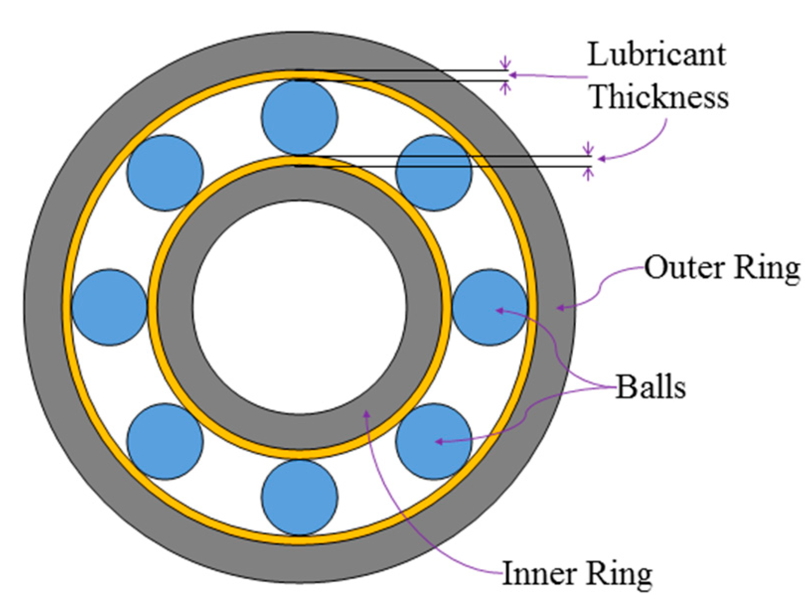
Figure 1. A deep grooved ball bearing, showing parts and the lubricant layer.
Energies 13 05762 g001
Figure 2. A common inverter topology used in most of the drives.
Energies 13 05762 g002
Figure 3. Motor behavior at high frequencies. (a) High frequency capacitive model of an electric motor. (b) Location of the parasitic capacitances with respect to motor geometry.
Energies 13 05762 g003
Figure 4. Experimental scheme to measure C s r . (a) Diagram of the experimental scheme. (b) Thin copper tape was used to represent capacitance surfaces.
Energies 13 05762 g004
Figure 5. Stator to rotor concentric capacitor with compound dielectric. ε r 2 = ε 0 since the second medium constitutes of air.
Energies 13 05762 g005
Figure 6. (a) Block diagram of the simulation. (b) Increase in capacitance C s r and decrease in shaft voltage V b with respect to relative permittivity ε r 1 .
Energies 13 05762 g006
Figure 7. Stators of the designed motors and corresponding motor responses. (a) Stator with a normal tooth wedge. (b) Stator with an increased tooth wedge. (c) Comparison of the shaft voltage of the two motors.
Energies 13 05762 g007
Figure 8. Experimental setup and measuring shaft voltage of the PMSM. (a) Rotor without BTO layer. (b) Rotor with BTO layer. (c) Block diagram of the layout of the experiment. (d) Experimental equipment. (e) Shaft voltage, V b , of the motor with and without a rotor BTO layer.
Energies 13 05762 g008aEnergies 13 05762 g008b
Figure 9. Comparison of the shaft voltage (bearing voltage) of the motor. Red trace is of the motor without the rotor BTO layer and without stator tooth wedges. Yellow trace is of the motor with the rotor BTO layer and stator tooth wedges.
Energies 13 05762 g009
Figure 10. BEMF of the motor with and without rotor BTO layer. (a) BEMF at 1000 r/min. (b) BEMF at 2000 r/min.
Energies 13 05762 g010
Figure 11. Shaft voltage (bearing voltage) of the motor. (a) Shaft voltage of the motor without a rotor BTO layer and without stator tooth wedges. (b) Shaft voltage of the motor without a rotor BTO layer and with stator tooth wedges. (c) Shaft voltage of the motor with the rotor BTO layer and without stator tooth wedges. (d) Shaft voltage of the motor with the rotor BTO layer and with stator tooth wedges.
Energies 13 05762 g011
Figure 12. Motor and the parasitic capacitance respective interactive areas.
Energies 13 05762 g012
Table 1. Motor parasitic capacitances (calculated).
Capacitance NameSymbolCapacitance Value [pF]
Stator-to-Rotor C s r 53.2
Winding-to-Rotor C w r 7.45
Bearing Capacitance C b 7.35
Table 2. Dimensions of the motor used for experiments.
Motor ParameterSymbolMeasurements [mm]
Rotor radius r 27
Stator inner radius r s i 28
Stator outer radius r s o 50
Air gap length 1
Stack length l k 40
Slot Opening o s 3
Slot Width w s 12
Slot Height h s 13
Table 3. BTO layer composition.
MaterialSymbolValue
Barium Titanate (BTO)BaTiO315.1 g
Adhesive 16 g
Dielectric constant of the BTO-Adhesive solution ε r 1 5
Dielectric constant of pure BTO ε r 1000 to 10,000 [33]
Table 4. BVR improvement w.r.t. shaft voltage reduction method.
MotorVb
[V]
Reduction
in Vb [%]
BVR
[%]
Motor without BTO and without stator wedges4.457011
Motor without BTO and with stator wedges3.77215.49.2
Motor with BTO and without stator wedges3.64918.18.9
Motor with BTO and with stator wedges2.84036.36.9
Publisher’s Note: MDPI stays neutral with regard to jurisdictional claims in published maps and institutional affiliations.