Abstract
Carbon emissions reduction via the increase of sustainable energy sources in need of storage defines chemicals such as ammonia as one of the promising solutions for reliable power decarbonisation. However, the implementation of ammonia for fuelling purposes in gas turbines for industry and energy production is challenging when compared to current gas turbines fuelled with methane. One major concern is the efficiency of such systems, as this has direct implications in the profitability of these power schemes. Previous works performed around parameters prediction of standard gas turbine cycles showed that the implementation of ammonia/hydrogen as a fuel for gas turbines presents very limited overall efficiencies. Therefore, this paper covers a new approach of parameters prediction consisting of series of analytical and numerical studies used to determine emissions and efficiencies of a redesigned Brayton cycle fuelled with humidified ammonia/hydrogen blends. The combustion analysis was done using CHEMKIN-PRO (ANSYS, Canonsburg, PA, USA), and the results were used for determination of the combustion efficiency. Chemical kinetic results denote the production of very low NOx as a consequence of the recombination of species in a post combustion zone, thus delivering atmospheres with 99.2% vol. clean products. Further corrections to the cycle (i.e., compressor and turbine size) followed, indicating that the use of humidified ammonia-hydrogen blends with a total the amount of fuel added of 10.45 MW can produce total plant efficiencies ~34%. Values of the gas turbine cycle inlet parameters were varied and tested in order to determine sensibilities to these modifications, allowing changes of the analysed outlet parameters below 5%. The best results were used as inputs to determine the final efficiency of an improved Brayton cycle fuelled with humidified ammonia/hydrogen, reaching values up to 43.3% efficiency. It was notorious that humidification at the injector was irrelevant due to the high water production (up to 39.9%) at the combustion chamber, whilst further research is recommended to employ the unburned ammonia (0.6% vol. concentration) for the reduction of NOx left in the system (~10 ppm).
1. Introduction
Recently, the International Energy Agency has included ammonia as part of the mix of fuels that will be employed in the near future [1]. The motion comes as ammonia can originate from fossil fuels as well as from most sustainable sources [2]. Since the combustion products consist mostly of water and nitrogen, the implementation of ammonia fuelling has a potential for zero-carbon power production with significantly decreased NOx emissions. Current analyses have been performed on automotive engines [3], while power generation has recently gained interest in various countries [4]. However, there is a lack of studies for the efficient implementation of this technology, thus requiring further works to attract industrial support [5,6].
Gas turbine systems are significantly implemented in large-scale power generation and represent a unique technology to produce energy using a great variety of fuels. Current gas turbine combustion is based on swirling flows application that can provide stabilization and anchoring to the flame due to coherent structures produced by enhanced fluid dynamics [7]. Application of swirling flows in systems powered by ammonia shows great impact on stabilization of a fuel with low reactivity [8]. Concurrently, researchers are assessing this technology by employing pure ammonia/air blends for premixed combustion. One of the published studies shows that maximum burning velocities for ammonia are lower than those of hydrocarbon flames with value of less than 7 cm/s for the case of unstretched laminar flames, decreasing with the increase in the initial mixture pressure [9]. Another study shows that minimal values of NO and unburnt NH3 emissions, in the order of 200 ppm, could be reached at the equivalence ratio of 1.2, even though there is still an unburnt H2 emission of 6% volumetric exhaust flow [10]. Other groups are working on the development of mechanisms for analyses of methane-ammonia blends, showing greater stability for large power production. Xiao H. et al. compared five different reduced mechanisms of the well-known Konnov’s mechanism and tested delay times for validation. Further analyses were conducted under high-pressure conditions using ammonia/methane mixtures [11]. The results showed feasible combustion with improved emissions at relevant industrial conditions. Valera-Medina A. et al. have analysed generic tangential burners to determine flame stability and emissions at different equivalence ratios for ammonia/methane blends, showing that fully premixed injection is not appropriate, as well as that at medium swirl numbers high flame instabilities can occur, therefore recommending lower swirl and different injection strategies [12]. In other study, Xiao H. et al. showed that the mechanisms of Tian and Teresa exhibit the best accuracy over a large range of conditions [13], and similarly, denoted the potential of ammonia blending for large power generation. However, the main problem with this blend is that the carbon-based source, i.e., methane, is still present.
A promising solution to noncarbon combustion of ammonia is co-firing it with hydrogen. In this way, with hydrogen as doping agent, combustion with significant efficiency and relative high powers can be accomplished [14]. Some blends of ammonia-hydrogen combusted in premixed combustors can obtain flame velocities similar to methane. However, further studies show boundary layer flashback followed by high NOx under lean conditions due to the detrimental diffusivity of hydrogen and its high reactivity, respectively [15]. Particular to these blends, analyses of chemical kinetic mechanisms highlight the potential of using this chemical as a fuelling source, results that fall within experimental data ranges at different concentrations, equivalence ratios and pressures [16]. According to previous analyses, the optimal parameters for low NOx production are in the region of the rich combustion from 1.0 to 1.31 equivalence ratios (ER) [4]. Emissions were up to 100 ppm [6], demonstrating that ammonia can be used as a fuel. However, emissions reduction and easy fuel handling needs to be coupled with efficient energy production. Therefore, novel ammonia-hydrogen cycles need to be conceived to compete with commercial technologies with efficiencies above 30%.
In terms of efficiency, a representative way to increase gas turbine cycle power and efficiency are humidified cycles [17]. Humidified gas turbines have been seen, for a long time, as technology with great potential for high efficiency energy production, especially combined with other technologies in cogeneration and district heating or technological solutions such as water or steam recovering from exhaust gas or CO2 removal [18]. Steam-based gas turbine cycles have been employed over the years [19,20], especially for Combined Heat and Power (CHP) [21]. Humidification and steam reforming have also been used simultaneously [22,23], under various compressor stages [24], and under a great variety of conditions. To avoid combustion and ignition problems, humidified regimes need to be carefully understood [25]. The method can be utilized in CHP units while enabling cooling and heating of various streams, thus making more efficient the energy consumption/production process [26] whilst ensuring off-design operational conditions [27,28]. The application of steam injection through these methods have allowed more waste heat to be recovered from exhaust gases [29,30]. In addition, NOx can be reduced up to 1.69 times compared to dry cases [31,32]. Therefore, steam injection can be combined with other methods of heat recovery, i.e., recirculation of species, to improve efficiency and reduce fuel consumption [33,34].
Analyses of some possibilities for the use of ammonia/hydrogen mixtures via humified conditions in gas turbine have been presented in previous literature [5]. A mathematical model developed and calibrated previously has been employed for simulation of a gas turbine in extreme conditions such as OXYFUEL combustion powered by methane (OF) and innovative working fluid blends (i.e., argon/CO2/water vapour—CARSOXY) [35,36]. It must be pointed out that the purpose of the model was to determine the possibility of implementation of more complex blends, such as co-firing of the gasification gas originated from corn cob with methane at off-design conditions [37].
However, initial implementation of the model for ammonia/hydrogen blends [5] showed that such a strategy presents various limitations. As a comparison, a Dry Low NOx (DLN) methane-fuelled was also analysed. For the DLN case, the cycle predicted efficiencies 19.35%, i.e., since the system was designed for higher fuel flowrates and power values, with ~37% of the total available air flowrate in the combustion primary zone and temperatures at the gas turbine inlet of 1275 K. In comparison, first analyses of a dry ammonia-hydrogen gas turbine demonstrated only efficiencies 9.77% [5]. The significantly lower value of the cycle efficiency was consequence of the increased dilution of the flue gases. Only 15% of the total air at the compressor outlet was introduced into primary zone for the combustion process in order to maintain rich fuel-low NOx conditions. The remaining 85% was introduced into the secondary zone for dilution of the combustion products. As a consequence, the temperature of the combustion products of the ammonia/hydrogen combustion at the gas turbine outlet was only 880 K [5]. In this step of the model development, we have concluded that the reference cycle, which was designed for natural gas, is not appropriate for rich ammonia/hydrogen blends, since high value of the air mass flow obtained combustion products with lower temperatures and lower heat capacities. Therefore, it was determined that the new cycle was needed, with lower values of compressed air towards the combustion chamber.
Further studies employed a humidified cycle, increasing efficiencies up ~28.59% for 10.4 MW supplied. When off-design regimes are analysed, the gas turbine work is in function of the gas turbine polytropic efficiency. The value of gas turbine polytropic efficiency is significantly affected to the changes of the mass flowrate. Therefore, the polytropic efficiency in case of gas turbine cycle powered by ammonia-hydrogen was considered ~65% [5]. This value is significantly higher compared to dry ammonia-hydrogen combustion (i.e., ~45%), due to the change of the combustion products mass flowrate. However, the obtained values for both the humified and the dry cycles powered by ammonia-hydrogen are lower than those of the reference plant used in such a study. Therefore, the extrapolation of the polytropic efficiencies led to unresolved uncertainties. Furthermore, efficiencies ~28.59% are still low compared to new Brayton cycles, thus requiring the improvement of various parameters to meet better specifications whilst becoming attractive for industrial purposes.
Considering all limitations and challenges, further research and new approaches are necessary on improved cycles designed for humidified ammonia/hydrogen blends. Therefore, this manuscript presents a series of analytical and numerical assessments based on experimentally calibrated blends to reach efficiencies close to those obtained in current gas turbines fuelled with natural gas. Results show the type of conditions that can be applied to increase efficiencies using a blend with very low NOx emissions, which leads to opportunities for detailed studies for stable, operable and techno-economic feasibility concepts. In order to achieve competitive efficiency levels compared to current technologies, as well as compared to previous results [5], a new mathematical approach to the previously analysed model was developed using complex reaction numerical modelling.
2. Materials and Methods
2.1. Combustion
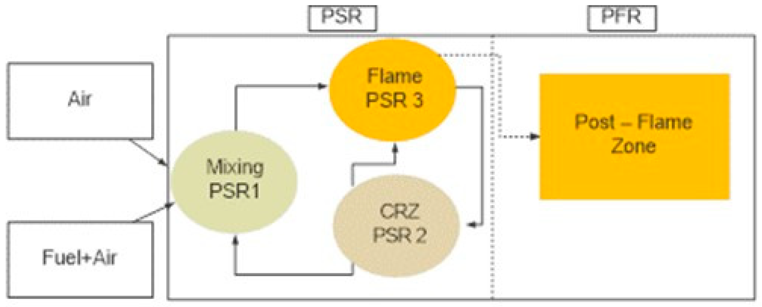
A chemical reaction network (CRN), previously calibrated and validated elsewhere [5,6], was employed to determine the combustion products in an improved Brayton cycle using humidification of a 70–30 vol.% ammonia-hydrogen blend. The blend was selected based on previous experimental campaigns [12,38]. A Perfectly Stirred Reactor (PSR) was included to simulate a swirling flame followed by a Plug Flow Reactor (PFR), which simulates a post-combustion region of 10 cm long, Figure 1. Three sub-zones were defined to accurately predict the swirling flame, i.e., a mixing region (PSR1), a central recirculation zone (CRZ, PSR2) and a shearing flow (PSR3). Residence time in the central recirculation zone was based on tests detailed elsewhere [39]. Results fed the thermodynamic analyses whilst delivering insights of the combustion process, emission profiles and radical interaction. CHEMKIN-PRO (ANSYS, Canonsburg, PA, USA) was used at 628.83 K and 9.67 bar pressure. A rich equivalence ratio (1.20) was used as suggested by Pugh et al. [40] who had previously worked with these high equivalence ratios whose excess fuel allowed further NOx mitigation downstream of the primary flame zone. An improved mechanism based on Mathieu’s mechanism was also employed [41]. Recirculation strength was determined based on previous experimental campaigns [42]. More details can be found in Xiao et al. [16].
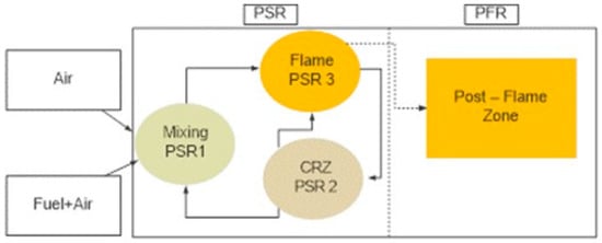
Figure 1.
Chemical reaction network. Reprinted with permission, Elsevier, 2020 [5].
Fuel flowrate was limited due to calibration limits, and set at 0.367 kg/s using a blend of 70–30% NH3–H2 vol.%. Steam was injected at 0.4 kg/kgfuel, with total 0.147 kg/s of steam at the air combustion inlet. Temperature was also kept at 628.83K. Air mass flow rates were defined at 2.260 kg/s to keep an equivalence ratio of 1.2. These conditions provided 10.45 MW of the amount of fuel added.
2.2. Gas Turbine Cycle
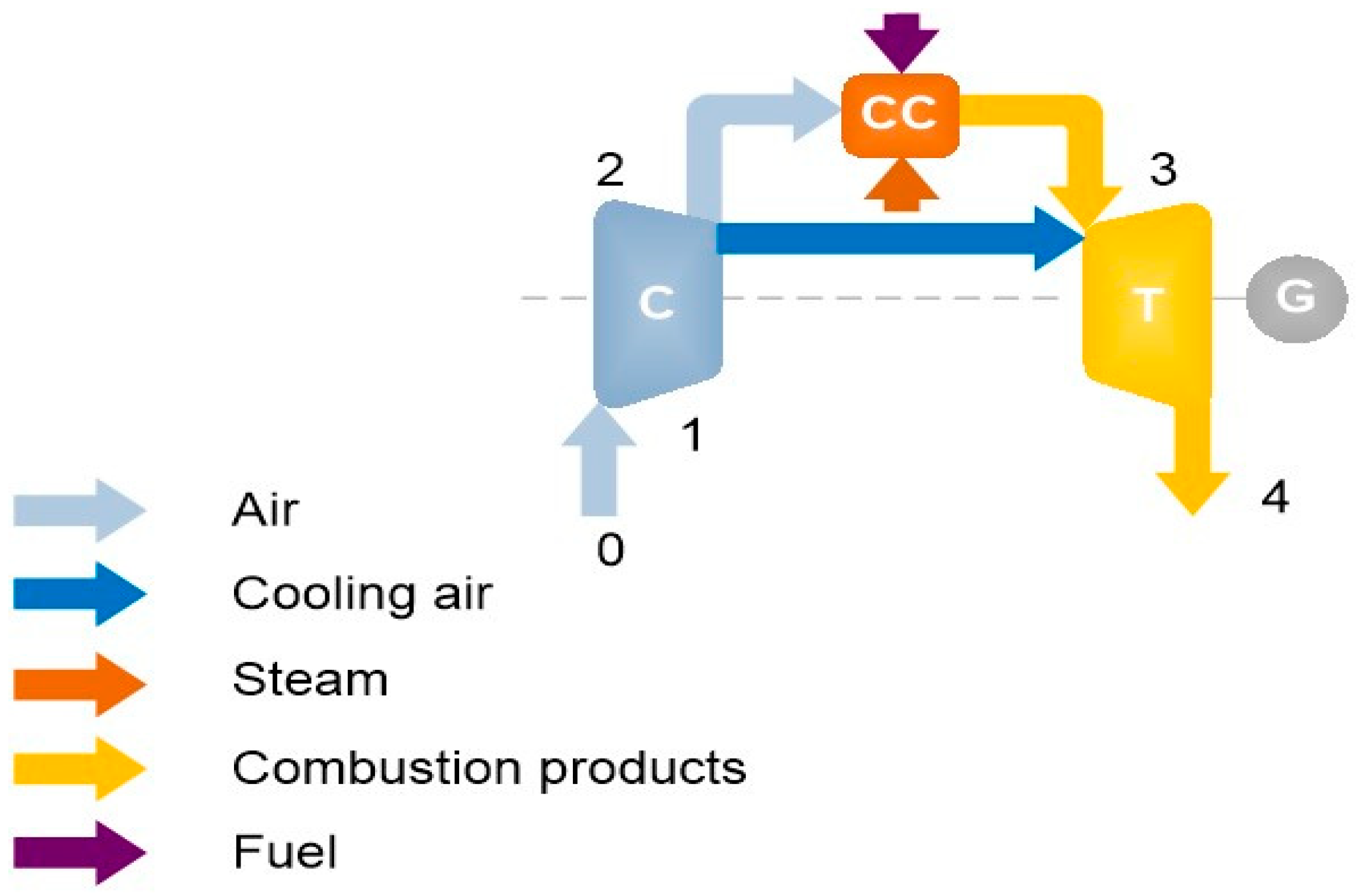
The gas turbine cycle model considered a basic humidified Brayton cycle. The cycle consisted in a compressor (i.e., for preparation of the air for combustion, dilution and gas turbine blades cooling), a combustion chamber with steam injection and a gas turbine with cooled blades, Figure 2.
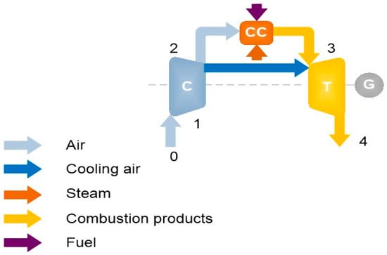
Figure 2.
Basic humidified Brayton cycle with cooling air extraction at the compressor exhaust (where C is compressor, CC combustion chamber and T is gas turbine, point 0 refers to ambient conditions, point 1—conditions at the compressor inlet, point 2—conditions at the compressor outlet or combustion chamber inlet, point 3—combustion chamber outlet or gas turbine inlet, point 4—gas turbine outlet).
Calculation of the specific compression work was done for adiabatic and polytrophic conditions in function of ratio of pressure values at the outlet and the inlet of the compressor, temperature at the compressor inlet and specific heat [43,44],
The total temperature of the air at the compressor outlet, T2t, is calculated as follows:
where the total air temperature depends on the temperature of the air at the beginning of the compression, the ratio of pressure at the outlet and the inlet of the compressor, and thermodynamic irreversibilities [43,44]. Air mass flow for cooling of the gas turbine is extracted and directed to gas turbine blades, while the rest of the compressed air is used for combustion and dilution of the combustion products.
The model analyses the continuous cooling process of the gas turbine. For the adiabatic expansion, the air distribution needs to be determined. In the reference gas turbine plant steam is introduced into the combustion chamber. The basic mathematical model [43] does not consider steam injection, therefore it is necessary to expand the simulation model and include the impact of steam on the combustion in the combustion chamber. Therefore, the ratio of the vapour mass flow and fuel mass flow at the combustion chamber inlet is introduced, where is enthalpy of steam at the combustion chamber inlet and is enthalpy of steam at the combustion chamber outlet. The useful expansion work can be calculated as follows [5],
where coefficient b was calculated from the following equation, derived from the combustion chamber energy balance [5],
The end temperature of the combustion products is obtained using the following Equation (5),
The overall cycle efficiency is determined as [38],
with as the overall efficiency (-) and the mechanical efficiency (-).
A model was developed considering humidified ammonia-hydrogen [5]. An irreversible expansion with turbine cooling was considered, and adjustments were performed using a reference gas turbine [5]. The high accuracy of the method showed relative errors under 5% [5,41].
The difference of the mathematical model compared to others is the focus on the mass balance improvement in the gas turbine cycle. Previous research [5] showed that conventional air distribution after the compressor outlet is not suitable for ammonia/hydrogen blends, and that the operation point of the ammonia/hydrogen cycle is lower than 10% load of the reference gas turbine cycle powered by natural gas. Therefore, it was necessary to determine new air distributions in the combustion chamber and mass flow values of the entire system, considering results of the ammonia/hydrogen blends. Furthermore, the capabilities of the current model enable off-design considerations that would be required for the use of humidified ammonia/hydrogen blends, not only because these blends are extremely complex (i.e., two molecules of different nature with humidified atmospheres that are reactive) but also because there are no engines currently using these blends.
Therefore, a benchmark case was initially obtained for comparison purposes. Boundary conditions were set at 1 bar and 288 K, respectively. The compressor pressure ratio was established at 10.2 using polytropic efficiencies of 80%. Simultaneously, the pressure drop in the combustion chamber was set at 3%, with combustion efficiencies of 90%. The inlet turbine temperature was established at ~1260 K (from CHEMKIN-PRO modelling). The turbine polytropic efficiency was set at 85%, with mechanical losses of 10%. Cooling air ratio was finally defined at 3.5% of air mass flow from the compressor outlet, Figure 2.
Furthermore, this study attempts to determine the sensibility of the cycle to variations in inlet parameter conditions whilst finding the best values for efficiency improvement. Investigations were carried out on compressor pressure ratio, compressor polytropic efficiency, combustion chamber pressure ratio, combustion chamber efficiency, turbine polytropic ratio, steam/fuel ratio, cooling air ratio and mechanical efficiency. The main criteria for inlet parameters variation was to change the outlet parameters. The maximum change of outlet parameters is ±5% compared to those values achieved during the calculations of the basic humidified Brayton cycle of ~34% efficiency. This efficiency value is obtained in initial simulations with inlet parameters determined for ammonia/hydrogen blend. The inlet parameter range for variation analyses was determined as a function of outlet parameters changes. Finally, the best results were employed to determine the best conditions for the cycle whilst running on humidified ammonia/hydrogen blends. Thus, conclusions are withdrawn in terms of emissions performance and efficiency outputs of the best available large power generation technology using such fuels.
3. Results
3.1. Numerical Analyses—Combustion
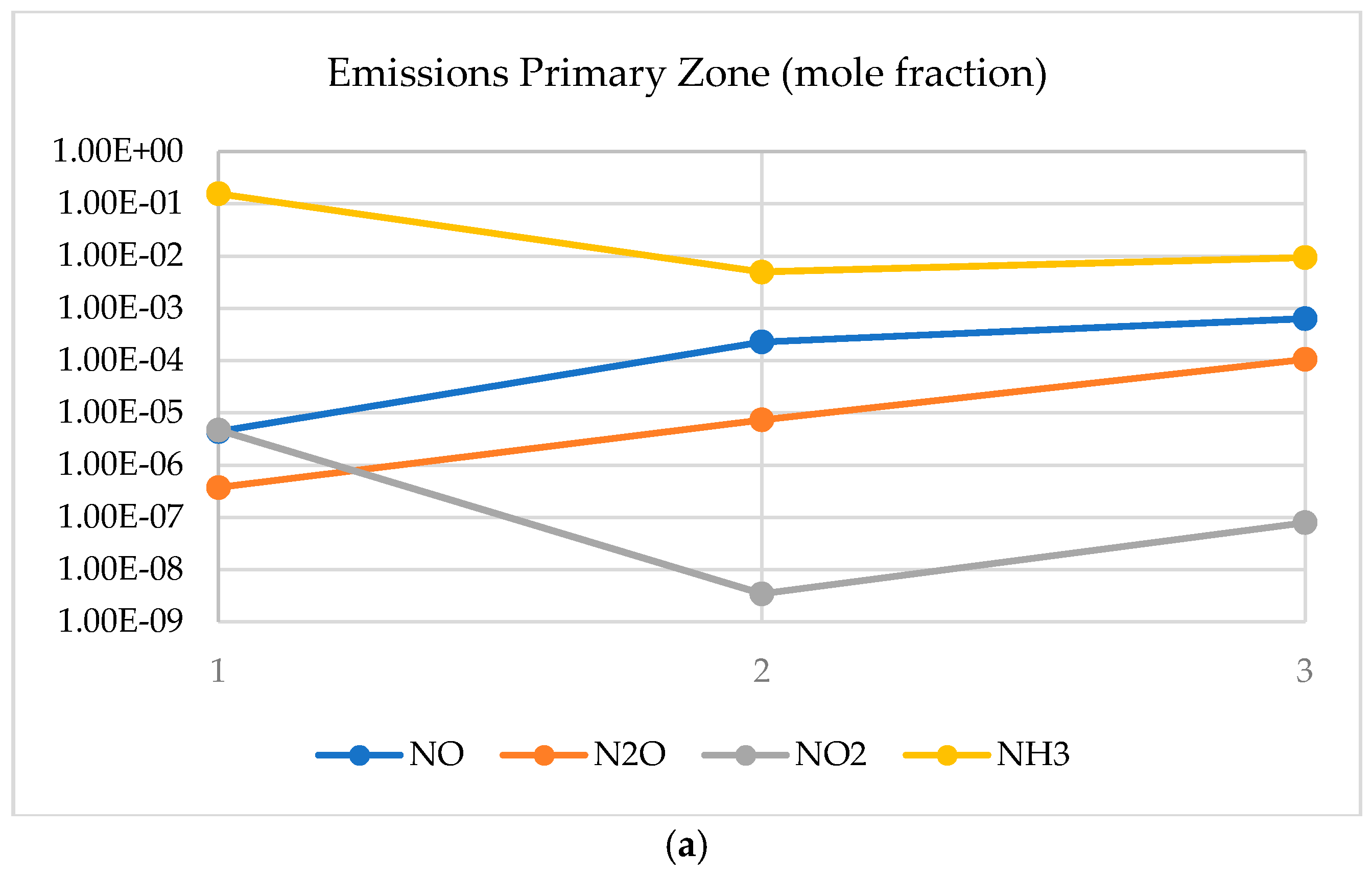
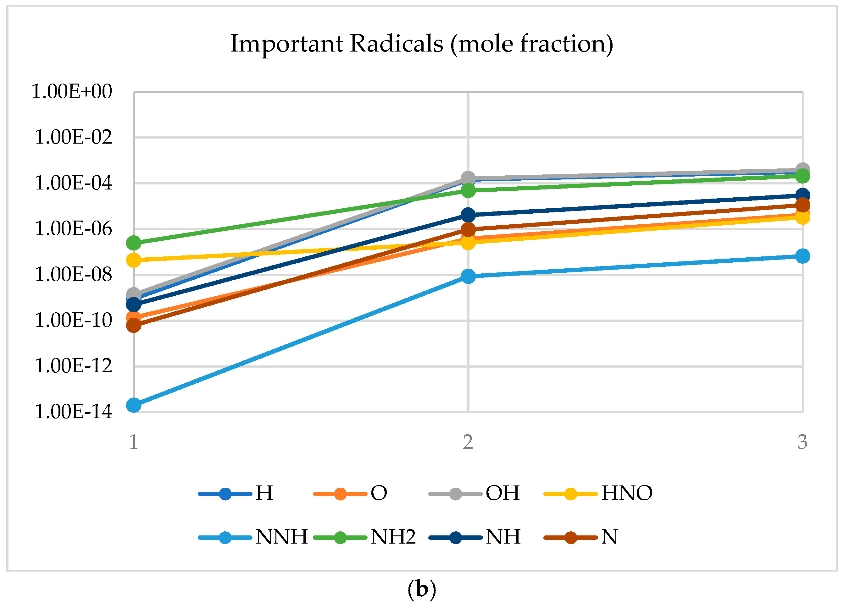
Results using the CRN showed the increase in nitrogen-based emissions at the primary zone. This behaviour was expected, as observed by others in similar experimental campaigns [5,6]. Increase in emissions is directly linked to the reduction of ammonia in the combustion area (Figure 3), which shows how the molecule has been considerably consumed across the flame with special emphasis in the central recirculation zone (i.e., since residence time in this region is greater than in the rest of the field, the presence of ammonia and its further recirculation enhance its reaction with species such as OH, a specie well-known to decompose NH3).
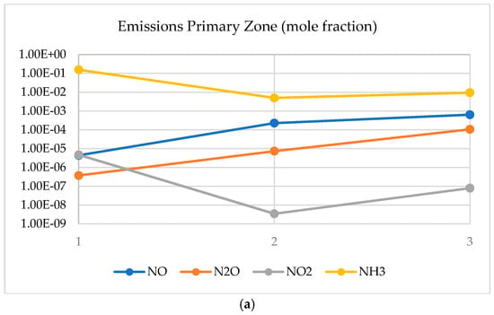
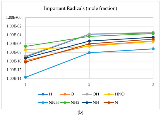
Figure 3.
Emissions (a) and radicals (b) in the primary combustion zone. 1. Mixing; 2. CRZ; 3. shearing flow.
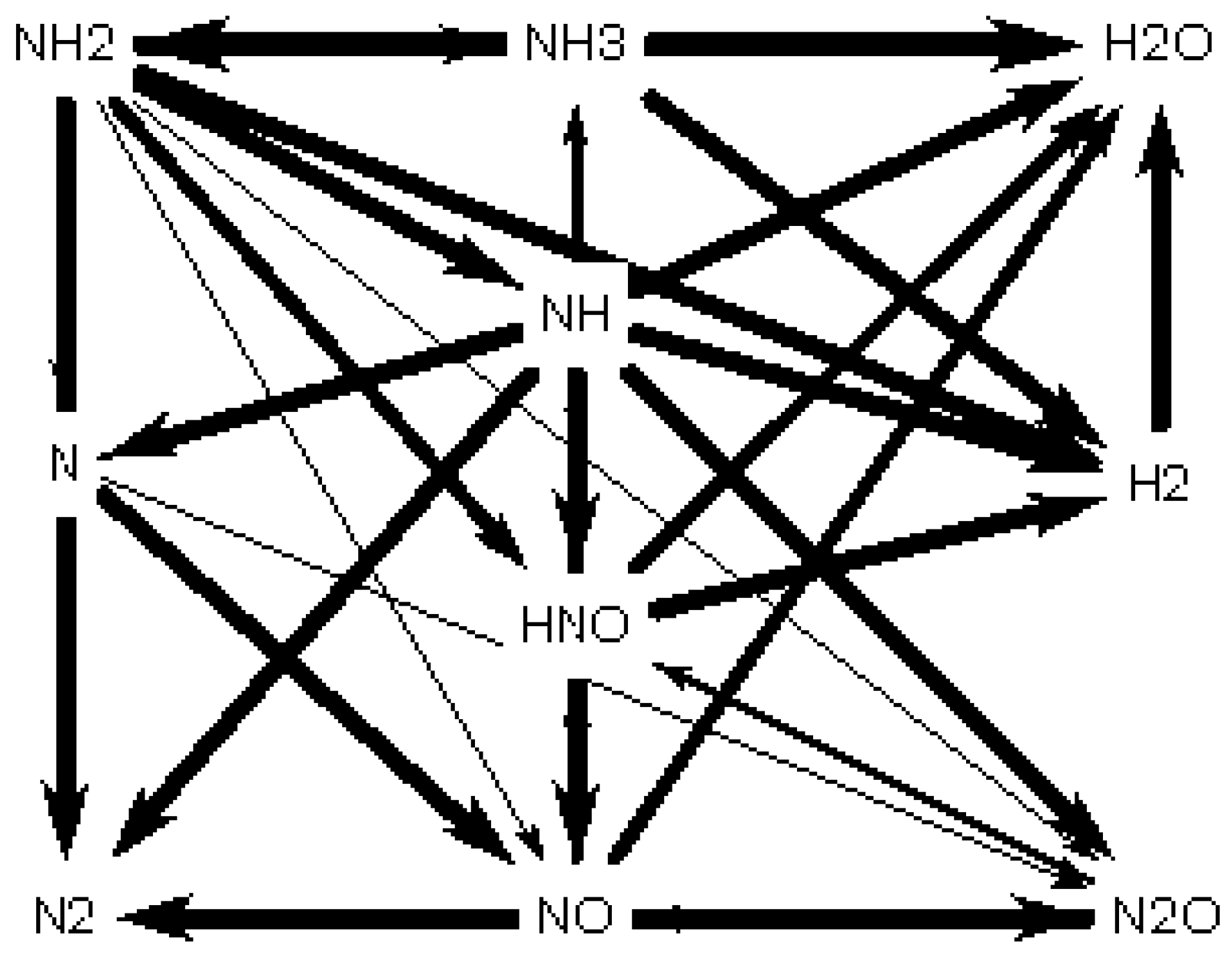
However, a pattern that has not been deeply investigated is how the production of radicals in the central recirculation zone plays an important role in the decomposition of ammonia whilst increasing nitrogen oxides. Figure 3 also denotes a considerable peak of radicals such as H, O and OH, all known to interact with NH and N to form HNO, precursor of NO, Figure 4. However, it also must be noted that all these radicals have not been consumed and most of them peak their concentration at the end of the combustion zone. The effect will lead to further recombination of species downstream the burner, in the post combustion zone. Another point to notice is that water has reached 39.9% molar fraction, whilst nitrogen and hydrogen have reached 54.9% and 4.4%, respectively (i.e., 99.2% of clean products).
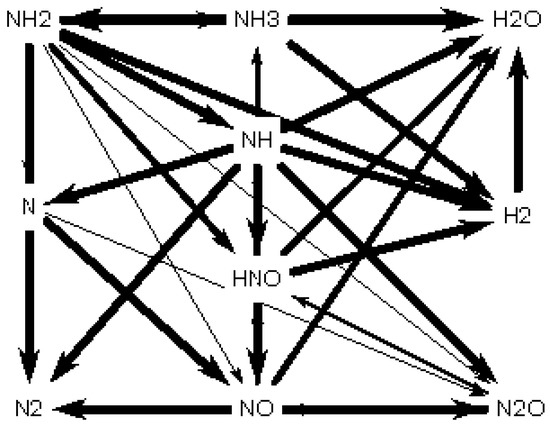
Figure 4.
Path of NO formation in the primary combustion zone. Reprinted with permission, Elsevier, 2020 [5].
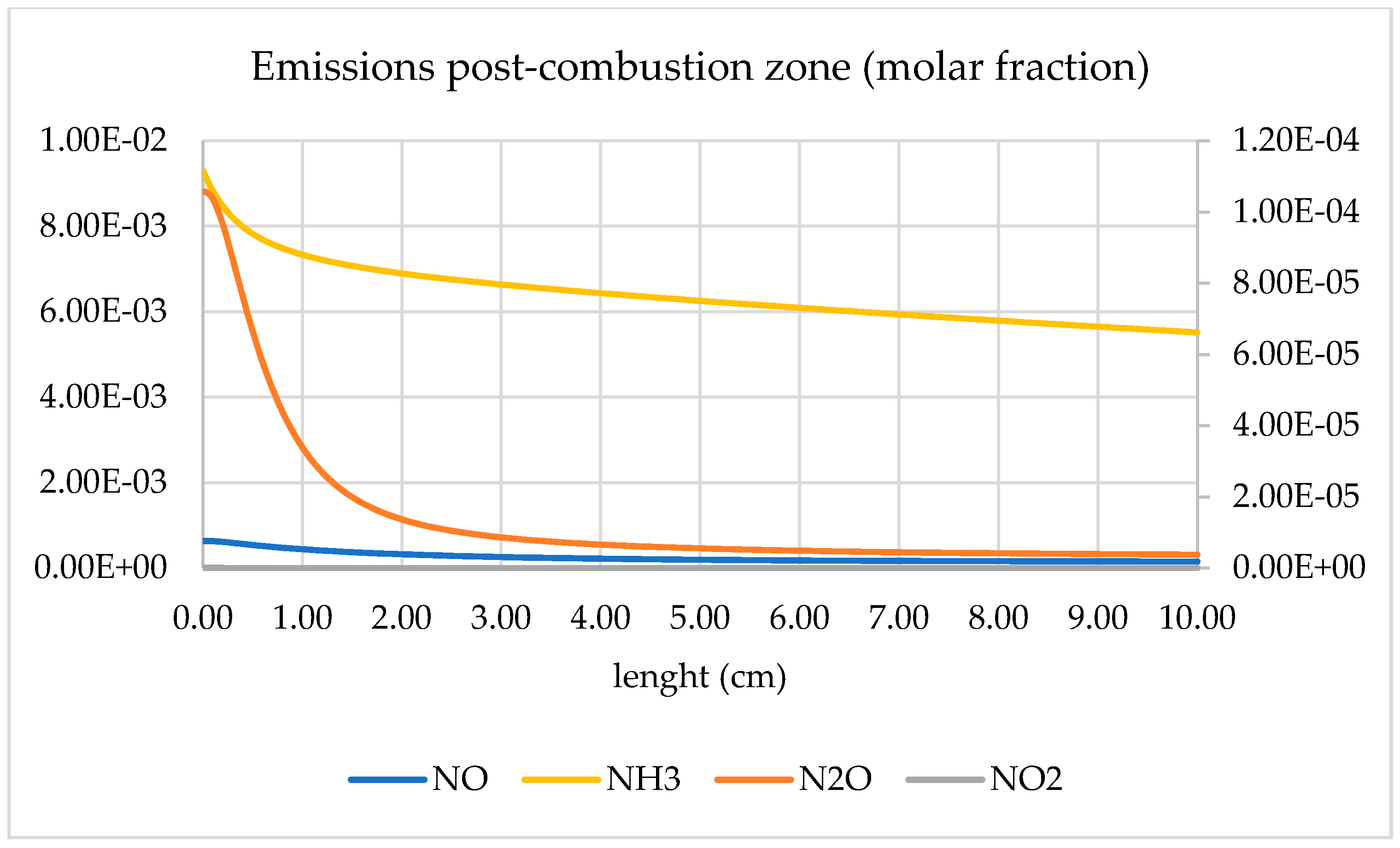
Further downstream, Figure 5, all these residual radicals keep reacting at high temperatures (~2031 K), directly impacting on the consumption of ammonia and mitigation of nitrogen oxides. Of particular interest is the high reaction of N2O, which at the high temperatures and elevated radical concentration keeps reacting to produce N2 or NO (which has barely suffered any major recombination compared to N2O). Thus, by the end of the combustion chamber, the emissions from the system are mainly comprised by clean species (N2, H2O and H2) with traces of unburned ammonia (0.6% molar fraction) and minimal traces of nitrogen oxides (below 10 ppm). A method that can be used to minimise both emissions, i.e., ammonia and NOx, could be the recirculation of these species in a post-treatment chamber, since ammonia is used as a de-NOxing agent for other applications (automotive, power plants, etc.). However, that point is left for further research out of the scope of this work.
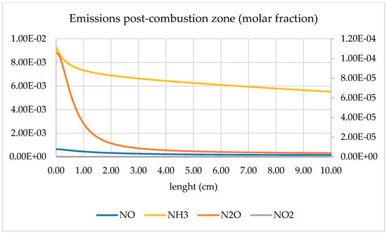
Figure 5.
Emissions in post combustion zone.
3.2. Numerical Analyses—Gas Turbine Cycle
The combustion chamber balance was determined and with it the mass balance of the entire gas turbine cycle. Mass flows, cycle performance and thermodynamic parameters for the new ammonia/hydrogen cycle were defined according to best combustion performance done by CHEMKIN-PRO, Table 1. Steam for the cycle is prepared separately, although its preparation can be integrated in the system, a point out of the scope of this manuscript.

Table 1.
Inlet parameters values for basic humidified Brayton cycle.
Initial results produced a total plant efficiency of 34%. This efficiency value is the first obtained during initial simulations using ammonia/hydrogen. Thus, it was used as the benchmark value to improve using the new parameters. Other values were determined as follow: efficiency 34%, power outlet 3.56 MW, heat rate 10.57 MJ/kWh, outlet temperature 827.56 K, and fuel added 10.45 WM.
3.3. Inlet Parameters Range Determination
These initial values were taken as references for a benchmark humidified Brayton. The benchmark value is defined by the red line in the following graphs, Figure 2, Figure 3, Figure 4, Figure 5, Figure 6, Figure 7, Figure 8 and Figure 9.

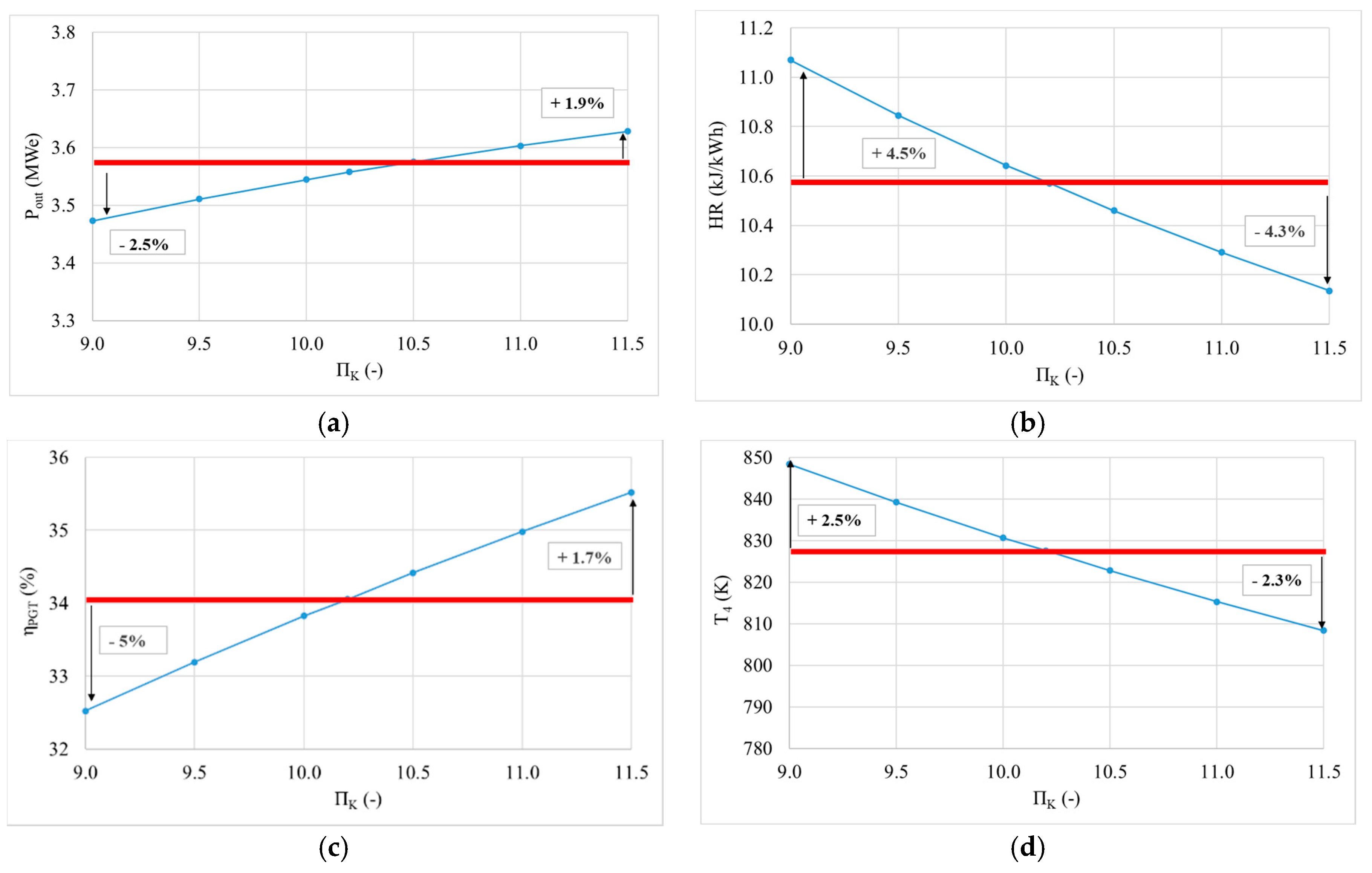
Figure 6.
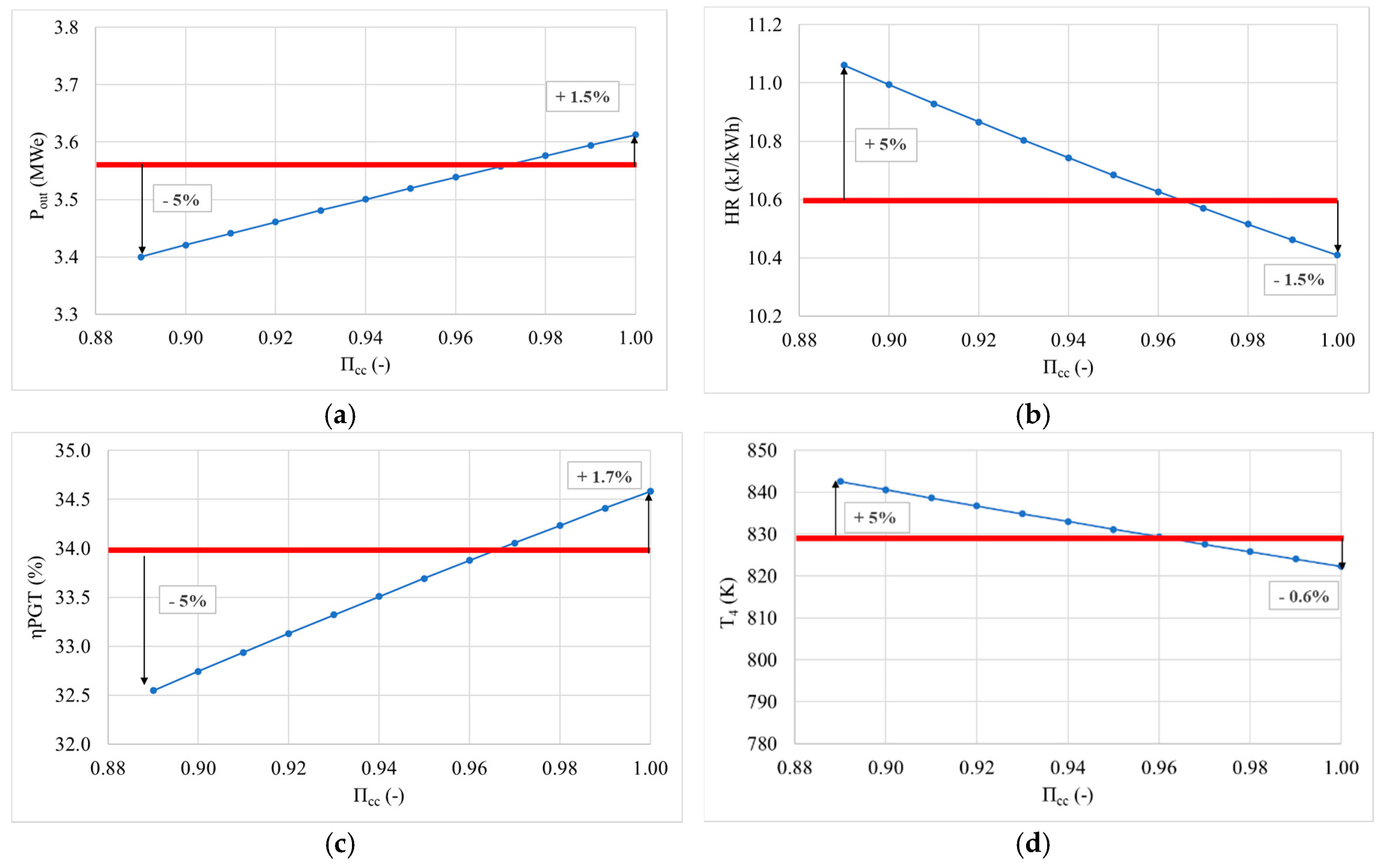
Change of gas turbine cycle outlet parameters in function of compressor pressure ratio (a) power change in function of compressor pressure ratio, (b) heat rate change in function of compressor pressure ratio, (c) gas turbine plant efficiency change in function of compressor pressure ratio and (d) change of temperature of the expanded products at the gas turbine outlet in function of compressor pressure ratio.
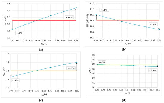
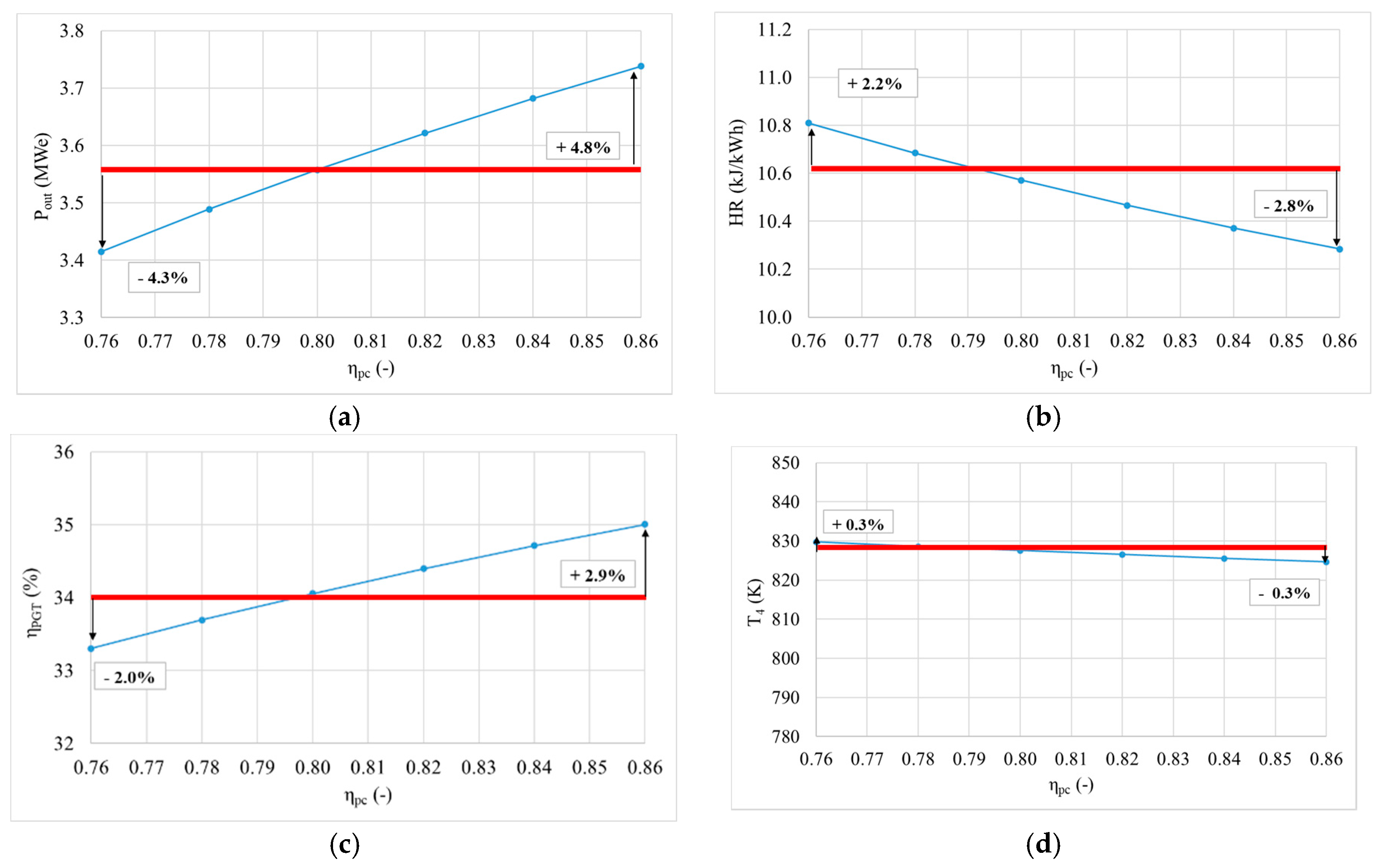
Figure 7.
Change of gas turbine cycle outlet parameters in function of compressor polytropic efficiency (a) power change in function of compressor polytropic efficiency, (b) heat rate change in function of compressor polytropic efficiency, (c) gas turbine plant efficiency change in function of compressor polytropic efficiency and (d) change of temperature of the expanded products at the gas turbine outlet in function of compressor polytropic efficiency.
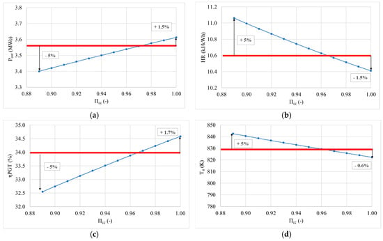
Figure 8.
Change of gas turbine cycle outlet parameters in function of combustion chamber pressure ratio (a) power change in function of combustion chamber pressure ratio, (b) heat rate change in function of combustion chamber pressure ratio, (c) gas turbine plant efficiency change in function of combustion chamber pressure ratio and (d) change of temperature of the expanded products at the gas turbine outlet in function of combustion chamber pressure ratio.

Figure 9.
Change of gas turbine cycle outlet parameters in function of combustion chamber efficiency (a) gas turbine plant efficiency change in function of combustion chamber efficiency and (b) heat rate change of the expanded products at the gas turbine outlet in function of combustion chamber efficiency.
3.3.1. Compressor Pressure Ratio
The compressor pressure ratio was analysed in a range from 8.5 to 12. Figure 6 shows how these changes affect power, heat rate, gas turbine plant efficiency and temperature of the expanded combustion products at the outlet of the gas turbine. It is clear that higher compression ratio will positively impact on power output and efficiency at the cost of lower heat rate and temperature at the outlet. However, lower values than the reference impact the following parameters, (a) useful work (Equation (1)), which affects power and heat rate, (b) facility efficiency (Equation (6)), and (c) temperature of combustion products at the gas turbine outlet (Equation (5)). As shown in Figure 2, the increase of compressor ratio to 11.5 could increase power by 1.9% and efficiency by 1.7%, while decrease to 8.5 would lower the power and efficiency for ~5%, which was the criterion of the present analysis. On the other hand, with values of the compressor ratio higher than 10.2, heat rate and outlet temperature decrease by 4.3% and 2.3% respectively, while with lower values than 10.2 both increase, heat rate by 4.5% and outlet temperature by 2.5%.
3.3.2. Compressor Polytropic Efficiency
The compressor polytropic efficiency was analysed in a range from 76% to 86%. The impact of this parameter is reflected in the compressor useful work (Equation (1)) and the compressor outlet temperature (Equation (2)). These parameters affect power and efficiency, as well as combustion parameters. The compressor polytropic efficiency affects expansion and therefore outlet temperature. Figure 3 shows the change of outlet parameters—power, heat rate, gas turbine plant efficiency and temperature of the combustion products at the gas turbine outlet. Variations were less than 5% across all parameters, and similarly to the compression ratio, both efficiencies and power increase with higher polytropic efficiencies, by 2.9% and 4.8%, respectively, while heat rate and outlet power decrease by 2.8% and 0.3%, respectively. Figure 7 shows that compressor polytropic efficiency has almost insignificant impact on the outlet temperature, compared to the impact on the compressor ratio, Figure 2. On the other hand, with a compressor polytropic efficiency decrease, power and efficiency decrease by 4.3% and 2.0%, respectively, while heat rate increases by 2.2%. The outlet temperature increase is almost insignificant by ~0.3%. The efficiency increase can go up to 2.9% using polytropic efficiencies of 86%, value close to new units.
3.3.3. Combustion Chamber Pressure Ratio
The combustion chamber pressure ratio was also analysed in a range from 85% to 100%. Figure 8 shows the changes of outlet parameters, as previously depicted. Interestingly, there is a high sensitivity from all parameters to the combustion chamber pressure ratio (i.e., an increase in 1% pressure ratio leads to 0.5% increase in power and 0.6% efficiency). This behaviour is related to the high dependency of the system to pressure changes, i.e., Figure 2, combined with more energy from the combustion chamber to produce power. The parameter will also impact on NOx emissions and the reduction of unburned ammonia emissions. However, these points are out of the scope of this work. The impact of the combustion chamber pressure ratio is reflected in expansion useful work (Equation (5)) and therefore in efficiency and power calculations. The increase of the combustion chamber pressure ratio above the referent value of 0.97 to 1.00, increases the power and efficiency by ~1.5%, while heat rate decreases by 1.5% and outlet temperature by 0.6%. The decrease of the combustion chamber pressure ratio below the referent value of 0.89 decreases the power and efficiency by ~5.0%, the lowest criterion, and increases heat rate and outlet temperature by 5.0%.
3.3.4. Combustion Chamber Efficiency
The combustion chamber efficiency was analysed in a range from 80% to 95%, Figure 9. Changes of turbine outlet temperature and power output are not presented since these changes are insignificant when changing the combustion chamber efficiency. An increase of the combustion chamber efficiency above the reference value of 0.90 to 0.94 will increase the overall efficiency up to 5%, while heat rate decreases by ~5.0%. Decrease of the combustion chamber efficiency below the reference value of 0.87 decreases the efficiency by ~3.8% and increases the heat rate by 3.8%. Higher combustion chamber efficiencies will positively impact on overall cycle efficiency at the cost of lower heat rate.
3.3.5. Steam/Fuel Ratio
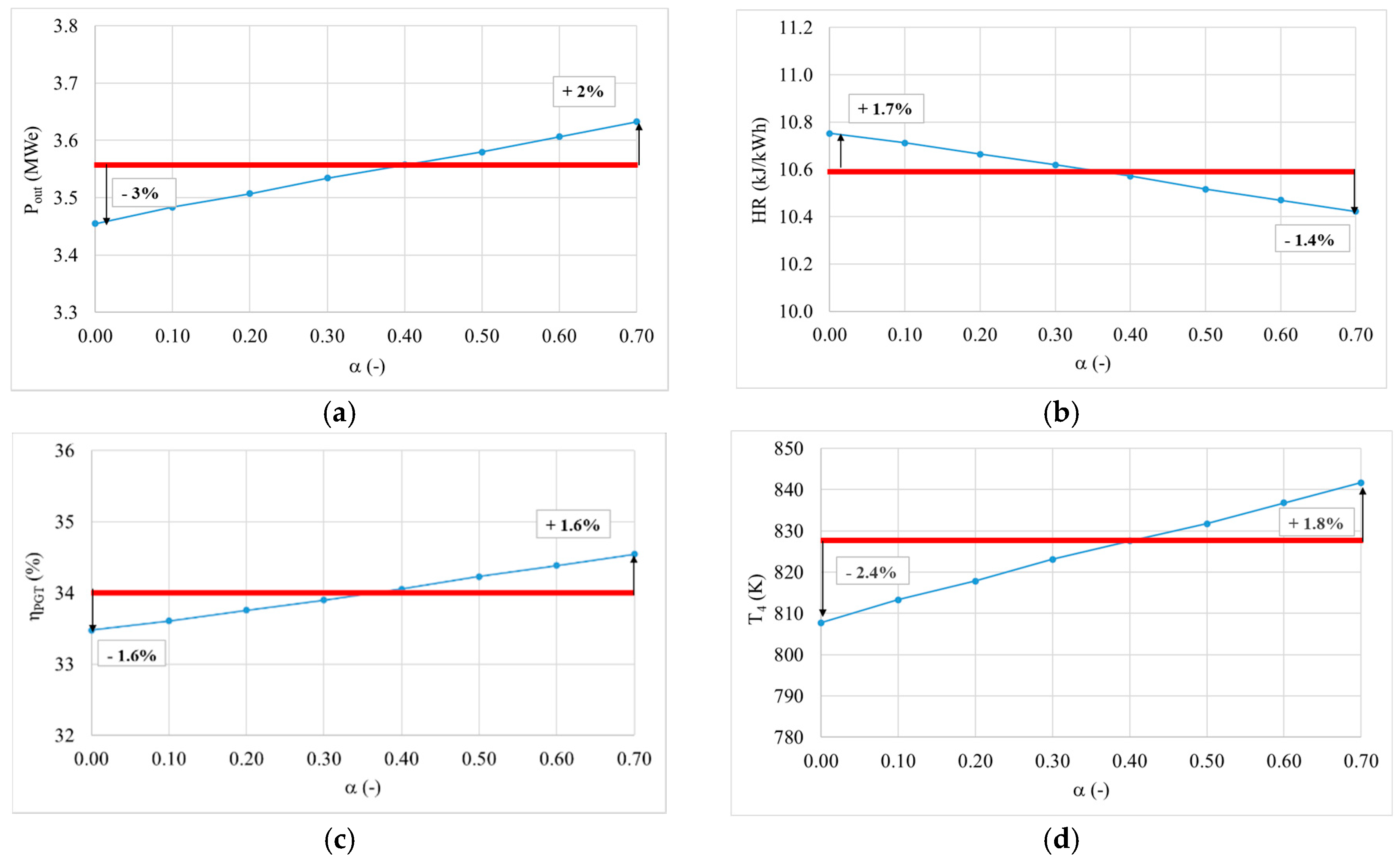
The steam/fuel ratio was analysed in a range from 0.0 to 0.7. The steam/fuel ratio is calculated as the mass flow of the steam to the mass flow of the fuel at the combustion chamber inlet. The upper limit value was set to 0.7 due to unstable conditions and low performance during combustion, leading eventually to blow off [5]. Impact of the steam/fuel ratio is analysed through combustion and expansion calculations, especially combustion chamber energy balances (Equation (4)), expansion useful work (Equation (3)), and expansion outlet temperature (Equation (5)), which all affect the gas turbine plant efficiency (Equation (6)). Figure 10 shows the sensitivity of the outlet parameters to this variable. Due to low steam ratios compared to the already vast amount of steam leaving the engine (>95% of the exhaust gases are nitrogen and water [5]), the parameter is not a major contributor to the increase of either efficiency or power (i.e., 10% increase in steam would only increase ~0.5% efficiency and 0.7% power). Moreover, it has been documented that further increase of steam can lead to a reduction in combustion efficiency, with higher emissions and lower combustion performance [5]. Therefore, this parameter does not seem to be critical to improve the power plant, instead works on these blends should be focused on improving the combustion patterns [41].
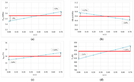
Figure 10.
Change of gas turbine cycle outlet parameters in function of steam/fuel ratio (a) power change in function of steam/fuel ratio, (b) heat rate change in function of steam/fuel ratio, (c) gas turbine plant efficiency change in function of steam/fuel ratio and (d) change of temperature of the expanded products at the gas turbine outlet in function of steam/fuel ratio.
3.3.6. Gas Turbine Polytropic Efficiency
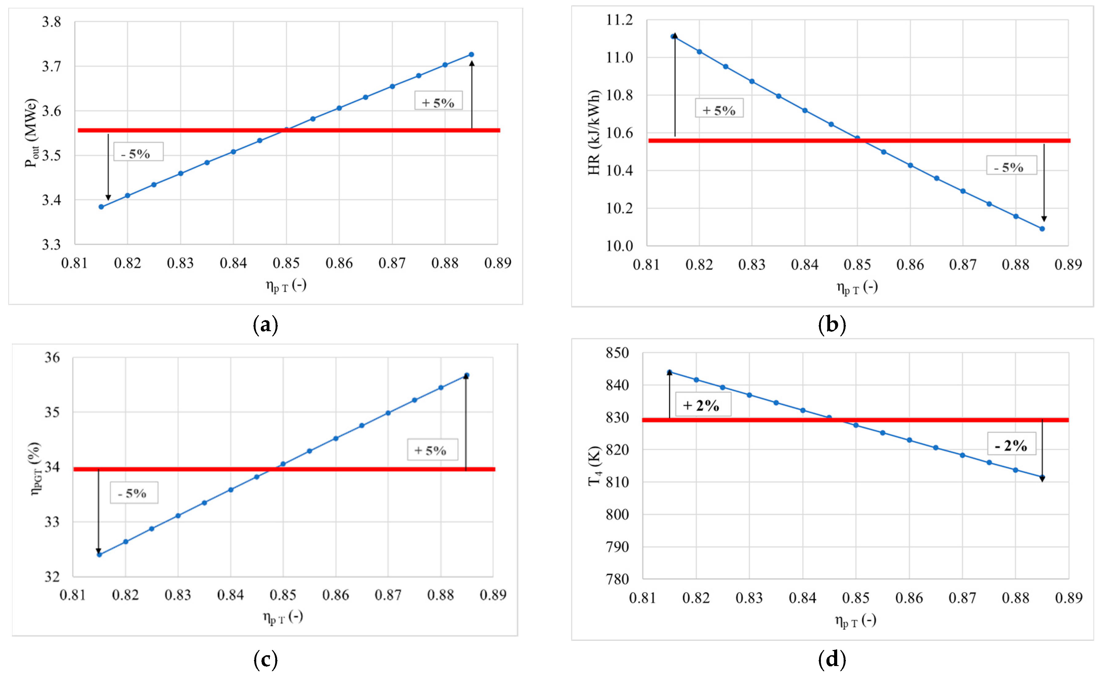
The gas turbine polytropic efficiency was analysed in a range from 80% to 90%, Figure 11. Gas turbine polytropic efficiency affects the gas turbine useful work (Equation (3)) and therefore outlet temperature of the combustion products (Equation (5)) and overall efficiency (Equation (6)). The gas turbine polytropic efficiency increases from the reference value of 85% up to 90%, resulting in an output power increase up to 3.73 MWe compared to the benchmark value of 3.56 MWe. Efficiencies also increase up to 36% compared to benchmark value of 34%. Increase of the power and efficiency is achieved by ~5.0%, while heat rate decreased to the lowest criterion value (5%) with outlet temperature decreasing by ~2.0%. With lower values of gas turbine polytropic efficiency due to gas turbine construction limitations, power and efficiency decrease by ~5.0% to 0.815, while heat rate increases by ~5.0% and outlet temperature by ~2.0%. An increase of output power and overall efficiency is followed by a decrease of heat rate and outlet temperature.
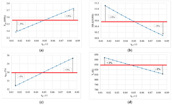
Figure 11.
Change of gas turbine cycle outlet parameters in function of turbine polytropic efficiency (a) power change in function of turbine polytropic efficiency, (b) heat rate change in function of turbine polytropic efficiency, (c) gas turbine plant efficiency change in function of turbine polytropic efficiency and (d) change of temperature of the expanded products at the gas turbine outlet in function of turbine polytropic efficiency.
3.3.7. Mechanical Efficiency
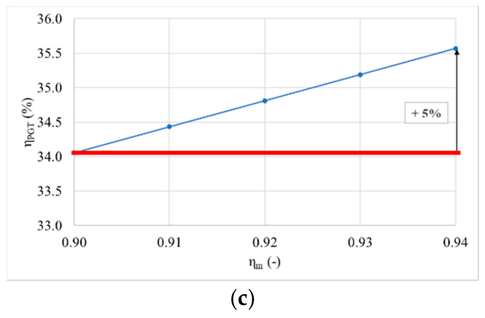
Mechanical losses were also included in the study in a range from 90% [45,46] to 94%, Figure 12. As observed, mechanical efficiencies are a paramount parameter to increase efficiency and power. This assertion is intuitive, as it is clear that better engines with fewer losses can deliver more power outputs recovering higher energies from the gaseous streams, providing better benefits. Therefore, it must be emphasized that gas turbine systems running on ammonia need to have high reliability, not only to reduce maintenance costs but also to keep efficiencies high enough to compete with fossil technologies. This is a challenge per se, as the production of water from ammonia engines comes with the production of alkaline and acidic exhaust streams, posing a new obstacle for the development of materials capable of withstanding these complex atmospheres at high temperatures above 1900 K [5].

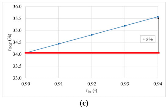
Figure 12.
Change of gas turbine cycle outlet parameters in function of mechanical efficiency (a) power change in function of mechanical efficiency, (b) heat rate change in function of mechanical efficiency and (c) gas turbine plant efficiency change in function of mechanical efficiency.
3.3.8. Cooling Air Ratio
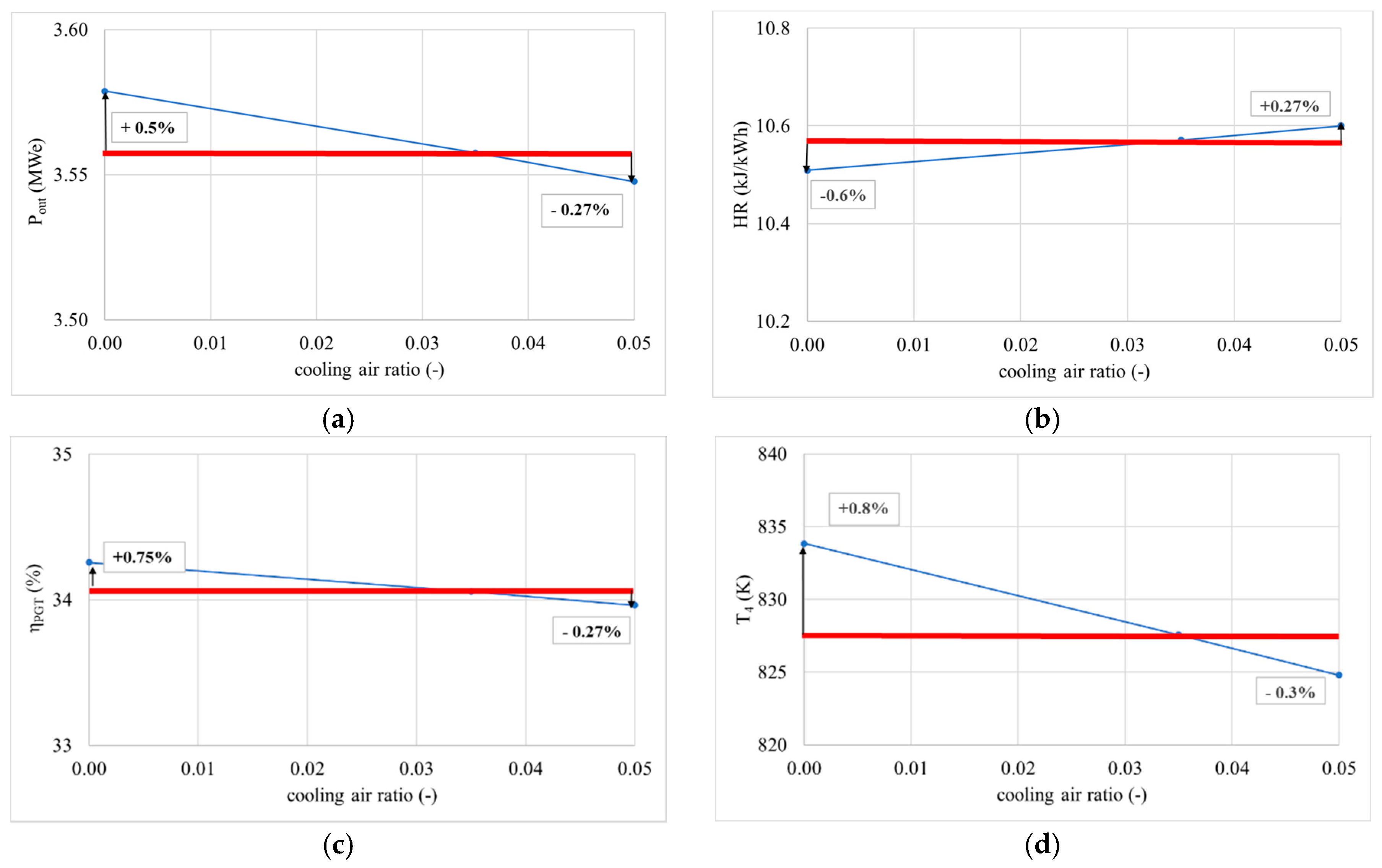
The cooling air ratio was also studied in a range from 0.00 to 0.05. The cooling air ratio is defined as the cooling air mass flow to the air mass flow at the compressor inlet. Figure 13 shows the changes of the outlet parameters based on this variable. The selected mathematical method [5], which is used as theoretical base for development of the gas turbine simulation model, considers continuous distribution of cooling air through expansion. This approach represents an ideal case for cooling air expansion. Since the distribution of the cooling air for the analysed gas turbine plant is not continuous, it is necessary to consider the impact of the discontinuous distribution of air. In the gas turbine plant, which was adopted as a reference for the purposes of a mathematical modelling and benchmark value of cooling air ratio, 2.5% of the overall air mass flowing through the compressor is introduced into the stationary vane whilst 1% is injected into moving vanes of the first turbine stage. The impact of the cooling air ratio variation to the outlet parameters is a decrease of less than 1% in both outlet power and overall efficiency in a range that goes from no cooling (0.00) to the benchmark value of 3.5% (0.035). Stronger impacts are noticeable with further increase of the cooling air mass flow above 3.5%, with a decrease of the outlet power and overall efficiency up to 0.3% using cooling air mass flow values of 5%.
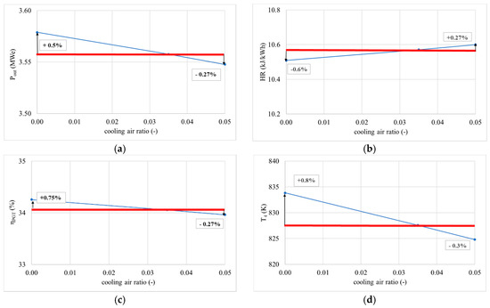
Figure 13.
Change of gas turbine cycle outlet parameters in function of cooling air ratio (a) power change in function of cooling air ratio, (b) heat rate change in function of cooling air ratio, (c) gas turbine plant efficiency change in function of cooling air ratio and (d) change of temperature of the expanded products at the gas turbine outlet in function of cooling air ratio.
Table 2 presents a summary of the all above presented results.
3.4. Super-Efficient Gas Turbine Ammonia/Hydrogen Cycle
The best values for all parameters were employed to determine the maximum efficiency value for the humidified ammonia/hydrogen cycle. Table 3 presents the parameters employed for such calculations, thus delivering the highest efficiency possible with the analysed unit.

Table 3.
Inlet parameters values for superefficient basic humidified Brayton cycle.
Values of outlet parameters for this case were: efficiency 43.4%, power outlet 4.37 MW, heat rate 8.29 MJ/kWh, outlet temperature 792.40 K, the amount of fuel added 10.45 WM.
It is clear that the efficiency of the unit can be increased considerably in almost 10%, with much higher power outputs and lower temperature outlets. It is also noticeable that the parameters employed in the calculations are real and feasible in new gas turbine models, whilst the reduction of water in the combustion chamber will also impact on the formation of radicals to mitigate NOx emissions. Therefore, the high efficiency unit can accomplish large power whilst producing only water, nitrogen, hydrogen and small traces of ammonia. A point of interest is that the high water production in the combustion chamber (consequence of the recombination of NH3 with air) will lead to a highly humidified atmosphere for the expansion in the turbine, thus leading to the use of humidification at the injector only for chemical purposes (i.e., formation of larger pools of OH, O and H radicals for further recombination with NOx and ammonia in post combustion zones).
4. Conclusions
The current study focuses on the prediction of the combustion and emissions performance, and various outlet parameters and their sensitivity to other inlet parameters in a gas turbine cycle fuelled with humidified ammonia/hydrogen blends.
The results denote the following,
- High production of NOx and reactivity of ammonia occur at the central recirculation zone of the primary flame. However, the large pools of OH, H, O and N-based radicals are not entirely consumed in this region.
- Further recombination of these species with the already formed NOx and N2O species bring down the concentration of pollutant emissions at the end of the combustion chamber. An atmosphere comprised of 99.2% clean products (N2, H2O and H2) is obtained. However, it is clear that further use of ammonia (at 0.6% vol. concentration) can be accomplished using other post combustion techniques.
- The requirement of high-pressure ratios and low mechanical losses will increase power, thus making feasible the use of ammonia-based blends to produce power efficiently. Similarly, and as expected, the compressor polytropic efficiency and combustion efficiency also have a considerable impact on the final power output of the cycle.
- Also, it was observed that steam/fuel injection ratios were not critical for the improvement of efficiency or power, as the amount of steam is relatively small. Thus, further studies using humidified ammonia blends should focus on the chemistry and mitigation of NOx and emissions rather than the potential of this technique to raise efficiency or power outputs. Although the steam/fuel injection ratio is relatively low for conventional humidification purposes, the parameter produces limited impact to the process as a consequence of the high humidification increased caused by decomposition of ammonia (39.9% water concentration).
- Strong impacts were observed with an increase of the cooling air mass flow above 3.5%, with a decrease of the outlet power and overall efficiency up to 0.3% using cooling air mass flow values of 5%.
- Theoretical superefficient ammonia/hydrogen cycles could be obtained with the application of improved inlet parameters values (i.e., compressor, combustor, turbine and cooling), reaching theoretical maximum cycle efficiencies up to 43.4%. Thus, making highly competitive these cycles to fossil-based systems.
Author Contributions
Conceptualization, methodology, validation, software, acquisition and administration were performed by both authors, A.V.-M. and M.G.B.; funding acquisition, A.V.-M. All authors have read and agreed to the published version of the manuscript.
Funding
This research was funded by EPSRC, Stored Ammonia for Energy (SAFE)—AGT PILOT, project no. EP/T009314/1. Information on the data underpinning the results presented here, including how to access them, can be found in the Cardiff University data catalogue at 10.17035/d.2020.0120116779.
Conflicts of Interest
The authors declare no conflict of interest.
Nomenclature
| Ratio of the mass flowrate of the fuel and the air at the combustion chamber inlet (-) | T | temperature (K) | |
| cp CRN CRZ | Heat capacity at constant pressure (kJ/kgK) Chemical Reaction Network Central Recirculation Zone | To | the inlet compressor temperature (K) |
| is the combustion chamber inlet steam enthalpy (kJ/kg) | T2 | the outlet compressor temperature (K) | |
| is enthalpy of steam at the combustion chamber outlet (kJ/kg) | combustion products temperature at the turbine inlet (K) | ||
| hfuel | specific enthalpy of fuel at combustion chamber inlet (kJ/kg) | combustion products temperature at the end of the expansion (K) | |
| specific work of compression (kJ/kg) | the efficiency of a combustion chamber (-) | ||
| plant specific work (kJ/kg) | the efficiency of a plant (-) | ||
| LHV | the lower heating value (kJ/kg) | the mechanical efficiency (-) | |
| overall specific work of the expansion of the combustion products and cooling air mixture (kJ/kg) | is the polytropic efficiency of a compressor (-) | ||
| combustion products mass flow (kg/s) | is the polytropic efficiency of a turbine (-) | ||
| fuel mass flow at the combustion chamber inlet (kg/s) | the compressor pressure ratio (-) | ||
| air mass flow at the compressor inlet (kg/s) | is the cooling air distribution factor (-) | ||
| air mass flow at the combustion chamber inlet (kg/s) | is the amount of the amount of fuel added (kJ/kg) | ||
| is the cooling air distribution factor (-) | α | is the ratio of the vapour mass flow and fuel mass flow at the combustion chamber inlet (-) | |
| p PSR PFR | pressure (Pa) Perfectly Stirred Reactor Plug Flow Reactor | air mass flow for sealing relative to air mass flow at the compressor inlet (-) | |
| R | the universal gas constant (J/(mol.K)) | average relative error (%) | |
| cooling air mass flow specified to compressor inlet mass flow (-) |
References
- Birol, F. Hydrogen: Accelerating and Expanding Deployment; IEA: Paris, France, 2018. [Google Scholar]
- Posada, J.O.G.; Abdalla, A.H.; Oseghale, C.I.; Hall, P.J. Multiple regression analysis in the development of NiFe cells as energy storage solutions for intermittent power sources such as wind or solar. Int. J. Hydrog. Energy 2016, 41, 16330–16337. [Google Scholar] [CrossRef]
- Bowermaster, D. Renewable Ammonia Generation, Transport, and Utilization in the Transportation Sector; Technical Report for Electric Power Research Institute (EPRI): Palo Alto, CA, USA, February 2019. [Google Scholar]
- Kobayashi, H.; Hayakawa, A.; Somarathne, K.D.K.A.; Okafor, E.C. Science and Technology of Ammonia Combustion. Proc. Combust. Inst. 2018, 37, 109–133. [Google Scholar] [CrossRef]
- Guteša Božo, M.; Vigueras-Zuniga, M.O.; Buffi, M.; Seljak, T.; Valera-Medina, A. Fuel Rich Ammonia/Hydrogen Injection for Humidified Gas Turbines. Appl. Energy 2019, 251, 113334–1133346. [Google Scholar] [CrossRef]
- Valera-Medina, A.; Guteša, M.; Xiao, H.; Pugh, D.; Giles, A.; Goktepe, B.; Marsh, R.; Bowen, P. Premixed Ammonia/Hydrogen Swirl Combustion under Rich Fuel Conditions for Gas Turbines Operation. Int. J. Hydrog. Energy 2019, 44, 8615–8626. [Google Scholar] [CrossRef]
- Valera-Medina, A.; Syred, N.; Griffiths, A. Visualization of Isothermal Large Coherent Structures in a Swirl Burner. Combust. Flame 2009, 156, 1723–1734. [Google Scholar] [CrossRef]
- Kurata, O.; Iki, N.; Matsunuma, T.; Inoue, T.; Tsujimura, T.; Furutani, H.; Kobayashi, H.; Hayakawa, A. Performances and emission characteristics of NH3–air and NH3-CH4–air combustion gas-turbine power generations. Proc. Combust. Inst. 2017, 36, 3351–3359. [Google Scholar] [CrossRef]
- Hayakawa, A.; Goto, T.; Mimoto, R.; Arakawa, Y.; Kudo, T.; Kobayashi, H. Laminar burning velocity and Markstein length of ammonia/air premixed flames at various pressures. Fuel 2015, 159, 98–106. [Google Scholar] [CrossRef]
- Somarathne, K.D.K.A.; Hatakeyama, S.; Hayakawa, A.; Kobayashi, H. Numerical study of a low emission gas turbine like combustor for turbulent ammonia/air pre- mixed swirl flames with a secondary air injection at high pressure. Int. J. Hydrog. Energy 2017, 42, 27388–27399. [Google Scholar] [CrossRef]
- Xiao, H.; Howard, M.; Valera-Medina, A.; Dooley, S.; Bowen, P.J. Study on Reduced chemical mechanisms of ammonia/methane combustion under gas turbine conditions. Energy Fuels 2016, 30, 8701–8710. [Google Scholar] [CrossRef]
- Valera-Medina, A.; Marsh, R.; Runyon, J.; Pugh, D.; Beasley, P.; Hughes, T.; Bowen, P. Ammonia–methane combustion in tangential swirl burners for gas turbine power generation. Appl. Energy 2017, 185, 1362–1371. [Google Scholar] [CrossRef]
- Xiao, H.; Valera-Medina, A.; Marsh, R.; Bowen, P. Numerical study assessing various ammonia/methane reaction models for use under gas turbine conditions. Fuel 2017, 196, 344–351. [Google Scholar] [CrossRef]
- Valera-Medina, A.; Morris, S.; Runyon, J.; Pugh, D.; Marsh, R.; Beasley, P.; Hughes, T. Ammonia, methane and hydrogen for gas turbines. Energy Procedia 2015, 75, 118–123. [Google Scholar] [CrossRef]
- Valera-Medina, A.; Pugh, D.G.; Marsh, P.; Bulat, G.; Bowen, P. Preliminary study on lean premixed combustion of ammonia-hydrogen for swirling gas turbine combustors. Int. J. Hydrog. Energy 2017, 42, 24495–24503. [Google Scholar] [CrossRef]
- Xiao, H.; Valera-Medina, A. Chemical kinetic mechanism study on premixed combustion of ammonia/hydrogen fuels for gas turbine use. J. Eng. Gas Turbines Power 2017, 139, 8. [Google Scholar] [CrossRef]
- Chiesa, P. Combined Cycle Systems for Near-Zero Emission Power Generation, Chapter 5: Novel Cycles: Humid Air Cycle Systems; Woodhead Publishing (Elsevier): Cambridge, UK, 2012; pp. 162–185. [Google Scholar]
- Jonsson, M.; Yan, J. Humidified gas turbines—A review of proposed and implemented cycles. Energy 2005, 30, 1013–1078. [Google Scholar] [CrossRef]
- Taimoor, A.A.; Muhammad, A.; Saleem, W.; Zain-ul-Abdein, M. Humidified exhaust recirculation for efficient combined cycle gas turbines. Energy 2016, 106, 356–366. [Google Scholar] [CrossRef]
- Shaposhnikov, V.V.; Biryukov, B.V. On the Efficiency of Heat and Electric Power Plants Based on Combined-Cycle Plants with Overexpansion of the Working Fluid in the Gas Turbine and Injection of Steam into the Gas Path. Chem. Pet. Eng. 2018, 54, 94–99. [Google Scholar] [CrossRef]
- De Paepe, W.; Carrero, M.M.; Bram, S.; Parente, A.; Contino, F. Toward higher micro gas turbine efficiency and flexibility-humidified micro gas turbines: A review. J. Eng. Gas Turbines Power 2018, 140, 4038365. [Google Scholar] [CrossRef]
- Carapellucci, R.; Giordano, L. Upgrading existing gas-steam combined cycle power plants through steam injection and methane steam reforming. Energy 2019, 173, 229–243. [Google Scholar] [CrossRef]
- Fallah, M.; Siyahi, H.; Ghiasi, R.A.; Mahmoudi, S.M.S.; Yari, M.; Rosen, M.A. Comparison of different gas turbine cycles and advanced exergy analysis of the most effective. Energy 2016, 116, 701–715. [Google Scholar] [CrossRef]
- De Paepe, W.; Renzi, M.; Carrerro, M.M.; Caligiuri, C.; Contino, F. Micro gas turbine cycle humidification for increased flexibility: Numerical and experimental validation of different steam injection models. J. Eng. Gas Turbines Power 2019, 141, 021009. [Google Scholar] [CrossRef]
- Xi, D.; Wang, Y.; Liu, J.-Z.; Zhou, J.-H. Current status in the study of the humidified combustion. J. Eng. Therm. Energy Power 2014, 29, 1–6. [Google Scholar]
- Huang, Z.; Yang, C.; Yang, H.; Ma, X. Off-design heating/power flexibility for steam injected gas turbine based CCHP considering variable geometry operation. Energy 2018, 165, 1048–1060. [Google Scholar] [CrossRef]
- Zhang, C.; Wang, X.; Yang, C.; Yang, Z. Control Strategies of Steam-injected Gas Turbine in CCHP System. Energy Procedia 2017, 105, 1520–1525. [Google Scholar] [CrossRef]
- De Paepe, W.; Sayad, P.; Bram, S.; Klingmann, J.; Contino, F. Experimental Investigation of the Effect of Steam Dilution on the Combustion of Methane for Humidified Micro Gas Turbine Applications. Combust. Sci. Technol. 2016, 188, 1199–1219. [Google Scholar] [CrossRef]
- De Paepe, W.; Carrerro, M.M.; Bram, S.; Parente, A.; Contino, F. Advanced Humidified Gas Turbine Cycle Concepts Applied to Micro Gas Turbine Applications for Optimal Waste Heat Recovery. Energy Procedia 2017, 105, 1712–1718. [Google Scholar] [CrossRef]
- De Paepe, W.; Montero Carrero, M.; Bram, S.; Contino, F.; Parente, A. Waste heat recovery optimization in micro gas turbine applications using advanced humidified gas turbine cycle concepts. Appl. Energy 2017, 207, 218–229. [Google Scholar] [CrossRef]
- Shahpouri, S.; Houshfar, E. Nitrogen oxides reduction and performance enhancement of combustor with direct water injection and humidification of inlet air. Clean Technol. Environ. Policy 2019, 21, 667–683. [Google Scholar] [CrossRef]
- Göke, S.; Paschereit, C.O. Influence of steam dilution on NOx formation in premixed natural gas and hydrogen flames. In Proceedings of the 50th AIAA Aerospace Sciences Meeting Including the New Horizons Forum and Aerospace Exposition 2012, Article number AIAA 2012-1272, 50th AIAA Aerospace Sciences Meeting Including the New Horizons Forum and Aerospace Exposition, Nashville, TN, USA, 9–12 January 2012. [Google Scholar]
- Best, T.; Finney, K.N.; Ingham, D.B.; Pourkashanian, M. CO2-enhanced and humidified operation of a micro-gas turbine for carbon capture. J. Clean. Prod. 2018, 176, 370–381. [Google Scholar] [CrossRef]
- Shukla, A.K.; Singh, O. Performance evaluation of steam injected gas turbine-based power plant with inlet evaporative cooling. Appl. Therm. Eng. 2016, 102, 454–464. [Google Scholar] [CrossRef]
- Guteša, M.; Al-Doboon, A.; Valera-Medina, A.; Syred, N.; Bowen, P. CARSOXY (CO2-Argon-Steam-OxyFuel) Combustion in Gas Turbines for CCS Systems. In Proceedings of the 55th AIAA Aerospace Sciences Meeting, Grapevine, TX, USA, 9–13 January 2017. [Google Scholar] [CrossRef]
- Al-Doboon, A.; Guteša, M.; Valera-Medina, A.; Syred, N.; Ng, J.-H.; Chong, C.T. CO2-argon-steam oxy-fuel (CARSOXY) combustion for CCS inert gas atmospheres in gas turbines. Appl. Therm. Eng. 2017, 122, 350–358. [Google Scholar] [CrossRef]
- Guteša Božo, M.; Valera–Medina, A.; Syred, N.; Bowen, P. Fuel quality impact analysis for practical implementation of corn COB gasification gas in conventional gas turbine power plants. Biomass Bioenergy 2019, 122, 221–230. [Google Scholar] [CrossRef]
- Valera-Medina, A. Ammonia Gas Turbines. ETN Annu. Gen. Meet. Work; European Turbine Network: Amsterdam, The Netherlands, 2020; p. 59. [Google Scholar]
- Valera-Medina, A.; Syred, N.; Bowen, P. Central recirculation zone visualization in confined swirl combustors for terrestrial energy. J. Propuls. Power 2012, 29, 195–204. [Google Scholar] [CrossRef]
- Pugh, D.; Runyon, J.; Bowen, P.; Giles, A.; Valera-Medina, A.; Marsh, R.; Goktepe, B.; Hewlett, S. An Investigation of Ammonia Primary Flame Combustor Concepts for Emissions Reduction with OH*, NH2* and NH*Chemiluminescence at Elevated Conditions. Proc. Combust. Inst. 2020. [Google Scholar] [CrossRef]
- Mathieu, O.; Petersen, E.L. Experimental and modelling study on the high-temperature oxidation of Ammonia and related NOx chemistry. Combust. Flame 2015, 162, 554–570. [Google Scholar] [CrossRef]
- Marsh, R.; Runyon, J.; Giles, A.; Morris, S.; Pugh, D.; Valera-Medina, A.; Bowen, P. Premixed methane oxycombustion in nitrogen and carbon dioxide atmospheres: Measurement of operating limits, flame location and emissions. Proc. Combust. Inst. 2016, 36, 3949–3958. [Google Scholar] [CrossRef]
- Müller, K.J. Thermische Strömungsmaschinen: Auslegung und Berechnung; Springer-Verlag: Vienna, Austria, 1978; pp. 1–2. [Google Scholar] [CrossRef]
- Guteša, M. The Numerical Simulation Model of Gas Turbine Facility for Biomass Gasification Gas Application. Ph.D. Thesis, Faculty of technical sciences, University of Novi Sad, Novi Sad, Serbia, 2017. (In Serbian). [Google Scholar]
- Pugh, D.G.; Bowen, P.; Valera-Medina, A.; Runyon, J. Influence of pressure and humidity on NOx formation in a staged premixed swirling NH3/H2 flame at conditions of elevated temperature and pressure. Proc. Comb. Inst. 2019, 37, 5401–5409. [Google Scholar] [CrossRef]
- Grković, V.; Guteša, M. Lessons in Thermal Energy Plants, Equipment and Devices, Technical Sciences Textbooks; Faculty of Technical Sciences: Novi Sad, Serbia, 2015; (In English and in Serbian). [Google Scholar]
Publisher’s Note: MDPI stays neutral with regard to jurisdictional claims in published maps and institutional affiliations. |
© 2020 by the authors. Licensee MDPI, Basel, Switzerland. This article is an open access article distributed under the terms and conditions of the Creative Commons Attribution (CC BY) license (http://creativecommons.org/licenses/by/4.0/).

