Article

Heat Transfer Performance of an Axially Rotating Heat Pipe for Cooling of Grinding

1
College of Mechanical and Electronic Engineering, Nanjing Forestry University, Nanjing 210037, China
2
College of Mechanical and Electrical Engineering, Nanjing University of Aeronautics and Astronautics, Nanjing 210016, China
*
Author to whom correspondence should be addressed.
Energies 2020, 13(21), 5745; https://doi.org/10.3390/en13215745
Submission received: 12 October 2020 / Revised: 27 October 2020 / Accepted: 31 October 2020 / Published: 2 November 2020
(This article belongs to the Section J: Thermal Management)

Abstract

:
Coolants are widely used to dissipate grinding heat in conventional grinding. This process, however, is not satisfactory as coolants often lose efficacy in grinding due to film boiling and can result in adverse health and environment effects. The present paper put forward the concept of a rotating heat pipe grinding wheel, attempting to reduce or eliminate the coolant amount and realize green machining. The heat transfer performance of rotating heat pipe grinding wheel was studied by using volume of fluid method in ANSYS/FLUENT. The influence of the input heat flux, filling ratio and rotational speed were investigated by a simulation method. Results show that the appropriate heat flux range for the rotating heat pipe grinding wheel was from 2000 to 100,000 W/m2, the ideal filling ratio was 50% and the rise of the rotational speed turned out to weaken the heat transfer coefficient. Finally, dry grinding experiments on Ti-6Al-4V were performed and the temperatures in both the rotating heat pipe and the grinding contact zone were monitored. The new designed rotating heat pipe grinding wheel showed a good prospect for application to green grinding of difficult-to-cut materials.

1. Introduction

Sustainable manufacturing is a specialized branch of sustainability, aiming towards the improvement of technological, environmental and economic aspects of manufacturing processes. Energy efficient, low waste generation, cost effectiveness, operational safety and operator’s health are the key features of sustainable manufacturing operation [1]. To follow sustainability criteria for manufacturing, efforts have been made to optimize the coolant types [2] and reduce the amount of coolant consumptions [3,4]. Gugulothu et al. [5] reported the cooling performance of vegetable oil-based fluid and machining performance turned out to be improved by the hybrid nano cutting fluid. Rabiei et al. [6] applied the minimum quantity lubricating (MQL) method in an ultrasonic-assisted grinding, shiny workpiece surface without any thermal damages were obtained. Sen et al. [7] took into account both the vegetable oil-based fluid and MQL in milling, and successfully reduced the tool wear by a maximum of about 19.35%. Despite the advantages, the extreme hydrodynamic pressure and severe machining temperature still limits the industrial application of MQL.
In addition to the abovementioned methods, rotating heat pipes [8,9,10] (RHP) have long been known as an effective cooling device that transfer heat by an internal phase change process. Application of rotating heat pipes has been attempted in the field of the spindle bearings, the drills and the other rotating occasions. Judd et al. [11] successfully reduced the bearing temperature by 50%, with an axially RHP embedded in the spindle. Jen et al. [12] successfully controlled the high drilling temperature in a deep-hole machining process by designing an axially RHP drill. In view of this, it is reasonable to apply the RHP in grinding to improve the heat transport efficiency in the grinding contact zone.
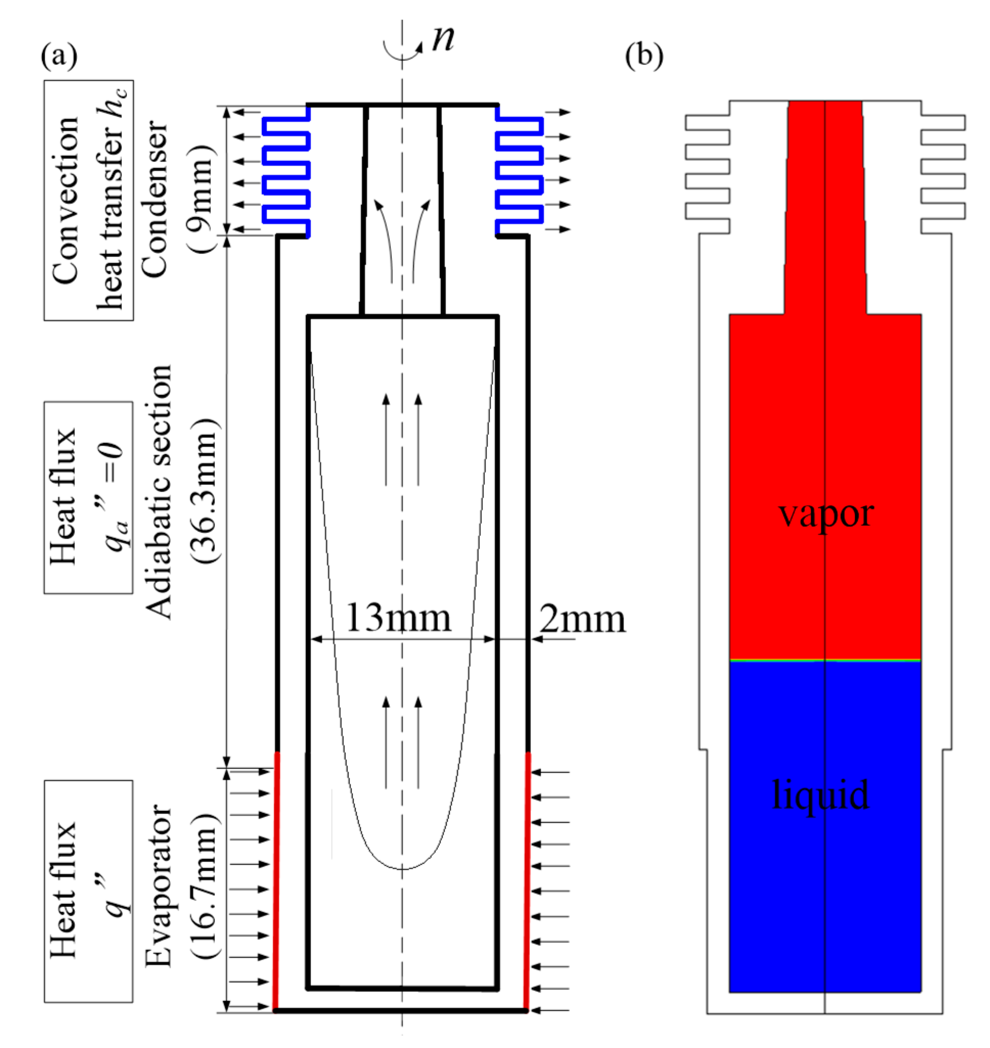
Therefore, in this paper, the effective heat transfer technology was applied in the grinding wheel matrix to realize green grinding. The concept of a rotating heat pipe grinding wheel (RHP-GW) was proposed and shown in Figure 1. In the RHP-GW, the grinding surface is the evaporator, and the cooled end with fins is the condenser. A taper with 2° is designed on the condenser inner wall. During grinding, the grinding heat is conducted to the working fluid, causing a phase change in the liquid. The vapor then moves to a condenser driven by the pressure gradient in the vapor zone. The vapor condenses in the condenser section due to an impinging jet cooling outside. The condensate flows to the evaporator due to the centrifugal force and the gravity, forming a thermodynamic cycle.
The object of this study is to analyse the heat transfer characteristics in the thermodynamic cycle by CFD modeling, which is now widely used in solving heat and mass transfer problems [13,14,15,16]. Factors such as input heat flux, filling ratio and rotational speed are investigated. Validation experiments are performed by dry grinding of Ti-6Al-4V. The temperature distribution in the RHP is monitored and compared with the simulation results. The grinding temperature in the contact zone and the workpiece quality are also tested to confirm the feasibility of the RHP for cooling of the grinding process.

2. Simulation Details

2.1. Simulation Model and Boundary Conditions

In this paper, the heat transfer characteristics in the RHP-GW was initially investigated using a simplified two-dimensional model (as shown in Figure 2) corresponding to its cross-section. The evaporator section was the grinding surface with grains, which has a length of 16.7 mm. The condenser was the finned section with a length of 9 mm. A taper of 2° was set inside the condenser section to promote the backflow. During grinding, the heat is generated in the contact zone and accumulates to a certain value, where the burn out usually happens suddenly. Therefore, constant heat flux was defined at the bottom of the evaporator section, by calculating the maximum heat flux according to the experimental results [17]. The condenser section was cooled by cold air, so a constant heat transfer coefficient of 716.4 W / ( m 2 · K ) was set outside the condenser section. Zero heat flux boundary conditions were defined for both the top wall and the adiabatic section. A no-slip condition was defined for the adiabatic section. The coupled conditions were defined for the inner walls and the initial temperature throughout the heat pipe was set at 313 K. The initial liquid was set as a liquid pool in the evaporator, which is displayed in blue and the red zone was defined as vapor.

2.2. Solution Methods

The volume of Fluid (VOF) method was applied for the investigation. User-defined functions (UDF) were used to complete the phase change process. The centrifugal forces due to the rotation were incorporated in the UDF as a form of momentum source. Distilled water was the working fluid applied in the RHP-GW. Vapor was set as a primary phase and liquid was the secondary phase. The saturation temperature for the evaporation and condensation process was determined by the local pressure, which was deduced from the pressure existing at each cell, as shown in Equation (1) [17].
T s a t   =   39.31   +   3991.11 / [ 18.5916 ln ( 15 2000 P ) ]
The source terms [18,19] for the mass, energy and continuity equations were specified in the UDFs, as shown in Table 1.
S M L and S M V are the mass transfers during evaporation and condensation. S E E and S E C are the energy sources during evaporation and condensation. L H was calculated by the local saturation temperature, the relationship between LH and T s a t was driven from the table for thermophysical properties of saturated water, as shown in Equation (2):
L H   =   3 × 10 6   1.2682 × 10 3 T s a t   +   1.8106 T s a t 2
The momentum source term was calculated as:
S m   =   ρ r 2 ω
Green-Gauss Cell Based and Body Force Weighted discretization were selected for the volume fraction and pressure interpolation scheme, respectively. Second order upwind for the governing equations was applied. Bounded second order implicit for transient formulation was selected. Residuals of the order of 10 6 were set as the convergence criteria for the energy, mass and velocity components. Transient simulation with a time step of 0.00001 s was performed to simulate the heat and mass transfer process of the RHP-GW.

3. Results and Discussion

3.1. Effect of Input Heat Flux

In order to discuss the heat transfer capacity of the RHP-GW, an equivalent heat transfer coefficient is defined by the following equation:
h   =   q i n T e o T c o
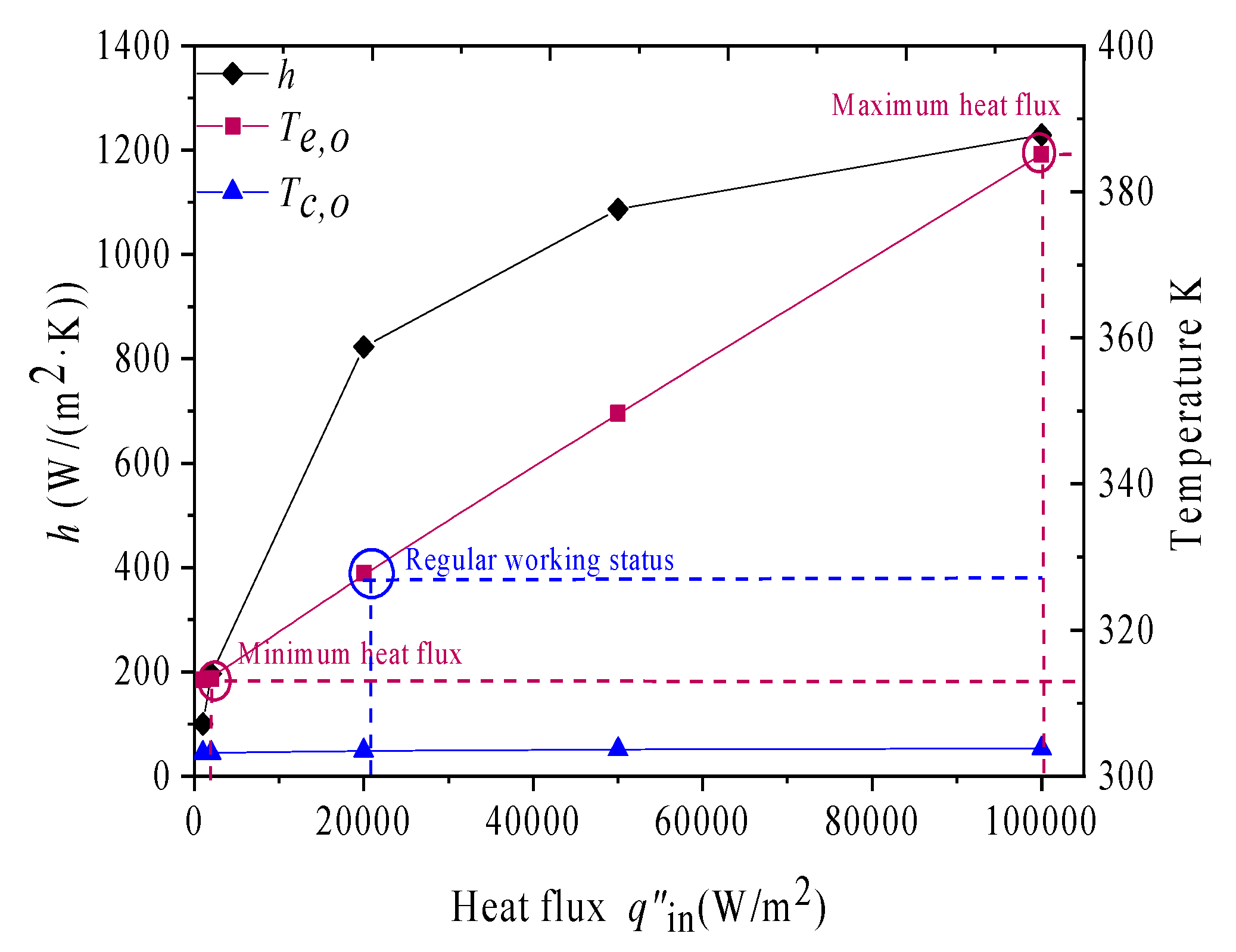
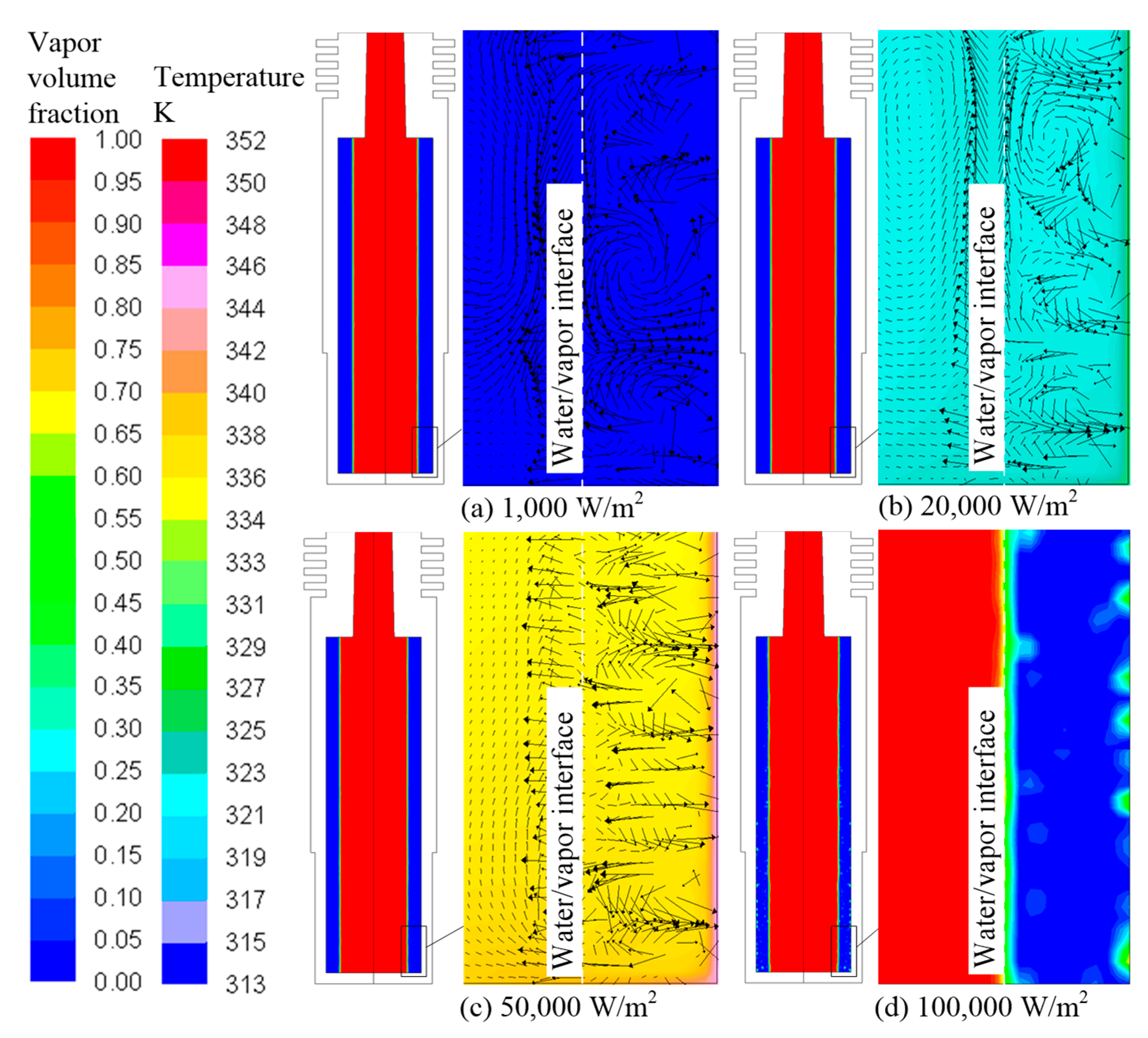
The heat transfer coefficient for heat flux of 2000, 20,000, 50,000 and 100,000 W / m 2 is shown in Figure 3. The heat transfer coefficient increases with the increase of the heat flux. The temperature outside the evaporator is also higher with higher heat flux. This result should be attributed to more fierce convection or boiling heat transfer caused by higher ΔT. Therefore, the heat transfer mechanism in the RHP was analyzed and is shown in Figure 4. The global phase distribution in the RHP is plotted in Fluent and shown in Figure 4, the red color refers to the vapor phase (referenced as value 1 in the first legend), the blue one refers to the liquid phase and the mixture phase is displayed as the color between red and blue. For the cases without bubbles (Figure 4a–c), the local temperature distribution overlaid by velocity vectors are displayed and zoomed on the right. The specific temperature value can be referenced to the second legend.
As the input heat flux increased from 1000 to 50,000 W / m 2 , the convection is dominant in the heat transfer mode, besides, the convection cells gradually turn to smaller and more unsteady convection cells (Figure 4a–c), which leads to better heat transfer performance as reported by Poulikakos [20] and Neshat [21]. As the input heat flux reached 100,000 W / m 2 , boiling occurred in the liquid layer (Figure 4d), leading to a higher heat transfer coefficient.
In addition, during grinding, the temperature in the grinding contact zone was set be controlled below 120 °C. As shown in Figure 3, the temperature outside the evaporator is about 390 K as the heat flux reached 100,000 W / m 2 . Therefore, the maximum heat flux for the RHP-GW should be 100,000 W / m 2 . Furthermore, the temperature outside the evaporator is kept at 313 K, which is also set as the initial temperature. In order to start the RHP, there should be a temperature rise in the evaporator. Hence the input heat flux should be higher than 2000 W / m 2 . Therefore, the RHP-GW should be applied in the range of 2000 to 100,000 W / m 2 .

3.2. Effect of Filling Ratio

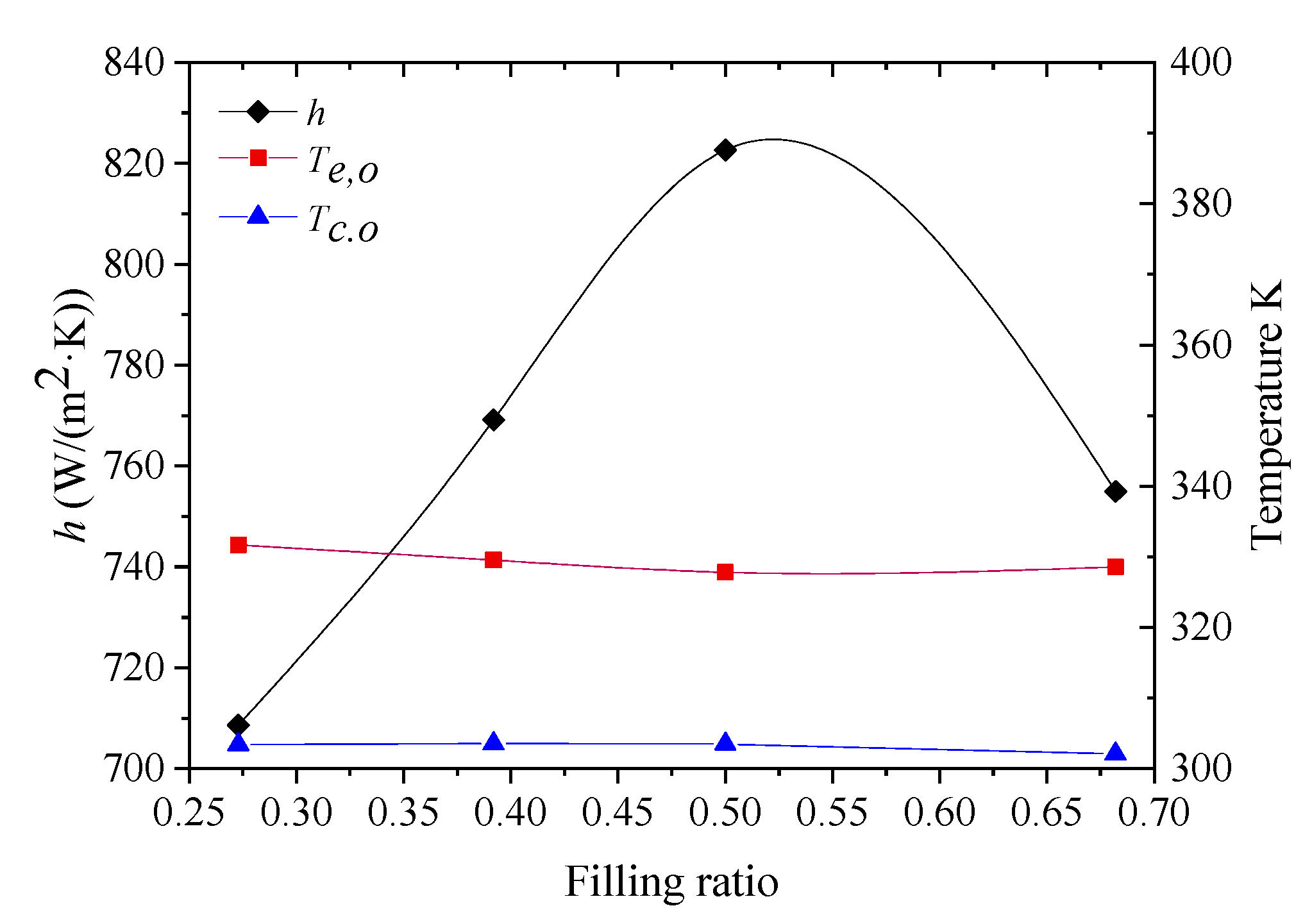
Filling ratio is another effect that will influence the heat transfer performance of RHP-GW, which is defined as the volume ratio of the working fluid and RHP. The simulations were performed under a heat flux of 20,000 W / m 2 . Different filling ratios of 27.3%, 39.2%, 50% and 68.2% were analyzed, which are the equivalent to a film thickness of 1, 1.5, 3 and 3.5 mm.
The best heat transfer performance was found with the filling ratio of 50%, which showed the highest average heat transfer coefficient of 822.6 W / m 2 and the best mean temperature performance with the smallest temperature difference of 24 K (as shown in Figure 5). The convection cells are much more unsteady than the other cases, as shown in Figure 6c, which turned out to facilitate the convection process. Increasing the filling ratio to 68.2% reduces the heat transfer in RHP-GW due to the increase of liquid film thickness, which also covered the condenser section (as shown in Figure 6d) and thus weakened the heat exchange there. Reducing the filling ratio also reduces the heat transfer coefficient because of the “dry-out” of the liquid phase (as shown in Figure 6a), which makes it difficult to achieve a continuous thermal dynamic process.

3.3. Effect of Rotational Speed

Rotational speed was investigated from 1600 to 30,000 rpm. Other conditions are as follows: filling ratio of 50% and input heat flux of 20,000 W / m 2 . The simulation results are shown in Figure 7. As the rotational speed increases from 1600 rpm to 5000 rpm, the average heat transfer coefficient decreases from 910.7 W / ( m 2 · K ) to 833.6 W / ( m 2 · K ) , which decreases by nearly 9%. This is because the nucleate boiling in the evaporator was suppressed gradually as the rotational speed increases, as shown in Figure 8a,b. When the rotational speed increases from 5000 rpm to 30,000 rpm, the averaged heat transfer coefficient decreases slowly from 833.6 W / ( m 2 · K ) to 822.6 W / ( m 2 · K ) . According to Figure 8b–d, although increasing the rotational speed suppresses nucleate boiling, convection heat transfer increases because of the higher rotational speed.
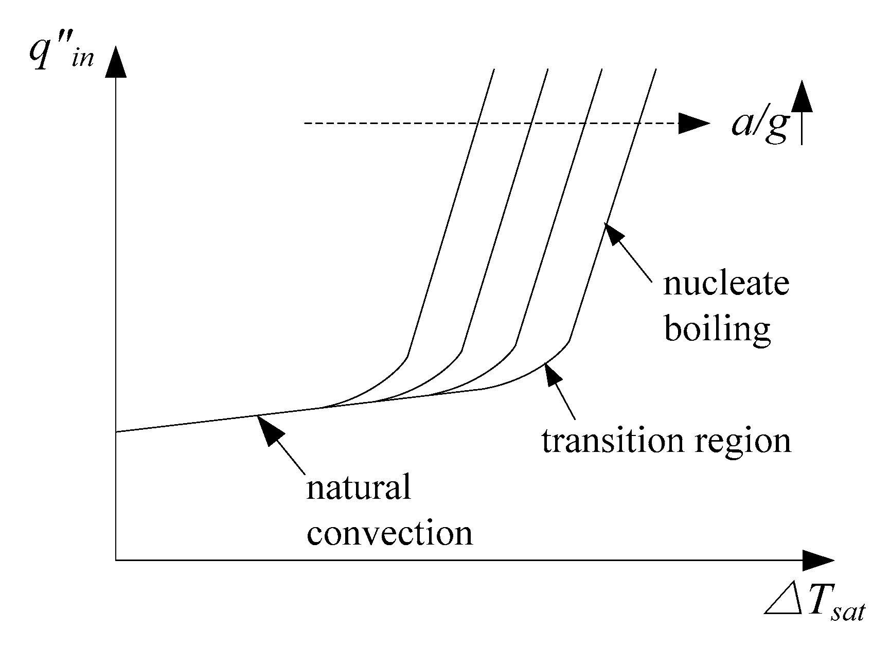
In addition, as the rotational speed rises, the liquid distribution changes from partial annular flow to fully developed annular flow (Figure 8a–c). Obvious nucleate boiling can be found with a rotational speed of 1600 rpm. When the rotational speed rises, nucleate boiling disappeared gradually, especially when the rotational speed is higher than 20,000 rpm. According to Vasiliev and Khrolenok [22], as the rotational speed rises, higher Δ T s a t ( Δ T s a t   =   T l o c a l T s a t ) is required to induce nucleate boiling (as shown in Figure 9). Therefore, higher acceleration calls for higher input heat flux, meaning that under the same input heat flux, increasing the rotational speed tends to suppress the nucleate boiling phenomenon.

4. Validation

4.1. Experimental Conditions

In order to verify the superior cooling effect of RHP-GW and for validation of the simulation method, a dry grinding experiment was carried out. The grinding experiment was carried out on a milling machine, and the experimental setup is shown in Figure 10.
Two pieces of Ti-6Al-4V with a length of 140 mm and 10 mm were pieced together. A thermocouple was embedded between the two workpieces, which will be used to catch the grinding temperatures in the contact zone. The longer workpiece was ground first to provide enough time for the startup of the RHP. A vortex tube was set outside the condenser to provide a cold air of about 4.5 °C with an error of about ±0.1 °C. Three thermocouples were embedded on the RHP inner wall to test the temperature distributions inside the heat pipe. The uncertainty of the thermocouples is less than 5%. An electric brush and slip ring system were applied to measure the rotating temperature signals inside the RHP. Grinding parameters were selected according to the simulation results. A rotational speed of 5000 rpm, a filling ratio of 50%, a workpiece speed of 40   mm / min and a cutting depth of 0.1 mm was applied.

4.2. Temperature Distribution in the RHP

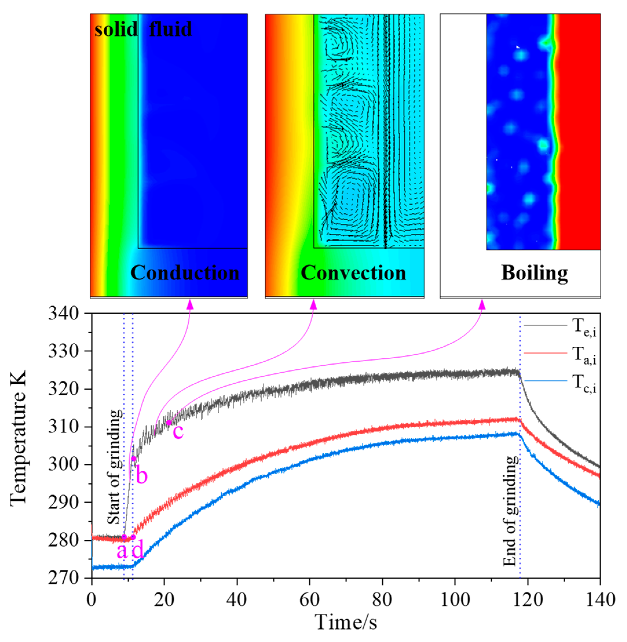
Figure 11 shows the temperature variation on the inner wall of the RHP. According to the temperature curve, the startup time of the RHP-GW was about 60 s. The temperature variation reflects the startup process of the RHP inside the grinding wheel. During grinding, three distinctive stages can be identified. The first stage (from point a to point b) can be treated as an unsteady lumped heat conduction, which took place through the composite layer of grains and wheel matrix, therefore an exponential temperature increase was found. Since the layer of the matrix was thin, this stage lasted only 3 s. It should also be noticed that there was a time lag of about 3 s for the temperature signals on the adiabatic and condenser sections (from point a to point d), which was in accord with the heat conduction time in the solid grinding wheel matrix in the first stage. Then, the temperature increasing rate decreased gradually due to the convection heat transfer in the liquid layer (from point b to point c). Finally, boiling occurs and the temperature is stabilized at about 321 K without demonstrating any oscillation and overshoot. The start-up process turned out to be in reasonable agreement with the simulation results.
The temperature distribution in the RHP at the steady state was compared with the simulation results under the same condition with a filling ratio of 50% and a rotational speed of 5000 rpm, as shown in Figure 12. The significant temperature fluctuation obtained by simulation can be found in the evaporator section, which should be caused by the natural convection and boiling inside the liquid layer. The temperature distribution becomes smoother in the adiabatic section and condenser section. The prediction of the overall temperature distribution by the simulation was in good agreement with the experimental result with a maximum error of 0.5%. Therefore, the simulation method applied in this investigation is capable of predicting the heat transfer performance of the RHP-GW, which will highly improve the research efficiency and lower the manufacturing costs.

4.3. Temperature in the Grinding Contact Zone

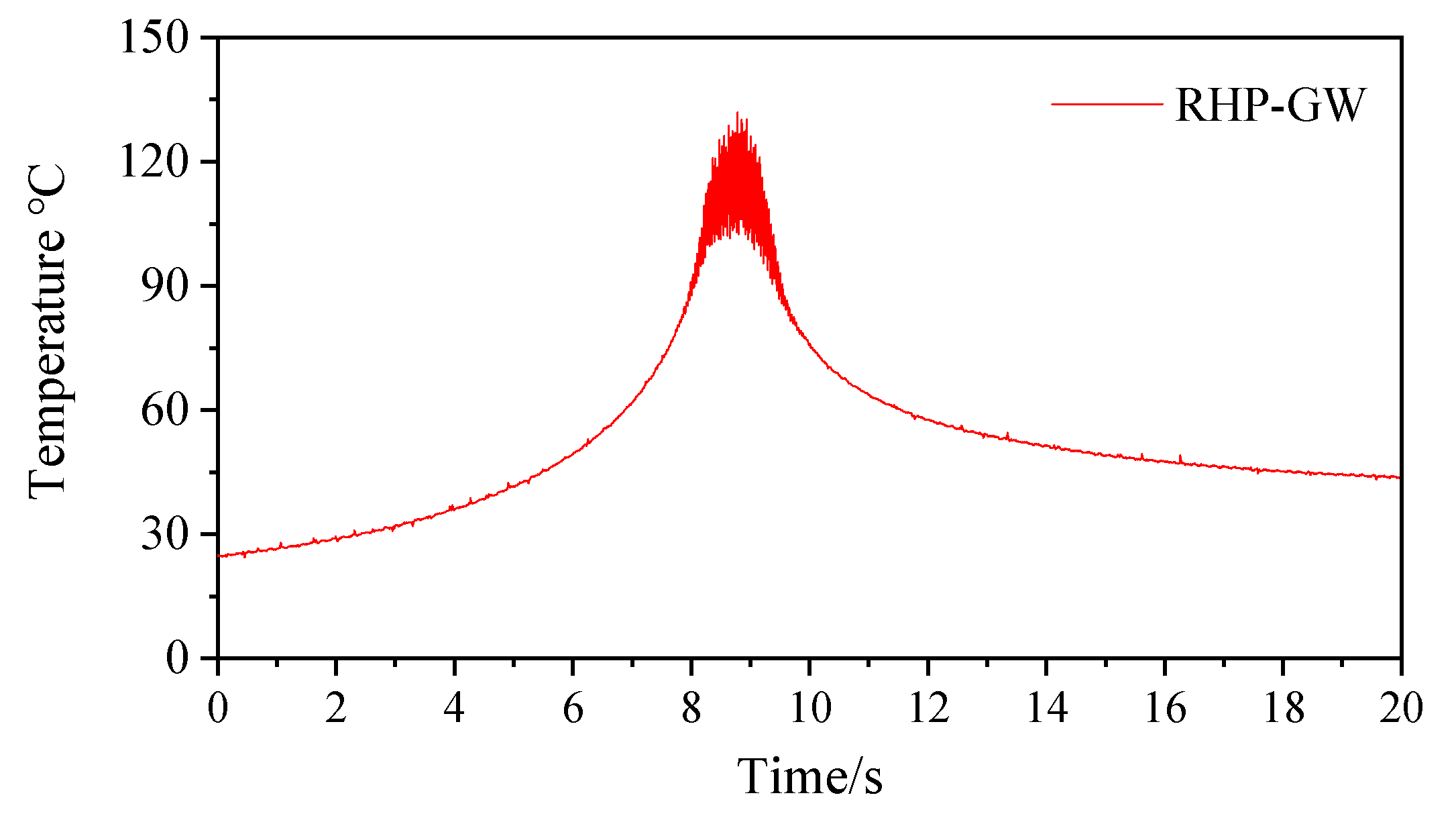
The grinding temperature was shown in Figure 13, the sharp value shows the grinding temperature on the grains and the lower enveloping curve shows the average grinding temperature in the contact zone. The average grinding temperature in the contact zone can be controlled under 100 °C. During dry grinding, the grinding heat is usually transfer by the chips, the workpiece and the grinding wheel. The heat transferred by the chips is limited due to the chip formation energy. The proportion that transferred by the workpiece is very small because of its low thermal conductivity. Therefore, the averaged grinding temperature is determined by the proportion that is transferred by the grinding wheel. When RHP was formed, the thermal conductivity of the grinding wheel matrix was highly improved, which contributes to a low average grinding temperature.
Observations of the workpiece ground surface was carried out, as shown in Figure 14. The surface of the workpiece was smooth without any burnt color. The microstructure of the workpiece beneath the ground surface was observed. The grains in the ground layer was almost identical with the bulk material, which means that the grinding temperature was successfully controlled by the RHP in the grinding wheel. Besides, the conclusion can be also drawn that the optimized parameters that obtained by simulation was suitable for the RHP-GW.

5. Conclusions

In this paper, a two-phase flow simulation based on the VOF method was complemented for the RHP-GW. The overall heat transfer is solved for different input heat flux, filling ratio and rotational speed. Validation experiments were carried out by the dry grinding of Ti-6Al-4V, both the temperature in the RHP and the grinding contact zone were tested. The main conclusions can be drawn as follows:
(1)
The appropriate heat flux for the new tool ranges from 2000 to 100,000 W / m 2 . An ideal filling ratio of about 50% was determined with a heat transfer coefficient of 822.6 W / ( m 2 · K ) . The heat transfer coefficient decreased with the rise of the rotational speed because nucleate boiling was gradually replaced by convection heat transfer.
(2)
A consistent temperature distribution and start-up process including conduction, convection and boiling were found in both simulation and experiment results. The start-up time for the RHP-GW with filling ratio of 50%, a rotational speed of 5000 rpm and a cutting depth of 0.1 mm was about 60 s.
(3)
The grinding temperature in the contact zone was controlled below 100 °C and the microstructure of the workpiece beneath the ground layer was found to be consistent with the bulk material.
Therefore, it is of great prospect to realize green grinding by incorporating an axially RHP in the grinding wheel.

Author Contributions

Conceptualization: J.C. and Y.F.; methodology and analysis: J.C. and H.J.; writing—original draft preparation: J.C., H.J. and N.Q.; writing—review and editing: Y.F.; supervision: Y.F.; funding acquisition: J.C. All authors have read and agreed to the published version of the manuscript.

Funding

The authors gratefully acknowledge the financial support for this work by the National Natural Science Foundation of China [51905275], Natural Science Foundation of Jiangsu Province [BK20190752], Natural Science Research of Jiangsu Higher Education Institutions of China [19KJB460020] and the Faculty Research Funding of Nanjing Forestry University [163040111].

Acknowledgments

The authors would like to address a great thank to Jiusheng Xu for his assistant to build the apparatus.

Conflicts of Interest

The authors declare no conflict of interest.

Nomenclature

hheat transfer coefficient: W/(m2∙K)
LHlatent heat of working fluid, KJ/kg
Plocal pressure, Pa
qheat flux, W/m2
Ssource term
Ttemperature, °C
ΔTtemperature difference
Greek
ρdensity, kg/m3
αvolume fraction of liquid phase
σinterfacial surface tension, N/S
Subscripts
ininput
cooutside the condenser section
eooutside the evaporator section
ECheat transfer of condensation
EEheat transfer of evaporation
Lliquid phase
mmomentum
mixmixture of liquid and vapor
MLmass transfer of liquid
MVmass transfer of vapor
satsaturate
Vvapor phase

References

  1. Rajesh, B.; Amit, R.D.; Arun, K.T. Machining performance enhancement of powder mixed electric discharge machining using Green dielectric fluid. J. Braz. Soc. Mech. Sci. 2020, 42, 512. [Google Scholar]
  2. Ma, C.; Duan, Y.; Yu, B.; Sun, J.; Tu, Q. The comprehensive effect of surface texture and roughness under hydrodynamic and mixed lubrication conditions. Proc. Inst. Mech. Eng. Part J J. Eng. Tribol. 2017, 231, 1307–1319. [Google Scholar] [CrossRef]
  3. Barczak, L.M.; Batako, A.D.L.; Morgan, M.N. A study of plane surface grinding under minimum quantity lubrication (MQL) conditions. Int. J. Mach. Tools Manuf. 2010, 50, 977–985. [Google Scholar] [CrossRef]
  4. Wei, W.; Li, Y.; Xue, T.; Tao, S.; Mei, C.; Zhou, W.; Wang, J.; Wang, T. The Research Progress of Machining Mechanisms in Milling Wood-based Materials. Bioresources 2018, 13, 2139–2149. [Google Scholar] [CrossRef]
  5. Gugulothu, S.; Pasam, V.K. Testing and Performance Evaluation of Vegetable-Oil-Based Hybrid Nano Cutting Fluids. J. Test. Eval. 2020, 48, 3839–3854. [Google Scholar] [CrossRef]
  6. Rabiei, F.; Rahimi, A.R.; Hadad, M.J. Performance improvement of eco-friendly MQL technique by using hybrid nanofluid and ultrasonic-assisted grinding. Int. J. Adv. Manuf. Tech. 2017, 93, 1001–1015. [Google Scholar] [CrossRef]
  7. Sen, B.; Gupta, M.K.; Mia, M. Wear behavior of TiAlN coated solid carbide end-mill under alumina enriched minimum quantity palm oil-based lubricating condition. Tribol. Int. 2020, 148, 106310. [Google Scholar] [CrossRef]
  8. Ponnappan, R.; Leland, J.E. Rotating heat pipe for high speed motor/generator cooling. SAE Trans. 1998, 107, 257–262. [Google Scholar]
  9. Daniels, T.C.; Williams, R.J. Experimental temperature distribution and heat load characteristics of rotating heat pipes. Int. J. Heat Mass Transf. 1978, 21, 193–201. [Google Scholar] [CrossRef]
  10. Song, F.; Ewing, D.; Ching, C.Y. Fluid flow and heat transfer model for high-speed rotating heat pipes. Int. J. Heat Mass Transf. 2003, 46, 4393–4401. [Google Scholar] [CrossRef]
  11. Judd, R.L.; Aftab, K.; Elbestawi, M.A. An investigation of the use of heat pipes for machine tool spindle bearing cooling. Int. J. Mach. Tools Manuf. 1994, 34, 1031–1043. [Google Scholar] [CrossRef]
  12. Jen, T.C.; Gutierrez, G.; Eapen, S. Investigation of heat pipe cooling in drilling applications-Part(I): Preliminary numerical analysis and verification. Int. J. Mach. Tools Manuf. 2002, 42, 643–652. [Google Scholar] [CrossRef]
  13. Liu, D.; Ling, X.; Peng, H.; Li, J.; Duan, L. Experimental and numerical analysis on heat transfer performance of slug flow in rectangular microchannel. Int. J. Heat Mass Transf. 2020, 147, 118963. [Google Scholar] [CrossRef]
  14. Asmaie, L.; Haghshenasfard, M.; Mehrabani-Zeirabad, A.; Esfahany, M.N. Thermal performance analysis of nanofluids in a thermosyphonheat pipe using CFD modeling. Heat Mass Transf. 2013, 48, 66–78. [Google Scholar]
  15. Kenjeres, S.; Hanjalic, K. Convective rolls and heat transfer in finite-length Rayleigh-Benard convection: A two-dimensional numerical study. Phys. Rev. E 2000, 62, 7987–7998. [Google Scholar] [CrossRef] [Green Version]
  16. Kafeel, K.; Turan, A. Axi-symmetric simulation of a two-phase vertical thermosyphon using eulerian two-fluid methodology. Heat Mass Trans. 2013, 49, 1089–1099. [Google Scholar] [CrossRef]
  17. Chen, J.J.; Fu, Y.C.; Gu, Z.B.; Shen, H.F.; He, Q.S. Study on heat transfer of a rotating heat pipe cooling system in dry abrasive-milling. Appl. Therm. Eng. 2017, 115, 736–743. [Google Scholar] [CrossRef]
  18. Fadhl, B.; Wrobel, L.C.; Jouhara, H. Numerical Modeling of the Temperature Distribution in a Two-phase Closed Thermosyphon. Appl. Therm. Eng. 2013, 60, 122–131. [Google Scholar] [CrossRef] [Green Version]
  19. De Schepper, S.C.K.; Heynderickx, G.J.; Marin, G.B. Modeling the evaporation of a hydrocarbon feedstock in the convection section of a steam cracker. Comput. Chem. Eng. 2009, 33, 122–132. [Google Scholar] [CrossRef]
  20. Poulikakos, D.; Bejan, A. Unsteady natural convection in a porous layer. Phys. Fluids 1983, 26, 1183–1191. [Google Scholar] [CrossRef]
  21. Neshat, E.; Hossainpour, S.; Bahiraee, F. Experimental and numerical study on unsteady natural convection heat transfer in helically coiled tube heat exchangers. Heat Mass Transf. 2014, 50, 877–885. [Google Scholar] [CrossRef]
  22. Vasiliev, L.L.; Khrolenok, V.V. Centrifugal coaxial heat pipes. In Proceedings of the 2nd International Heat Pipe Conference, Bologna, Italy, 31 March–2 April 1976; pp. 293–302. [Google Scholar]
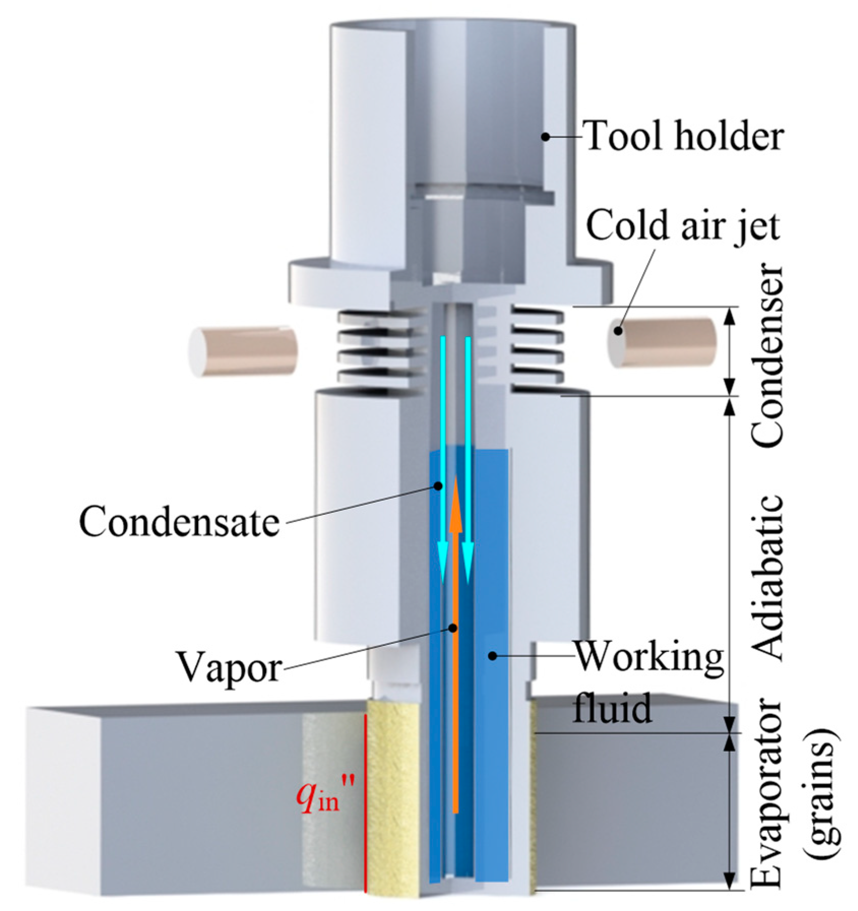
Figure 1. Schematic of RHP-GW.
Energies 13 05745 g001
Figure 2. Simulation model (a) and boundary conditions (b).
Energies 13 05745 g002
Figure 3. Heat transfer performance under different input heat flux.
Energies 13 05745 g003
Figure 4. Heat transfer mechanism under different input heat flux.
Energies 13 05745 g004
Figure 5. Heat transfer performance under different filling ratio.
Energies 13 05745 g005
Figure 6. Heat transfer mechanism under different filling ratio.
Energies 13 05745 g006
Figure 7. Heat transfer performance under different rotational speeds.
Energies 13 05745 g007
Figure 8. Heat transfer mechanism under different rotational speeds.
Energies 13 05745 g008
Figure 9. Relationship between heat transfer mechanisms and acceleration [22].
Energies 13 05745 g009
Figure 10. Experimental setup.
Energies 13 05745 g010
Figure 11. Startup process of RHP-GW.
Energies 13 05745 g011
Figure 12. Comparison of the temperature distribution along the wall between the simulation and validation experiment.
Energies 13 05745 g012
Figure 13. Grinding temperatures in the grinding contact zone.
Energies 13 05745 g013
Figure 14. Workpiece surface (a) photograph; (b) microstructure beneath the ground surface.
Energies 13 05745 g014
Table 1. Source terms during phase change process.
Phase Change ProcessSource Terms
Evaporation ( T m i x   >   T s a t ) S M L   = 0.1 ρ L α L T m i x T s a t T s a t
S M V   = 0.1 ρ V α V T m i x T s a t T s a t
S E E = 0.1 ρ L α L T m i x T s a t T s a t L H
Condensation   ( T m i x   <   T s a t ) S M L = 0.1 ρ L α L T s a t T m i x T s a t
S M V = 0.1 ρ V α V T s a t T m i x T s a t
S E C   = 0.1 ρ V α V T s a t T m i x T s a t L H
Publisher’s Note: MDPI stays neutral with regard to jurisdictional claims in published maps and institutional affiliations.