Article

Photovoltaic Concentration: Research and Development

1
Laboratory of Intelligent Systems, Georesouces and Renewable Energies (SIGER), Faculty of Sciences and Technologies, Sidi Mohammed ben Abdellah University, P.O. Box 2202 Fez, Morocco
2
Unité Mixte Internationale (UMI 2958), 2–3 rue Marconi, Georgia Tech Lorraine, 57070 Metz, France
3
School of Electrical and Computer Engineering, Georgia Institute of Technology, Atlanta, GA 30332, USA
*
Author to whom correspondence should be addressed.
Associate researcher.
Energies 2020, 13(21), 5721; https://doi.org/10.3390/en13215721
Submission received: 26 August 2020 / Revised: 30 September 2020 / Accepted: 9 October 2020 / Published: 2 November 2020
(This article belongs to the Special Issue Advances in Concentrator Photovoltaics Technology)

Abstract

:
Concentrator Photovoltaic (CPV) technology, by using efficient optical elements, small sizes and high efficiency multi-junction solar cells, can be seen as a bright energy source to produce more cost-effective electricity. The main and basic idea is to replace the use of expensive solar cells with less expensive optical elements made from different materials. This paper aims to give to the readers a rapid and concise overview of CPV and the main characteristics to be considered when designing a CPV system. It reviews the main optical configurations presented in the literature, their advantages and drawbacks, as well as the recent progress in the concentration ratio and the major performances achieved in the field. The paper considers the more recent works, their optical designs, as well as their optical and electrical performances. It also relates the major achievements on the industrial side with the major milestones in CPV developments.

Graphical Abstract

1. Introduction

The most dominant Photovoltaic (PV) plants on the market (85%) are the crystalline silicon solar cells (Si-PV), due to the abundance of silicon dioxide (SiO 2 ) and its low cost of manufacturing. However, those cells’ efficiencies are still relatively low (maximum theoretical efficiency in the range of 33%). Hence, many technologies and materials have been proposed to boost efficiency.
One of those new technologies is the Multi-Junction (MJ) cells that can absorb a wider wavelength spectrum thanks to the stacking of different semiconductor materials, with several band gaps, in a cell. These cells’ efficiencies are twice or even more as high as those of silicon cells, but they are both more expensive and hard to manufacture. One other major indicator that investors are interested in is also the cost of energy production, the Levelized Cost of Electricity (LCOE) expressed in $ / k W h . Energy with a very low LCOE allows a quick return on investment. Manufacturing costs must be low and the efficiency of the facility high. In this sense, solar concentration is a relevant solution for the integration of MJ cells in photovoltaic energy production.
Concentrator Photovoltaic (CPV) systems use refractive and/or reflective non-imaging optical components to direct sunlight onto solar cells. In this way, a received flux on a given large surface of an optical receiver is concentrated on a highly reduced area, corresponding to the solar cell and producing the same energy or even more than the same production with the equivalent Si-PV surfaces. It then makes it possible to reduce the area of the solar cells used per module thanks to the increased received flux given by the surface ratio between the optical receiver and the solar cell, defined as the geometrical concentration of the module. This structural aspect allows CPV systems to achieve higher energy conversion efficiency at continuously lowered cost than other photovoltaic technologies. However, this technology exploits only direct incident solar radiation, compared to the classical PV systems, where diffused and albedo radiation can also be exploited; thus, it is necessary to continuously face the Sun, which requires Sun motion tracking.
The main idea of CPV was introduced for the first time by Shockley and Queisser in 1961. After having obtained a maximum conversion efficiency of about 30% for mono-junction solar cells under an illumination of 1000 W / m 2 , they concluded that the cells’ efficiency can be highly improved with the increase of incident light density on the cell and were then the first ones to mention the boost of cells’ efficiency using a CPV solution [1].
The first CPV system delivering a power of one kilowatt peak 1 ( k W p ) was developed at Sandia lab in New Mexico in 1976 [2]. The Polytechnic University of Madrid immediately followed this initiative and developed a similar system in 1980. Both of those systems were based on the use of Fresnel lenses, silicon solar cells with a concentration ratio of 40 × and a dual-axis solar tracker to monitor the DNI all day long. The 40 × means that the density of received photons on the cell corresponds to 40 times that of the Sun (1000 W / m 2 ). In 1990, a CPV system was industrialized for the first time in Texas by ENTECH with a few hundred k W p , using curved Fresnel lenses, at a concentration of 20 × . The progress of CPV systems saw a leap forward with the appearance of the GaAs mono-junction, in 2001, which allows a high concentration of around 1000 × with an efficiency of 26%. Moreover, the revolution of those systems started in 2005 by the use of triple junction solar cells, reaching an efficiency of 35.2%. 2006 saw the launch of the first project exceeding 1 M W in Spain, and since then, various projects have emerged all over the world: The “Golmud 1” project, of a capacity of 58 MW, was installed in 2012, in China. Its capacity was increased in 2013 to 79.8 M W . The “Touwsrivier” project was installed in South Africa by 2014, with a total power of about 44.2 M W , and in 2016, Sumitomo set up a 1 M W CPV plant in Morocco.
Optical concentration systems can be refractive or reflective and can contain several “concentration stages” with first a Primary Optical Element (POE) and, according to the design criteria, a Secondary Optical Element (SOE), while even in a few cases, three elements [3]. Those optical elements are generally manufactured using several material such as PMMA, BK7, metal, etc.
This paper reviews the main optical configurations recently presented in the literature, their advantages and drawbacks, as well as the recent progress in the concentration ratio and the major performances achieved in the CPV field. The rest of the paper is organized as follows: We start by giving some definitions for unaccustomed users, and then, in Section 3, we present and discuss the solar concentrator designed using one optical element. In Section 4, we focus on two or more stage concentrators, and in Section 5, we present the conclusion.

2. Basic Concepts for Solar Concentrators

2.1. Non-Imaging Optics

This theory was developed in the mid-1960s simultaneously in the USSR, Germany and the USA, respectively by V. K. Baranov [4] with the study of the focusing cones [5], Martin Ploke [6] and Roland Winston (United States) [7], and is the most used to today. Anidolic optics seeks to optimize the lighting produced by a source on a target without worrying about forming an image of the source. Instead of forming an image, one has to ensure that the extreme rays, travelling at extreme directions and or emanating from extreme positions at the entrance aperture of the optical system, are directed to the extreme directions and or extreme positions at the absorber, as shown in Figure 1. In this figure, we have a lighting source EF, an optical system and a receiver AB. In Figure 1a, the radiation emitted from Point F and Point E of the source must be focused, respectively, at Points A and B on the receiver, and the radiation emitted from the intermediate zones must, thanks to the design of the optical system, fall somewhere over the entire zone AB of the receiver. In contrast, in Figure 1b, in addition to the fact that the light coming from Points F and E must be focused respectively on Points A and B of the image, this condition would always be valid for any point P of the object. Thus, the distance between the optical axis and the point P in the object plan, d 0 , on the one hand, and the point Q and the optical axis, on the other hand, in the image plan, d i are related by Equation (1):
d 0 = M d i
with M the magnification of the optical system. This condition results in an image, accurately reproducing the object by preserving the relative dimensions of its several parts.

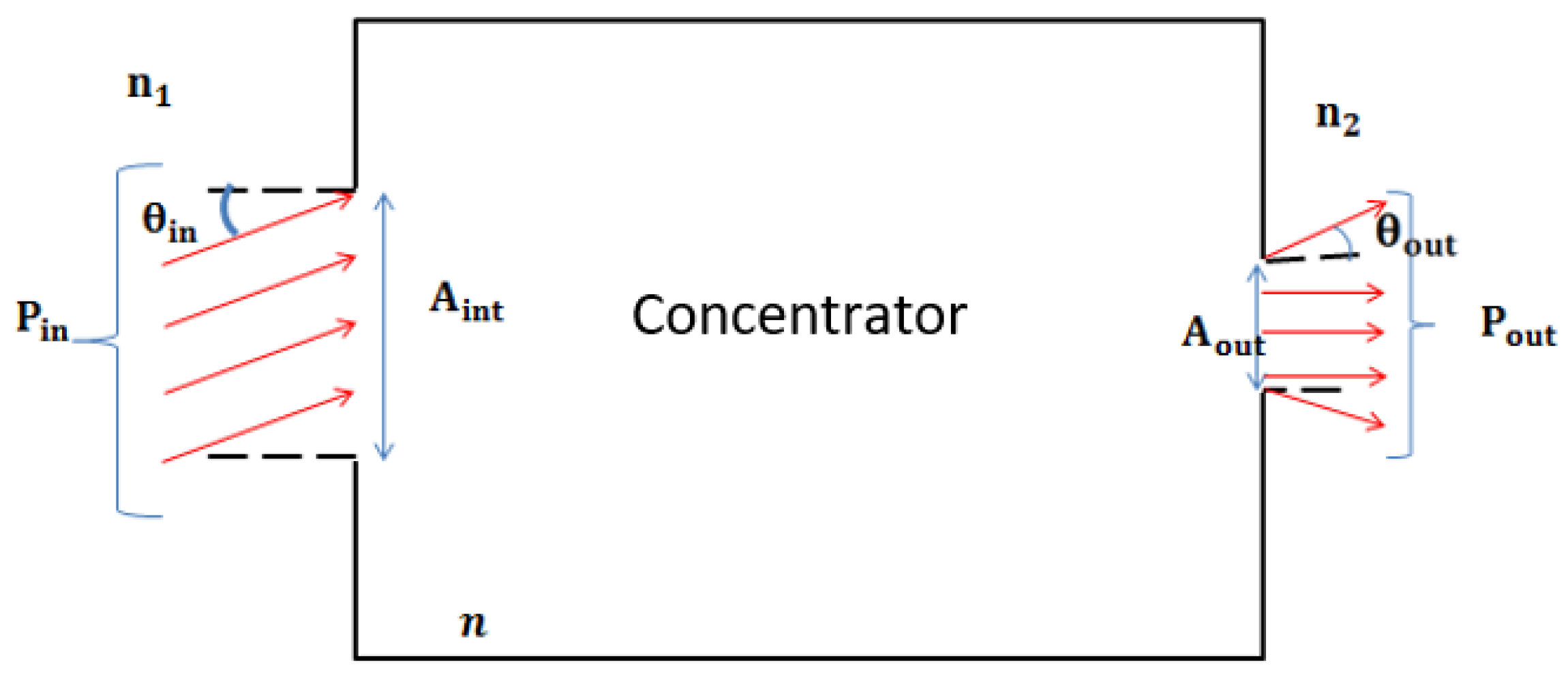
2.2. Concentration Ratio

Figure 2 shows a typical view of an optical system separating two mediums with refractive indexes n 1 and n 2 respectively for the entrance and exit environment.
The whole concentration ratio of the system is defined as:
C = η × C g
where η denotes the optical efficiency given by:
η = P o u t P i n
and C g the geometrical concentration defined by the ratio of entrance and exit surfaces given by:
C g = A i n A o u t = n 2 sin θ o u t n 1 sin θ i n
In Equation (4), the second term is obtained using the étendue law [8]. A i n is the entrance aperture area, A o u t the exit area, generally equal to the receiver area, P i n and P o u t , respectively, the power at the entrance and the exit of the system, θ i n the incidence angle at the system entrance and θ o u t the output angle defined as the angle between the normal to the exit surface and the emerging optical ray.

2.3. Principal Characteristics of an Optical Concentrator

The concentrating elements must be designed according to non-imaging optic principles. They must be designed in order to maintain a uniform irradiation of the cell, both in terms of the spectral and light intensity distributions. Furthermore, another crucial factor, known as the acceptance angle, has to be as wide as possible to minimize the tracking errors of the systems. All these factors generate more complexity and additional cost, hence the need to develop new structures and investigate new methodologies in order to master them and to reduce and even limit their effects.
For CPV technology, the notion of the acceptance angle is introduced, and one has to distinguish between two variants, an acceptance angle of the module and another for the optical system.
  • Acceptance angle of a module:
    The acceptance angle or tolerance angle is a quantity that characterizes the angular tolerance of a module to misalignment between its normal and the perpendicular incident solar rays, generally defined as the maximum full angle through which the module can be rotated (with respect to the Sun) while continuing to produce 80% of its DNI normalized maximum power, as shown in Figure 3.
  • Acceptance angle of an optical element:
    The acceptance angle of an optical element is the maximum angle within which the incoming solar rays can be sent back to the receiver. As shown in Figure 4, for a given acceptance angle θ , light rays coming with an angle smaller than or equal to θ can reach the receiver, otherwise the ray returns to the entrance.
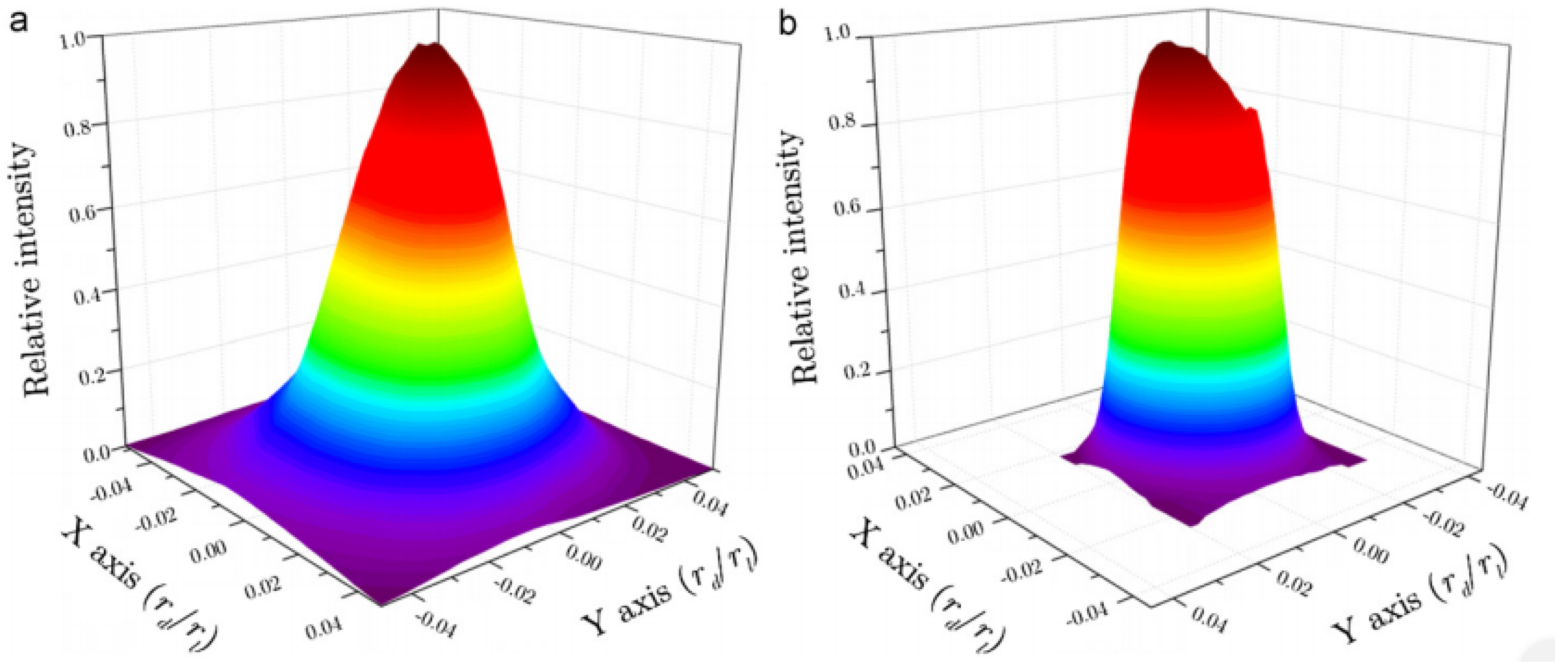
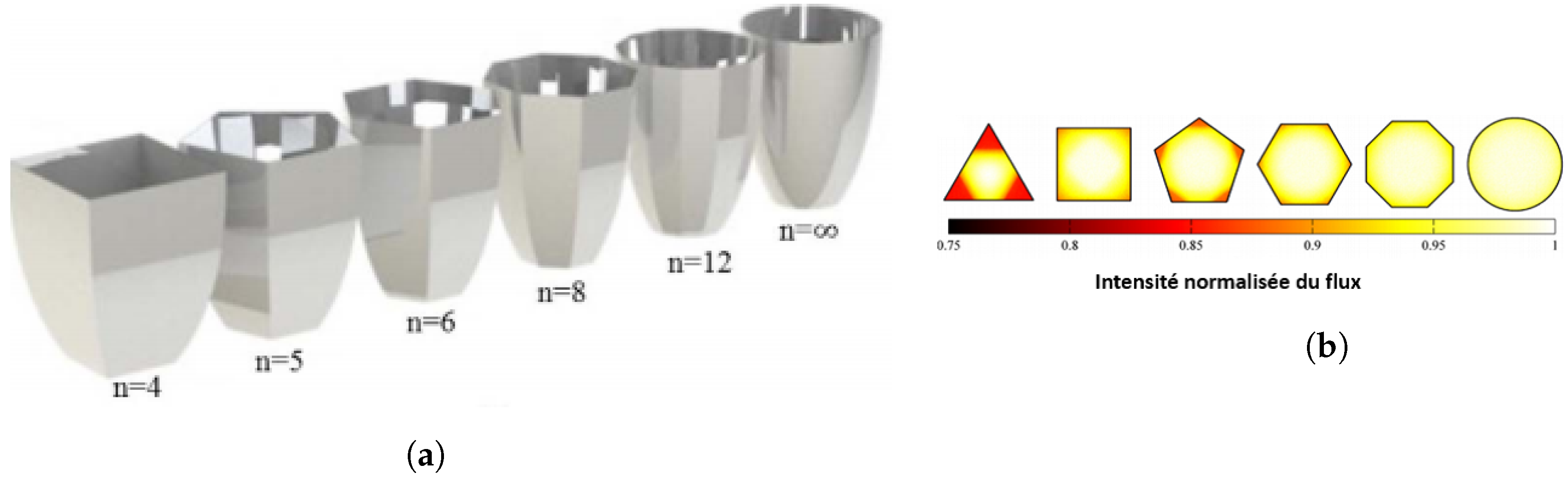
  • Homogeneity of the illumination flux:
    The homogeneity of the flux at the cell surface is also an important characteristic for CPV technology, since the optical elements can create in some cases a non-uniform light spot on the cell, leading to a non-uniform response of the solar cell. This induces a noticeable decrease of the system efficiency and even completely damages the cell if the spot intensity is locally so high. In the case of refractive elements, chromatic aberrations add also spectral non-uniformities to the spatial inhomogeneities. Then, each point of the cell receives a different spectrum, and consequently, the produced current varies. These non-uniformities lead to various losses, caused namely by the localized excess current that accentuates the series resistance effects and the locally increased temperature (Kurtz, 1996). Furthermore, the spectral inhomogeneity induces the limitation of the current, which varies spatially, making certain areas of the cell limited by the top sub-cell, for example, and other areas by the middle sub-cell [8].
In general, according to the literature, CPV systems can be classified into two main categories depending on their geometry configuration and on their concentration ratio, as shown in Figure 5. For the geometry side, they can then be split into one or two stage concentrators, each one formed by a lens, mirror or other optical form and/or the association of two or more of them. For the concentration ratio, one can distinguish the low concentration systems under 10 times the Sun (<10×). They have more flexibility for Sun tracking and can run without trackers for a long period of the day. Some low concentration systems do not even use lenses or mirrors, but instead, they use diffuse reflectors or TIR to concentrate light to the silicon solar cell [9].
The second class is the qualified medium concentration systems, with a concentration ratio between 10 and 100 Suns. These systems often use single-junction silicon or GaAs solar cells, which are low cost and therefore constitute the main advantage of this kind of system. However, those cells are very sensitive to heat, and their efficiency decreases quickly with temperature. This issue has widely been resolved by active cooling methods where larger fins of heat dissipation are necessary. This increases the overall cost of the system and decreases its reliability. Medium concentration systems are generally divided into two groups: cylindroid-parabolic concentrator systems and those using Fresnel optics in the form of lenses or mirrors. These systems require one or two axis solar tracking. The last category is the High Concentrator PV systems (HCPV), which are not only the most dominant in CPV technology today, but are the most promising line of research for CPV systems. The optical design and high precision tracking remain the basic requirements for efficient HCPV systems. The two axis tracking system with high accuracy ensures the system positioning so that its surface is still at all times in normal incidence conditions with regard to direct Sun rays.
After having distinguished these concentrations level, now we focus on the details of the optical elements used for the major CPV systems.

3. One Stage CPV Concentrators

Light concentration on solar cells in one stage configurations can be performed through a reflective optical element (mirror), refraction (lens), luminescence and TIR (compound parabolic concentrator, homogenizer, cone, etc.) or any other element allowing the concentration of a large area of collected solar radiation on a small receiver area.

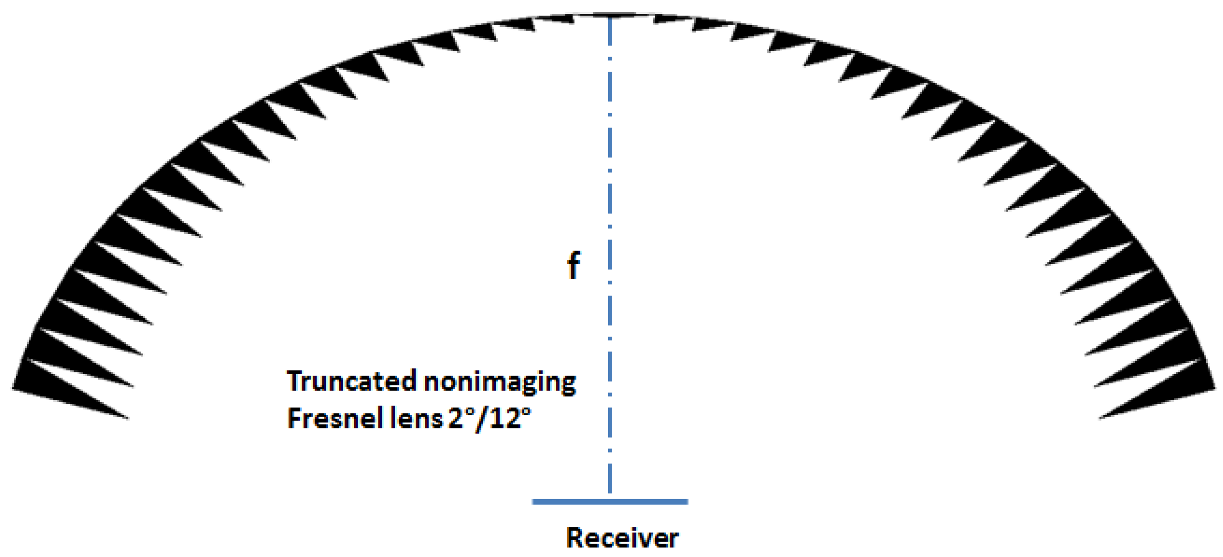
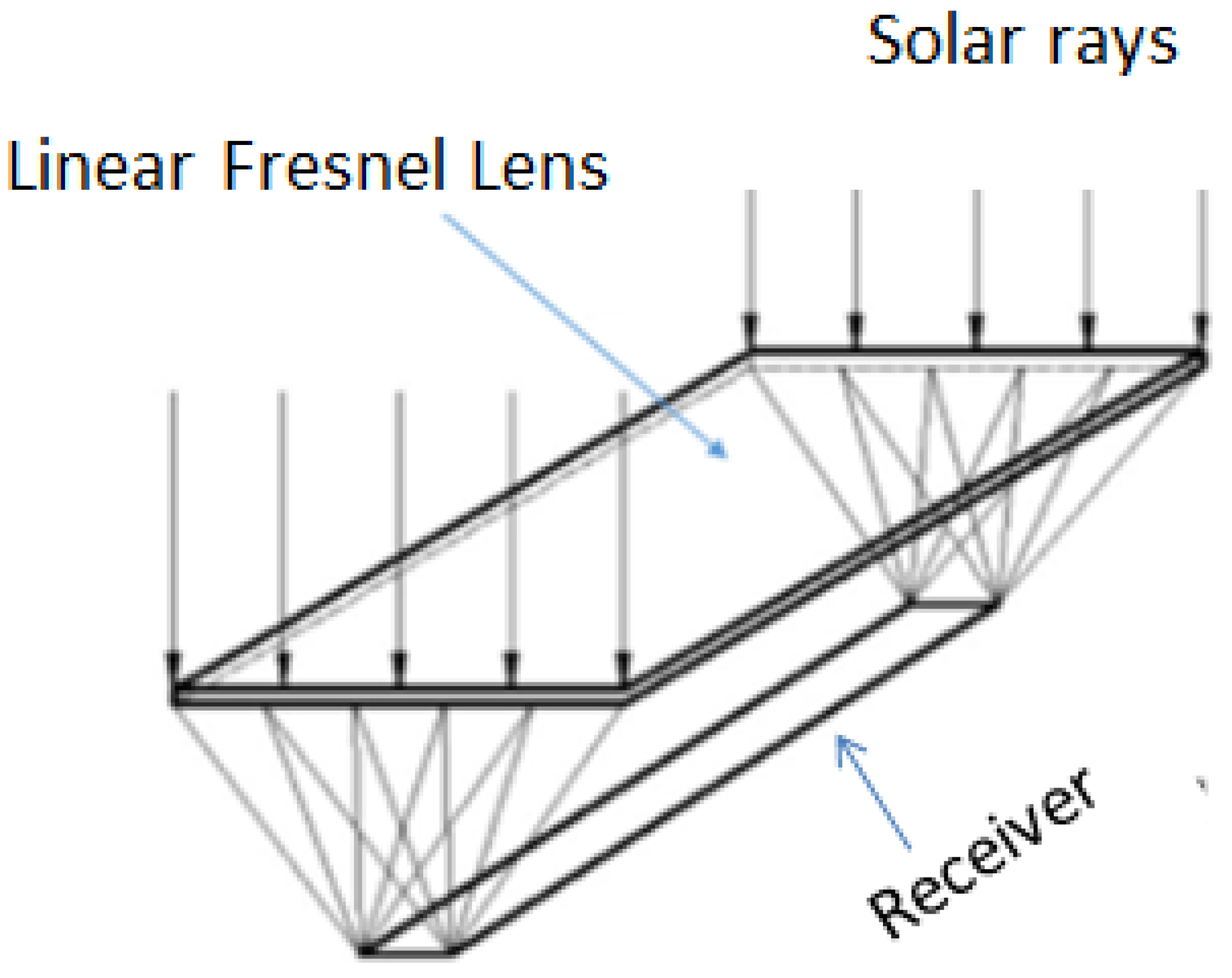
3.1. Fresnel Lens Concentrators

The Fresnel lens is a lens that generally shows a flat face and a face formed by several annular sections, forming inclined facets. It is defined by its diameter, its focal distance and its number of facets per unit of length. The Fresnel lens is considered as the most used optical element in CPV systems, focusing the light at a point or on a larger band. The main advantage of the Fresnel lens is the possibility to have a larger diameter with a short focal length. This is characterized by f # , defined by the ratio of the focal length to the lens diameter ( f # = f / D ).
This element has been used in different forms: the circular and rectangular flat shapes that were studied by Arthur Davis [10]. He reported a marginally better transmittance (82%) for a circular lens vs. a squared ones (80%) in a study of variously shaped Fresnel lenses for CPV systems. El Himer et al. [11] studied the effect of the focal length of the Fresnel lens on the flux distribution, the optical efficiency and the acceptance angle. A typical circular Fresnel lens made of Polymethyl Methacrylate (PMMA) with a diameter of 350 m m and a ring facet spacing of 0.38 m m was studied. The simulation results showed that the bigger the focal length is, the bigger is the spot diameter. It also showed that the flux distribution can be more uniform if the focal length is very long. The optical efficiency depends also on the focal length, passing for instance from 56.58% for 175 m m as the focal length to 88.3% for 700 m m . However, the acceptance angle becomes narrow from 0 . 6 for 175 m m to 0 . 2 for 700 m m . A very long focal distance may be a limitation in the CPV system developments as their size becomes very large and not practicable. In the Literature, there exists also the curved shape, which was the base of the concentrator designed by Leutz et al. [12] (Figure 6). This author studied this element for different diameters, and consequently different acceptance angles. This lens has been associated with a solar cell of 2 m m diameter. The results showed that the obtained optical efficiencies vary from 64% for a lens of 4 m m of diameter to 72% for a diameter of 18 m m .
Regarding the uniformity of the flux, this shape seems more efficient compared to that of conventional lenses (plate ones). Akisawa et al. [13] and Pham et al. [14] studied the same lens shape; they confirmed that the flux homogeneity is improved compared to conventional Fresnel lenses, and also, they reported a higher optical efficiency, reaching 85%, and an acceptance angle of 0 . 7 .
Languy et al. [15] proposed a performance comparison of the theoretical design of a doublet Fresnel lens (see Figure 7) where they targeted benefiting from the achromatism advantage in mirrors and plastic lenses. This lens has a flat interface with a textured surface outward and inward and a simple Fresnel lens. According to the authors, this advantageous configuration of the Fresnel lens doublet allows a very high concentration and offers a flexible design, making it possible to avoid hot spot problems, for example. It is important to notice that these performances were experimentally determined using a home-made continuous solar simulator and were validated by a comparison to the results obtained thanks to paraxial theory and ray-tracing simulations. Both lenses have a diameter of 300 m m , a focal length of 78.5 m m and are made of PMMA. The optical efficiency reached 90% for the double-groove lens thanks to the highly reduced chromatic aberration and 82% for the simple Fresnel lens, but this solution could not solve the problem of flux uniformity, as is clear in Figure 8. This type of lens was tested, by Vallerotto et al. [16], using a collimated light source having an angular aperture equal to ± 0 . 4 , with an area of 40 × 40 m m and a focal length of 85 m m . The performance of this lens is compared with that of the silicon on glass lens of the same surface, but a focal length of 75 m m . Tests have shown that the ADG Fresnel lens is more tolerant to changes in the lens-receiver distancing. The increased tolerance of the ADG Fresnel lens is beneficial as it reduces the sensitivity of the system to manufacturing, assembly or tracking errors, as well as the impact of temperature variations on lens performance.
Zhuang et al. [17] designed another form of a Fresnel lens for CPV systems. This lens can be seen as two assembled parts, the first with conventional prisms on the outer part and the second with TIR prisms on the inner part, as shown in Figure 9a. The size was fixed to a diameter of 145.6 m m and a focal length of 200 m m . This lens is associated with a multi-junction cell with a radius of 2 m m . This design aims to improve the flux distribution, as well as to improve the efficiency of the solar cell without the use of a secondary optical element. Their results show that the designed system has an acceptance angle of 0 . 23 and a rather very high optical efficiency, reaching 95%. Furthermore, they reported that the flux distribution is improved compared to other conventional lenses since there is no hot spot point in the middle of the cell with high intensity (Figure 9b). The advantage of this concentrator is that it highly reduces f # , prominently from 1.5 for the traditional Fresnel lens to 0.59 for the improved design, and it allows transforming the spot size of the concentrated flux from like a point, for the conventional Fresnel lens, to a larger surface of 16.2 m m 2 for the present case, and the optical efficiency is considerably increased. On the other hand, this improved concentrator could be easily manufactured using for instance plastic injection, generally associated with extremely low cost per unit area.
Wang et al. [18] studied and compared two optical systems. The first is based on a square shaped Fresnel lens, and the second consists of a linear Fresnel lens with a surface of 225 × 125 m m 2 and a thickness of 2 m m , as shown in Figure 10. The simulation results of the two systems showed that the spectral distribution uniformity of the square shaped Fresnel lens is better than that of the linear Fresnel lens; the same statement is reported for the optical efficiencies with 69% and 67%, respectively, for the two shapes.
Another shape of Fresnel lens was introduced by Ryu et al. [19]. It consists of a modular Fresnel lens (see Figure 11). The main idea consists of a superposition of several Fresnel lens blocks. An array of modular Fresnel lenses redirects the normally incident solar flux to the solar cell area. Each lens block is designed to have the same, or a slightly larger, dimension as the solar cell area. The facets of each illumination block are designed to be perpendicular to the vector starting at the centre of the lens array and ending at the centre of the illumination block. The whole concentrator is obtained by superposition of theses individually designed blocks. The authors tested five lenses with different modular facets: 3 × 3 , 5 × 5 , 7 × 7 , 9 × 9 and 11 × 11 . The flux distribution on the cell is improved, with an optical efficiency greater than 65% for modules of 3 × 3 , 5 × 5 and 7 × 7 with an acceptance angle of 1 . The concentration ratio is found equal to 7 × for the module of 3 × 3 , 19 Suns for the 5 × 5 , 31 Suns for the 7 × 7 , 47 Suns for the 9 × 9 and 60 Suns for 11 × 11 .
Another Fresnel shaped lens was proposed by Pham et al. [20]. It looks like two superimposed linear FLs in a way making their grooves perpendicular. The lens has two groove surfaces, as indicated in Figure 12; each one focuses direct sunlight on one dimension so that the entire lens can collect and distribute sunlight on two dimensions, thereby increasing the concentration ratio. Simulations of a PMMA prototype of 10 × 10 mm showed that this designed lens can achieve a high concentration ratio of 576 times, a high optical efficiency of 82.4%, an acceptance angle of 0.84° and a uniform irradiance, as shown in Figure 13.
From these studies, we can say that using the linear Fresnel lens that has two groove surfaces in the CPV system presented by Pham [20] provides a high optical efficiency and a better uniformity of the flux distribution, but the problem of a small acceptance angle is still present. Therefore, we can say that despite the high optical efficiency obtained by the various designs of Fresnel lenses with the more or less uniformity of their irradiance, their generalization for use as one stage concentrators is not possible.

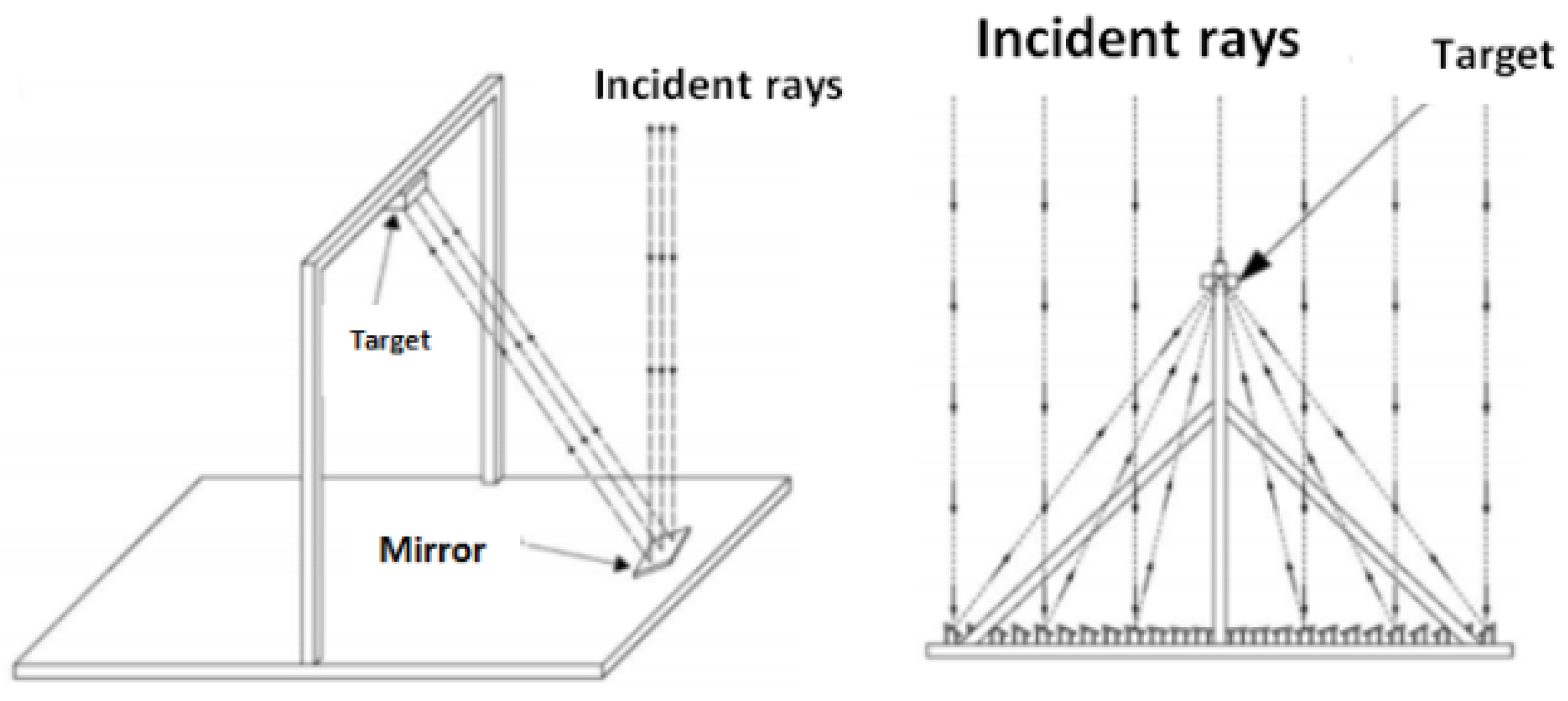
3.2. Parabolic Mirror

The Parabolic mirrors are often used either to produce beams of parallel light or to collect the light coming from a distant source and to concentrate it at a desired point. A parabolic mirror is defined by its depth d, diameter D and focal distance f, as shown in Figure 14.
Jorgensen and Wendelin [21] designed a moulded parabolic concentrator able to produce a uniform flux distribution on a flat surface of several inches per square. This concentrator was formed from five concentric annular sections. Each section was disposed along the optical axis and specified as being a spherical element with a curvature of 1/2f and representing 20% (1/5) of the total area of the openings, as illustrated in Figure 15. Concentration levels of 100 to 200 Suns could be directly achieved for a collection opening corresponding to a diameter of about 1.5 m . This result did not stand for long since Canavarro et al. [22] showed that a parabolic mirror (without secondary optics) remains suitable only at low concentrations of about 70 × with a maximum optical efficiency of around 80%. In more than this concentration range, all the characteristics including the irradiance distribution, the acceptance angle and the optical efficiency start dropping off. This design has a strong dependence on optical tolerance in addition to solar tracking uncertainties and manufacturing accuracy.
Chong et al. [23] designed a planar concentrator, based on non-imaging mirrors. This design consists of many flat squared mirrors of 40 m m × 40 m m to collect and focus the Sun’s rays onto a target surface, as shown in Figure 16. The authors found that the concentration ratio is proportional to the focal length, while the illumination spot size decreases if the focal length increases. In fact, the rise of the focal length from 50 to 100 c m leads to a concentration elevation from 270 × to 310 × , while the illuminated area decreases from 13.43 c m 2 to 10.24 c m 2 . Wang et al. [24] also proposed a mirror based solar concentrator to develop a CPV system with high concentration uniformity. It was based on Linear Fresnel Reflectors (LFR) of different widths. The performances of the new design were compared with those of a hollow parabolic mirror with the same geometric concentration of 31.31×. Simulation results showed that the uniformity of the flux density produced by the LFR is better than that produced by the parabolic trough concentrator (see Figure 17). The optical efficiency reached 62 % with an acceptance angle of 1 .
Yazdanifard et al. [25] modelled and simulated a cylindro-parabolic concentrator for a CPV/thermal system (Figure 18) with an aperture area of 1.95 m 2 and a concentration ratio of 16.92 × ; besides the effects of various geometrical parameters, including the concentration ratio, the system performance was compared to those of a flat-plate Photovoltaic/Thermal (PV/T) system, which has the following dimensions: a length of 1.5 m , a height of 0.09 m and 0.12 m in width. As a result, the CPV/T system exhibits better energy efficiency, which reaches 10.63% of the electrical efficiency determined by Equation (5), compared to the 7.12% of the equivalent CPV/T system. In terms of the ratio of efficiency to the PV area and the cost of the PV cells, the CPV/T can be considered as exhibiting better performance potential when compared to the PV/T system.
η e l e c = P V o u t p u t p o w e r P p u m p p o w e r beam   radiation   intensity × a r e a

3.3. Compound Parabolic Concentrator

Several authors have studied the Compound Parabolic Concentrator (CPC), since it is considered to be the optical element that gives the best concentration performance by approaching the thermodynamic limit. The CPC (Figure 19) is defined by its geometrical parameters related by the following equation, simply obtained by using the Snell–Descartes laws for refraction and the outside angles of this optical element:
a = n r sin θ a c c
L = ( a + r ) cot θ a c c
f = r ( sin θ o u t + sin θ a c c ) n
θ a c c = 2 arccos 1 n θ o u t
where a is the input radius of the CPC, r is the exit radius of the CPC, L is the CPC length, θ a c c and θ a c c are respectively the external and internal acceptance angle and θ o u t and θ o u t are the external and internal output angle of CPC, respectively. Starting from the well known point of view that the exit angle of the CPC is not restricted (exit angle = 90 ), Yu et al. [26] investigated and compared both theoretically and experimentally the performances of a CPC without restriction (exit angle = 90 ) and with a restricted exit angle (exit angle of 65 ) designed with several acceptance angles. The dimensions of the CPCs used are summarized in Table 1 in the case of an acceptance angle of 20 . Their results show that if the acceptance angle is larger than 20 , the optical efficiency of the C P C 90 is higher than that of the C P C 65 ; however, for angles smaller than or equal to 20 , the optical efficiencies are identical ( ± 92 % ) for the two shapes. The experimental results confirm this similarity of performances with 21.71 W and 21.29 W respectively for C P C 65 and C P C 90 .
Timinger et al. [27] studied the optimization of a faceted CPC (three to 24 facets), as shown in Figure 20a. They compared their performance at the level of concentration. Their results show that CPC performance increases with the number of facets. Indeed, for a CPC acceptance angle of 30 , the authors reported an optical efficiency of 95% for 24 facets and 85% for three facets. Van Dijk et al. (vanDijk, 2015) confirmed these results. The circular CPC (number of infinite facets) can achieve an optical efficiency of 100% for low concentrations (<10×). Regarding the uniformity of the flux distribution at the output of these elements, Cooper et al. [28] showed that the flux is more uniform with an elevated number of in the facets (see Figure 20b), which makes the element closer to a circular form.
Another CPC configuration is a 3D CPCs filled with a dielectric with a total internal reflection as reported by Winston [30]. In this case, according to the refraction law, taking into account the refractive index for the dielectric medium, the maximum output and input acceptance angle (see Figure 21) are intimately related and are plotted in Figure 21, as a function of the refractive index of the medium. It is then clear that for a positive incidence angle, the minimal refractive index needed is 1.12 and that the high index refraction for a 90 incidence angle is 1.6, which is the extreme limit ensuring that an incoming ray goes out of the CPC. El Himer et al. [31] also studied the performance of the optical and geometrical properties of a filled compound parabolic concentrator. The results show that this element can achieve a 95% optical efficiency, but it presents a huge non-uniformity of the output flux distribution.
Baig et al. [32] tested the optical performance of a refractive CPC on a 1 c m × 1 c m solar cell. They reported that the optical efficiency reached 73.4%, but that the flux distribution is not uniform on the cell. Su et al. [33] proposed a lens-walled CPC (Figure 22), considered as another kind of CPC. The lens shape was formed by internally rotating the parabolic curves of a CPC by a small degree around the top end points of the curves. The refraction of the lens allows the lens-walled CPC to concentrate light from wider incidence angles. This type was compared with a solid CPC and mirror CPC. As simulation results, the authors found that the lens-walled CPC and mirror reach 85% optical efficiency, and the solid CPC presents 90%; however, the lens-walled CPC presents a wider angular tolerance, which arrives at 35 , compared to the other two types, which reach only 25 .
More recently, Siti Hawa et al. [35] presented a new asymmetric CPC design dedicated to low concentration systems. It is known as the Rotating Asymmetric Compound Parabolic Concentrator (RACPC). The simulations and indoor test show that for a CPC with an acceptance angle of 45 , the optical efficiency reaches 90% by simulation and 84% by experimental tests for a normal angle of incidence ( 0 ). These values drop below 10% when the ray incidence angle is ± 50 . Outside this angle, the optical efficiency drops to 0%. However, the achieved concentration ratio is around 3.01 × .
The refractive CPC presented by El himer et al. [31] allows having a high optical efficiency, which reaches 95% with a wide acceptance angle (45%), but it presents a non-uniform light flow on the cell, as well as the low concentration due to its small size.

3.4. Hyperbolic Concentrator

The hyperbolic concentrator is mostly used for thermal application more than photovoltaic ones. Sellami et al. [36] designed and created a Square Elliptical Hyperboloid Concentrator (SEHC) for photovoltaic applications. For an SEHC of a concentration of 4 × , the results show a constant optical efficiency of 40% with a large acceptance angle of 120 , within which this configuration allows the collection of both diffuse and direct radiation all day. A 70% high optical efficiency is obtained for different dimensions of the SEH concentrator; however, the acceptance angle is still only around 50 . The SHEC is considered as filled with a dielectric material and operating in total internal reflection. It can capture the Sun’s rays throughout the day.
Imhamed et al. [37] also presented a study on the design of a three-dimensional solar Elliptical Hyperboloid Concentrator (EHC). Their design (see Figure 23) was based on the following Equations (10)–(13) [37]. The coordinates of the profiles connecting the ends of the major axis, A and a, and the minor axis, B and b, are given by:
Y 1 = ( ( x a ) 2 1 ) H 2 ( C R 1 ) 1
C R = ( A a ) 2
Y 2 = ( ( x b ) 2 1 ) H 2 ( C R 1 ) 1
C R = ( B b ) 2
It was found that the effective concentration for the 3D EHC increases with increasing the height of the concentrator. The optical efficiency varies as the shape changes from a circular profile to an elliptical profile with a different (a/b) aspect ratio. For the EHC, the optical efficiency is two times higher than that produced by circular profile for an optimal form factor (a/b) equal to five. In the case of an acceptance angle of 30 , the calculated height of the hyperbolic concentrator is 0.4 m, and the optical efficiency is 27%, while the concentration ratio is 20 × .

3.5. Conical Concentrator

Williamson [38] and Kloiber et al. [39] analysed a cone shaped concentrator. This shape is considered as an ensemble of sections delimited by the reflection points (see Figure 24). The total length is then calculated as follows:
x = k = 0 2 n p k
with
p n = ( t k = 0 2 n p k ) tan γ tan γ + tan ( Φ 0 + ( 2 n + 2 ) γ )
and the input radius is
a = t tan γ
with:
  • γ  the cone angle
  • Φ0  the aperture angle
  • pk  the projections of the kth path of the ray on the optical axis
  • n  number of reflections
  • x  length of a cone
  • t  cone height
Inside a cone with a certain length, a Sun ray can undergo a number of reflections n, and it deviates at each one of them by an angle equal to twice the cone angle γ ; this makes it possible to design a cone by considering the number of reflections inside it, given by:
n 90 Φ 0 2 γ
Williamson’s analysis was only restricted to parallel rays, which unfortunately gave a very optimistic estimate of the concentration by simulations; they obtained an optical efficiency of about 85%, and experimental measurement gave a value of 75%. Concerning the flux uniformity, they showed that the concentrated flux has a very high peak at the centre of the cone output.
Kiatgamolchai and Chamni [40] developed the two-dimensional cone concentrator theory, designed to be parallel to Sun rays (Figure 25). As the cone lengthens, the number of internal reflections increases, and the ratio between the inlet and outlet aperture also increases, resulting in a high concentration ratio C g . This proves the direct relationship between the number of reflections and the concentration ratio. Moreover, the number of reflections in the cone can be the main parameter for designing and sizing a given cone, in a way that if it increases, the height of the prism and also the Cg increase. A concentration system using a simple cone was able to reach an efficiency of 27% [40].

3.6. Luminescent Concentrator

A Luminescent Solar Concentrator (LSC) consists of thin transparent layers made of plastic or glass that contain a fluorescent dye or phosphors. As shown in Figure 26, when the incident rays (1) reach the top surface, some rays are reflected due to Fresnel loss (2) and some are transmitted into the waveguide. A part of the transmitted ray will just escape from the bottom surface of the waveguide without being absorbed (4) because of the limited absorption range of the dyes. The others will be absorbed by dyes (3) and emitted in lower energy. Therefore, when the incident angle is larger than the critical angle, they will be reflected by TIR in the waveguide (6) and finally hit the cell (8). When the angle is smaller than the critical angle, the ray will escape from the waveguide (7). However, some fluorescence will hit the fluorophore modules again during the propagation and get re-absorbed (5,6) if the absorption spectrum overlaps the emission. Fluorescence can also be absorbed and lost by the host material (10). Finally, due to limited emission quantum yield (9), some of the absorbed photons are not re-emitted, but instead lost as heat and vibration.
The advantage of a Luminescent Solar Concentrator (LSC) is that it can work without the need for Normal Direct Irradiation (DNI), tracking and large sizes. Batchelder et al. [42] were the first authors who used a laser dye solution between two sheets of glass with an emphasis on planar geometry, and they found that for a CPV system with a geometrical concentration of 100 × , the total solar spectrum conversion efficiencies are 18% and 21% for silicon and gallium arsenide cells, respectively. Silicon utilizes about = 64% of the spectrum, while gallium arsenide uses about 42%. Comparing those results to other CPV systems, we found that this kind of concentrator has a low efficiency because of the losses cited above. Micic et al. [43] showed in their research that luminescent concentrators are able to absorb light over an extremely wide wavelength range and that the absorption spectrum also describes the spectral shift towards higher energy as the size of the luminescent concentrator decreases. The major advantages of these concentrators are as follows: they are devoid of any Sun tracking system; they can concentrate diffuse and direct radiation [44]; because of their geometry, they have less heat dissipation problems [44]; and the metal layers are inexpensive. Gallagher et al. [45] studied three luminescent concentrators and performed a comparative analysis to determine the concentration ratios for the different types. A Maximum Concentration Comparative Factor (MCCF) was determined at specific solar intensities using the following Equation (18):
M C C F = P ( d e v m a x ) P ( r e f m a x )
where P ( d e v m a x ) is the maximum power for the test device and P ( r e f m a x ) is the maximum power for the reference devices. The manufactured concentrator system was compared to two reference samples: (A) a polyurethane sample (without Quantum Dots (QD)) cast in a mirrored perspex mould; (B) a polyurethane sample cast in an unmirrored perspex mould; the PV cell orientated as in a QDSC (Quantum Dot Solar Concentrator) poured into a mirror plexiglass mould; the PV cell oriented as in a QDSC. The device tests were (1) a module of 11.5 c m × 11.5 c m × 0.3 c m made of polyurethane and CdSe/CdS QDs and (2) a module of 5 c m × 5 c m × 0.3 c m made of polyurethane and CdSe/CdS QDs. As a result, the MCCFs found are listed in Table 2:
Several other authors have introduced the luminescent concentrator with several sizes. For example, Gutierrez et al. [46] demonstrated and tested the feasibility of LSC by the use of carriers transferred between two π -conjugated polymers (poly(arylene ethynylene)s) and a judicious selection of a minority red emitter (perylene bisimide Lumogen F Red 305). They tested a prototype of 1.75 × 1.75 × 0.15 c m 3 with an optical efficiency of 40 % and reported that this efficiency decreases with higher geometrical sizes. Nanotechnology has also entered this field of solar concentrators; for instance, Meinardi et al. [47], benefiting from highly emissive silicon quantum dots, modelled and developed a rather large-scale semi-transparent LSC with dimensions of 12 × 12 × 0.26 c m 3 . The host material was the poly(lauryl methacrylate) in which the indirect bandgap silicon quantum dots were embedded. Their LSC achieves an optical efficiency of 2.85 % . In the same way, Mateen et al. [48] presented a nitrogen-doped carbon quantum dots based waveguide coupled to a polymer dispersed liquid crystal to manage an LSC to modulate the transmission of visible and near-IR light. Their LSC is 50 mm × 25 mm × 4.2 mm in size and reaches an optical efficiency of 4.52%.
To summarize, we presented in this section all the CPV concentrators that use one optical element. We note that a one stage optical element for CPV systems cannot achieve the overall performance criteria of a CPV system; either the system has a high efficiency while the flux distribution is not homogeneous on the cell, or the opposite. In Table 3, we summarize the maximum optical efficiency achieved by each optical element and its acceptance angle.

4. Multistage Concentrators

Multistage concentrators are concentration systems that use two or more optical elements. The first stage is named the Primary Optical Element (POE), and the second is the Secondary optical Element (SOE). The latter has to be designed in order to catch the light issued from the primary whatever the Sun position [49,50].

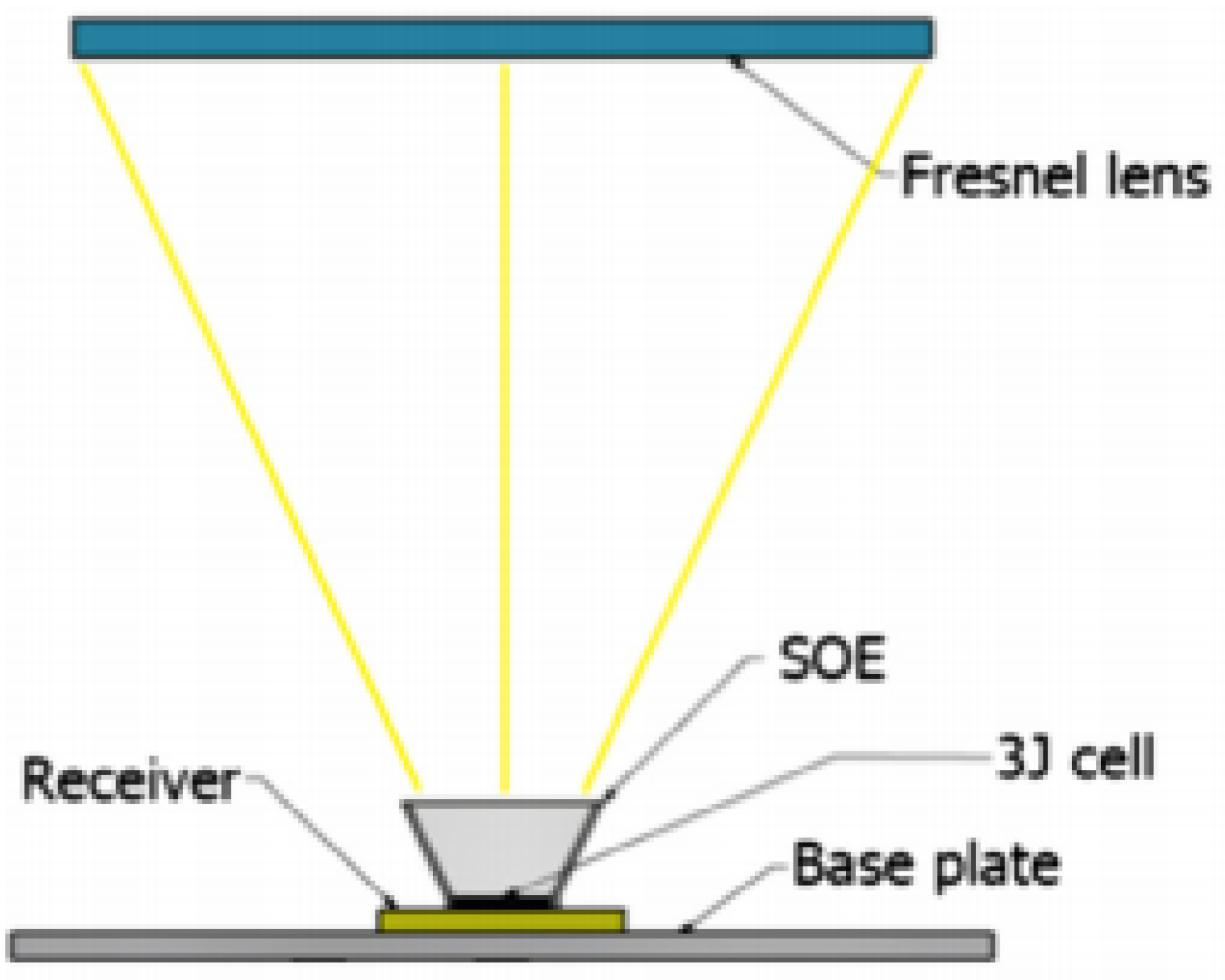
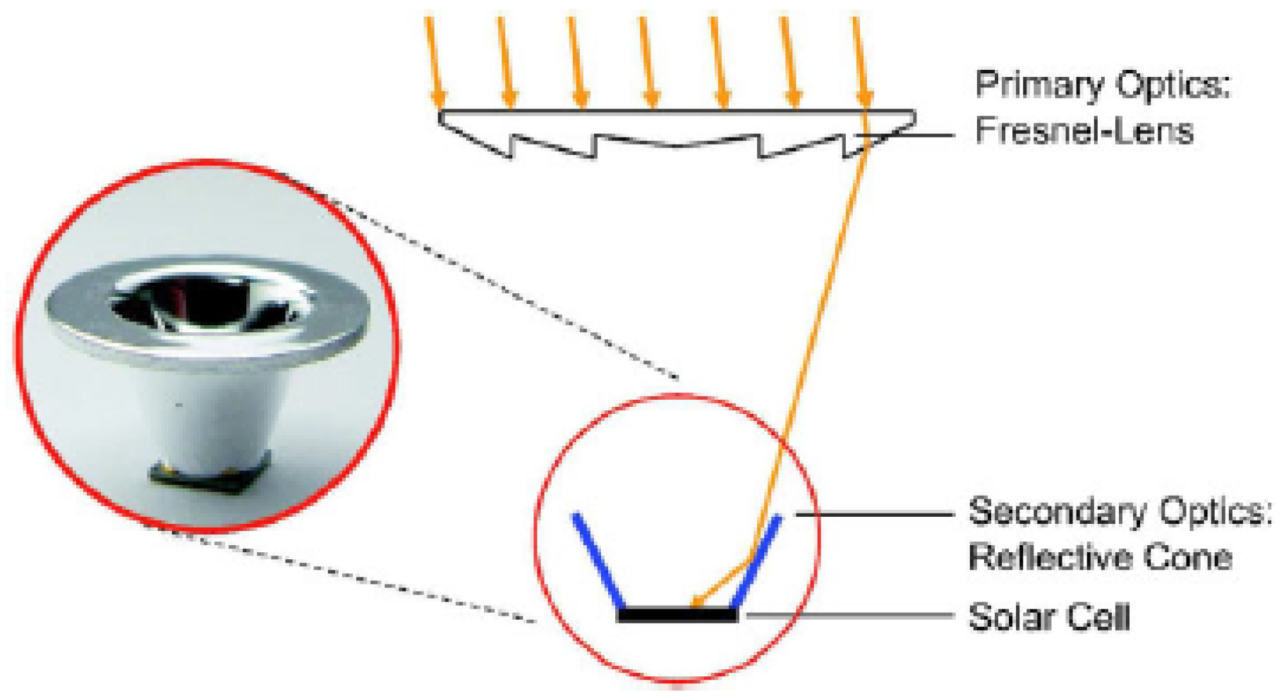
4.1. Concentrators Based on Fresnel Lenses as a Primary Element

Shanks et al. [3] proposed a CPV system consisting of three optical elements and one solar cell (Figure 27) for a concentration ratio of 3000 × . The primary optical element consists of four Fresnel lenses, each one having 210 × 210 m m 2 ; their total diameter is 420 × 420 m m 2 , and the focal length is 320 m m . The secondary is formed from four planar mirrors, while the third element is a planecentral mirror. The total height of the system is 460 m m . This concentrator has an optical efficiency of 55% with an acceptance angle of 0 . 4 . Regarding the uniformity of the concentrated flux, the results show a high intensity at the centre of the cell and a rather weak one at its ends. Rodríguez et al. [51,52] studied, by simulation and experimentally, four HCPV concentrators composed of a Fresnel lens and four secondary elements (CCPC, pyramid, hyperbola and dome). All elements are made from PMMA for a targeted concentration ratio of 1000 × . The lens is a square of 130 m m sides, 1 m m thick and a focal length of 152 m m . Simulation results show that the four concentrators have an optical efficiency greater than 80% and an acceptance angle of ± 1 . The best homogeneity of the flux is obtained with the pyramid. Experimental tests validated these results with a fall of the optical efficiency to 73% and the angle of acceptance to ± 0 . 8 . These systems seem easier to manufacture than the three stage one, and a rather good comparison between simulation and experiment can be noticed.
A similar study was performed by El himer et al. [49] who compared only by simulation and analysed four CPV systems based on four secondary optical elements (CPC, CCPC, cone and pyramid) associated with a circular flat Fresnel lens made from PMMA with a diameter of 350 mm and a focal length of 265 m m for a concentration ratio of 1000 × . The SOEs are the same length (48.30 m m ) and the same output diameter (10 m m ); however, the input diameter of the CPC/CCPC is 27.58 m m , and the cone/pyramid is 15.05 m m . They also confirmed that the pyramid as the SOE presents the most uniform illumination on the solar cell, the largest acceptance angle ( 1 . 4 ) and the highest optical efficiency (83%) whatever the material used. The use of pyramid as an SOE was also investigated by Renzi et al. [53] where it was associated with a Fresnel lens with an aperture of 75 m m × 75 m m , a focal length of 128 m m and a constant pitch of 1 m m (Figure 28) for a concentration ratio of 1300 × . The pyramid was manufactured from B270 glass with an input aperture of 6 m m , and they used a multijunction solar cell of 4.15 m m 2 . The results show that this design has the capacity to achieve an electrical efficiency of 39.55% and an optical efficiency of 78.38%. A similar parametric theoretical study was reported by El Yahyaoui et al. [54]. They studied a concentrator design consisting of an inverted truncated pyramid, used as the secondary, with a Fresnel lens as the primary optics to improve the performance of the CPV module with a concentration ratio of 1000 × . The output of the system deals with a solar cell of 10 × 10 m m 2 . The inclination angle and height are optimized to achieve high values of optical efficiency and acceptance angles. Different pyramids with heights from 15 to 28 m m were evaluated by ray-tracing simulation, using the same Fresnel lens with a diameter of 350 m m , made from PMMA. For a fused silica-made pyramid, the authors found that the highest optical efficiency (87,524%), as well as the good acceptance angle θ 80 % = 0 , 96 are obtained with a concentrator height of 28 m m and an inclination of 16 . These results are for now under test in real conditions.
Winston and Ritschel [55] patented an optical concentrator. It consists of a primary Fresnel lens and a Dielectric Total Internal Reflection Concentrator (DTIRC) as a non-imaging secondary optics to concentrate a high solar flux on the solar cell. The primary Fresnel lens has a f # greater than one, and the solar cell is stuck on the opening of the output of the secondary concentrator. The optical concentrator has an optical acceptance angle of about ± 0 . 5 and a theoretical optical efficiency between 80% and 85%.
Jaus et al. [56] studied a 40 × 40 m m 2 square shaped Fresnel lens with a focal length of 76 m m . This lens is associated with a reflective aluminium cone. The diameter of the solar cell is 2 m m , which gives a calculated geometric concentration factor of 302 × . This system can achieve an electrical efficiency of 29.1% (see Figure 29).
Xu et al. [57] did experimental tests on an HCPV/T system (High Concentrator Photovoltaic/Thermal), which is a hybrid system that can produce both electricity and heat to increase the overall efficiency composed of a Fresnel lens with a surface of 330.2 × 330.2 m m 2 , which is associated with an optical prism (pyramid) and solar cell of 10 m m 2 (Figure 30). The concentrator has a geometrical concentration of 1090 × . Experimental results show that this system has an instantaneous electric efficiency of 28% and an optical efficiency of 87%.
Chen and Chiang [58] proposed a comparative study to determine the optimal SOE parameters. For this, a Fresnel lens was associated with three types of SOE, including a kaleidoscope with an equal optical path design, a filled pyramid, and an open truncated pyramid. The Fresnel lens size is 40 m m × 40 m m , and the size of the solar cell, used for the three systems, is 1.25 m m × 1.25 m m , resulting in a geometric concentration ratio of 1024 × . The SOEs were all made of BK7. The simulation results show that the kaleidoscope is the best SOE. It has the highest acceptance angle of 1 . 7 , as well as good optical efficiency (85%). Nevertheless, the truncated pyramid presents a better distribution of the irradiance on the solar cell with a lower acceptance angle of ( 0 . 3 ).
Ferrer-Rodríguez et al. [59] proposed a High Concentration Photovoltaic (HCPV) system based on a Fresnel lens. Two basic SOE designs were modelled and optically simulated: the dome kaleidoscope with the fracture symmetry vertex and the SILO (SIngle-Lens Optical element). The Fresnel lens is made of PMMA with an area of 100 × 100 m m 2 and a focal length of 162 m m . The secondary ones are both made of fused silica. The kaleidoscope has a height of 21 m m , an inlet area of 12 × 12 m m 2 and a square outlet area of 4 × 4 m m 2 . The SILO has a total height of 9.9 m m . Simulations show that the dome kaleidoscope has the best performance with an optical efficiency of 86.5%, an acceptance angle of 1 . 4 and a uniform flux distribution compared to the performance of the SILO, presenting an efficiency of 80.6% and an angle of 0 . 71 .
Limin Guo et al. [60] proposed to add a secondary focusable microprism between the Fresnel lens and the solar cells (see Figure 31) to improve the optical efficiency and improve the tracking accuracy against the vibration of the structure induced by the wind. The solar cell area is 2.5 × 2.5 m m 2 ; the area of the silicon on glass-made Fresnel lens is 50 × 50 m m 2 ; and its focus is 93.5 m m . The concentration ratio is set to 400 × . The height of the secondary is fixed at 2.15 m m with the upper spherical diameter of the microprism of 18 m m . The experimental results correspond fairly well to the simulation results. The optical efficiency obtained is 88.67% with an acceptance angle of 1 . 2 and electric power of 144.7 W .
Qilu Huang et al. [61,62] studied and tested a novel CPV optical system with a truncated spherical lens as a secondary optical element to reduce the cost of the receiver assembly and improve its long-term reliability, as illustrated in Figure 32. The POE is a Fresnel lens made from silicon on glass with an area of 50 × 50 m m and a focal length of 84 m m . The geometric concentration of the system is 625 Suns. The truncated ball lens is a glass ball lens with a flat bottom surface for assembly of the receiver, and it is made of glass (n = 1.51) with an anti-reflection coating. The simulations show that the optical efficiency reaches 95% with an acceptance angle of 0 . 7 . Regarding the flow distribution, it is found to be almost very uniform, and this uniform spatial irradiance is preserved for the entire solar spectrum. The experimental tests show an efficiency of 30.3% with a fill-factor of 83.3% and an acceptance angle of 0 . 72 (which is almost equal to the value of the simulation) for a cell temperature of 25 C and a DNI of 815 W / m 2 .
From this literature review, as illustrated in the Table 4, we can say that there are several parameters that need to be regarded to choose this or that element as an SOE associated with a Fresnel lens like a POE. The larger acceptance angle is for the mirror kaleidoscope, but the highest optical efficiency is presented by the pyramid. The latter also shows the most uniform flux distribution on the solar cell. At this stage, the pyramid appears as the most suitable secondary element with a Fresnel lens like a POE.

4.2. Concentrators Based on an Aspheric Lens as the Primary Element

Victoria et al. [63] studied the optical performance of the four secondary elements (cone, pyramid, CPC and domed lens) associated with an aspheric lens. These performances are compared in terms of optical efficiency, acceptance angle and flux uniformity for a concentration ratio of 1000 × . The cone and the pyramid have a length of 7 m m and an input diameter of 9 m m . The CPC has a length of 16 m m and a diameter of 8 m m . The length of the dome is 5 m m . Simulations of these systems show that the optical efficiencies reach 89% for the cone, 88% for the pyramid, 87% for the CPC and 86% for the dome. However, the acceptance angle was small and reached only ± 0 . 52 for the cone and ± 0 . 94 for the pyramid, but it reaches ± 1 . 4 for the CPC. Concerning the uniformity, the pyramid and the dome have the best uniformity in the flux distribution compared to the cone and the CPC. We can see that in the case of the aspheric lens as the POE and the use of the cone as the SOE, a higher optical efficiency (89%) compared to the CPC (87%) is achieved, and this seems to be the first time where the cone overtakes the CPC compared to the reported results in the literature (El Himer et al. [49] and Rodriguez et al. [51]).
The aspheric lens is rarely used as a primary optical element in CPV systems, even if makes it possible to have a high optical efficiency, but the angle of acceptance is small compared to the use of the Fresnel lens, as reported in Table 4.

4.3. Concentrators Based on a Parabolic Mirror as the Primary Element

Several authors have discussed the performance of parabolic mirrors either as a primary optical element or as a secondary element. Ries et al. [64] proposed and analysed a two stage photovoltaic concentrator consisting of a large aperture dish as a primary optical element and a flux homogenizer, which is a kaleidoscope mirror, as the secondary. The authors adapted this secondary element concept to photovoltaic concentrators where the required flux is typically at least one order of magnitude lower than the average concentration in the focus of the dish. Their proposal was to place the secondary out of the focal plane, away from the dish, as shown in Figure 33a. This concentrator is designed to have a concentration of 500 × and has been successful in improving the flux distribution at the secondary exit, as shown in Figure 33b.
Feuermann and Gordon [65] proposed a CPV where the light is focused on the cell via an optical fibre. The system is based on a parabolic mirror with a diameter of 130 m m and a focal length of 121 m m , as well as a plane mirror and an optical fibre to reach 1000 Suns (Figure 34); the length of the optical fibre is 120 m m , and the optical system is associated with a solar cell of 9 m m 2 . With these dimensions, this design achieves an optical efficiency of 85%.
Yew et al. [66] designed a concentration system consisting of a parabolic mirror as the primary optics and a set of crossed compound parabolic concentrators with a rectangular section as the secondary optics (Figure 35a). The primary has a surface area of 226 m m × 226 m m and a focal length of 186 m m , while the secondary element is a matrix of 8 × 8 of CCPCs, each of them having a geometric concentration ratio of 5.99 × . The system is used with a solar cell of 9.58 m m × 9.58 m m . This choice is made so that the total surface (195.5 m m × 195.5 m m ) of the entry opening of the CCPCs can correspond to the focused image of the primary. The simulation results show that the achieved optical efficiency is 77%, and the flux distribution is more homogeneous, as shown in Figure 35b. However, the experimental results reported by Chong et al. [67] showed that the power conversion efficiency of this system is only 17%, and the system shows [68] a uniform illumination on the solar cell; concerning the concentration ratio, it reached 88 × . Comparing the performance of this secondary element with the mirror and with the Fresnel lens, we notice that the CCPC is more efficient if we associate it with the Fresnel lens in terms of optical efficiency (83%) compared to the mirror (77%).
Steinfeld [69] compared the performance of a reflector cone with a CPC, when used as secondary optical elements associated with a primary dish. The author showed that, for a low concentration, the cone allows having a high optical efficiency (91%) compared to the CPC, but becomes inefficient for higher concentrations; this was the same remark in the case of the Fresnel lens as a primary optical element (CPC: 82.3%, cone 78.3% for 1000 × ).
Zhang et al. [70] investigated five solar concentrators based on a parabolic mirror as the primary optical element; the secondary ones were: a flat mirror (a), ellipsoidal mirror (b), upper hyperboloidal mirror (c), lower hyperboloidal mirror (d) and paraboloidal mirror (e), as shown in Figure 36. They analysed and compared their concentration ratios by varying the rim angle from 30 to 120 . The simulation results show that when using a flat mirror and while varying the rim angle from 30 to 90 , the concentration ratio increases until it reaches a maximum ( 200 × ) in about 60 ; beyond this angle, the flux concentration decreases towards 10 × . Using the lower hyperboloidal mirror as the secondary optics, the concentration reaches a maximum value ( 160 × ) for a rim angle of 0 and decreases by increasing the rim angle. Concerning the case of an upper hyperboloidal mirror and ellipsoidal mirror as the secondary ones, the concentration ratios are almost equal and stable ( 100 × ) by varying the rim angle from 0 to 80 ; beyond this value, the concentration drops sharply towards 0 × for the ellipsoidal mirror and slightly for the case of the upper hyperboloidal mirror. For the last case, which is the paraboloidal mirror as the secondary optics, the concentration ratio is low and stable ( 10 × ). The case of the flat mirror and the lower hyperboloidal mirror as the secondary ones is more sensitive to the rim angle and has high concentrations, but their angular tolerances are low, while the upper hyperboloidal mirror and ellipsoidal mirror have stable performances.
Chen et al. [68] designed a two mirror two stage concentrator, as shown in Figure 37, the primary having f # of 0.22, and the secondary has a numerical aperture of 60 . The results show that the concentration ratio increases with the increment of the Numerical Aperture (NA) defined as N A = n sin θ with n the refractive index in the observation medium and θ the angle between the optical axis and the furthest ray, from the optical axis, entering the lens. The concentration was reported as decreasing from 2000 × for a normal incidence ( 0 ) to 400 × for 0 . 2 . However, the spot size increases with the NA, and it was reported to be 8 m m for an NA of 0 . 6 and increases respectively to 10 m m and 24 m m for 0 . 5 and 0 . 2 .
Brunotte et al. [71] presented a two stage concentrator approaching a concentration level of 300 × . This concentrator consists of a hollow dish as the primary optical element and a CCPC as the secondary optics. This concentrator could have an optical efficiency of 77.5%, and a concentration of 231 × was obtained. The association of the CCPC as the SOE with a dish mirror [66] or a hollow dish [71] has the same optical efficiency (77%).
Chen et al. [72] studied the performance of an optical system composed of a parabolic mirror as the POE, a flat mirror and a pyramid (see Figure 38). The study was made by comparing three design phases: the first was with a refractive pyramid with a height of 13 m m , the second with a refractive pyramid with a 15 m m height and the last with a reflective cone. Simulation results show that the optical efficiency reaches 84.24%, 82.834% and 82% respectively for the 1 m m and 15 m m pyramids and the reflective cone. Regarding, the acceptance angle, it is found to be wider for the reflective cone ( 1 . 6 ) and 1 . 03 for the two refractive pyramids. The pyramid allows having a high optical efficiency and a wide acceptance angle whatever the primary optics (Fresnel lens, aspheric lens or a mirror).
Lokeswaran et al. [73] designed a CPV system based on a square parabolic mirror as a primary optical element and a reflective secondary concentrator (CCPC) to homogenize the distribution of the flux on the cell (Figure 39). The primary optical element has an aperture area of 9 m 2 , and the matrix ( 12 × 12 ) of reflective crossed compound parabolic concentrator has a surface of 0.27 × 0.27 m 2 . For an optimized homogenizer length of 5 m m and a height of 3700 m m , the system could have an optical efficiency of 68.30%; in contrast, a very homogeneous flux distribution was obtained, as shown in Figure 40. The combination of the reflective CCPC as the secondary and the square parabolic mirror provide the highest homogeneity distribution so far.
Trespidi et al. [74,75] described the optical design of a new mirror based solar concentrator operating with an off-axis configuration, as shown in Figure 41. The Primary Optical Element (POE) is an off-axis reflecting paraboloid that focuses the collected light beam onto a secondary optical element (SOE), which fills the pyramid. The focal length of the mirror is 60 mm with an area of 18 c m × 35 c m . The geometric concentration of the CPV system is 850 Suns. The optical system exhibits an optical efficiency of 83% and an acceptance angle of ± 0 . 5 .
Ferrer-Rodríguez et al. [76] analysed a two stage CPV system; the primary consists of four optical units based on Cassegrain, which concentrate sunlight towards a hyperboloid mirror as a Secondary Optical Element (SOE), the geometric concentration of this system is 2000 × . The diagonal of the primary is 173.9 m m , and the focal length is varied from 90 to 230 m m . Optical efficiency is stable at 84% for a focal length of 90 to 110 m m , but beyond this value, the efficiency decreases to 77%. The acceptance angle increases until it reaches its maximum of 0 . 44 for a focal length of 110 m m ; thereafter, it decreases to 0 . 23 . The use of the parabolic mirror as a primary optical element shows interesting optical performances especially if it is associated with a flat mirror since it presents the best achieved optical efficiency of 85%, as is shown in Table 5, which summarizes the optical systems based on a parabolic mirror.
According to our bibliography, we plotted a figure of merit to make an easy comparison between all these optics systems. It is shown in Figure 35 and is designed taking into account the main characteristics: effective concentration ratio, flux homogeneity, acceptance angle, geometrical concentration and the cost. The maximal value of each parameter is used to normalise the others. For homogeneity, we just scaled from the best to the worst case. We can conclude that the CPV system is more efficient if we use two optical elements of concentration, since this allows having an optical efficiency and a high concentration, as well as a wide acceptance angle, as shown in Figure 42. Finally, the pyramid is the most suitable element as the SOE whatever the primary element and is better with a Fresnel lens since it has an efficiency of 83% and 1 . 4 as the acceptance angle.

5. Current Performance of CPV Systems

5.1. Module Efficiency of Industrialized CPV Modules

In recent years, various commercial modules of the HCPV have been proposed with several performances and features. It should be noted that the module efficiency data correspond to the standard test conditions: temperature 25 and DNI = 1000 W / m 2 .
From the data of the HCPV modules found in the market, it can be noted that compared to the values of the concentration ratio, the average is 833 × , with 40% of the HCPV modules having higher concentrations. The median is 810 × .
Six HCPV modules operate with a higher level concentration than 1000 × : Arima, Emcore, Semprius, Soliant, Suncore and Abengoa with a concentration of 1300 × . They represent the single case where a much higher concentration ratio has been reported. However, there are some examples of a concentration ratio around 500 × (Isofoton, Redsolar, Soitec and Solfocus).
In terms of optics, many concentrator concepts are based on Fresnel lenses associated with secondary optics. Mirror based designs are also available on the market, as in the case of Solfocus, but operating at a relatively lower concentration ratio ( 650 × ). Other less-common designs, such as the dome shaped Fresnel lens or light guides (Sun Simba TM from Morgan Solar; Daido) are also used.
Finally, the electrical efficiencies values of the available modules indicate an average of 30% and range from a minimum of 25% (MagPower) to a maximum of 34% (Arima). Seven different manufacturers among all the analysed HCPV modules guarantee providing HCPV modules with efficiencies greater than 30% (Abengoa, Amonix, Arima, Redsolar, Semprius, Soitec and Suncore) [8].
Most of the top five commercial modules (Abengoa, Amonix, Arima, Redsolar and Semprius) use Fresnel lenses as a primary optical element; the only exception is Semprius modules, which use small plano-convex lenses. Regarding the type of solar cells used, all these HCPV modules incorporate multi-junction solar cells. As far as the manufacturers of the best performing modules are concerned, two are American (Amonix and Semprius) and two are Asian (Arima in Taiwan and Redsolar in China), and Abengoa is European (Spain).
In Figure 43, the values of the efficiency of the commercial modules are plotted as a function of their geometrical concentrations. In the case of the modules, the points in the upper right zone, that is to say more than 1000 × in geometric concentration and above 30% of the efficiency of the module, correspond to the most competitive designs.

5.2. Acceptance Angle

The values of the acceptance angles of the considered HCPV modules range from ± 0 . 4 (Soitec) to ± 1 . 9 (MagPower), although they are generally in the range ± 0 . 7 to ± 1 (Arima, Emcore, Semprius, Solfocus and Suncore), with an average of about ± 0 . 9 and a median of ± 0 . 8 . Figure 44 shows the current values of the acceptance angle of the commercial modules with respect to the geometric concentration. Most values of the acceptance angles are between ± 0 . 7 and ± 1 and are distributed relatively uniformly with respect to the geometric concentration values. As already mentioned, the HCPV modules with the best optical systems have the highest concentration and the largest acceptance angle. Figure 44 shows that the maximum value of the acceptance angle ( ± 1 . 9 ) corresponds to a HCPV module with an average geometric concentration ratio of 800 × , while the HCPV module with the highest concentration ( 1300 × ) has an acceptance angle value near the average value. This value of ± 1 . 9 reported by MagPower seems to be an exception because all the others are less than 1 . 1 .
Despite their high efficiency, the CPVs still suffer from a lack of demand and investor involvement, which implies their failure in the commercial field. Much effort is made and much research done to fix this problem and to balance between the efficiency and cost.

6. New Trends

Different configurations of CPV components result in a wide variety of module designs, resulting in the emergence of novel technologies in this CPV field.

6.1. Micro-CPV

Micro-Concentrator Photovoltaic (MCPV) systems are an unconventional method for developing high-efficiency low-cost PV systems. They have also the potential for installation on rooftops, as well as in cramped spaces, at low cost comparable to flat photovoltaic panels [77]. Micro-CPV systems are based on the miniaturization of the systems’ dimensions (cells and optics).
Based on the same principle as CPV modules, micro-CPV (Micro-CPV) modules simply have smaller dimensions. Typically, the width of an multijunction solar cell. does not exceed one millimetre; the primary optics is a few centimetres per side, of the same order of magnitude as the thickness of the module. Figure 45 shows the main differences between a CPV module and Micro-CPV [78]. In addition to the varying dimensions, the rear face of micro-concentrators is not necessarily equipped with a heat sink. The small collection area of the lenses reduces the amount of heat to be removed. The metal tracks that connect the cells in series are sufficient to dissipate the heat of the cell’s conversion losses [78].
In this approach, as full lenses are used, high optical efficiency can be achieved omitting Fresnel lens losses from draft angles or tip rounding. Furthermore, as the concentration ratio is reduced, the heat input per cell is reduced, resulting in reduced solar cell temperatures, and the thermal management is then facilitated. Finally, due to the low total current per cell, the electrical performance is less sensitive to the non-uniformity of the flux distribution.
This approach provides new and potentially low-cost manufacturing and assembly technologies by easily finding synergies with the fast-paced micro-fabrication and macro-electronic industries producing flexible displays and micro-light-emitting diode (LED) technologies. However, the main challenges are in handling many components with high precision with placement in small spaces and the micrometer range. This actually is required not only during the assembly, but also needs to be maintained during operation where the positions can change due to thermal expansion. Furthermore, we find that several companies have started to use this technology for medium and high concentrations. The micro-CPVs operate with a rate of less than 400 × : Sharp 250 × [79] and IRDEP FR: 73 × [80] have a module efficiency of, respectively, 32.7% and 12.6%. Semprius also has modules with an efficiency of 35.0% [81] and works with a concentration rate of 1111 × . Insight and Morgan Solar companies were able to achieve module efficiency of 36.4% and 29.0% [82], respectively, using micro-concentration.

6.2. Use of Diffuse Irradiation

Until now, CPV technology has used only direct radiation. Thus, the diffuse radiation is lost. In order to capture diffuse radiation, new designs of CPV modules are being developed. The concept of these designs was recently introduced [83,84], as shown in Figure 46; direct solar radiation is concentrated on a high-efficiency multi-junction solar cell; and diffuse radiation on low-cost solar cells like silicon. Noboru Yamada and Daiki Hirai [84] experimentally tested this design and found outdoors under a high DNI a power increase of 39% for a module using triple junction solar cells with a bi-facial silicon solar cell. Martínez et al. [85] tested the outdoor performance of this type of module and reported preliminary results showing that the concept is capable of converting up to 36.8% of the world’s solar resource rather than just the direct beam, and the hybrid module generates 30% additional power with respect to the array of the concentrator for junction solar cells alone. Nguyen Xuan Tien and Seoyong Shin [86] proposed the same technology to improve both the uniformity of irradiation and the efficiency of the system. Their system is based on a Fresnel lens as the primary optics associated with a plane-concave lens as a secondary optic to strongly concentrate and homogeneously distribute the flux on a multi-junction solar cell, as well as another low-cost additional solar cell to collect diffuse solar radiation. The material used to make the Fresnel lens is PMMA and N-BK7 for the plano-convex lens. The results show that this approach improves the uniformity of irradiance and increases the optical power ratio by approximately 17.12%.

7. Conclusions

This article studies recent technologies of the photovoltaic concentrators in terms of their optical designs, as well as their optical performances based on published data. It begins with a presentation of the main laws and characteristics of optics on which the optical design is based, with the objective of concentrating the light while maximizing the optical efficiency and the acceptance angle of the module. It is clear that research is mainly focused on two objectives: the increase of the efficiency of the CPV modules to around or more than 40% and the concentration rates to 8500× by raising the performance of the Fresnel lenses. The highest obtained yields are achieved while adding a pyramid as a secondary element, which successfully comprises the main merit functions of the CPV systems, which are the optical efficiency, the acceptance angle, as well as the flux homogeneity (spectrally and specially) with an 87.5% optical efficiency, a wider acceptance angle of 1.4 and a very good homogeneity. A list of industrialized systems is provided, and the new trends in the CPV field researches are highlighted.

Author Contributions

Writing—original draft- Literature synthesis, S.E.H.; Writing—original draft (part), S.E.A. and S.E.Y.; Writing—review, J.P.S.; Writing—review- editing & Supervision, A.A. All authors have read and agreed to the published version of the manuscript.

Funding

This research is financed by IRESEN and the French institute in Morocco.

Acknowledgments

We are very grateful to the Research Institute for Solar Energy and Renewable Energies (IRESEN) for supporting this work. Also, we want to thank the French institute in Morocco and the Moroccan CNRST for their help in the framework of CDOC project number 5.

Conflicts of Interest

The authors declare no conflict of interest.

Abbreviations

ADGAchromatic Doublet on Glass
A i n Entrance aperture area
A o u t Exit or receiver area
BK7Borosilicate crown 7
B270Borosilicate 270
C g Geometric concentration ratio
CPCCompound Parabolic Concentrator
CCPCCrossed Compound Parabolic Concentrator
CPVConcentrated Photovoltaic
CPV/TConcentrated Photovoltaic/Thermal
DFresnel lens diameter
DNINormal Direct Irradiation
DTIRCDielectric Total Internal Reflection Concentrator
EHCElliptical Hyperboloid Concentrator
fFocal length of a lens
FLFresnel Lens
f # f number of lens
LCOELevelized Cost of Electricity
LEDLight-Emitting Diode
LFRLinear Fresnel Reflector
LSCLuminescent Solar Concentrator
MCCFMaximum Comparative Concentration Factor
MCPVMicro-Concentrator Photovoltaic
MJMulti-Junction
nNumber of reflections inside the cone
γ The cone angle
n 1 Index of the entrance medium
n 2 Index of the exit medium
NANumerical Aperture
P k Projections of the kth path of the ray on the optical axis
PMMAPolymethyl Methacrylate
POEPrimary Optical Element
P o u t Power at the exit of the system
P i n Power at the entrance of the system
PVPhotovoltaic
QDQuantum Dots
QDSCQuantum Dot Solar Concentrator
RACPCRotating Asymmetric Compound Parabolic Concentrator
SEHCSquare Elliptical Hyperboloid Concentrator
SEHSquare Elliptical Hyperboloid
SILOSIngle-LensOptical element
S I P V Silicon solar cells
SOESecondary Optical Element
SoGSilicon on Glass
TIRTotal Internal Reflection
θ a c c External acceptance angle of CPC
θ o u t External exit angle
θ a c c Internal acceptance angle of CPC
θ o u t Internal exit angle
η Optical efficiency
α c o n e Angle of the cone
θ i n Incidence angle

References

  1. Shockley, W.; Queisser, H.J. Detailed balance limit of efficiency of p-n junction solar cells. J. Appl. Phys. 1961, 32, 510–519. [Google Scholar] [CrossRef]
  2. Fahrenbruch, A.; Bube, R. Fundamentals of Solar Cells: Photovoltaic Solar Energy Conversion; Elsevier: Amsterdam, The Netherlands, 2012. [Google Scholar]
  3. Shanks, K.; Ferrer-Rodriguez, J.P.; Fernández, E.F.; Almonacid, F.; Pérez-Higueras, P.; Senthilarasu, S.; Mallick, T. A >3000 Suns high concentrator photovoltaic design based on multiple Fresnel lens primaries focusing to one central solar cell. Sol. Energy 2018, 169, 457–467. [Google Scholar] [CrossRef]
  4. Baranov, V.K. Parabolo-toroidal mirrors as elements of solar energy concentrators. Appl. Sol. Energy (USSR) (Engl. Transl.) (U. S.) 1996, 3, 11–14. [Google Scholar]
  5. Andreev, V.M.; Kazantsev, A.B.; Khvostikov, V.P.; Paleeva, E.V.; Rumyantsev, V.D.; Shvarts, M.Z. High-efficiency (24.6% AM 0) LPE grown AlGaAs/GaAs concentrator solar cells and modules. In Proceedings of the 1994 IEEE 1st World Conference on Photovoltaic Energy Conversion-WCPEC (A Joint Conference of PVSC, PVSEC and PSEC), Waikoloa, HI, USA, 5–9 December 1994. [Google Scholar]
  6. Ploke, M. Lichtführung Einrichtungen mit starker Konzentrationswirkung. Optik 1967, 25, 31. [Google Scholar]
  7. Hinterberger, H.; Winston, R. Efficient Light Coupler for Threshold Čerenkov Counters. AIP Rev. Sci. Instrum. 1966, 37, 1094–1095. [Google Scholar] [CrossRef]
  8. Algora, C.; Rey-Stolle, I. Handbook of Concentrator Photovoltaic Technology; John Wiley & Sons, Ltd.: Hoboken, NJ, USA, 2016. [Google Scholar]
  9. Swanson, R.M. The promise of concentrators. Prog. Photovolt. Res. Appl. 2000, 8, 93–111. [Google Scholar] [CrossRef]
  10. Davis, A. Fresnel lens solar concentrator derivations and simulations. In Novel Optical Systems Design and Optimization XIV; International Society for Optics and Photonics: Bellingham, WA, USA, 2011; Volume 8129, p. 81290J. [Google Scholar]
  11. El Himer, S.; Ahaitouf, A.; El-Yahyaoui, S.; Mechaqrane, A. Performance analysis of non-imaging Fresnel lens as a primary stage for CPV units. IOP Conf. Ser. Earth Environ. Sci. 2018, 161, 012029. [Google Scholar] [CrossRef] [Green Version]
  12. Leutz, R.; Suzuki, A.; Akisawa, A.; Kashiwagi, T. Design of a non-imaging Fresnel lens for solar concentrators. Sol. Energy 1999, 65, 379–387. [Google Scholar] [CrossRef]
  13. Akisawa, A.; Hiramatsu, M.; Ozaki, K. Design of dome-shaped non-imaging Fresnel lenses taking chromatic aberration into account. Sol. Energy 2012, 86, 877–885. [Google Scholar] [CrossRef]
  14. Pham, T.T.; Vu, N.H.; Shin, S. Design of curved Fresnel lens with high performance creating competitive price concentrator photovoltaic. Energy Procedia 2018, 144, 16–32. [Google Scholar] [CrossRef]
  15. Languy, F.; Lenaerts, C.; Loicq, J.; Thibert, T.; Habraken, S. Performance of solar concentrator made of an achromatic Fresnel doublet measured with a continuous solar simulator and comparison with a singlet. Solar Energy Mater. Solar Cells 2013, 109, 70–76. [Google Scholar] [CrossRef]
  16. Vallerotto, G.; Victoria, M.; Askins, S.; Antón, I.; Sala, G. Experimental characterization of achromatic doublet on glass (ADG) Fresnel lenses. AIP Conf. Proc. 2017, 1881, 030010. [Google Scholar]
  17. Zhuang, Z.; Yu, F. Optimization design of hybrid Fresnel-based concentrator for generating uniformity irradiance with the broad solar spectrum. Opt. Laser Technol. 2014, 60, 27–33. [Google Scholar] [CrossRef]
  18. Wang, G.; Chen, Z.; Hu, P.; Cheng, X. Design and optical analysis of the band-focus Fresnel lens solar concentrator. Appl. Thermal Eng. 2016, 102, 695–700. [Google Scholar] [CrossRef]
  19. Ryu, K.; Rhee, J.G.; Park, K.M.; Kim, J. Concept and design of modular Fresnel lenses for concentration solar PV system. Sol. Energy 2006, 80, 1580–1587. [Google Scholar] [CrossRef]
  20. Pham, T.T.; Vu, N.H.; Shin, S. Novel Design of Primary Optical Elements Based on a Linear Fresnel Lens for Concentrator Photovoltaic Technology. Energies 2019, 12, 1209. [Google Scholar] [CrossRef] [Green Version]
  21. Jorgensen, G.; Wendelin, T. Uniform Flux Dish Concentrators for Photovoltaic Application; National Renewable Energy Lab.: Golden, CO, USA, 1992. [Google Scholar]
  22. Canavarro, D.; Chaves, J.; Collares-Pereira, M. New second-stage concentrators (XX SMS) for parabolic primaries; Comparison with conventional parabolic trough concentrators. Sol. Energy 2013, 92, 98–105. [Google Scholar] [CrossRef]
  23. Chong, K.K.; Siaw, F.L.; Wong, C.W.; Wong, G.S. Design and construction of non-imaging planar concentrator for concentrator photovoltaic system. Renew. Energy 2009, 34, 1364–1370. [Google Scholar] [CrossRef]
  24. Wang, G.; Wang, F.; Shen, F.; Jiang, T.; Chen, Z.; Hu, P. Experimental and optical performances of a solar CPV device using a linear Fresnel reflector concentrator. Renew. Energy 2020, 146, 2351–2361. [Google Scholar] [CrossRef]
  25. Yazdanifard, F.; Ebrahimnia-Bajestan, E.; Ameri, M. Performance of a parabolic trough concentrating photovoltaic/thermal system: Effects of flow regime, design parameters, and using nanofluids. Energy Conver. Manag. 2017, 148, 1265–1277. [Google Scholar] [CrossRef]
  26. Yu, Y.; Liu, N.; Li, G.; Tang, R. Performance comparison of CPCs with and without exit angle restriction for concentrating radiation on solar cells, tangle restriction for concentrating radiation on solar cells. Appl. Energy 2015, 155, 284–293. [Google Scholar] [CrossRef]
  27. Timinger, A.; Kribus, A.; Doron, P.; Ries, H. Faceted concentrators optimized for homogeneous radiation. Appl. Opt. 2000, 39, 1152–1158. [Google Scholar] [CrossRef] [PubMed]
  28. Cooper, T.; Dähler, F.; Ambrosetti, G.; Pedretti, A.; Steinfeld, A. Performance of compound parabolic concentrators with polygonal apertures. Sol. Energy 2013, 95, 308–318. [Google Scholar] [CrossRef]
  29. Tian, M.; Su, Y.; Zheng, H.; Pei, G.; Li, G.; Riffat, S. A review on the recent research progress in the compound parabolic concentrator (CPC) for solar energy applications. Renew. Sustain. Energy Rev. 2018, 82, 1272–1296. [Google Scholar] [CrossRef] [Green Version]
  30. Winston, R. Dielectric compound parabolic concentrators. Appl. Opt. 1976, 15, 291–292. [Google Scholar] [CrossRef] [PubMed]
  31. Himer, S.E.; El-yahyaoui, S.; Mechaqrane, A.; Ahaitouf, A. Performance Comparison of Two Optical Elements. In Proceedings of the 2016 International Renewable and Sustainable Energy Conference (IRSEC), Marrakech, Morocco, 14–17 November 2016. [Google Scholar]
  32. Baig, H.; Sarmah, N.; Chemisana, D.; Rosell, J.; Mallick, T.K. Enhancing performance of a linear dielectric based concentrating photovoltaic system usinga reflective film along the edge. Energy 2014, 73, 177–191. [Google Scholar] [CrossRef]
  33. Su, Y.; Pei, G.; Riffat, S.B.; Huang, H. Radiance/pmap simulation ofa novel lens-walled compound parabolic concentrator (lens-walled cpc). Energy Procedia 2012, 14, 572–577. [Google Scholar] [CrossRef] [Green Version]
  34. Ju, X.; Xu, C.; Liao, Z.; Du, X.; Wei, G.; Wang, Z.; Yang, Y. A review of concentrated photovoltaic-thermal (CPVT) hybrid solar systems with waste heat recovery (WHR). Sci. Bull. 2017, 62, 1388–1426. [Google Scholar] [CrossRef] [Green Version]
  35. Abu-Bakar, S.H.; Muhammad-Sukki, F.; Freier, D.; Ramirez-Iniguez, R.; Mallick, T.K.; Munir, A.B.; Yasin, S.H.M.; Mas’ud, A.A.; Yunus, N.M. Performance analysis of a novel rotationally asymmetrical compound parabolic concentrator. Appl. Energy 2015, 154, 221–231. [Google Scholar] [CrossRef]
  36. Sellami, N.; Mallick, T.K.; McNeil, D.A. Optical characterisation of 3-dstatic solar concentrator. Energy Convers. Manag. 2012, 64, 579–586. [Google Scholar] [CrossRef]
  37. Ali, I.M.S.; Vikram, T.S.; O’Donovan, T.S.; Reddy, K.S.; Mallick, T.K. Design and experimental analysis of a static 3-d elliptical hyperboloid concentratorfor process heat applications. Sol. Energy 2014, 102, 257–266. [Google Scholar]
  38. Williamson, D.E. Cone channel condenser optics. Josa 1952, 42, 712–715. [Google Scholar] [CrossRef]
  39. Schmidt-Kloiber, H.; Schoeffmann, H. Metallic hollow cones as light concentrators. Appl. Opt. 1986, 25, 252–257. [Google Scholar] [CrossRef] [PubMed]
  40. Kiatgamolchai, S.; Chamni, E. Theory and experiment of a two-dimensional cone concentrator for sunlight. Sol. Energy 2008, 82, 111–117. [Google Scholar] [CrossRef]
  41. Zhang, N. Planar Waveguide Solar Concentrator with Couplers Fabricated by Laser-Induced Backside Wet Etching. Master’s Thesis, University of Toledo, Toledo, OH, USA, 2013. [Google Scholar]
  42. Batchelder, J.S.; Zewai, A.H.; Cole, T. Luminescent solar concentrators.1: Theory of operation and techniques for performance evaluation. Appl. Opt. 1979, 18, 3090–3110. [Google Scholar] [CrossRef]
  43. Mićić, O.I.; Cheong, H.M.; Fu, H.; Zunger, A.; Sprague, J.R.; Mascarenhas, A.; Nozik, A.J. Size-dependent spectroscopy of inp quantum dots. J. Phys. Chem. 1997, 101, 4904–4912. [Google Scholar] [CrossRef]
  44. Reisfeld, R.; Jørgensen, C.K. Luminescent solar concentrators for energy conversion. In Sol. Energy Materials; Springer: Berlin/Heidelberg, Germany, 1982; pp. 1–36. [Google Scholar]
  45. Gallagher, S.J.; Norton, B.; Eames, P.C. Quantum dot solar concentrators: Electrical conversion efficiencies and comparative concentrating factors of fabricated devices. Sol. Energy 2007, 81, 813–821. [Google Scholar] [CrossRef]
  46. Gutierrez, G.D.; Coropceanu, I.; Bawendi, M.G.; Swager, T.M. A Low Reabsorbing Luminescent Solar Concentrator Employing -Π Conjugated Polymers. Adv. Mater. 2016, 28, 497–501. [Google Scholar] [CrossRef] [Green Version]
  47. Meinardi, F.; Ehrenberg, S.; Dhamo, L.; Carulli, F.; Mauri, M.; Bruni, F.; Simonutti, R.; Kortshagen, U.; Brovelli, S. Highly efficient luminescent solar concentrators based on earthabundant indirect-bandgap silicon quantum dots. Nat. Photon. 2017, 11, 177–185. [Google Scholar] [CrossRef]
  48. Mateen, F.; Ali, M.; Oh, H.; Hong, S.K. Nitrogen-doped carbon quantum dot based luminescent solar concentrator coupled with polymer dispersed liquid crystal device for smart management of solar spectrum. Sol. Energy 2019, 178, 48–55. [Google Scholar] [CrossRef]
  49. El Himer, S.; Ahaitouf, A.; El-yahyaoui, S.; Mechaqrane, A. Parametric optimization and performances analysis of four secondary optical elements for concentrator photovoltaic systems. Int. J. Renew. Energy Res. IJRER 2018, 8, 2289–2298. [Google Scholar]
  50. Ahaitouf, A.; Chevallier, C.; Salvestrini, J.P.; Ougazzaden, A. Contribution to solar concentrators design for photovoltaic application. In Proceedings of the 2014 International Renewable and Sustainable Energy Conference (IRSEC), Ouarzazate, Morocco, 17–19 October 2014; pp. 78–81. [Google Scholar] [CrossRef]
  51. Ferrer-Rodríguez, J.P.; Baig, H.; Fernández, E.F.; Almonacid, F.; Mallick, T.; Pérez-Higueras, P. Optical modeling of four Fresnel-based high-CPV units. Sol. Energy 2017, 155, 805–815. [Google Scholar] [CrossRef] [Green Version]
  52. Ferrer-Rodríguez, J.P.; Fernández, E.F.; Baig, H.; Almonacid, F.; Mallick, T.; Pérez-Higueras, P. Development, indoor characterisation and comparison to optical modelling of four Fresnel-based high-CPV units equipped with refractive secondary optics. Sol. Energy Mater. Sol. Cells 2018, 186, 273–283. [Google Scholar] [CrossRef]
  53. Renzi, M.; Cioccolanti, L.; Barazza, G.; Egidi, L.; Comodi, G. Design and experimental test of refractive secondary optics on the electrical performance of a 3-junction cell used in CPV systems. Appl. Energy 2017, 185, 233–243. [Google Scholar] [CrossRef]
  54. El-Yahyaoui, S.; El Himer, S.; Mechaqrane, A.; Ahaitouf, A. Optimal design of inverted truncated pyramid with Fresnel lens for concentrated photovoltaic Units. IOP Conf. Ser. Mater. Sci. Eng. 2017, 186. [Google Scholar] [CrossRef] [Green Version]
  55. Winston, R.; Ritschel, A. Concentrating Photovoltaic System Using a Fresnel Lens and Nonimaging Secondary Optics. U.S. Patent Application No. 12/036,825, 9 October 2008. [Google Scholar]
  56. Jaus, J.; Bett, A.W.; Reinecke, H.; Weber, E.R. Reflective secondary optical elements for Fresnel lens based concentrator modules. Prog. Photovolt. Res. Appl. 2011, 19, 580–590. [Google Scholar] [CrossRef]
  57. Xu, N.; Ji, J.; Sun, W.; Han, L.; Chen, H.; Jin, Z. Outdoor performance analysis of a 1090× point-focus Fresnel high concentrator photovoltaic/thermal system with triple-junction solar cells. Energy Convers. Manag. 2015, 100, 191–200. [Google Scholar] [CrossRef]
  58. Chen, Y.C.; Chiang, H.W. Design of the Secondary Optical Elements for Concentrated Photovoltaic Units with Fresnel Lenses. Appl. Sci. 2015, 5, 770–786. [Google Scholar] [CrossRef] [Green Version]
  59. Ferrer-Rodríguez, J.P.; Baig, H.; Riverola, A.; Fernández, E.F.; Chemisana, D.; Almonacid, F.; Mallick, T.K.; Pérez-Higueras, P. Design and characterization of refractive secondary optical elements for a point-focus Fresnel lens-based high CPV system. AIP Conf. Proc. 2017, 1881, 030003. [Google Scholar]
  60. Guo, L.; Liu, Y.; Zhao, G.; Wang, Z. Design and Research of Focusable Secondary Microprism in Concentrating Photovoltaic Module. AIP Conf. Proc. 2017, 1881, 030004. [Google Scholar]
  61. Huang, Q.; Xu, L. Ball lens as secondary optical element for CPV system. Sol. Energy 2017, 148, 57–62. [Google Scholar] [CrossRef]
  62. Huang, Q.; Liao, T.; Xu, L. Design and preliminary experiments of truncated ball lens as secondary optical element for CPV system. Sol. Energy 2018, 169, 19–23. [Google Scholar] [CrossRef]
  63. Victoria, M.; Domínguez, C.; Antón, I.; Sala, G. Comparative analysis of different secondary optical elements for aspheric primary lenses. Opt. Express 2009, 17, 6487–6492. [Google Scholar] [CrossRef] [PubMed]
  64. Ries, H.; Gordon, J.M.; Lasken, M. High-flux photovoltaic solar concentrators with kaleidoscope-based optical designs. Sol. Energy 1997, 60, 11–16. [Google Scholar] [CrossRef]
  65. Feuermann, D.; Gordon, J.M. High-concentration photovoltaic designs based on miniature parabolic dishes. Sol. Energy 2001, 70, 423–430. [Google Scholar] [CrossRef]
  66. Yew, T.K.; Chong, K.K.; Lim, B.H. Performance study of crossed compound parabolic concentrator as secondary optics in non-imaging dish concentrator for the application of dense-array concentrator photovoltaic system. Sol. Energy 2015, 120, 296–309. [Google Scholar] [CrossRef]
  67. Chong, K.K.; Yew, T.K.; Wong, C.W.; Tan, M.H.; Tan, W.C.; Lim, B.H.; Lai, A.C. Prototype of dense-array concentrator photovoltaic system. Energy Procedia 2015, 105, 131–136. [Google Scholar] [CrossRef]
  68. Chen, C.F.; Lin, C.H.; Jan, H.T.; Yang, Y.L. Design of a solar concentrator combining paraboloidal and hyperbolic mirrors using ray tracing method. Opt. Commun. 2009, 282, 360–366. [Google Scholar] [CrossRef]
  69. Steinfeld, A. Cone compared to CPC as secondary concentrator in tandem with a paraboloidal dish primary. J. Sol. Energy Eng. 1992, 114, 201–202. [Google Scholar] [CrossRef]
  70. Zhang, Y.; Xiao, G.; Luo, Z.; Ni, M.; Yang, T.; Xu, W. Comparison of different types of secondary mirrors for solar application. Optik 2014, 125, 1106–1112. [Google Scholar] [CrossRef]
  71. Brunotte, M.; Goetzberger, A.; Blieske, U. Two-stage concentrator permitting concentration factors up to 300X with one-axis tracking. Sol. Energy 1996, 56, 285–300. [Google Scholar] [CrossRef]
  72. Chen, Y.-C.; You, C.-C. Optimal Design of a Secondary Optical Element for a Noncoplanar Two-Reflector Solar Concentrator. Int. J. Photoenergy 2015, 2015, 861353. [Google Scholar] [CrossRef]
  73. Lokeswaran, S.; Mallick, T.K.; Reddy, K.S. Design and analysis of dense array CPV receiver for square parabolic dish system with CPC array as secondary concentrator. Sol. Energy 2020, 199, 782–795. [Google Scholar] [CrossRef]
  74. Trespidi, F.; Timò, G. Optical Design of an Off-axis Mirror Based Solar Concentrator. AIP Conf. Proc. 2017, 1881, 030008. [Google Scholar]
  75. Trespidi, F.; Malvisi, E.; Parmesani, R. Shape characterization of the primary mirror of a mirror based solar concentrator. AIP Conf. Proc. 2017, 1881, 030009. [Google Scholar]
  76. Ferrer-Rodríguez, J.P.; Fernández, E.F.; Fernández-Solas, Á.; Almonacid, F.; Talavera, D.L.; Pérez-Higueras, P. Optimization of an ultra-high CPV Cassegrain-Koehler unit with 2000× concentration ratio. AIP Conf. Proc. 2019, 2149, 070004. [Google Scholar]
  77. Araki, K.; Sato, D.; Masuda, T.; Lee, K.H.; Yamada, N.; Yamaguchi, M. Why and how does car-roof PV create 50 GW/year of new installations? Also, why is a static CPV suitable to this application? AIP Conf. Proc. 2019, 2149, 050003. [Google Scholar]
  78. Cruz-Campa, J.L.; Okandan, M.; Busse, M.L.; Nielson, G.N. Microlens rapid prototyping technique with capability for wide variation in lens diameter and focal length. Microelectron. Eng. 2010, 87, 2376–2381. [Google Scholar] [CrossRef]
  79. Apostoleris, H.; Stefancich, M.; Chiesa, M. Tracking-integrated systems for concentrating photovoltaics. Nat. Energy 2016, 1, 16018. [Google Scholar] [CrossRef]
  80. Jutteau, S.; Guillemoles, J.-F.; Paire, M. Study of a micro-concentrated photovoltaic system based on Cu(In,Ga)Se2 microcells array. Appl. Opt. 2016, 55, 6656–6661. [Google Scholar] [CrossRef]
  81. Ghosal, K.; Fisher, B.; Lilly, D.; Gabriel, J.; Seel, S.; Burroughs, S. Ultrahigh Efficiency HCPV Modules and Systems. IEEE J. Photovolt. 2016, 6, 1360–1365. [Google Scholar] [CrossRef]
  82. Domínguez, C.; Jost, N.; Askins, S.; Victoria, M.; Antón, I. A review of the promises and challenges of micro-concentrator photovoltaics. AIP Conf. Proc. 2017, 1881, 080003. [Google Scholar]
  83. Lee, K.-T.; Yao, Y.; He, J.; He, J. Concentrator photovoltaic module architectures with capabilities for capture and conversion of full global solar radiation. Proc. Nal. Acad. Sci. USA 2016, 113, E8210–E8218. [Google Scholar] [CrossRef] [PubMed] [Green Version]
  84. Yamada, N.; Hirai, D. Maximization of conversion efficiency based on global normal irradiance using hybrid concentrator photovoltaic architecture. Prog. Photovolt. Res. Appl. 2016, 24, 846–854. [Google Scholar] [CrossRef]
  85. Martínez, J.F.; Steiner, M.; Wiesenfarth, M.; Dimroth, F. 4-terminal CPV module capable of converting global normal irradiance into electricity. AIP Conf. Proc. 2018, 2012, 090005. [Google Scholar]
  86. Tien, N.X.; Shin, S. A Novel Concentrator Photovoltaic (CPV) System with the Improvement of Irradiance Uniformity and the Capturing of Diffuse Solar Radiation. Appl. Sci. 2016, 6, 251. [Google Scholar] [CrossRef] [Green Version]
Figure 1. Difference between imaging and non-imaging optical devices. (a) Non-imaging optics; (b) imaging optics.
Energies 13 05721 g001
Figure 2. General view of an optical system.
Energies 13 05721 g002
Figure 3. Hypothetical power production of a module.
Energies 13 05721 g003
Figure 4. Beam path as a function of its incidence angle.
Energies 13 05721 g004
Figure 5. Classification of CPV systems.
Energies 13 05721 g005
Figure 6. Schematic view of the non-imaging curved Fresnel lens, proposed by Leutz et al. [12].
Energies 13 05721 g006
Figure 7. Fresnel lens doublet designed by Languy et al. [15]. Reprinted from F. Languy et al., Performance of solar concentrator made of an achromatic Fresnel doublet measured with a continuous solar simulator and comparison with a singlet. Solar Energy Materials and Solar Cells, 2013, 70–76, with permission from Elsevier.
Energies 13 05721 g007
Figure 8. Flux distribution on the solar cell (a) using the simple Fresnel lens and (b) using the Fresnel lens doublet. The x and y axes are the gradationson each side of the cell, and the z axis represents the normalized intensity of the flux in the case of the simple form. Reprinted from F. Languy et al., Performance of solar concentrator made of an achromatic Fresnel doublet measured with a continuous solar simulator and comparison with a singlet. Solar Energy Materials and Solar Cells, 2013, 70–76, with permission from Elsevier.
Energies 13 05721 g008
Figure 9. Fresnel lens proposed by Zhuang and Yu. Reprinted from Z. Zhuang et al., Optimization design of hybrid Fresnel-based concentrator for generating uniformity irradiance with the broad solar spectrum. Optics & Laser Technologys 2014, 27, with permission from Elsevier. (a) Fresnel lens composed of conventional and TIR prisms proposed by Zhuang and Yu. [17]; (b) flux distribution on the solar cell using the Fresnel lens proposed by Zhuang and Yu [17].
Energies 13 05721 g009
Figure 10. Linearly shaped Fresnel lens proposed by Wang et al. [18]. Reprinted from G. Wang et al., Design and optical analysis of the band-focus Fresnel lens solar concentrator. Applied Thermal Engineering 2016, 695–700, with permission from Elsevier.
Energies 13 05721 g010
Figure 11. Modular Fresnel lens proposed by Ryu et al. [19]. (a) Beam routing and concentration through the modular lens (b) Front view of the modular lens. Reprinted from K. Ryu et al., Concept and design of modular Fresnel lenses for concentration solar PV system. Solar energy, 2006 1580–1587, with permission from Elsevier.
Energies 13 05721 g011
Figure 12. The Fresnel lens with two groove surfaces proposed by Pham et al. [20]. The perpendicular lines are clearly shown on the lower and middle surfaces. Reprinted from Thanh T. Pham et al., Novel Design of Primary Optical Elements Based on a Linear Fresnel Lens for Concentrator Photovoltaic Technology, Energies 2019, 12, 1209, with permission from Elsevier.
Energies 13 05721 g012
Figure 13. Flux distribution on the receiver in the horizontal and vertical directions [20]. Reprinted from T. Pham et al., Novel Design of Primary Optical Elements Based on a Linear Fresnel Lens for Concentrator Photovoltaic Technology, Energies 2019, 12, 1209, with permission from Elsevier.
Energies 13 05721 g013
Figure 14. Schematic view of a parabolic mirror concentrator.
Energies 13 05721 g014
Figure 15. Geometry of a moulded mirror concentrator of five sections.
Energies 13 05721 g015
Figure 16. Planar concentrator, based on non-imaging mirrors [23]. Reprinted from K.K. Chong et al., Design and construction of non-imaging planar concentrator for concentrator photovoltaic system, Renewable Energy 2009, 34, 1364–1370, with permission from Elsevier.
Energies 13 05721 g016
Figure 17. Flux distribution of (a) planar concentrator (b) parabolic trough concentrators [24]. Reprinted from G. Wang et al., Experimental and optical performances of a solar CPV device using a linear Fresnel reflector concentrator, Renewable Energy 2020, 146, 2351–2361, with permission from Elsevier.
Energies 13 05721 g017
Figure 18. Cylindro-parabolic solar concentrator proposed by Yazdanifard et al. [25]. Reprinted from F. Yazdanifard et al., Performance of a parabolic trough concentrating photovoltaic/thermal system: effects of flow regime, design parameters, and using nanofluids. Energy Conversion and Management 2017 1265–1277, with permission from Elsevier. T, Thermal.
Energies 13 05721 g018
Figure 19. Compound parabolic concentrator view with the main parameters to be considered for its design.
Energies 13 05721 g019
Figure 20. Shapes of CPC: from CCPC (n = 4) to CPC (n = ∞) [29]. Reprinted from M. Tian et al., A review on the recent research progress in the compound parabolic concentrator (CPC) for solar energy applications, Renewable and Sustainable Energy Reviews 2018, 82, 1272–1296, with permission from Elsevier. (a) Compound parabolic concentrator with multiple facets; (b) flux distribution of compound parabolic concentrator with multiple facets.
Energies 13 05721 g020
Figure 21. Maximum input and output acceptance angles for a filled CPC.
Energies 13 05721 g021
Figure 22. Structure of lens-walled CPC [34]. Reprinted from X. Ju et al., A review of concentrated photovoltaic-thermal (CPVT) hybrid solar systems with waste heat recovery (WHR), Science Bulletin 2017, 62, 1388–1426, with permission from Elsevier.
Energies 13 05721 g022
Figure 23. Geometric parameters of the hyperboloid concentrator [37].
Energies 13 05721 g023
Figure 24. Conical concentrator with its parameters as proposed by Schmidt-Kloiber et al. [39].
Energies 13 05721 g024
Figure 25. Conical concentrator design proposed by Kiatgamolchai et al. [40].
Energies 13 05721 g025
Figure 26. The luminescent solar concentrator. Red dots: dye molecule; blue dot: host absorption; 1: incident light; 2: reflected light; 3: light absorbed by a fluorophore module; 4: non-absorption loss; 5: re-absorption; 5: TIR light; 6: escape-cone loss; 7: solar cell; 8: non-radiative decay; 9: host absorption [41]. Reprinted from Z. Nikai et al., PlanarWaveguide Solar Concentrator with Couplers Fabricated by Laser-Induced Backside Wet Etching, Electronic Thesis or Dissertation, University of Toledo 2013, OhioLINK Electronic Theses and Dissertations Center, with permission from Elsevier.
Energies 13 05721 g026
Figure 27. Solar concentrator composed of four Fresnel lenses and four flat mirrors proposed by Shanks et al. [3]. Reprinted from K. Shanks et al., A > 3000 Suns high concentrator photovoltaic design based on multiple Fresnel lens primaries focusing to one central solar cell, Solar Energy 2018, 169, 457–467, with permission from Elsevier.
Energies 13 05721 g027
Figure 28. Solar concentrator consisting of Fresnel lens and pyramid proposed by Renzi et al. [53]. Reprinted from M. Renzi et al., Design and experimental test of refractive secondary optics on the electrical performance of a 3-junction cell used in CPV systems. Applied Energy 2017, 185, 233–243, with permission from Elsevier.
Energies 13 05721 g028
Figure 29. Schematic view of the secondary optics used with the Fresnel lens [56]. Reprinted from J. Jaus et al., Reflective secondary optical elements for Fresnel lens based concentrator modules. Progress in Photovoltaics: Research and Applications 2011, 580–590, with permission from Elsevier.
Energies 13 05721 g029
Figure 30. CPV systems composed of Fresnel lens associated with an optical prism proposed by Xu et al. [57]. Reprinted from N. Xu et al., Outdoor performance analysis of a 1090× point-focus Fresnel high concentrator photovoltaic/thermal system with triple-junction solar cells. Energy Conversion and Management 2015 100, 191–200, with permission from Elsevier.
Energies 13 05721 g030
Figure 31. The CPV systems composed of the Fresnel lens and microprism [60]. Reprinted from L. Guo et al., Design and Research of Focusable Secondary Microprism in Concentrating Photovoltaic Module, AIP Conference Proceedings 2017, 1881, 030004, with permission from Elsevier.
Energies 13 05721 g031
Figure 32. Concentrating optical system composed of a Fresnel lens and a ball lens [61]. Reprinted from Q. Huang et al., Design and preliminary experiments of truncated ball lens as secondary optical element for CPV system, Solar Energy 2018, 169, 19–23, with permission from Elsevier.
Energies 13 05721 g032
Figure 33. Solar concentrator design based on a parabolic dish as the POE associated with a kaleidoscope mirror proposed by Ries et al. [64]. (a) Proposed optical elements; (b) flux distribution at the exit of this optical system.
Energies 13 05721 g033
Figure 34. Schematic illustration of a solar mini-dish photovoltaic concentrator [65].
Energies 13 05721 g034
Figure 35. Concentrator photovoltaic system consisting of a parabolic mirror as a primary optic and a set of crossed compound parabolic concentrators with a rectangular section as a secondary optic proposed by Yew et al. [66]. Reprinted from T. Yew et al., Performance study of crossed compound parabolic concentrator as secondary optics in non-imaging dish concentrator for the application of dense-array concentrator photovoltaic system. Solar Energy 2015, 296–309., with permission from Elsevier. (a) Optical element used in the CPV system; (b) flux distribution at the exit of the upper left quadrant of the concentrated photovoltaic system.
Energies 13 05721 g035
Figure 36. Optical System composed of five solar concentrators based on a parabolic mirror as the primary optical element; the secondary ones are: a flat mirror (a), an ellipsoidal mirror (b), an upper hyperboloidal mirror (c), a lower hyperboloidal mirror (d) and a paraboloidal mirror (e), investigated by Zhang et al. [70]. Reprinted from Y. Zhang et al., Comparison of different types of secondary mirrors for solar application. Optik 2014, 1106–1112, with permission from Elsevier.
Energies 13 05721 g036
Figure 37. Solar concentrator with two stages based on two mirrors [68]. Reprinted from C. Chen et al., Design of a solar concentrator combining paraboloidal and hyperbolic mirrors using ray tracing method, Optics Communications 2009, 360–366, with permission from Elsevier.
Energies 13 05721 g037
Figure 38. Optical system consisting of a mirror as the POE and a pyramid as the SOE proposed by Chen et al. [72]. Reprinted from Yi. Chen et al., Optimal Design of a Secondary Optical Element for a Noncoplanar Two-Reflector Solar Concentrator. International Journal of Photoenergy 2015, 1–8, with permission from Elsevier.
Energies 13 05721 g038
Figure 39. Optical system proposed by Lokeswaran et al. [73] composed of a square parabolic mirror and reflective CPCs. Reprinted from S. Lokeswaran et al., Design and analysis of dense array CPV receiver for square parabolic dish system with CPC array as secondary concentrator, Solar Energy 2020, 199, 782–795, with permission from Elsevier.
Energies 13 05721 g039
Figure 40. Flux distribution at the exit of the CPV system proposed by Lokeswaran et al. [73]. Reprinted from S. Lokeswaran et al., Design and analysis of dense array CPV receiver for square parabolic dish system with CPC array as secondary concentrator, Solar Energy 2020, 199, 782–795, with permission from Elsevier.
Energies 13 05721 g040
Figure 41. Optical design of a mirror dish as POE associated with a pyramid proposed by Trespidi et al. [74]. Reprinted from F. Trespidi and Gianluca Timò, Optical Design of an Off-axis Mirror Based Solar Concentrator, AIP Conference Proceedings 18812017, 030008, with permission from Elsevier.
Energies 13 05721 g041
Figure 42. Advantages and disadvantages of optical systems.
Energies 13 05721 g042
Figure 43. Current efficiency of HCPV modules of different commercial technologies (data sheets) versus geometric concentration.
Energies 13 05721 g043
Figure 44. Acceptance angles of commercial modules with respect to geometric concentrations.
Energies 13 05721 g044
Figure 45. From Concentrated Photovoltaics (CPV) to micro-concentrator photovoltaics (micro-CPV) (a) Typical large concentrator photovoltaic with Fresnel lens and heat spreader. (b) Schematics of a micro-CPV cross-section without a heat spreader [78]. Reprinted from J. L. Cruz-Campa et al., Microlens rapid prototyping technique with capability for wide variation in lens diameter and focal length. Microelectron. Eng. 2010, 87, 11, pp. 2376–2381, 2010, with permission from Elsevier.
Energies 13 05721 g045
Figure 46. New concept of a CPV module [84]. Reprinted from N. Yamada et al., Maximization of conversion efficiency based on global normal irradiance using hybrid concentrator photovoltaic architecture. Progress in Photovoltaics: Research and Applications 2016, 846–854, with permission from Elsevier.
Energies 13 05721 g046
Table 1. Dimensions used of C P C 90 and C P C 65 .
Acceptance Angle ( )Exit Diameter (mm)Height (mm)Geometrical Concentration (×)
C P C 65 206388.442
C P C 90 206368.842
Table 2. Comparative concentrating factors for each tested system compared to References A and B.
Reference AReference B
Device Test 10.993.75
Device Test 21.34.93
Table 3. Optical efficiency and acceptance angle for each optical element.
Optical ElementOptical EfficiencyAcceptance Angle ( )Reference
Fresnel lens80%[10]
88.3%0.6[11]
72%[12]
85%0.7[13]
90%[15]
95%0.23[17]
69%[18]
65%[19]
82.4%0.84[14]
Parabolic Mirror 200 × [21]
80%[22]
310 × [23]
10.63%[25]
62%1[24]
CPC95%30[27]
95%45[31]
73.4%30[32]
92%20[26]
90%42[35]
hyperbole70%50[36]
27%30[37]
Cone85%[39]
27%[40]
Table 4. Optical efficiency and acceptance angle for each optical element.
Fresnel Lens+Optical EfficiencyAcceptance Angle ( )Reference
Pyramid83.41.13[51]
831.4[49]
78.38 [53]
87.520.96[54]
87 [57]
851.1[58]
88.70.3[58]
CPC82.31[49]
CCPC77.51[49]
83.61.03[51]
Cone78.381[49]
29.1 [56]
80.850.5[55]
Dome81.81.11[51]
80.60.71[59]
Hyperbola810.96[51]
Mirror550.4[3]
kaleidoscope851.7[58]
86.51.4[59]
Microprism88.671.2[60]
Ball lens950.7[61]
Table 5. Optical efficiency and acceptance angle for each optical element.
Mirror+Optical EfficiencyAcceptance Angle ( )Reference
Pyramid84.241.03[72]
Kaleidoscope 500 × [64]
77.5% [71]
CCPC77 [66]
68.30 [73]
Cone821.03[72]
Flat mirror85 [65]
Hyperboloid mirror770.44[76]
Pyramid83 [74]
Publisher’s Note: MDPI stays neutral with regard to jurisdictional claims in published maps and institutional affiliations.

