1. Introduction
Global warming and air pollution have received much attention in the world over the past two decades. The development of renewable energies is one of the methods to solve the problems. Among renewable energies, wind energy, which can be extracted through wind turbine generators and converted by using power electronics and control technology, has been one of the progressive research and development field because of the rapid growing of the power electronics and semiconductor technology [
1,
2,
3]. Traditionally, to increase the wind energy conversion efficiency, it is necessary to employ maximum power point tracking (MPPT) control techniques for extracting the maximum power from the wind energy under various wind speed conditions. Up to now, there have been many MPPT algorithms developed, which can be divided into tip speed ratio (TSR), power signal feedback (PSF), and hill climb search (HCS) methods [
4,
5,
6,
7,
8,
9,
10,
11,
12,
13,
14]. Among them, TSR control method requires the knowledge of rotor speed and wind speed, which can be given either by measured or estimated, to regulate the wind generator rotation speed so that the system keeps an optimal TSR value for the maximum power efficiency [
4,
5]. PSF control method tracks the maximum power curve with respect to the wind generator rotation speed to deliver maximum power [
6,
7]. HCS control method searches for the maximum power point of the wind generator continuously based on the locality of the operating point [
8,
9,
10,
11,
12,
13,
14].
In addition to employing the MPPT control for extracting the maximum power of the wind generator under various wind speed conditions, power factor correction is also required in some cases to reduce the ohmic power loss due to the high impedance of a wind turbine and to mitigate the audible noise issue produced by the wind generator due to low power factor especially for a small vertical-axis wind turbine which might hinder its use in urban environment [
15,
16]. Rotor flux-oriented control (RFOC) strategy, which is widely used in the PMSG wind generator systems, will result in relatively low power factor, especially in the rated load or overload operation [
17].
Over the past decade, research on the unit power factor control of PMSG wind generators has been reported to solve the abovementioned power loss and audible noise problems. The adopted control methods depend on the employed topology structure for the PMSG wind generators. In [
15], a VIENNA rectifier with buck topology is presented which can improve the overall power transfer with power factor correction and MPPT control in a low power wind turbine in contrast to the traditional 6-diode rectifier. However, the disadvantage is the high number of semiconductors on the converter topology. In [
16], a 1.5 kW vertical-axis PMSG wind turbine generator charger is presented using a three-phase PWM rectifier followed by a step-down dc-dc converter with current self-control strategy for both the power factor correction to mitigate the audible noise and the maximum power point tracking without using voltage sensors. An improved technology using modified VIENNA rectifier is also reported in [
18] to give an enhanced power factor with lower line current total harmonic distortion. In [
19], a three-phase PWM rectifier of the PMSG based on three single-phase rectifiers is presented so as to provide unity power factor and low harmonic contents of the generator currents. As compared to conventional three-phase PWM controlled inverters, this rectifier has several advantages including robustness due to the absence of controlled switches in the same leg, the usage of switches with the source terminals connected to the same point, and reduction of switching losses. Therefore, it can simplify the command circuit employing one cycle control (OCC). However, the disadvantage is the high number of active semiconductors. In [
20], a unity power factor control technology is applied to a PMSG wind generator on the basis of RFOC control by calculating the stator current using the generator parameters. But the calculation of the solution is an approximation, so the power factor is near unity. In [
21], a synchronous PI current control technique is presented for a three-phase power factor correction rectifier of PMSG wind generators. The scheme has the advantage of less number of active switching devices and improving the reliability as compared to conventional PWM rectifiers. But, it also uses RFOC method which might need a rotor position sensor.
A novel approach for unity power factor correction of a PMSG wind generator is proposed in this paper by using phase voltage-oriented control (PVOC). In this scheme the output line-to-line voltages of the PMSG are measured to extract the phase angle of line voltage vector by using a phase-locked loop (PLL) scheme. After the phase angle is locked, the phase angle of the phase voltage then can be obtained and used for the coordinate transformation in the PVOC current control loop without using the PMSG rotor position sensor. The unity power factor control of PMSG can be implemented by regulating the stator current vector in synchronously d-q rotating frame. The controller design is conducted firstly by PSIM simulation tool and is then experimentally verified by using a TI TMS320F28335 digital control chip.
This paper is organized as follows. Modeling of a PMSG wind turbine generator with three-phase variables is described in
Section 2. The PLL scheme to extract the phase angle and the PVOC current control for unity power factor correction of the system is analyzed in
Section 3 and the simulation and the experimental results are presented in
Section 4. Finally, the conclusion is in
Section 5.
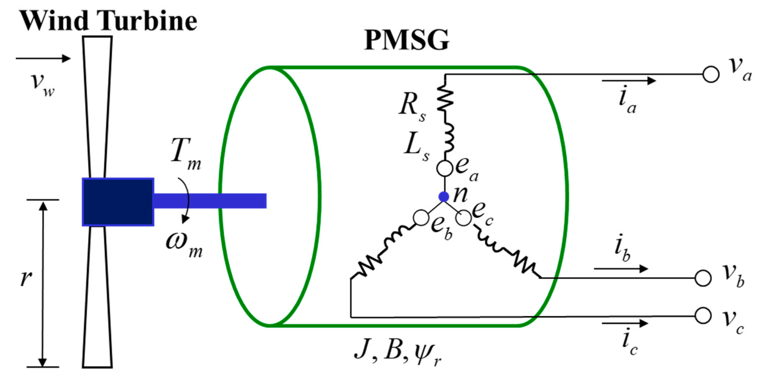
2. Modeling of the PMSG Wind Turbine Generator
As shown in
Figure 1, the simplified structure of a PMSG wind generator can be divided into the PMSG and the wind turbine parts. There are two types of PMSG modeling. One is in the three-phase
a-b-c stationary frame for simulation analysis, and the other one is in the synchronously rotating
d-q frame for the PVOC current controller design which will be described in the next section. The modeling of the PMSG in the three-phase
a-b-c stationary frame, which is a combination of circuit- and equation-based models, is described as follows. The three-phase stator voltage with respect to the generator neutral point
n in
Figure 1 is given as
where
is the stator resistance and the three-phase stator flux linkage is
where
is the rotor flux linkage which is considered as a constant,
is the rotor electrical angle, the mutual inductances are given as
and the self-inductance in each phase is
where
is the stator leakage inductance. All symbols are listed in the Nomenclature at the end of this paper. Under the three-phase balanced condition (
), substituting (2)–(4) into (1), yields
where
is called the stator inductance written as
and
can be seen as the electromotive force (emf) in each phase and written as
where
is the rotor electrical speed. The relationship between the rotor electrical angle and the rotor electrical speed is expressed as
where
is the initial angle position of the rotor. By means of power conservation principle, the generator torque can be written as
where
is the generator’s mechanical speed, which is relative to the rotor electrical speed by
where
P is the magnet pole number of the rotor. Substituting (7) and (10) into (9) yields
From the Newton’s 2nd motion law, the generator rotation speed equation relative to the torque can be expressed by
where
is the wind turbine mechanical torque generated by the wind,
is the moment inertia, and
is the viscous coefficient of the generator.
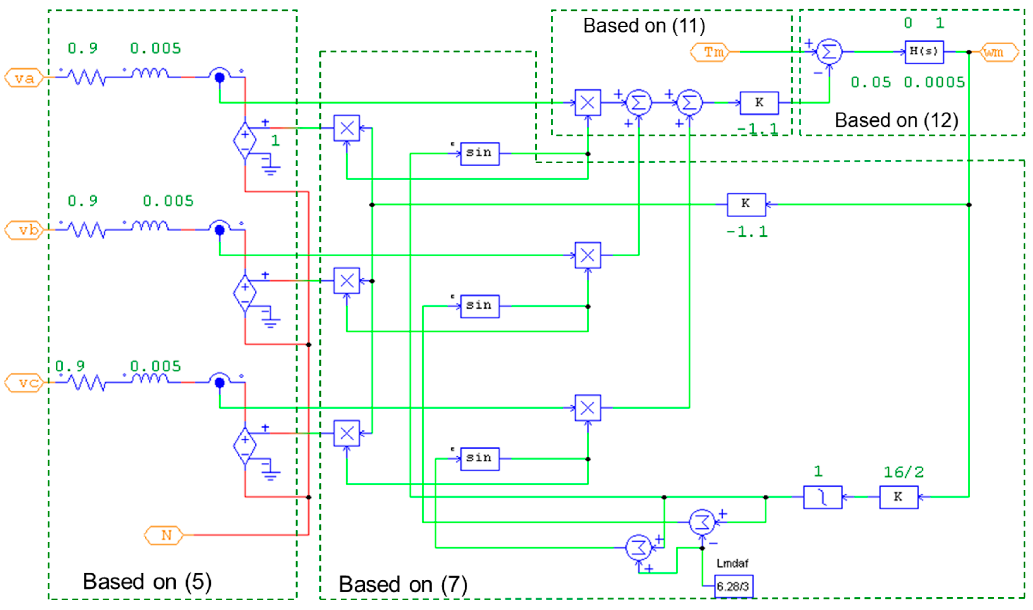
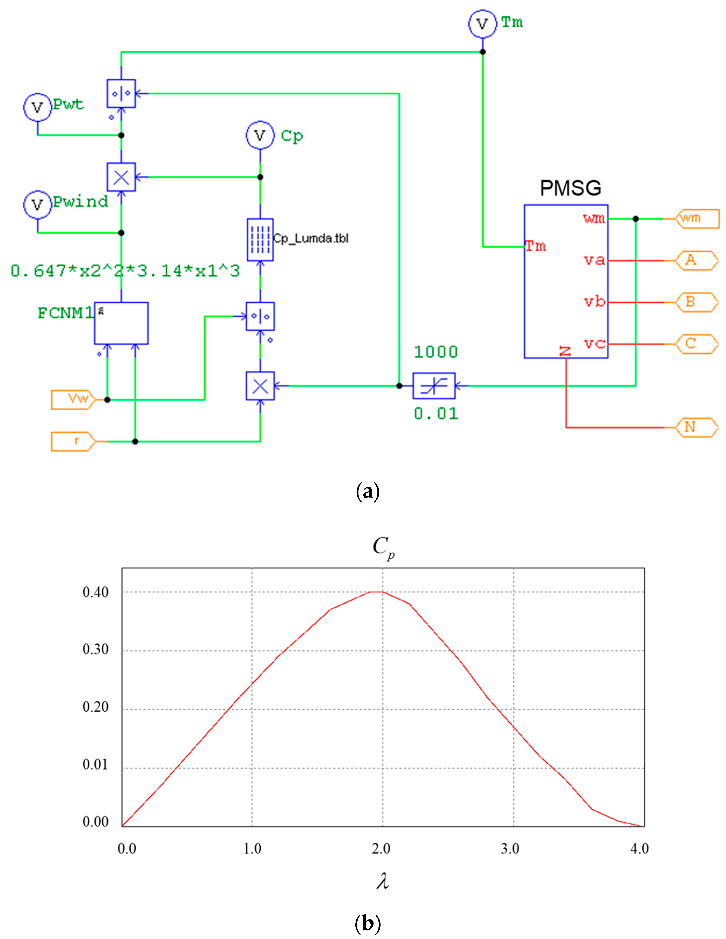
Figure 2 shows the model construction of the PMSG generator in PSIM using the parameters shown in
Table 1. The model consists of an electrical part to produce the three-phase currents based on (5), an electro-mechanical part to produce the generator torque based on (11), a mechanic-to-electrical part to produce the electromotive force based on (7), and a mechanical part to produce the generator speed based on (12).
The input to the PMSG model is the wind turbine mechanical torque,
, which is relative to the wind turbine’s power,
, by
and the wind turbine’s power is written as
where
is the air density,
r is either the blade length of a horizontal-axis wind turbine or the rotation radius of a vertical-axis wind turbine,
is the wind speed, and
is the wind turbine power efficiency for a fixed-blade turbine and is a function of the tip speed ratio which is defined as
The PMSG wind turbine PSIM model by connecting the constructed PMSG model and the wind turbine modeling in (13)–(15) is shown in
Figure 3a, in which a
look-up table is like a hill curve shown in
Figure 3b. The PMSG wind turbine PSIM model block will be used for the simulation analysis in the following sections.
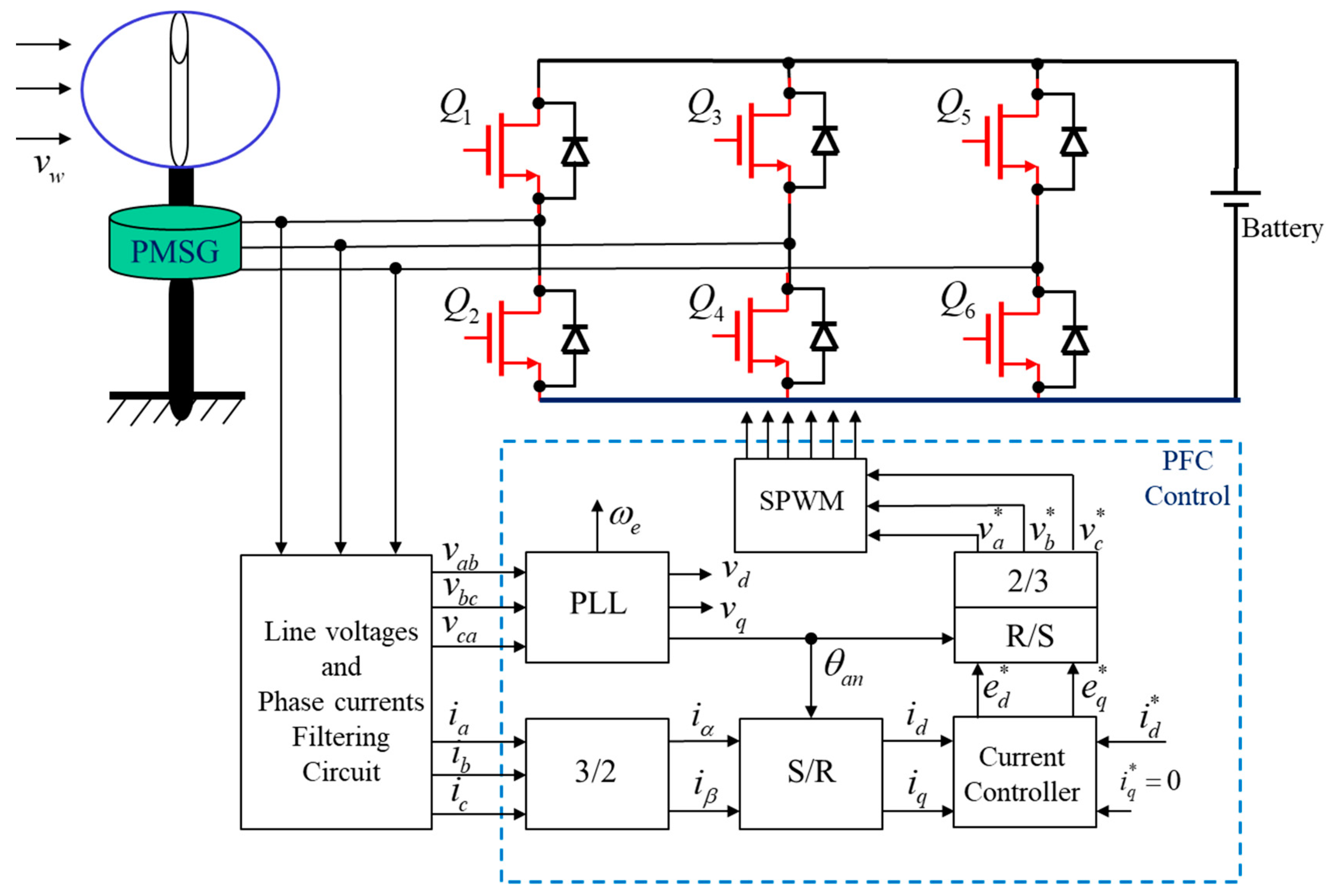
3. The PVOC Current Control Design
Figure 4 shows the system block diagram of the proposed phase voltage-oriented control (PVOC) of a PMSG wind generator with unity power factor correction. The system is operated in two separately rotating
d-q frames. One is for a phase-locked loop (PLL) and the other is for the PVOC current control loop. As the neutral point of the Y-connected generator is hidden and unavailable, the phase voltage of the wind generator cannot be obtained directly. Therefore, the PLL block is firstly used to extract the line voltage angle, and then the phase voltage angle can be obtained by a phase shift of 30 degrees. In the PLL loop, a PI controller functioned as a low pass filter is designed for extracting the phase-voltage angle for the coordinate transformation between the stationary
α-β frame and the synchronously rotating
d-q frame in the PVOC current control loop. The
d-q modeling of the PMSG with the three-phase voltage vector aligned on the
d-axis is then derived and based on which an another PI controller followed by decoupling control is designed, so that the three-phase currents are in phase with the three-phase output voltages of the wind generator. The PLL scheme and the PVOC current control of the wind generator are described as follows.
3.1. The PLL Scheme
The inputs to the PLL loop, which is operated in a rotating
d-q frame, are the three-phase line-to-line voltages. Let the wind generator line voltage vector be
in which the three-phase line-to-line voltage components are written as
where
is the line voltage amplitude,
is the angular frequency,
is the phase angle, and
is the
line voltage argument.
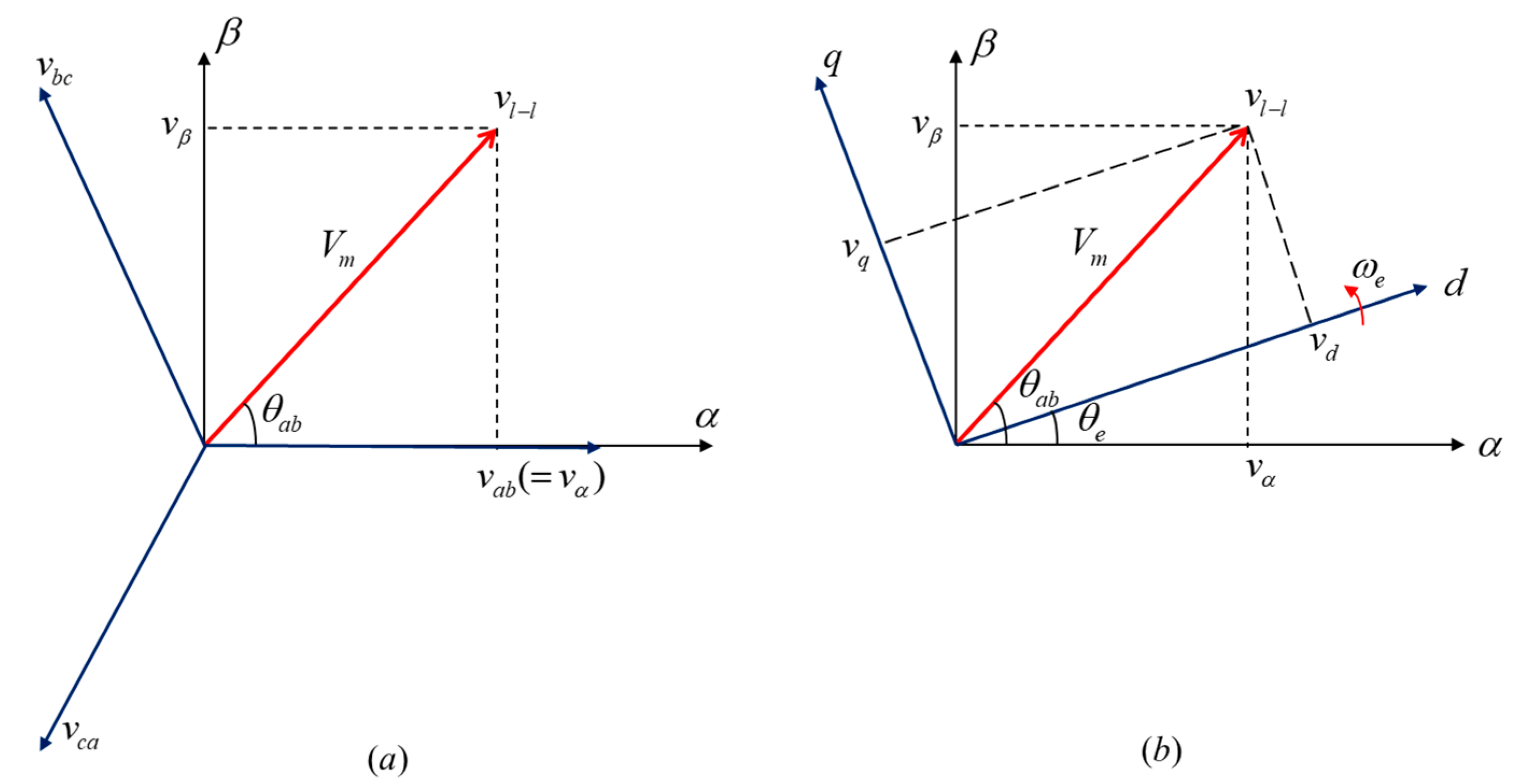
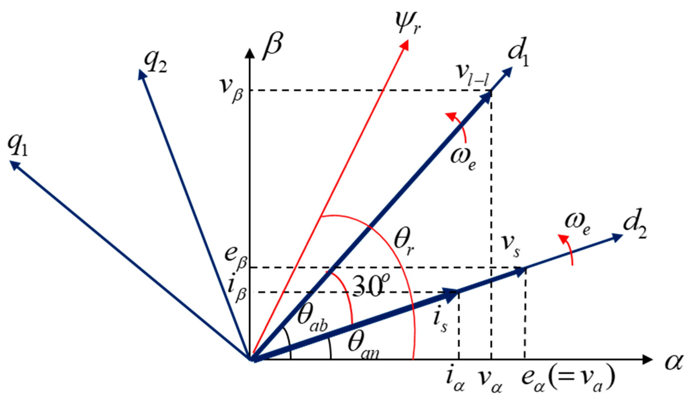
Figure 5 shows the geometric diagram of the line voltage vector in the stationary
α-
β frame and synchronously rotating
d-q frame with the Clarke and Park transformation given by (17) and (18), respectively.
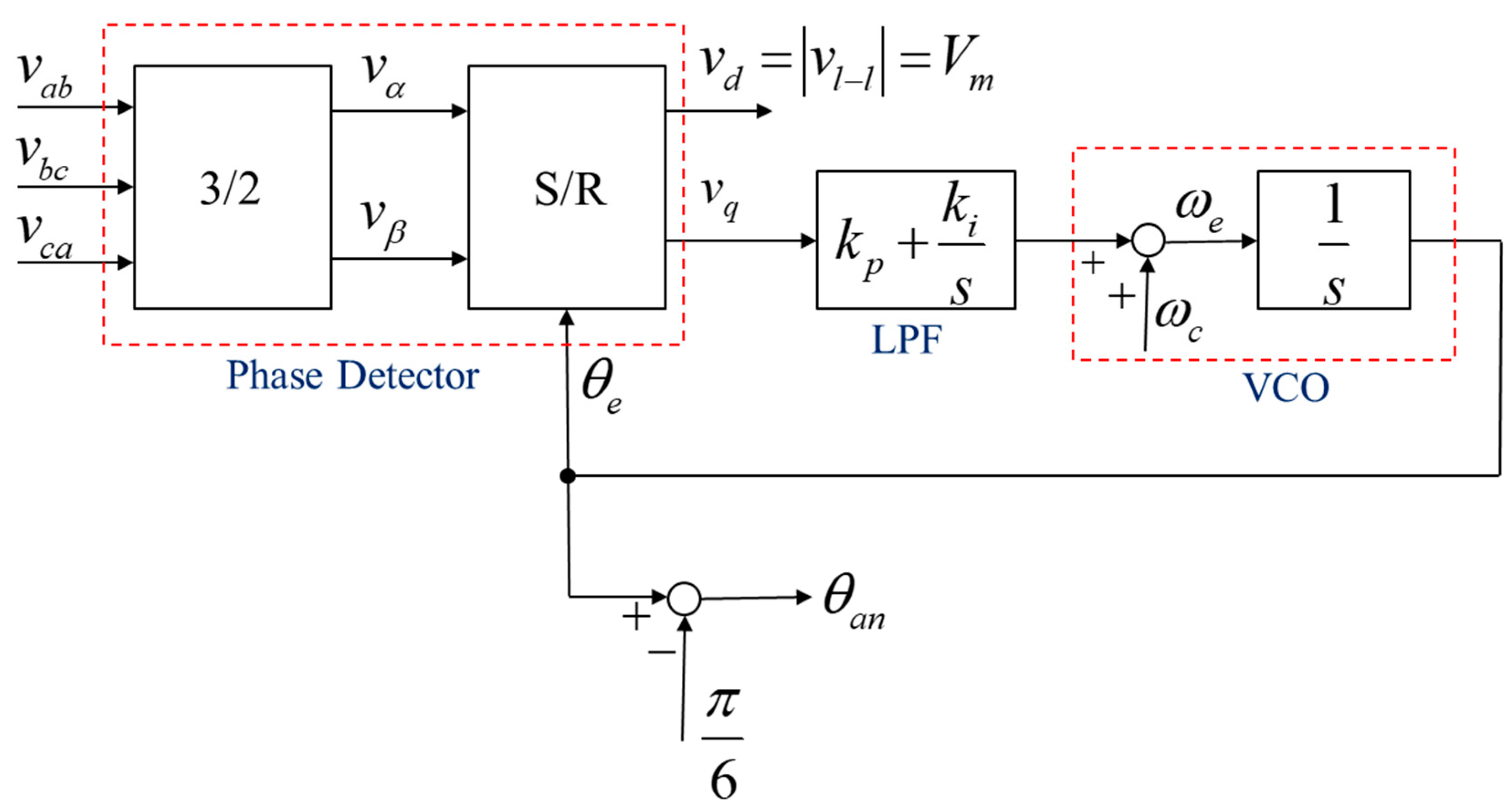
The block diagram of the employed PLL scheme is shown in
Figure 6, which is composed of a phase detector (PD), a low-pass filter (LPF), and a voltage-controlled oscillator (VCO) where
is the center frequency of the VCO as a feed-forward parameter dependent on the range of frequency to be detected [
22]. Substituting (16) into (17) yields
and then substituting (19) into (18) yields
As
, the phase is locked. Then, the second row of (20) can be rewritten as
Thus, the S/R block in the phase detector of
Figure 6 is functioned as a phase subtracter or a phase comparator. As
,
is equal to zero. This means the line voltage vector
is aligned to the
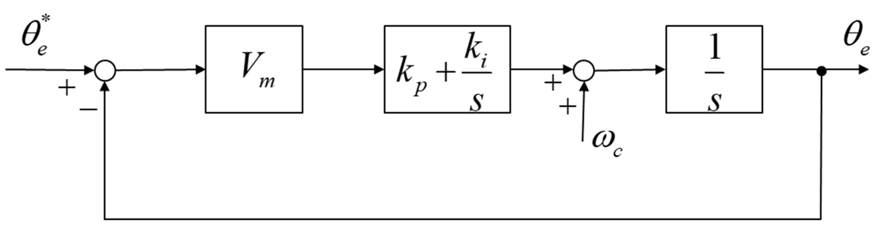
d-axis. To design the PI controller of the phase-locked loop, the transfer-function block diagram can be plotted as shown in
Figure 7. The transfer function from the input
the output
is
where
is called the damping ratio and
is called the undamped natural frequency of the system. From (22), we have
and
Thus, by giving the parameters value of , , and , which can be the generator line-to-line rating voltage, the parameters of PI controller in the phase-locked loop can be obtained by (23) and (24).
After the line voltage phase angle is locked, the phase angle of the phase voltage
is obtained as
The three-phase phase voltage of the wind generator then can be reconstructed by
where the voltage magnitude
can be obtained from the
component of the proposed phase-locked loop in
Figure 6. However, the output line-to-line voltages of the wind generator are PWM switching signals which have to be filtered by a low-pass filter (LPF) to get the three-phase line-to-line fundamental signals before going to the PLL block. The LPF will produce magnitude reduction and phase lag of the input signal, which should be compensated. For a first-order LPF with the following transfer function,
where
is the bandwidth of the LPF. The magnitude reduction and phase lag of the transfer function is, respectively, as
and
Therefore, the three-phase phase voltage of the wind generator in (26) should be modified as
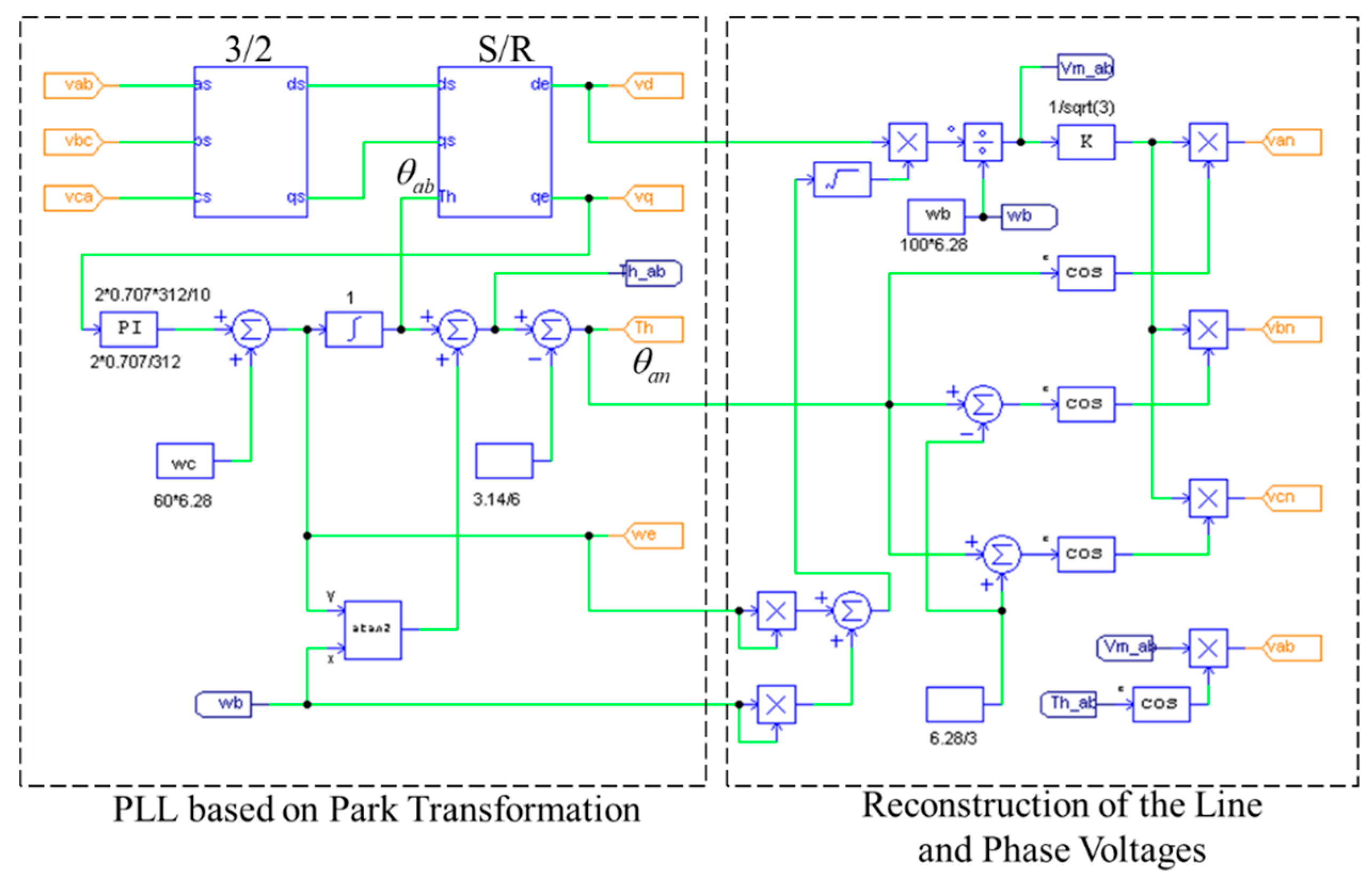
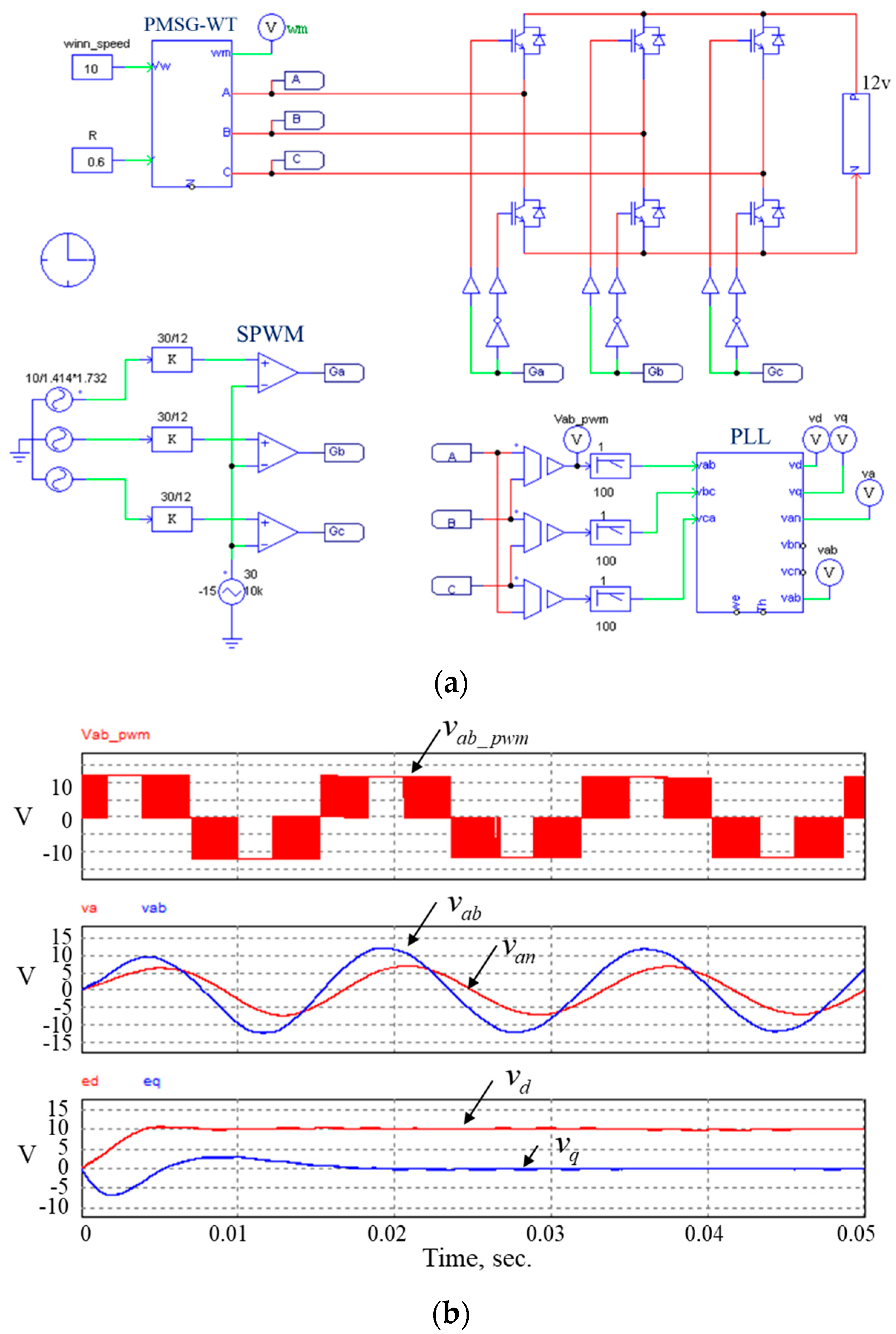
Figure 8 shows the proposed PLL scheme and the reconstruction of the three phase voltages with the magnitude reduction and phase lag compensation due to the LPF effect in PSIM. The simulation verification is shown in
Figure 9. As can be seen, given a 60 Hz, 110 V rms three-phase line voltage, the reconstructed phase voltage
has 30 degrees of phase lag and
magnitude ratio as compared to the line voltage
. Furthermore,
is approaching zero and
is approaching a constant voltage equal to
.
3.2. Current Control with Power Factor Correction
The current vector control method proposed in this paper for unity power factor correction to control the three-phase phase currents in phase with the three-phase phase voltages is voltage phase-oriented with the three-phase voltage vector aligned on the
d-axis. To do this, the phase angle of phase voltage extracted from the PLL scheme described above is used for the coordinate transformation between the stationary
α-β frame and the synchronous
d-q frame. A PI current controller is designed in the
d-q axis, respectively. The current references for the
d-q components are as follows:
where
can be given by the outer-loop power signal feedback (PSF) MPPT control [
7,
8]. Under this control method, the three-phase currents can be controlled as
in which the argument
has been compensated by adding the term in (29) due to the LPF. The modelling and design of the PI current controller is described as follows.
With the three-phase voltage vector aligned on the
d-axis, the three-phase stator voltage equation in the
d-q frame can be derived by substituting the three-phase stator voltage Equation (4) in
Section 2 into (33) and (34) as follows.
where
and
are the stator voltage components in the second
d-q frame (
), which has a phase lag compared to the PLL
d-q frame (
), as shown in
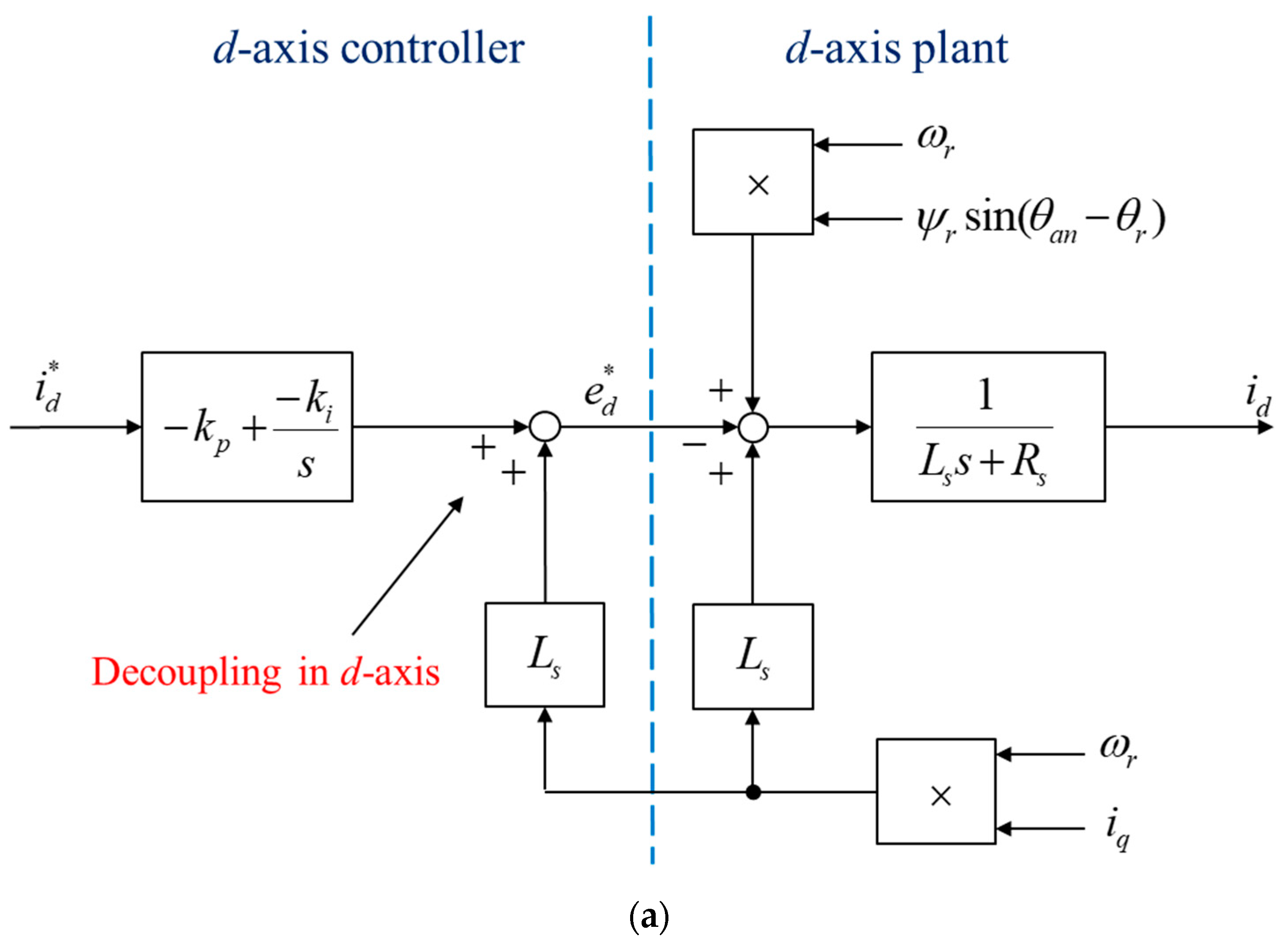
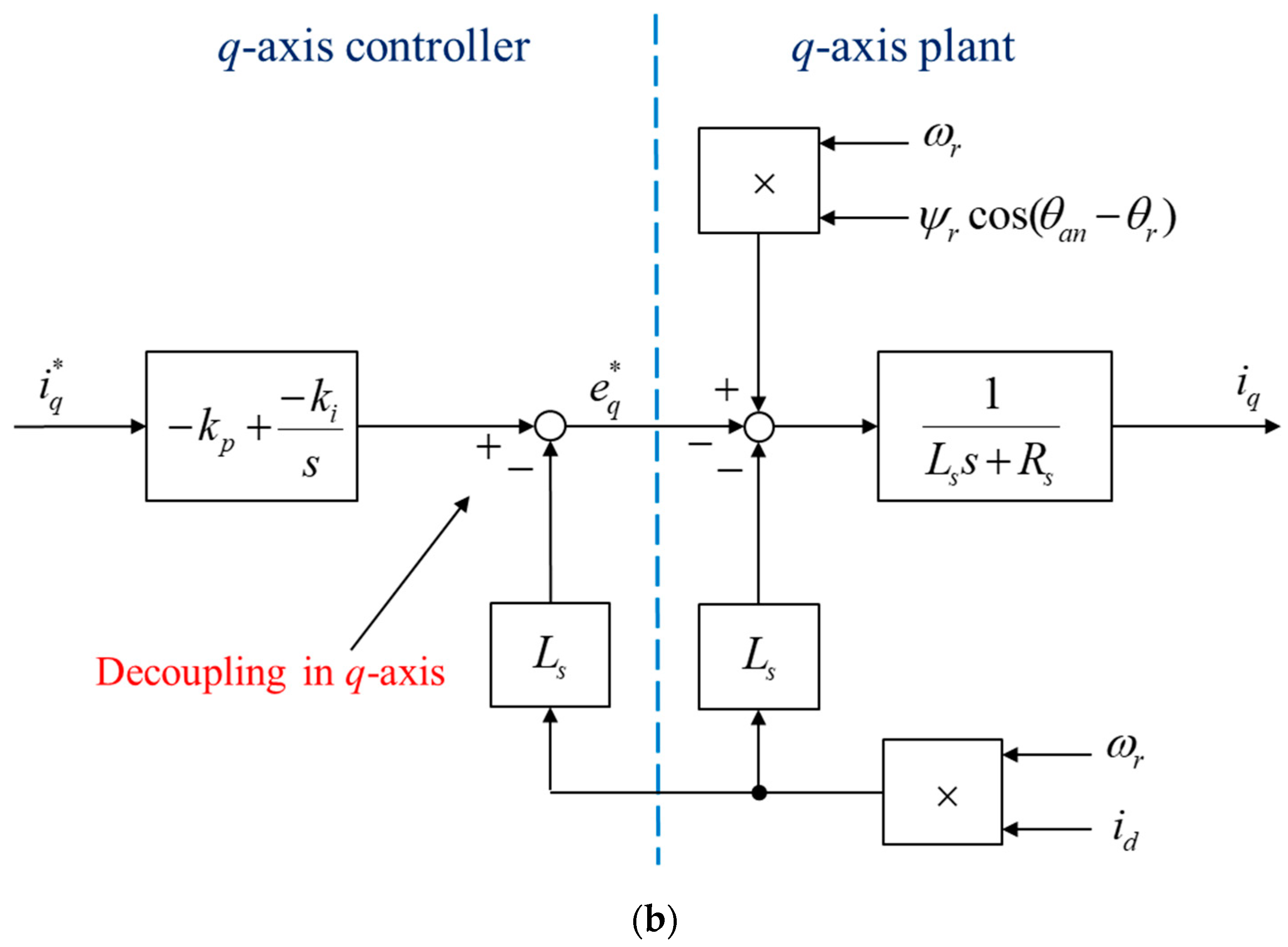
Figure 10. Then, the state equation can be obtained from (35) as
Figure 11 shows the controlled plant and the controller block diagram in the
d-axis and
q-axis, respectively. As can be seen, the PI controller is followed by a decoupling compensation for eliminating the coupling effect of
to
on the
d-axis plant and
to
on the
q-axis plant, respectively. The term
on the d-axis plant and
on the q-axis plant can be seen as a disturbance for the controlled current components
and
, respectively, which can be regulated by the PI controllers.
By using the pole-zero cancellation method with the decoupling control in the
d-axis and
q-axis, respectively, the closed-loop transfer function for the both axes are the same and can be written as a first-ordered system by
where
K is the bandwidth of the system with
Thus, by setting the bandwidth of the closed-loop current control system to be 300 Hz, the PI controller parameters can be obtained.
4. Simulation and Experimental Verifications
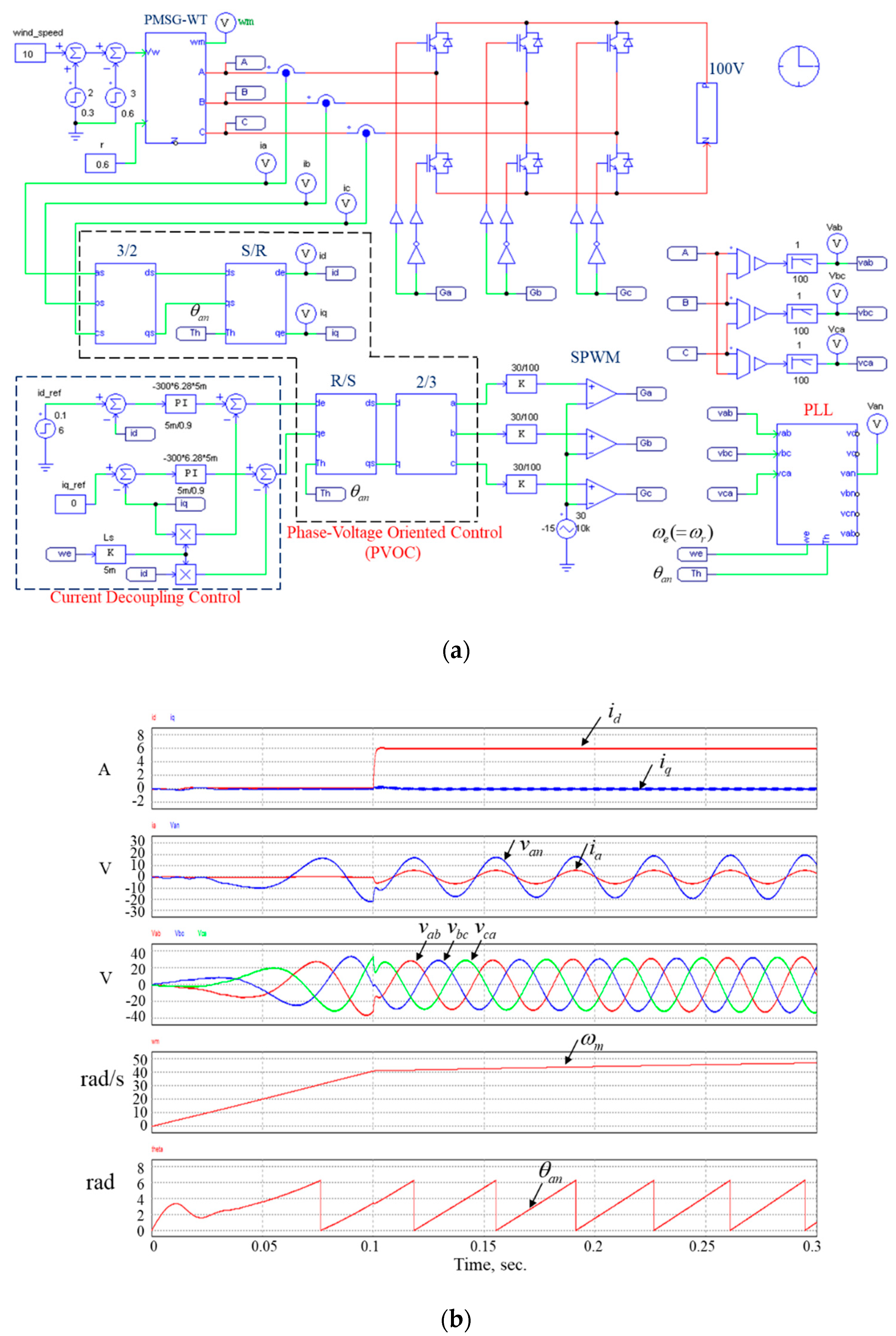
The simulation verification of the phase-voltage oriented vector control of a wind generator for the unity power factor correction in PSIM is shown in
Figure 12a. Given the wind speed of 10 m/s and the current reference
after the time of 0.1 s, the simulation result is shown in
Figure 12b. As can be seen,
is approaching zero because the zero current reference is given on the
q-axis and
is rising quickly to a constant value equal to
. Furthermore, the phase current
is in phase with the phase voltage
. The reconstruction of three phase line voltages
, the generator rotation speed
, and the theta angle
from the PLL block are also shown in the figure. It can be seen that the generator rotating speed is increased linearly due to no load before the time of 0.1 s. The generator rotating speed is increased with slower slope because the generator load torque is produced when the current reference of 6A is given.
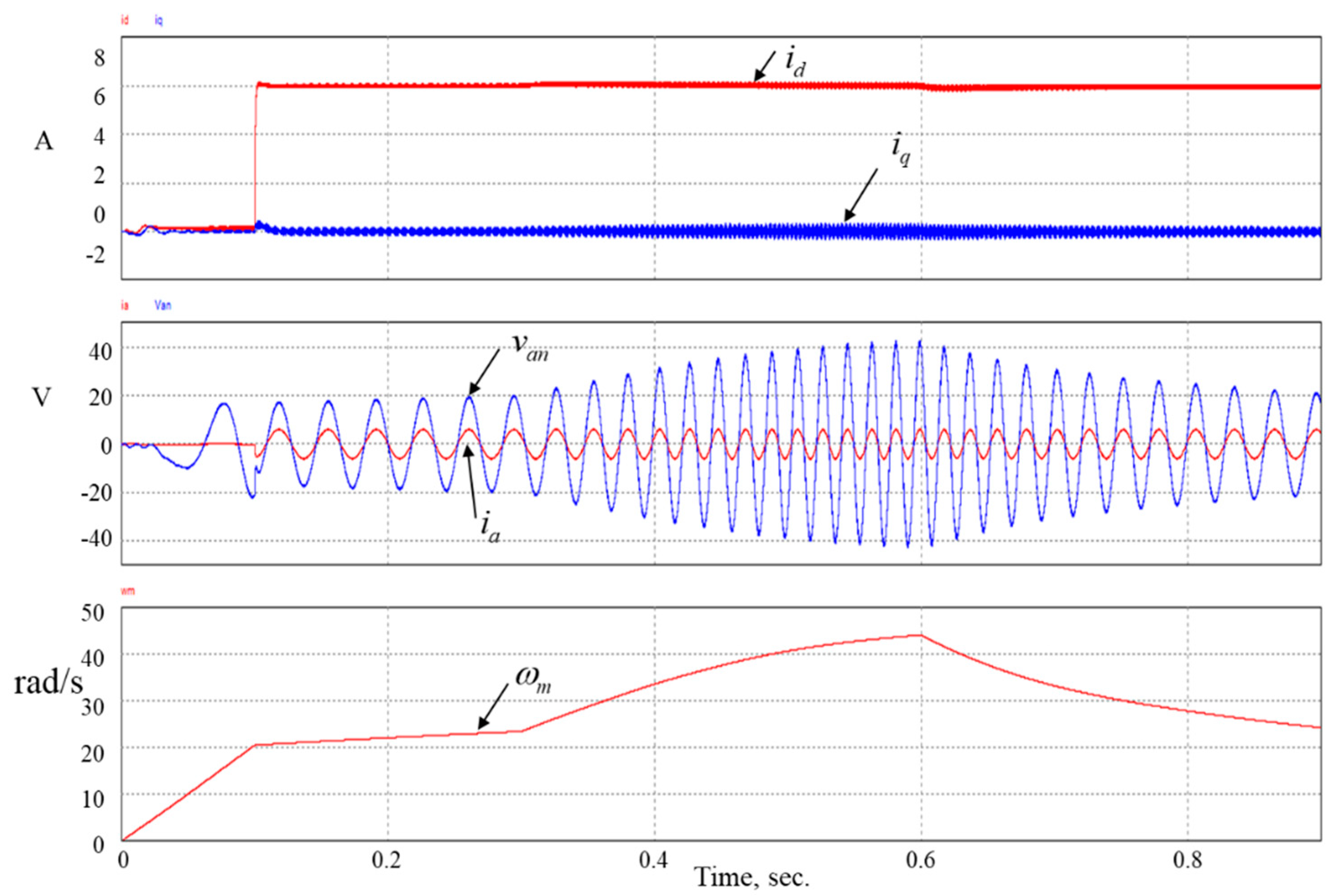
Figure 13 shows the simulation waveforms for the wind speed variations with sudden change from 10 m/s to 12 m/s at 0.3 s. and down to 9 m/s at 0.6 s. As can be seen,
remains at the constant value of 6A and
remains at zero. The phase current
is in phase with the phase voltage
even though the phase voltage increases from 0.3 s to 0.6 s, and then decreases from 0.6 s to 0.9 s due to the wind speed variations. The generator rotating speed is also increasing and then decreasing corresponding to the wind speed sudden variations. The simulation waveforms in
Figure 12 and
Figure 13 indicate the correct operation of the proposed PLL and PFC control scheme.
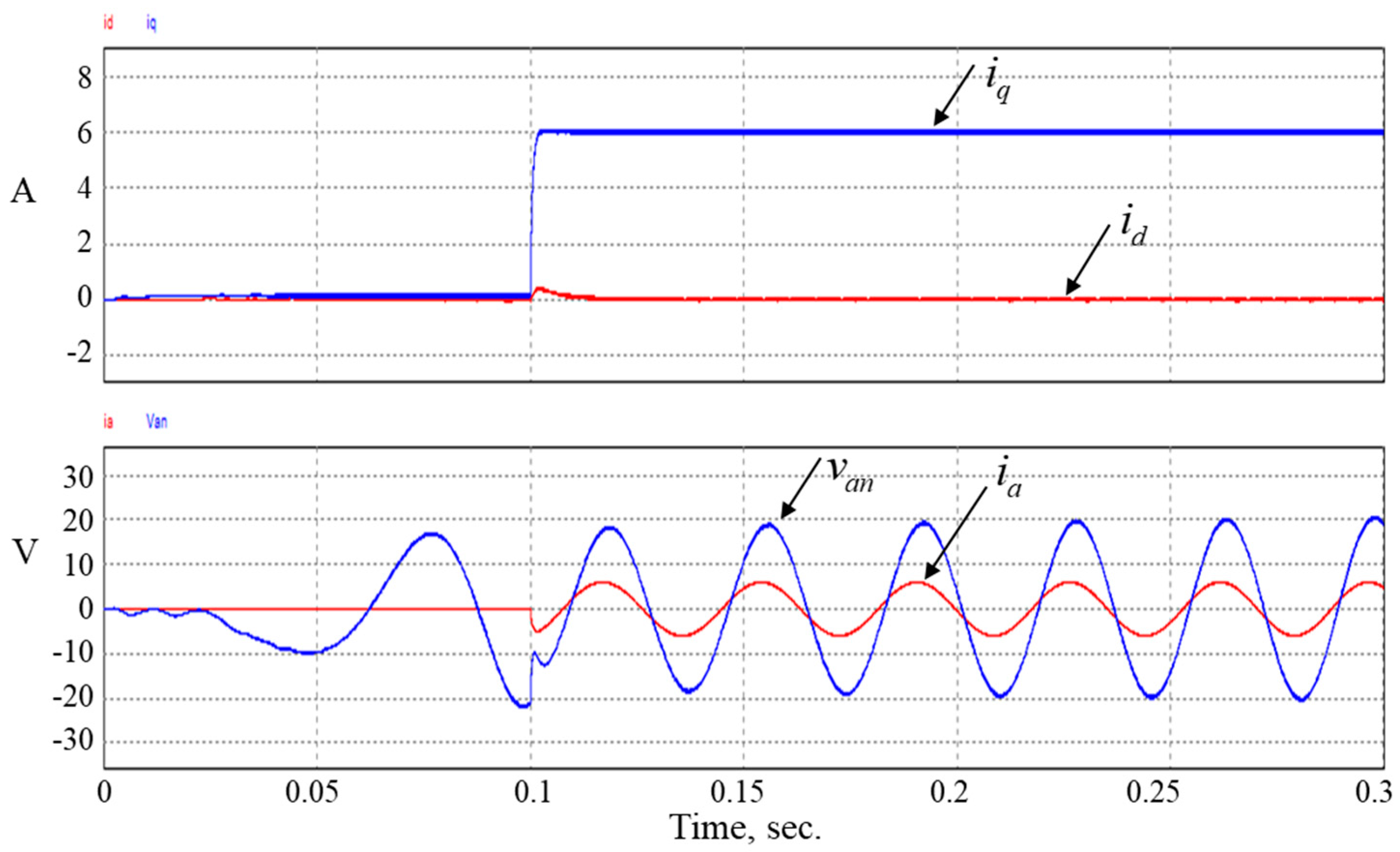
The developed method is compared with an existing PFC control of a directly driven PM wind generator which is based on RFOC control by calculating the stator current using the generator parameters [
20]. In the conventional RFOC current control method, the phase angle for the Park and inverse-Park coordinate transformation is the rotor flux angle with the magnet rotor flux vector oriented as
d-axis. The stator voltage equation in the
d-q frame can be derived by setting
in (35) as follows.
If not using PFC control, the current reference is given on the
q-axis with
, and the simulation result is shown in
Figure 14. As can be seen,
is approaching zero and
is rising quickly to a constant value equal to
(6 A). However, the phase current and the phase voltage are out of phase with phase current leading the phase voltage.
For unit power factor control, the existing method with RFOC presented in [
20] is on the basis of the following condition:
In the steady-state operation, the directive terms in (39) can be neglected, so it can be rewritten as
Substituting (41) into (40) yields
The above equation can be solved approximately as
because
, and hence
.
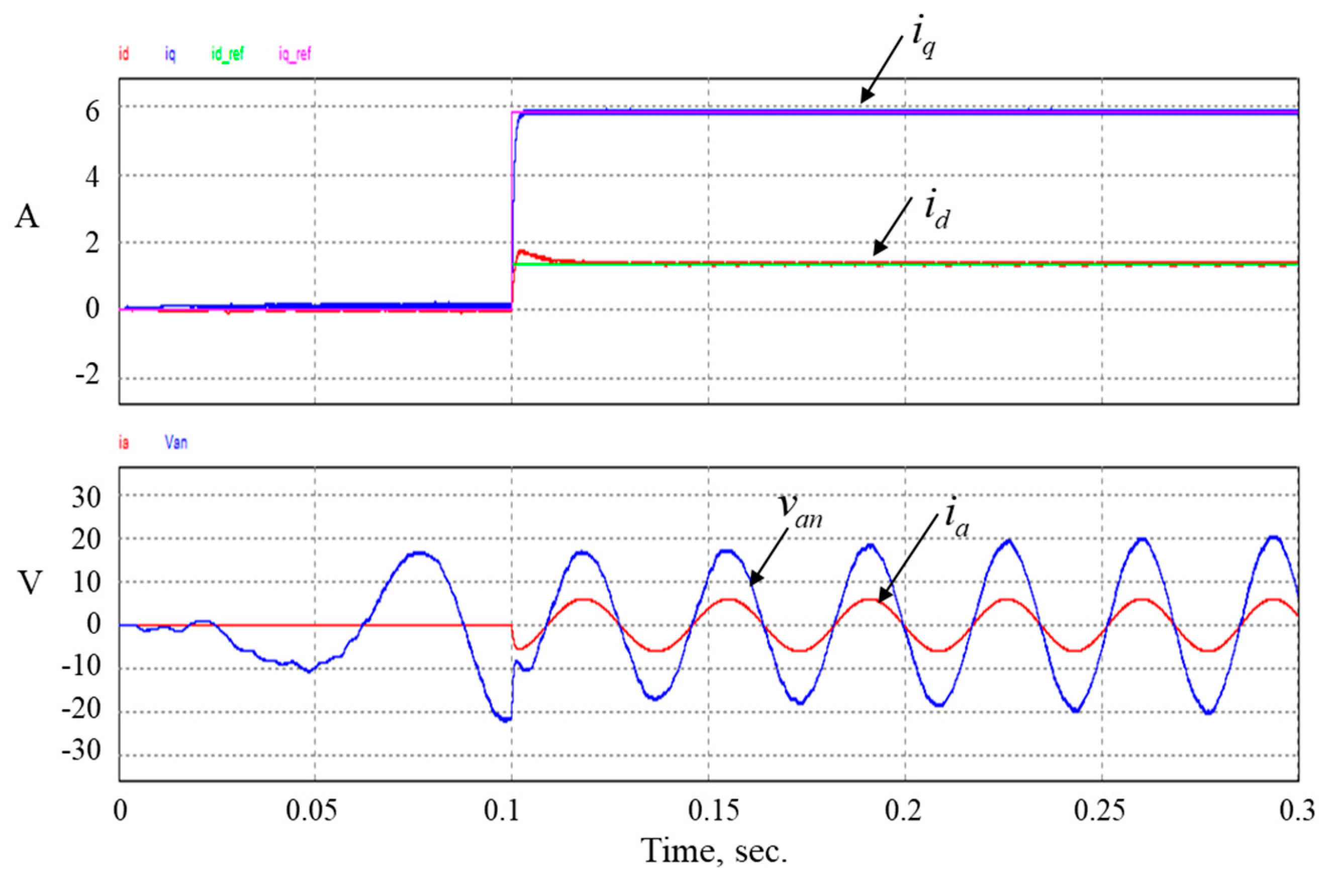
Figure 15 shows the simulation result of the existing PFC control with RFOC method given the current control reference according to (43) and wind speed of 10 m/s. As can be seen, the phase current looks in phase with phase voltage. Actually, with the approximation in (43),
Thus, there is little phase difference between the phase current and the phase voltage due to the approximation. The comparison of the above three current control methods is summarized in
Table 2. As can be seen, the proposed PFC current control method based on PVOC has better power factor than other two control methods based on RFOC and has no requirement of the rotor position sensor or sensorless estimator.
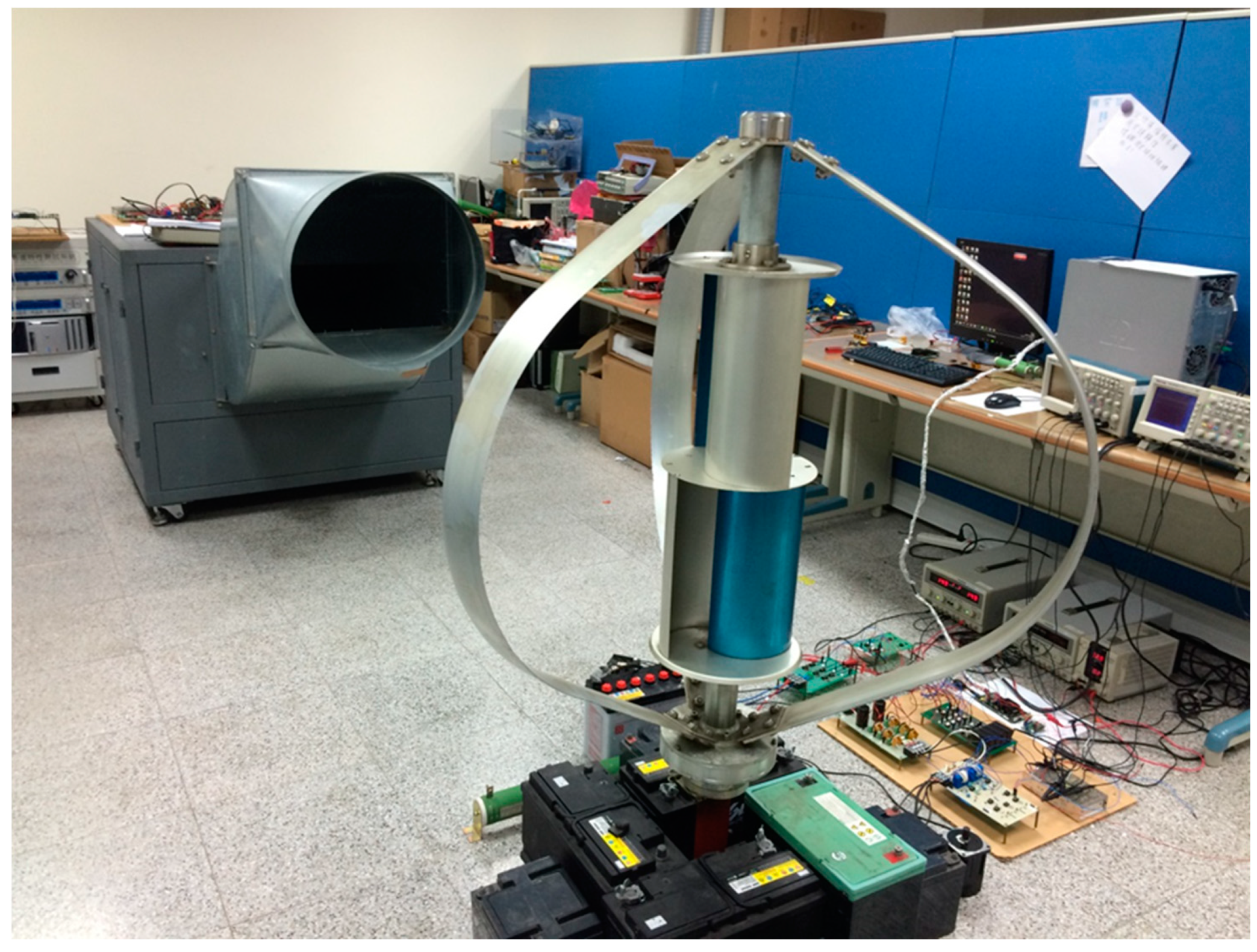
Figure 16 shows the experimental platform for the verification of the proposed PVOC control of a wind generator for unity power factor correction. The wind is generated by an inverter driven blower which can produce variable wind speed. A vertical axis wind turbine charger, which consists of a 400-W wind turbine, a PWM controlled rectifier, a 12-V battery, and a TI TMS320F28335 DSP chip, has been employed to verify the proposed control method.
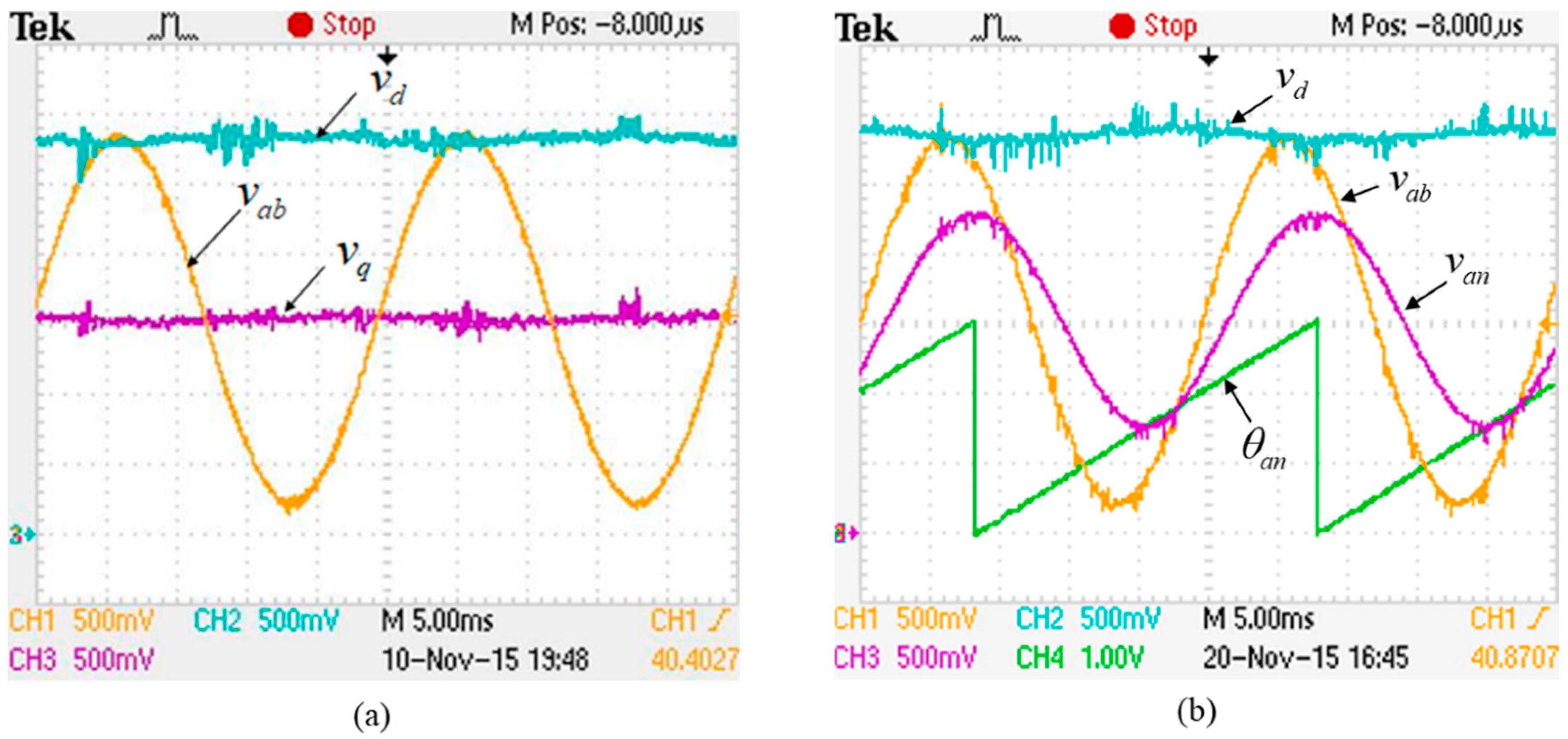
Figure 17 shows experimental waveforms for the PLL scheme. As can be seen from
Figure 17a that after the phase is locked, the
q-component of the line voltage,
, is equal to zero and the
d-component,
, is kept to be near a constant which is the amplitude
of the line voltage. The waveforms of the phase voltage argument,
, together with the reconstruction of the phase voltage
and the line voltage
from the PLL block are shown in
Figure 17b. As can be seen, the phase voltage
has a phase lag of 30 degrees and about
of amplitude compared to the line voltage
.
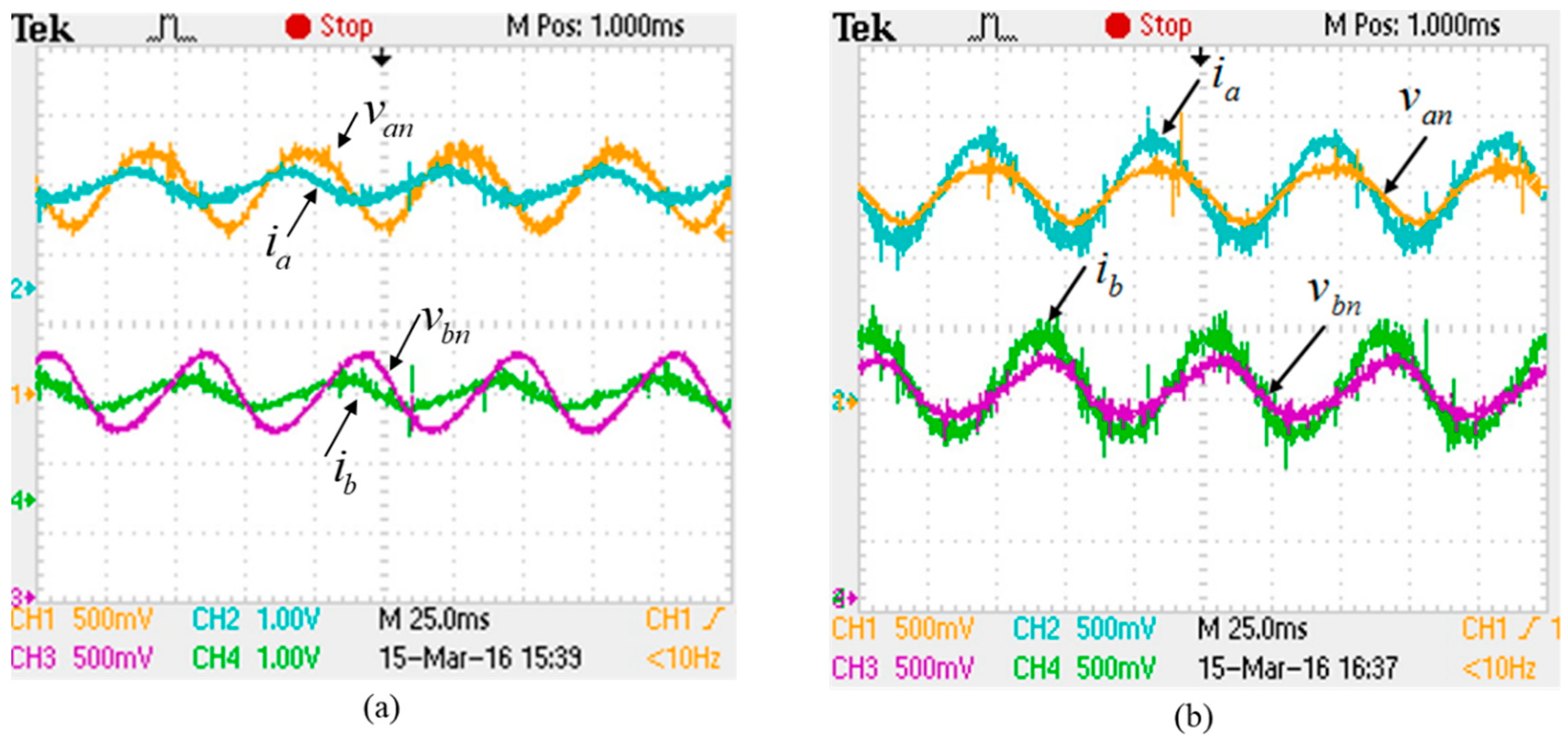
Figure 18 shows the comparison of experimental results with and without using PVOC control. As can be seen from
Figure 18a that the phase currents lead the phase voltages in the open-loop PWM control test. But, as can be seen from
Figure 18b, the phase currents are almost in phase with the phase voltages with the proposed closed-loop PVOC control method.


