Abstract
Ground coupled heat pumps are a notoriously efficient system for heating and cooling buildings. Sometimes the characteristics of the building and the user’s needs are such that the amount of heat extracted from the ground during the winter season can be considerably different from the amount injected in summer. This situation can cause a progressive cooling or heating of the ground with a negative effect on the energy efficiency and correct operation of the system. In these cases, an accurate sizing has to be done. In systems already built, it could be necessary to intervene a posteriori to remedy an excessive ground thermal drift due to the energy unbalance. In this work, such a situation relating to a real office building in Italy is investigated and several solutions are examined, one of which has been then implemented. In particular, a hybrid heat pump using as heat sink both the ground and external air is compared with common solutions through computer simulations using a dedicated numerical model, which has also been compared with monitoring data. As a result, the hybrid heat pump shows better performance and limits the thermal drift of the ground temperature.
1. Introduction
Climate change is a major challenge for the international Community. European Countries aim to achieve net zero emissions by 2050 [1,2]. An important contribution to achieving this goal can come from buildings that account for up to 36% of final energy use [3]. Nowadays, heating and cooling energy consumption in buildings is mainly based on fossil fuels [4], which considerably contribute to greenhouse emissions. Moreover, fossil fuels are limited, and their price is highly variable. To drive the decarbonization process, renewable energy technologies (mainly based on solar, wind, biomass, and geothermal source) are increasingly used. However, the first step is surely to limit the energy use in buildings by adopting efficient solutions. This can be obtained by optimizing the building envelope with suitable materials and technologies [5]. Once this is done, new systems based on the exploitation of renewable energy sources can be installed to increase the energy efficiency.
Heat pumps are certainly one of the most efficient solutions for heating and cooling in buildings [6]. The heat pump moves heat from a thermal source to the building in heating mode and rejects the thermal load from the building to the heat sink when it works in cooling. The thermal source/sink can be air, water or ground. When external air is used as a thermal source/sink, the energy efficiency of the heat pump is affected by its temperature variation; in addition, the energy performance can decrease due to the defrosting cycles that can occur during the winter. Ground or groundwater flow temperature is more stable during the year and also closer to the indoor air temperature of the building than external air temperature, consequently the energy efficiency of a ground source heat pump (GSHP) is higher than that of an air source heat pump (ASHP) [7]. This aspect is well-known from thermodynamic point of view and several analyses are reported in literature. For example, Esen et al. [8] carried out a comparative analysis between a GSHP and an air source heat pump in heating mode, concluding that GSHP presented higher energy efficiency, therefore also lower operating costs. Similar results were also found by Lu et al. [9] in the Melbourne climate.
The use of GSHP systems for HVAC in buildings has been pushed in the last few years as a promising good solution for reducing CO2 emissions and operating costs [10], in both residential and commercial buildings, even if the main barrier is surely their relatively high capital cost. The closed loop is the most widespread configuration in GSHP systems. In this case, vertical or horizontal ground heat exchangers connect the ground to the evaporator or condenser of the machine. Vertical configurations of ground heat exchangers (Borehole Heat Exchangers, BHEs) are more frequently used to limit the use of land area [11], especially in commercial buildings.
The design of a GSHP system requires a deeper and more adequate knowledge than that of traditional plants using gas boiler or air source heat pump because the performance depends on the thermal behavior of the borehole heat exchangers over the years. The designer must verify that the high efficiency of the system is maintained throughout the operating years. In fact, when the annual load profile on the ground side is unbalanced, thermal drift of the ground temperature occurs, and this affects the heat pump’s energy efficiency. Several methods and commercial tools have been developed to design GSHP systems [11,12,13,14]. Three types of key input data are fundamental for the design: (a) the building thermal load profile, (b) the energy efficiency of the heat pump and (c) ground properties. While the building thermal loads depend on climate, envelope, internal gains, etc., the energy efficiency of the heat pump highly depends on the return fluid temperatures on both the building and ground side. Moreover, the ground heat transfer rate necessary for sizing the borehole heat exchangers depends on the ground thermal properties that can be evaluated via thermal response testing measurements and analyses [15,16,17]. In light of all these issues, integrated computer simulations through suitable tools that, simultaneously, consider the building, heat pump and borehole heat exchangers represent the best solution to analyze the thermal performance of the GSHP system over time. EnergyPlus software [18] is a free tool that allows for this kind of analysis. It uses the well-known approach of the g-functions [19] to simulate the BHEs. The software includes some sets of g-functions which, however, have a limited validity. For greater precision in simulations, especially in the case of a retrofit, the g-function is an input in EnergyPlus that has to be calculated by the user via dedicated tools (e.g., [13,20,21,22]). The g-function is strictly related to the local ground properties, layout and number of borehole heat exchangers that cannot change during the simulation time. As mentioned, the energy unbalance of the ground heat exchangers is the origin for the performance decay of the heat pump [23]. When the building load profile is unbalanced, if the GSHP has to cover the total load, the borehole field has to be sized for that scope and, consequently, the initial cost increases. Sometimes, the designer can adopt measures on the envelope to balance the thermal load profile [24]. However, when the thermal unbalance on the ground side is high and it cannot be avoided, hybrid GSHP systems can be a valid solution, also decreasing the initial investment for borehole drilling [25,26,27]. Among hybrid systems, the dual source heat pump is surely interesting. In this case, the heat pump can use the most favorable source or sink between air or ground [28,29].
A non-optimal design or, as often observed in practice, discordant hypotheses regarding the building thermal load profile or ground properties, and the consequent temperature drift, can lead to long-term performance degradation with a resulting increase in operating costs, and possibly discomfort for users. This circumstance may arise when the users’ needs change, leading to a situation where the assumptions made for the thermal loads calculation in design phase are significantly different from the reality.
One of the main limits of GSHP systems concerns the possibility to modify the borehole field layout and HVAC system once the plant has been completed. When the GSHP system presents a problem, the designer has to stem the cause and choose the best solution, in terms of both efficiency and investment costs. A smart solution in GSHP systems when, for example, the heating or cooling output provided is not sufficient to maintain the required indoor environmental conditions, is the installation of an auxiliary system (e.g., an additional air-to-water heat pump, gas boiler, chiller) coupled in parallel to the existing GSHP. Another possibility is the installation of an additional condenser or evaporator. The adoption of a dual source heat pump has been dealt with in several works, both for new buildings and with reference to retrofitting actions in which the entire system of an existing building was renovated [30,31,32]. Less frequent is the case where the system has to be modified with the least invasive intervention possible.
Regardless of whether the external source is foreseen in the design phase or is the result of a retrofit operation, the problem appears of establishing a switching strategy between the use of the borehole field and the external source (air or water). In fact, in addition to the benefit of eliminating or reducing the thermal unbalance on the ground and the consequent drift of its temperature, an appropriate selection of operation can lead to an appreciable benefit in terms of energy use, since for long periods the ground may be less advantageous than the external source, in relation to the trend of climatic conditions. In the case that the external thermal source is air, the switching parameter is air temperature while if the external cooling apparatus is a cooling tower the switching strategy can be advantageously based on wet bulb temperature [33].
An action on a GSHP system is usually more complicated and expensive in terms of costs, compared with other systems. The main reason is that a change in the borehole field requires the installation of additional BHEs for which further land area should be available around the building and invasive intervention is required. Moreover, even if space is available for new BHEs, the zone could be no more accessible by the drilling equipment once the building has been constructed.
Starting from these considerations, the retrofit of the GSHP systems can be realized in different ways. The issues relating to sizing of the plant, modification of the thermal load or damage of some BHEs, are usually highlighted by inadequate temperature levels of the heat-carrier fluid circulating in the ground loop. At the same time, a diagnostic approach requires knowing other information related to the operating conditions (i.e., electric power used by the compressor, etc.) that lead to establishing energy balance and energy performance calculations at the heat pump level. For instance, if the temperature difference at the heat pump agrees with the value assumed in the design phase, the cause of the system’s underperformance has to be found on the side of the BHEs. Possible causes of such an issue include a thermal drift of the ground temperature, an inadequate sizing of the borehole field, or unbalanced piping network.
Drawing inspiration from the mentioned issues, this work focuses on the retrofit solutions of an existing GSHP system installed in a cooling dominant office building located in Padova (Italy). The system consisted of a common ground coupled heat pump with 16 double U-tube borehole heat exchangers and it was operational since 2004. The operating conditions of the system changed over the years and a considerable thermal unbalance on the ground side has occurred. Moreover, the heat pump was one of the first installations of GSHP in Italy, thus it was an experimental specimen close to obsolescence. Therefore, a retrofit was necessary to improve the energy efficiency and limit the thermal drift of the ground temperature. In this analysis, three different retrofit solutions are analyzed: (i) the only change in the heat pump, (ii) the installation of a hybrid heat pump using both air and ground as a heat sink, (iii) the installation of the other two borehole heat exchangers. As the current tools are not able to simulate all the solutions, the analysis is carried out through a numerical model that was appropriately modified to allow for the consideration of each proposed configuration. The three options are compared, considering both the long-term energy efficiency and investment–operation costs.
2. Method
Starting from lack of EnergyPlus, the Capacity and Resistance Model (CaRM) [34] was used in this work to simulate the borehole field. CaRM can be easily modified and adapted to a given variation of the investigated case study. The model uses the analogy with an electrical network to solve the transient heat conduction problem into the ground, grouting material and piping network. As shown in Figure 1, the model considers the heat conduction along both depth and radial direction as well as the heat balance on the ground surface in terms of convection and short- and long-wave radiation contributions. The domain is divided in three main zones: (i) the surface, (ii) the borehole and (iii) the deep zone. In each zone, an appropriate heat transfer model is implemented—in the surface and deep zones, the heat transfer is modeled only along the depth direction, whereas in the borehole zone (i.e., the zone surrounding the borehole heat exchanger) the heat transfer is modeled along both the radial and depth directions. A significant feature of CaRM is the consideration of the thermal capacitance of the both heat-carrier fluid and grouting material, therefore sub-hourly computer simulations can be carried out. The domain is divided in several thermal nodes for which the heat balance equations are written, obtaining a linear system of n equations in n unknown terms (i.e., the temperature of each thermal node).
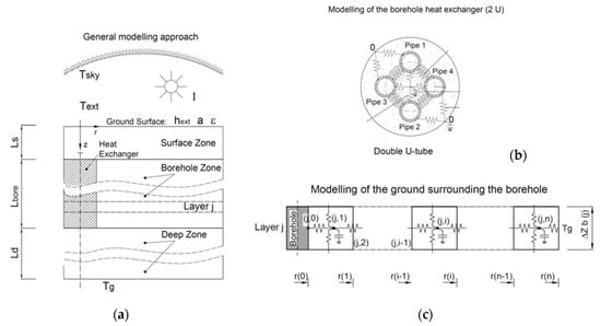
Figure 1.
Scheme of the CaRM approach: (a) general concept, (b) modeling of the BHE, (c) modeling of the ground layer.
In CaRM, when the inlet fluid temperature to the borehole field is used as input, the outlet fluid temperature is calculated considering the heat transfer rate with the ground and all other boundary conditions. This approach allows for linking CaRM to a heat pump model—the outlet fluid temperature from the borehole field is the entering fluid temperature to the heat pump. Considering the building thermal load and the return fluid temperature from the building plant, the heat pump model can calculate the inlet fluid temperature to the borehole field. To integrate such non-linear relationship, an iteration loop is executed until the difference on the ground heat load between two consecutive iterations is less than a predefined tolerance (which is set equal to 100 W). At the end, the energy performance of the entire system (heat pump and borehole heat exchangers) can be evaluated. In this case, the building load profile is considered as an input of the model and, consequently, the return fluid temperature from the building was calculated using the total mass flow rate and the supply fluid temperature set on the building side.
The heat pump was modeled using the same approach of EnergyPlus [18]. To this purpose, both water-to-water heat pump and air-to-water chiller were modeled to consider a hybrid system as a possible retrofit solution.
The energy performance of the water-to-water heat pump is evaluated considering the following relationships to calculate the thermal capacity and electrical power in heating and cooling mode as a function of the entering fluid temperatures and volumetric flow rates at the heat pump on the ground and building side. In heating mode, the thermal capacity and electrical power of the heat pump are calculated using Equations (1) and (2):
In cooling mode, these variables are calculated via Equations (3) and (4):
In the previous equations, Q, Pel, T and refer to the thermal capacity of the heat pump, the heat pump’s electrical power, the entering fluid temperature to the heat pump and the volumetric flow rate, respectively. The subscripts L, S, nom and ref stand for load side, source side, nominal and reference, respectively. Finally, A, B, C and D are the coefficients of the water-to-water heat pump model used in this work and presented in Section 3.
The cooling operation of the machine equipped with air-condenser was modelled by means of a similar approach [18]. In particular, the available cooling capacity is calculated as a function of the leaving chilled water temperature (Tcw,l) and entering condenser fluid temperature (Tcond,e) by:
where a, b, c, d, e and f are the coefficients of the air-condenser model used and presented in Section 3. The variation in the energy input to cooling output ratio (EIR—i.e., the inverse of the EER value) is calculated via the following equation as a function of the leaving chilled water temperature (Tcw,l) and entering the condenser fluid temperature (Tcond,e):
In this case, the part-load behavior is considered through the parameter PLR—i.e., the part-load ratio defined as the actual cooling load divided by the available cooling capacity. The quadratic curve of EIR as a function of PLR (Equation (7)) is used to cover the cooling load profile:
When the part-load ratio is lower than the minimum part-load ratio, the machine starts on-off cycles to match low cooling loads of the building. To evaluate the electrical energy consumption, when the parameter PLR is less than the minimum value (PLRmin), the following coefficient is used:
Finally, the electrical power of the compressor is calculated by Equation (9):
All the coefficients of the previous equations (A, B, C, D, a, b, c, d, e, f) are calculated according to Tang [35], using data from the manufacturer to fit the behavior of the heat pump under different operating conditions. When the thermal/cooling capacity and the electrical power in water-to-water and air-to-water operation have been assessed, it is possible to calculate the energy efficiency at each time step.
Equations (1)–(9) have been implemented in CaRM to simulate, at the same time, the borehole heat exchangers, and the heat pump in both water-to-water and air-to-water configuration. To this purpose, a new algorithmic procedure was developed and linked to CaRM to manage the different operating modes. In addition, CaRM was also improved in order to consider the change of the number of the boreholes over time—this option is not present in the current tools used for simulations of GSHP systems. In this new version, the user can set the new number of borehole heat exchangers at a particular time step of the simulation in case the borehole field is modified; the boundary condition for the added borehole heat exchangers is the ground temperature that considers the previous operating conditions. This is possible because CaRM calculates the ground temperature in each thermal node of the domain. The mass flow rate of each borehole heat exchanger (coupled in parallel to each other) is automatically recalculated starting from the total value and the convective heat transfer coefficient inside the pipes is modified accordingly considering the flow regime. This new version of CaRM can also handle a switch between the water-to-water and air-to-water operation in cooling mode. These improvements are useful to carry out integrated computer simulations.
3. Case Study
3.1. The Building
The case study is a four-storey office building with a total floor area of 2200 m2 located in the city of Padova, in the northern part of Italy. Three floors are aboveground and one level is underground (Figure 2a). The North and South facades are completely glazed but the South façade is a double-skin type. The west-side wall is opaque with a large central window on the first two floors, while the top west-side floor is fully glazed. A thermally activated building radiant (TAB) system is coupled with a primary air HVAC system. The operation of the two systems is optimized to obtain a peak shaving—during daytime the air handling unit is on, whereas the thermally activated radiant building system is switched on during the night and, thanks to the thermal capacitance, it is able to store heat or cold [36]. Avoiding the overlapping of the two systems, the peak load can be reduced. The building has been operational since 2004.
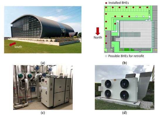
Figure 2.
Case study: (a) building, (b) layout of the installed boreholes, (c) new heat pump, (d) air-condenser.
The heating and cooling demand of the building was originally provided with a double circuit, four compressors R407C water-to-water heat pump coupled to 16 boreholes, 95 m long and 7 m apart and arranged as shown in Figure 2b. The operation of the system has shown, over the years, a progressive increase in the probes’ fluid temperature, also with peaks, as shown in Figure 3a, where the entering fluid temperature to the heat pump measured by the building management system is shown, as well as the annual minimum and maximum external air temperatures. As can be seen, the minimum value of the outlet fluid temperature from boreholes increases from about 8 °C in 2005 to about 13 °C in 2013; whereas at the site, the external air temperature ranged between about −6 °C and 35 °C over 11 years. During the summer of 2013, the maximum value of the entering fluid temperature to the heat pump was about 44 °C and the value of the inlet fluid temperature to the borehole was about 48 °C (Figure 3b). These values were very different from design conditions that were set between 30 and 35 °C. Under these severe conditions, there was also occasional deficiency in refrigeration capacity. For these reasons and also because of obsolescence of the heat pump it was decided to proceed with the retrofit.
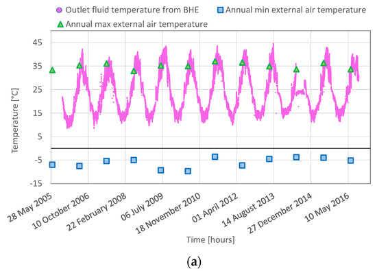
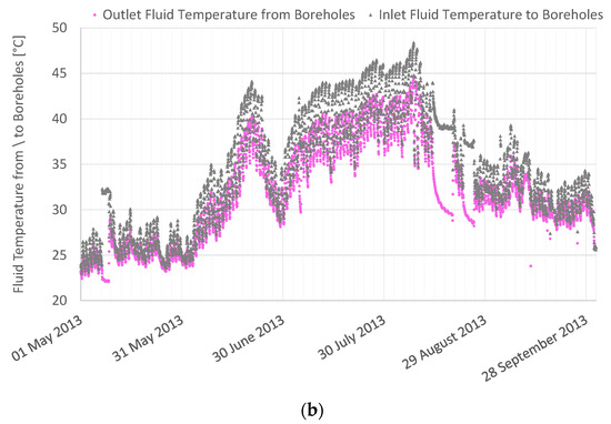
Figure 3.
Measured hourly fluid temperature: (a) outlet fluid temperature from borehole heat exchangers with annual minimum and maximum external air temperatures, (b) inlet and outlet fluid temperature to/from borehole heat exchangers from May to September 2013.
In 2017, following the analysis described below, the heat pump was changed with a new machine (Figure 2c) coupled to both the boreholes and an air-condenser (Figure 2d) to be used only during the cooling season; in summer, the heat pump can switch between the ground heat exchangers and air-condenser without a secondary loop, thus no additional compressors or pumps are present. A scheme of the layout of the new hybrid heat pump in heating and cooling mode is shown in Figure 4. In particular, in cooling mode, the heat pump can use the water-condenser coupled to the borehole heat exchangers (Figure 4a) or, alternatively, the air-condenser (Figure 4b); the switch between the borehole heat exchangers and the air-condenser is controlled via an appropriate control strategy based on the external air temperature. In heating mode, only the ground through the borehole heat exchangers is used by the heat pump as a heat source (Figure 4c).
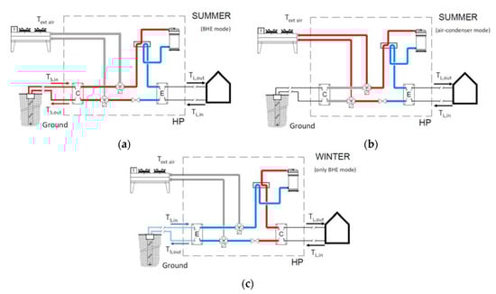
Figure 4.
Scheme of the new hybrid heat pump: (a) operation in cooling mode using borehole heat exchangers; (b) operation in cooling mode using air-condenser; (c) operation in heating mode using borehole heat exchangers.
The characteristics of both old and new heat pumps are reported in Table 1. The heat pump is used for both space heating and cooling as well as for the air handling unit; the supply set-point fluid temperature is constant and equal to 35 °C in heating mode, whereas two different values are set in cooling mode—i.e., 7 °C in daytime (i.e., when the air handling unit is switched on) and 15 °C at night time (when only the TAB system works), to improve the energy efficiency.

Table 1.
Characteristics of the old and new heat pump.
The borehole heads are buried at about 1 m beneath the ground surface. Double U-tube heat exchangers are installed inside the boreholes and the outside (inside) diameter of the pipe is 32 mm (26 mm); the borehole diameter is 140 mm. The two U-tubes inside each borehole heat exchanger are coupled in parallel. The heat-carrier fluid inside the ground heat exchangers is pure water with a total constant mass flow rate equal to 5.56 kg/s. On the building side, the total mass flow rate of heat-carrier fluid (i.e., water) is equal to 6.10 kg/s. The fluid mass flow rates in the loops were considered constant over the simulation time; clearly when the GSHP is switched off, CaRM calculates the temperature in each thermal node of the domain according to the transient heat balance, therefore the thermal history is taken into account. An equivalent ground layer was used to carry out the simulations: the mean weighted thermal conductivity was 1.9 W/(m K) and the volumetric heat capacity was 2.24 MJ/(m3 K). The undisturbed ground temperature was assumed to be 14 °C. The groundwater flow effect at the site was considered negligible.
The heating and cooling demands of the building were calculated by means of the EnergyPlus tool over eleven years using real weather data provided by the regional environmental agency ARPAV [37] for the weather station of Legnaro (at about ten kilometers from the building). Figure 5 shows the calculated annual energy loads of the heat pump from 2005 to 2016. As can be observed, the ratio between the annual heating and cooling energy demand ranges from 0.65 initially, to 0.49 at the end of the considered period. This confirms that the building’s annual load profile is cooling dominant. The interested reader will find additional details on the building thermal load calculation in the reference [38].
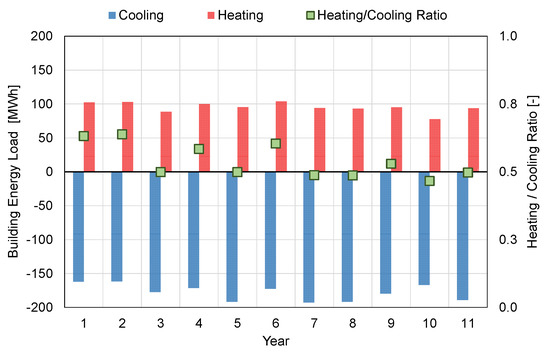
Figure 5.
Calculated annual thermal load of the building from 2005 to 2016 and heating to cooling energy demand ratio.
Table 2 and Table 3 report the coefficients of the old and new heat pump, as well as the air-condenser, according to the equations shown in Section 2; these coefficients were calculated making use of data from the manufacturers.
Table 2.
Coefficients for the water-to-water heat pump models.
Table 3.
Coefficients for the air-condenser model.
3.2. Computer Simulations
The building load profile was calculated via EnergyPlus over 22 years (from year 2005 to year 2026). In April 2017, the old ground source heat pump had to be changed, and different solutions were investigated. As a consequence, the model implemented in the CaRM tool considers this change throughout time without losing the thermal footprint due to the previous history. Moreover, during the period between 2006 and 2017, real weather data for the considered location were applied as boundary conditions, while for the coming years, the test reference year (TRY) of Padova [39] was considered.
The following scenarios were considered:
- ▪
- Scenario 1—Baseline: the old heat pump and the actual borehole field were simulated throughout the time;
- ▪
- Scenario 2—Retrofit with new Heat Pump: the change of the water-to-water heat pump was implemented from April 2017, maintaining the actual borehole field;
- ▪
- Scenario 3—Retrofit with new hybrid Heat Pump: similar to Scenario 2 but in the cooling period the air-condenser chiller was also simulated;
- ▪
- Scenario 4—Retrofit with new Heat Pump and an extended BHE: similar to Scenario 2 but two new boreholes with the same characteristics are added (the maximum allowed by the size of the property, (Figure 2b)).
In Scenario 3, a suitable control strategy was adopted to choose the best heat sink (ground or external air) so as to increase the energy efficiency of the entire system. Specifically, when the external air temperature was lower than 25 °C, the air-condenser was switched on, whereas when it was higher than that temperature the condenser of the heat pump was switched to the ground loop. This control strategy was investigated in depth in a previous work [40].
All these scenarios were analyzed to check the efficacy to decrease the thermal drift of the ground temperature. The purpose of this comparative analysis was to provide the designers with a wide range of results so that they could also understand the effects of an inaccurate system design.
4. Results and Discussion
In this section, the thermal behavior of the retrofit solutions is investigated, and the main results of the computer simulations are summarized. In particular, the comparison was carried out in terms of outlet fluid temperature from the borehole heat exchangers, seasonal energy efficiency and annual electrical consumption of the heat pump.
Figure 6 outlines the mean monthly outlet fluid temperature from the borehole heat exchangers. In detail, Figure 6a shows the outlet fluid temperature from the 16 ground heat exchangers throughout 22 simulated years if the original GSHP is considered (Scenario 1). Although the computer simulations were carried out with hourly time step, the profiles plot the mean monthly outlet fluid temperature in order to have a better readability along the time. In the first part of the figure, the measured values from the building management system (BMS) are also reported. As can be seen, the high unbalanced building load profile (cooling dominant) involves the growing trend of the mean monthly outlet fluid temperature from 2005 to 2017. During this period, the real weather data of the location are used for the simulation of both the building and GSHP system in CaRM. From 2017 to 2026, the thermal drift of the ground temperature is lower than the previous period and, in addition, the profile is more stable; this is due to the use of the test reference year of Padova [39] as a climate boundary condition. As can be seen in Figure 6, the trend of simulation results is in good agreement with the measured values from the building management system for the period 2005–2017; however, higher differences can be observed during the summer. The fluid temperatures were measured at the heat pump, whereas the simulated values are calculated at the top of the boreholes without considering the horizontal piping.
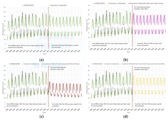
Figure 6.
Mean monthly outlet fluid temperature from the borehole heat exchangers: measured values from 2006 to 2017; simulated values in (a) Scenario 1, (b) Scenario 2, (c) Scenario 3, (d) Scenario 4.
Figure 6b shows the profile of the mean monthly outlet fluid temperature from the borehole heat exchangers when the old heat pump is changed with the new water-to-water heat pump (Scenario 2). In this case, only the heat pump is changed and the other boundary conditions are identical to Scenario 1 (Figure 6a). As can be seen, the difference with the baseline is negligible; some improvement can be found due to the better performance of the new heat pump.
When the new concept of the hybrid heat pump is considered (Scenario 3), the difference compared to the baseline is clearer (Figure 6c). In this case, during the cooling period the heat pump can switch between the air-condenser and the borehole heat exchangers. The control strategy is set on the dry-bulb external air temperature. The ground thermal load is lower than that in the previous cases and this involves low fluid temperature to exchange the required heat transfer rate. Figure 6d shows the results when the water-to-water heat pump was changed in 2017 and other two boreholes were added to the existing field (Scenario 4). This solution involves an improvement compared to the baseline (Scenario 1) and Scenario 2 but, as it can be seen, the benefit is limited: the maximum mean monthly temperature moves from 34 °C to 32 °C. In fact, the ground temperature is affected from the previous operating conditions and the thermal performance of the new borehole field cannot change in the short-term.
The fluid temperatures shown in Figure 6 clearly depend on the heat extraction–injection rate exchanged with the ground. This value is outlined in Figure 7 for each scenario. As expected, in Scenario 3 the heat energy load on the ground is quite balanced, while in other cases a great unbalance occurs involving the thermal drift of the ground temperature. Figure 8 shows hourly profiles of the heat load injected into the ground and rejected to the external air during the 15 and 16 July of the last simulated year in Scenario 3; this figure highlights the control strategy set in this solution—as can be seen, when the external air temperature is lower (higher) than 25 °C, the heat pump switches on the air-condenser (borehole heat exchangers).
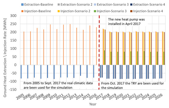
Figure 7.
Ground heat extraction–injection rate in each simulated scenario.
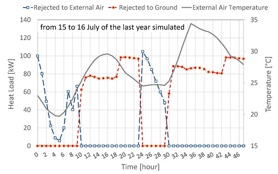
Figure 8.
Hourly profiles of the heat load rejected to the ground and the external air during the 15 and 16 July of the last simulated year in Scenario 3.
Figure 9 shows the seasonal energy efficiency of the heat pump in each case analyzed. This value was calculated as ratio between the supplied energy to the building and the electrical consumption of the heat pump. The other mechanical systems (ground loop circulation pump and fans of the air-condenser) were not considered in this comparative evaluation; the circulation pump of the ground loop has constant speed and its electrical power is about 1.7 kW, while the air-condenser’s fans have variable speed with total nominal electrical power of about 900 W. The electrical consumption of auxiliary systems may not be negligible, however being a comparative analysis and considering the mentioned powers these contributions were not taken into account. Figure 9a outlines the effect of the thermal drift of the ground temperature in Scenario 1; the seasonal energy efficiency in heating mode (SCOP) increases, whereas the seasonal energy performance in cooling mode (SEER) decreases due to the increase in the ground temperature. The SEER value started from about 4.5 in 2005 and moved to about 3.7 in 2016. In the second period from 2017 to 2026, the profile was more stable because the test reference year was used. The new heat pump presents better performance, especially in heating mode (Scenario 2) (Figure 9b). With the hybrid heat pump (Scenario 3) (Figure 9c), the energy performance fully improves; as was expected, the trend of the SCOP profile changes because part of the cooling load is rejected to external air, consequently the ground temperature decreases over time. SEER values are high because the control strategy is optimized to switch between external air and ground loop at 25 °C—when the external air temperature is lower than 25 °C the heat pump moves on the air-condenser, when it is higher than 25 °C, the heat load is injected into the ground. When the solution is only based on the GSHP (Scenario 2 and Scenario 4), the seasonal energy performance improvement is low due to the previous operating conditions and unbalanced load profile.
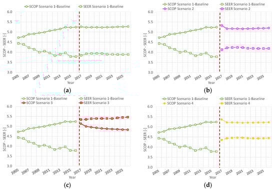
Figure 9.
Seasonal energy efficiency of the heat pump: simulated values in (a) Scenario 1, (b) Scenario 2, (c) Scenario 3, (d) Scenario 4.
Figure 10 outlines the annual electrical consumption of the heat pump during the whole period. The hybrid solution with the air-condenser is the most convenient; in addition, it can be seen that the electrical consumption of the heat pump coupled with the air-condenser (in cooling mode) is about one third of the total value.
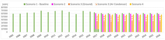
Figure 10.
Annual electrical consumption of the heat pump for each simulated scenario.
Table 4 reports the initial and installation costs for each retrofit scenario. For the installation of two new borehole heat exchangers to the existing borehole field, an average unit cost of 44 EUR/m was considered; it is necessary to also add the cost for the site preparation for drilling operation that was estimated to be about EUR 2000. All these costs (VAT not included) were evaluated according to the Italian market, considering several operators in the field.
Table 4.
Retrofit solutions costs.
From the electricity bills of the building, the average price of the electricity is 0.15 EUR/kWhel (excluding VAT). As a consequence, the annual cost of the electricity consumption for each retrofit scenario can be evaluated considering the results of the previous simulations. Figure 11 reports the annual electricity cost for Scenarios 2, 3 and 4 from 2018 to 2026 due to heat pump consumption. The total operation costs from 2018 to 2026 are: EUR 78.959 for Scenario 2, EUR 70.945 for Scenario 3, and EUR 76.013 for Scenario 4. The operation cost savings of Scenarios 3 and 4 compared to Scenario 2 are about 10% and 4%, respectively. The hybrid solution (Scenarios 3) shows the lower annual cost for operating conditions, with an economic saving of about 890 EUR/year compared with Scenario 2 and about 560 EUR/year compared with Scenario 4 (i.e., the ground source heat pump with two additional boreholes). Considering in any case necessary the change in the machine (Scenario 2) and taking into account the differences between the initial costs reported in Table 4, a simple pay-back time of the hybrid solution of Scenario 3 compared to Scenario 2 is about 12 years, while the pay-back time of Scenario 4 compared to Scenario 2 is about 31 years. Additionally, evaluating the benefit of lowering the ground temperature—with all things considered—the solution of Scenario 3 was the one adopted.
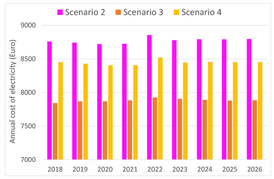
Figure 11.
Annual electricity cost of the heat pump in simulated retrofit solutions from 2018 to 2026.
5. Conclusions
The design of the air-conditioning system is an important issue because it affects the proper operation and energy consumption of the building. This is true for each system, but in a ground source heat pump system, it is fundamental due to the high initial investment cost, especially for borehole drilling. However, even though the designer adopted the best solution and was meticulous in his assumptions, the boundary conditions of the system could change over the years. In a ground source heat pump, the energy unbalance on the ground heat exchangers causes a decrease or increase in the ground temperature (thermal drift), which affects the system’s energy efficiency and operating conditions. In these cases, a retrofitting can be necessary to assure low energy consumption and high environmental quality to the users.
In this work, some retrofit solutions of an existing ground source heat pump system in a cooling dominant office building located in Italy were analyzed. The system is one of the first installations of a ground source heat pump in Italy and after about ten operating years showed the effect of the decrease in the energy efficiency due to the heat unbalance on the ground side. To solve this inconvenience, a new hybrid system based on a dual heat sink (both ground and external air) was installed. However, other solutions were also analyzed—the simple change in the heat pump and the installation of additional borehole heat exchangers. All the retrofit solutions were simulated by means of a numerical model (CaRM), capable of simultaneously considering the heat pump and the borehole field, which was integrated with other important modules. In fact, the current tools do not allow for the change in the number of borehole heat exchangers over time; therefore, the numerical model was modified to support this option.
With the hybrid heat pump, thanks to the adopted control strategy based on the external air temperature, the thermal balance on the ground side was achieved, limiting the thermal drift of the ground temperature. Consequently, the hybrid solution showed the best results in terms of energy efficiency and operation cost saving (about-10%) compared to the common ground source heat pump. In addition, the installation cost of the hybrid heat pump was only about 2% higher than that of the solution with additional boreholes.
To design a ground source heat pump, the estimation of the thermal loads over time is fundamental because the ground surrounding the borehole heat exchangers presents a time constant on the order of years. This study highlights the effects of the energy unbalance on ground heat exchangers after about ten years in a real application. The analysis presented in this work aims to be for designers a benchmark of retrofit of an existing ground source heat system. Moreover, the new developments of the model can be also considered by researchers. In fact, the paper remarks the importance of simulation models that can also help the designers after the design phase to maintain the good performance of the systems, especially for ground source heat pumps where the analysis has to be carried out over several years.
Author Contributions
Conceptualization, methodology, modelling and computer simulations, writing: A.Z.; modelling and computer simulations, methodology and writing: D.G.; supervision, methodology and writing: R.Z., P.P., E.P., J.V., M.D.C. and G.E. All Authors analyzed the results, providing technical and theoretical support, reviewed and approved the final version. All authors have read and agreed to the published version of the manuscript.
Funding
This research received no external funding.
Acknowledgments
The authors are highly grateful to HiRef S.p.A. for providing the full set of performance data concerning the water-to-water heat pump and air condenser examined in this work.
Conflicts of Interest
The authors declare no conflict of interest.
Abbreviations
| Nomenclature | |
| a | surface absorptance |
| COP | coefficient of performance (W/W) |
| EER | energy efficiency ratio (W/W) |
| h | convection heat transfer coefficient (W/(m2 K)) |
| L | length (m) |
| P | power (W) |
| PLR | part load ratio |
| Q | heating capacity of the heat pump (W) |
| r | radius (m) |
| SCOP | seasonal COP (W/W) |
| SEER | seasonal EER (W/W) |
| T | temperature (K) |
| Tref | reference temperature (K) |
| volumetric flow rate (m3/s) | |
| Greek Symbols | |
| ε | emissivity (-) |
| Subscripts | |
| avail | available |
| b | borehole |
| c | cooling |
| cond | condenser |
| cw | chilled water |
| e | entering |
| el | electrical |
| ext | external |
| g | ground |
| h | heating |
| in | inlet |
| l | leaving |
| L | load side |
| min | minimum |
| nom | nominal |
| S | source side |
| Abbreviations | |
| ASHP | Air Source Heat Pump |
| BHE | Borehole Heat Exchanger |
| GSHP | Ground Source Heat Pump |
| TRY | Test Reference Year |
| Min | Minimum |
| Max | Maximum |
References
- European Parliament. European Parliament resolution of 14 March 2019 on Climate Change—A European Strategic Long-Term Vision for a Prosperous, Modern, Competitive and Climate Neutral Economy in Accordance with the Paris Agreement (2019/2582(RSP). Available online: https://www.europarl.europa.eu/doceo/document/TA-8-2019-0217_EN.html (accessed on 28 August 2020).
- European Parliament. European Parliament Resolution of 15 January 2020 on the European Green Deal (2019/2956(RSP). Available online: https://www.europarl.europa.eu/doceo/document/TA-9-2020-0005_EN.html (accessed on 28 August 2020).
- International Energy Agency (IEA). Global Status Report for Buildings and Construction 2019; IEA: Paris, France, 2019; Available online: https://www.iea.org/reports/global-status-report-for-buildings-and-construction-2019 (accessed on 1 June 2020).
- Aresti, L.; Christodoulides, P.; Florides, G. A review of the design aspects of ground heat exchangers. Renew. Sustain. Energy Rev. 2018, 92, 757–773. [Google Scholar] [CrossRef]
- Ferrara, M.; Sirombo, E.; Monti, A.; Fabrizio, E.; Filippi, M. Influence of envelope design in the optimization of the energy performance of a multi-family building. Energy Procedia 2017, 111, 308–317. [Google Scholar] [CrossRef]
- Atam, E.; Helsen, L. Ground-coupled heat pumps: Part 1—Literature review and research challenges in modeling and optimal control. Renew. Sustain. Energy. Rev. 2016, 54, 1653–1667. [Google Scholar] [CrossRef]
- Cui, Y.; Zhu, J.; Twaha, S.; Chu, J.; Bai, H.; Huang, K.; Chen, X.; Zoras, S.; Soleimani, Z. Techno-economic assessment of the horizontal geothermal heat pump systems: A comprehensive review. Energy Convers. Manag. 2019, 191, 208–236. [Google Scholar] [CrossRef]
- Esen, H.; Inalli, M.; Esen, M. A techno-economic comparison of ground-coupled and air-coupled heat pump system for space cooling. Build. Environ. 2007, 42, 1955–1965. [Google Scholar] [CrossRef]
- Lu, Q.; Narsilio, G.A.; Aditya, G.R.; Johnston, I.W. Economic analysis of vertical ground source heat pump systems in Melbourne. Energy 2017, 125, 107–117. [Google Scholar] [CrossRef]
- Sarbu, I.; Sebarchievici, C. General review of ground-source heat pump systems for heating and cooling of buildings. Energy Build. 2014, 70, 441–454. [Google Scholar] [CrossRef]
- American Society of Heating, Refrigerating, and Air-Conditioning Engineers (ASHRAE). ASHRAE Handbook: HVAC Applications, Geothermal Energy; ASHRAE: Atlanta, GA, USA, 2011; Chapter 34. [Google Scholar]
- Kavanaugh, S.P.; Rafferty, K. Ground-source Heat Pumps—Design of Geothermal System for Commercial and Institutional Buildings; ASHRAE Applications Handbook: Atlanta, GA, USA, 1997. [Google Scholar]
- Spitler, J.D. GLHEPRO a design tool for commercial building ground loop heat exchangers. In Proceedings of the Fourth International Heat Pumps in Cold Climates Conference, Aylmer, QC, Canada, 17–18 August 2000. [Google Scholar]
- Hellström, G.; Sanner, B. Earth Energy Designer: Software for Dimensioning of Deep Boreholes for Heat Extraction; Department of Mathematical Physics, Lund University: Lund, Sweden, 1994. [Google Scholar]
- Gehlin, S. Thermal Response Test: Method, Development and Evaluation. Ph.D. Thesis, Lulea University of Technology, Lulea, Sweden, 2002. [Google Scholar]
- Austin, W.A. Development of an In Situ System for Measuring Ground Thermal Properties. Master’s Thesis, Oklahoma State University, Stillwater, OK, USA, 1998. [Google Scholar]
- Pasquier, P.; Zarrella, A.; Marcotte, D. A multi-objective optimization strategy to reduce correlation and uncertainty for thermal response test analysis. Geothermics 2019, 79, 176–187. [Google Scholar] [CrossRef]
- U.S. Department Of Energy. Engineering Reference Manual. In EnergyPlus V8.5. 2016. Available online: https://energyplus.net/ (accessed on 28 August 2020).
- Eskilson, P. Thermal Analysis of Heat Extraction Boreholes. Ph.D. Thesis, Lund University, Department of Mathematical Physics, Lund, Sweden, 1987. [Google Scholar]
- Eskilson, P. Superposition Borehole Model. Manual for Computer Code; Lund University, Department of Mathematical Physics: Lund, Sweden, 1986. [Google Scholar]
- Cimmino, M.; Bernier, M. Preprocessor for the generation of g-functions used in the simulation of geothermal systems. In Proceedings of the 13th Conference of International Building Performance Simulation Association, Chambéry, France, 26–28 August 2013; pp. 2675–2682. [Google Scholar]
- Pasquier, P.; Zarrella, A.; Labib, R. Application of artificial neural networks to near-instant construction of short-term g-functions. Appl. Therm. Eng. 2018, 143, 910–921. [Google Scholar] [CrossRef]
- Starace, G.; Congedo, P.M.; Colangelo, G. Horizontal heat exchangers for GSHPs efficiency and cost investigation for three different applications. In Proceedings of the 18th International Conference on Efficiency, Cost, Optimization, Simulation and Environmental Impact of Energy Systems, ECOS, Trondheim, Norway, 20–22 June 2005; pp. 1443–1450. [Google Scholar]
- Javed, S.; Ornes, I.R.; Myrup, M.; Dokka, T.H. Design optimization of the borehole system for a plus-Energy kindergarten in Oslo, Norway. Archit. Eng. Des. Manag. 2019, 15, 181–195. [Google Scholar] [CrossRef]
- Qi, Z.S.; Gao, Q.; Liu, Y.; Yan, Y.Y.; Spitler, J.D. Status and development of hybrid energy systems from hybrid ground source heat pump in China and other countries. Renew. Sustain. Energy Rev. 2014, 29, 37–51. [Google Scholar] [CrossRef]
- Soni, S.K.; Pandey, M.; Bartaria, V.N. Ground coupled heat exchangers: A review and applications. Renew. Sustain. Energy Rev. 2015, 47, 83–92. [Google Scholar] [CrossRef]
- Zhijian, L.; Wei, X.; Xue, Z.; Cheng, Q.; Xi, C. Feasibility and performance study of the hybrid ground-source heat pump system for one office building in Chinese heating dominated areas. Renew. Energy 2017, 101, 1131–1140. [Google Scholar] [CrossRef]
- Ruiz-Calvo, F.; Montagud, C.; Cazorla-Marín, A.; Corberán, J.M. Development and Experimental Validation of a TRNSYS Dynamic Tool for Design and Energy Optimization of Ground Source Heat Pump Systems. Energies 2017, 10, 1510. [Google Scholar] [CrossRef]
- Corberán, J.M.; Cazorla-Marin, A.; Marchante-Avellaneda, J.; Montagud, C. Dual Source Heat Pump, a High Efficiency and Cost-Effective Alternative for Heating, Cooling and DHW Production. Int. J. Low-Carbon Technol. 2018, 13, 161–176. [Google Scholar] [CrossRef]
- Pacchiega, C.; Fausti, P. A study on the energy performance of a ground source heat pump utilized in the refurbishment of an historical building: Comparison of different design options. In Proceedings of the Climamed 2017—Mediterranean Conference of HVAC: Historical Buildings Retrofit in the Mediterranean Area, Matera, Italy, 12–13 May 2017. [Google Scholar]
- Chiasson, A.D.; Yavuzturk, C.; Talbert, W.J. Design of School Building HVAC Retrofit with Hybrid Geothermal Heat-Pump System. J. Archit. Eng. 2004, 10, 103–111. [Google Scholar] [CrossRef]
- Zarrella, A.; Zecchin, R.; De Rossi, F.; Emmi, G.; De Carli, M.; Carnieletto, L. Analysis of a double source heat pump system in a historical building. In Proceedings of the 16th Conference of International Building Performance Simulation Association, Rome, Italy, 2–4 September 2019. [Google Scholar]
- Hang, W.; Xinhua, X.; Anbang, L.; Tian, Y.; Wenjie, G. A wet-bulb temperature-based control method for controlling the heat balance of the ground soil of a hybrid ground-source heat pump system. Adv. Mech. Eng. 2017, 9, 1–12. [Google Scholar] [CrossRef]
- Zarrella, A.; Pasquier, P. Effect of axial heat transfer and atmospheric conditions on the energy performance of GSHP systems: A simulation-based analysis. Appl. Therm. Eng. 2015, 78, 591–604. [Google Scholar] [CrossRef]
- Tang, C.C. Modeling Packaged Heat Pumps in a Quasi-Steady State Energy Simulation Program; Oklahoma State University: Stillwater, OK, USA, 2005. [Google Scholar]
- Currò Dossi, F.; De Carli, M.; Del Bianco, R.; Fellin, F.; Tonon, M.; Zecchin, R. A pilot project for a low energy building equipped with thermal slabs, heat pump and ground heat storage. In Proceedings of the 8th International IBPSA Conference 2003, Eindhoven, The Netherlands, 11–14 August 2003. [Google Scholar]
- ARPAV Agenzia Regionale per la Prevenzione e per la Protezione Ambientale del Veneto. 2017. Available online: http://www.arpa.veneto.it (accessed on 1 April 2017).
- Zarrella, A.; Zecchin, R.; Pasquier, P.; Guzzon, D.; De Carli, M.; Emmi, G.; Quaggia, M. A comparison of numerical simulation methods analyzing the performance of a ground-coupled heat pump system. Sci. Technol. Built Environ. 2018, 24, 502–512. [Google Scholar] [CrossRef]
- Comitato Termotecnico Italiano CTI. Test Reference Years for Italian Regions. Available online: https://www.cti2000.it/ (accessed on 1 September 2018).
- Zarrella, A.; Zecchin, R.; Pasquier, P.; Guzzon, D.; Ciantia, M.; De Carli, M.; Emmi, G. A double source heat pump: A case study. In 2nd IGSHPA Research Track; IGSHPA: Stockholm, Sweden, 2018. [Google Scholar] [CrossRef]


Publisher’s Note: MDPI stays neutral with regard to jurisdictional claims in published maps and institutional affiliations. |
© 2020 by the authors. Licensee MDPI, Basel, Switzerland. This article is an open access article distributed under the terms and conditions of the Creative Commons Attribution (CC BY) license (http://creativecommons.org/licenses/by/4.0/).