Article

Systematic Experimental Investigation on In-Situ Self-Adaptive Sealing Property of Composite Pressure-Activated Sealant for Curing Minor Tubular Leaks

1
School of Petroleum Engineering & Environment, Zhejiang Ocean Univerisity, Zhoushan 316022, China
2
Unconventional Oil and Gas Science and Technology Research Institute, China University of Petroleum (Beijing), Beijing 102249, China
3
Institute of Exploration Techniques, CAGS, Langfang 065000, China
4
Beijing Research Center of CNOOC (China) Co., Ltd., Beijing 100027, China
5
Hubei Collaborative Innovation Center for Unconventional Oil and Gas, College of Petroleum Engineering, Yangtze University, Wuhan 430100, China
6
School of Chemistry and Chemical Engineering, Queen’s University Belfast, Belfast BT95AG, UK
*
Authors to whom correspondence should be addressed.
Energies 2020, 13(21), 5597; https://doi.org/10.3390/en13215597
Submission received: 22 September 2020 / Revised: 24 October 2020 / Accepted: 26 October 2020 / Published: 26 October 2020
(This article belongs to the Special Issue Advances in Drilling Fluid Technology)

Abstract

:
Curing minor leaks and restoring the integrity of a wellbore in a safe and economical way is always challenging in oil and gas production. In this work, a composite pressure-activated sealant, combined with liquid and solid sealing materials, was prepared via the demulsification approach. The structure, morphology, and size distribution of key particulates in the sealant were examined, and the in-situ self-adaptive sealing property was examined with a specially design dynamic sealing detector. The results indicated that the pressure-activated sealant was a multi-dispersed phase system, and the dispersed colloid particles were regular in shape and had a narrow size distribution of 300–400 μm. The solid sealing materials were introduced to construct a composite pressure-activated sealant, and the sealing capability can be markedly reinforced by cooperativity of liquid and solid sealing materials. A mechanochemical coupling model was put forward to rationalize the dynamic sealing process. Finally, such sealant system was employed in a certain offshore gas well with sustained casing pressure to verify its applicability in minor defect repairs.

1. Introduction

Seal invalidation and joint leaks are usually inevitable, and they tend to become more complicated and severe as oil and gas production progress, which can cause serious economic losses and operation risks to the environment and integrity management. Thus, curing leak failure and restoring wellbore integrity have been an important goal in the petroleum industry, including both experimental and applied approaches, due to their fundamental role in determining the sustainable production of wells, especially for marginal and offshore wells.
As the most traditional repair methods, mechanical repairs [1] and chemical sealants [2,3,4,5] have been extensively studied over the past few decades. Although these conventional methods have proven useful in curing leaks and restoring the integrity of the wellbore, there are various limitations to on-site operations. For example, the mechanical repairs require expensive remotely operated vehicle (ROV) operations and rig workovers, which can lead to large risks to production, safety, and the environment. Furthermore, in general, the injectable chemicals are sensitive to the external environment and can be chemically activated and consolidated in non-target sections. Therefore, developing a novel alternative to conventional repair technology is a challenging and popular goal.
In the past few decades, a unique pressure-activated sealant consisting of a super-saturated mixture of short-chain polymers, monomers, and polymerizing chemicals in a carrier fluid has been under active investigation and application due to its safe and economic properties [6,7,8]. Such a specifically designed sealant is capable of remaining fluid in the migration pathways, and only at the point of differential pressure at a leak site, will the sealing reaction occur and bridge across the leak. This pressure-activated sealant is analogous to blood coagulating at a cut, and its application as a biomimetic self-adapting seal in defective sections as diverse as cement channels, casing leaks, tubing leaks, and the wellhead hanger has been widely reported and reviewed [9,10,11]. For example, Rodrigues et al. [12] reported the application of a pressure-activated sealant in the deep water Campos Basin. They pointed out that the sealant treatments were more favorable to peoples’ health and safety and to the environment, and they also emphasized that the plugging capabilities and longevity of the sealant technology needed to be further studied to enlarge the sealant’s application. Rusch et al. [13] reported on the component characteristics of the pressure-activated sealant and defined its particulate size to distinguish it from conventional particulate sealants. In addition, they validated the sealant’s application in a new field of curing leaks in gas transmission pipelines. Previous studies have mainly focused on the repairs of minor leaks with high surface area to leak area ratios. Recently, Guo et al. [14] and Xing et al. [15] explored formula of pressure-activated sealants in detail, and they concluded that controlling the particulate size is very fundamental to expanding the sealant application. Consequently, the implication of the component particulates in the sealant reaction from the geometric characteristics to the dynamic sealing behavior needs to be clarified, which will also be useful information for the design and development of new sealants.
However, compared to the extensive field efforts, to our knowledge, far less attention has been paid to laboratory investigations on the sealing mechanism, sealant design, and seal evaluation of pressure-activated sealants. It is worth noting that not all leaks can be repaired using a pressure-activated sealant. Thus, one area of particular interest is the extension of sealing applications to different defects. In this paper, a unique kind of composite pressure-activated sealant containing liquid sealant and solid sealing materials was conceptually presented, and the sealing feature and adaptability of such specially designed sealant system were systematically investigated.

2. Materials and Methods

2.1. Materials

Carboxylated acrylonitrile butadiene rubber latex (XNBRL, commercial code, Shanghai Judao Chemicals Co., Shanghai, China), magnesium chloride (MgCl2, Jining Shanyuan Chemicals Co., Jining, China), and cetyl trimethyl ammonium chloride (1631, Henan Daochun Chemicals Co., Zhengzhou, China) were used without further purification. Acrylamide multipolymer (PLUS, commercial code,), organic silicon polymer (CES, commercial code,), calcium carbonate (CaCO3, 50 mesh), and sepiolite fiber were obtained from the Jingzhou Jiahua Technology Co., Jingzhou, China. It should be noted that XNBRL was used as the main agent to supply the active aggregation, while MgCl2, 1631, and CES were used as the activator, terminator, and deformer to control the coagulating reaction, respectively. These general agents were fundamental in regulating the particulate geometry of the sealants. In addition, solid sealing materials (i.e., the CaCO3 and fiber) were introduced as structure promoters to construct a composite pressure-activated sealant system, which cooperatively enhance the sealing capability.

2.2. Preparation of the Pressure-Activated Sealant

The general pressure-activated sealant and its composite system were prepared in laboratory. Note that, the preparation process of two sealants is similar, except that only solid sealing materials are introduced in the composite pressure-activated sealant.

2.2.1. General Pressure-Activated Sealant

A typical procedure for the preparation of a pressure-sensitive sealant is as follows (Figure 1). The PLUS solution (0.4 wt.%, 60 mL) was added to the main agent (XNBRL, 140 mL) in a 1-L three-neck flask equipped with a mechanical stirrer, an addition funnel, and a thermometer. Then, the solution was stirred at a speed of 2000 rpm at room temperature for 15 min. The mixture obtained was heated. When the temperature of the mixture reached 70 °C, the MgCl2 solution (20 wt.%, 40 mL) and CES (1 mL) were added dropwise in turn via the addition funnel while stirring at 70 °C for 10 min. Then, the stirring stopped for 20 min. The 1631 solution (30 wt.%, 11 mL) and the PLUS solution (0.4 wt.%, 80 mL) were poured into the flask in turn while stirring at 70 °C, and the stirring was maintained for 15 min to produce the general pressure-activated sealant. The type of pressure-activated sealant prepared here was designated as Sealant 0.

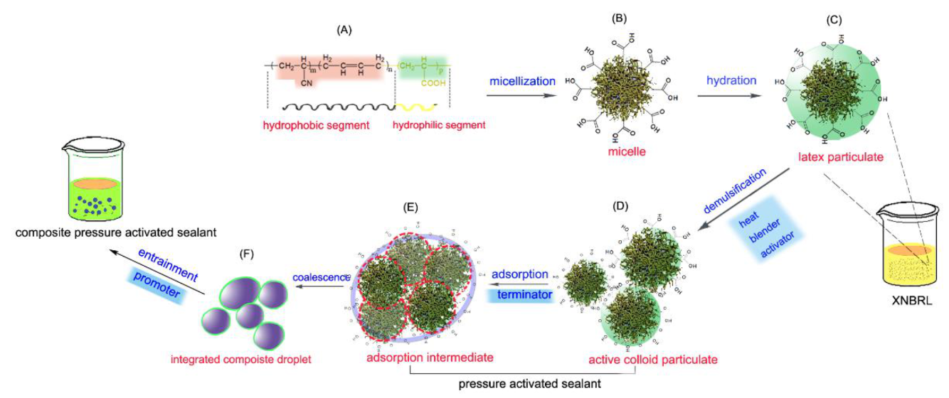
2.2.2. Composite Pressure-Activated Sealant

To prepare a composite pressure-activated sealant, two types of structure promoters, i.e., CaCO3 power (50 mesh, 2 g) and sepiolite fiber (length-diameter ratio of 160, 2 g), were separately added to Sealant 0 at 70 °C, while the mixture was blended at 1000 rpm. After 15 min, the blender was turned off, and the mixture was cooled to room temperature. The resulting suspension system was the composite pressure-activated sealant. Herein, the suspension system created by adding CaCO3 power is designated as Sealant I, and that created by adding both CaCO3 power and fiber is designated as Sealant II.

2.3. Measurements

Particulate morphology of sealant systems were examined, which should be meaning to improve the formula of sealant. Meanwhile, the sealing tests were conducted in laboratory and field to validate its availability in repairing different leaks. Systematic measurements related with mesostructure and sealing property can provide critical information on the structure-activity relationship of sealant.

2.3.1. Mesostructure Characterization

The morphology of the formed sealant system was observed using a VHX-6000 3D microscopic system with super depth of field. The particle size was further measured using a Master-Sizer 2000 laser particle size analyzer.

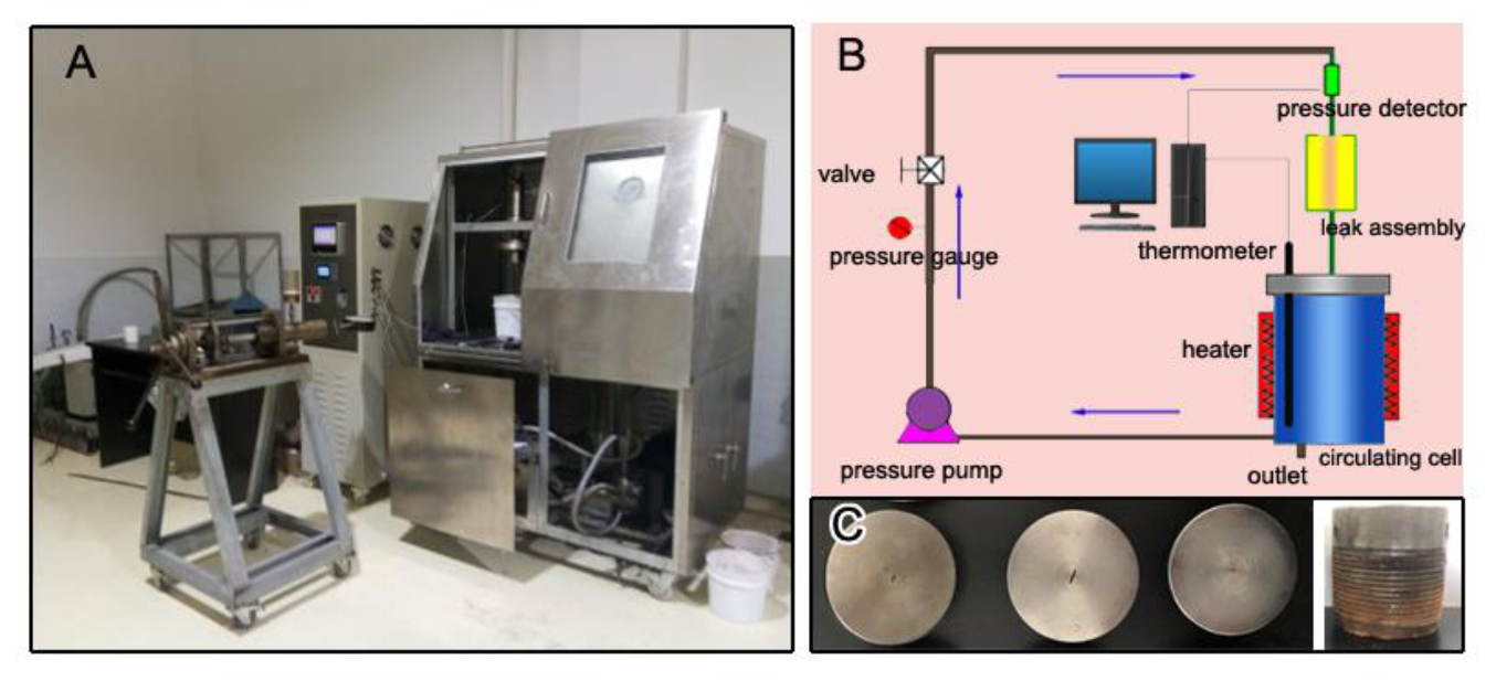
2.3.2. Dynamic Sealing Test

The dynamic sealing capabilities of the sealants were evaluated using a high temperature, high-pressure (HTHP) dynamic sealing detector (Figure 2), which was specially designed to examine the sealing property of pressure-activated sealants under different modeling conditions. To meet the extreme testing conditions, the HTHP dynamic sealing detector was run at 150 °C and 25 MPa. In addition, several seal defects were used to simulate typical field leakage situations, as shown in Figure 2. Herein, two kinds of defects, i.e., cracks and screw damage, were investigated. The length (L), width (W), and depth (D) parameters of the model cracks were 0.5 mm × 0.5 mm × 10 mm, 0.5 mm × 1.0 mm × 10 mm, and 0.6 mm × 2.0 mm × 10 mm, respectively.
Using the designed HTHP dynamic sealing detector, we effectively evaluated the dynamic sealing property based on the real-time pressure curve and the sealing solid formed through the leak path. First, the sealant was poured into a circulating cell, and the control valve was closed. Next, the sealant was heated to the required temperature, and then, the pressure pump was opened until the system’s pressure increased to the designed value. Subsequently, the control valve was opened to allow the system’s pressure to be transmitted to the sealing assembly. The real-time pressure variation data were recorded, which reflect the dynamic sealing process of the defects. Finally, the pressure pump was closed, and the sealing assembly was detached to observe the formed solid barrier.

2.4. Field Trial

A sustained casing pressure (SCP) problem has been detected in an onshore well in the South China Sea. To evaluate the applicability, the field trial was conducted on the SCP well and the prepared sealant was employed to repair the tubing leak using a platform injection technology, instead of traditional workover solutions.

3. Results and Discussion

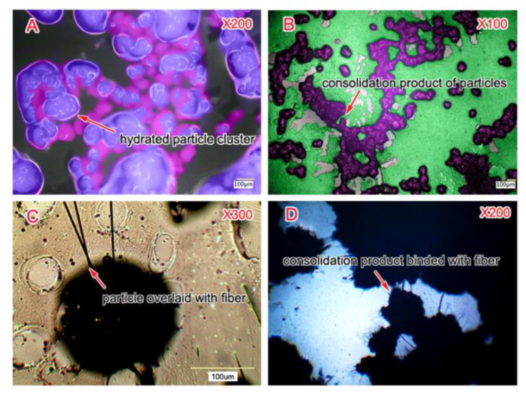
3.1. Mesostructure Analysis

It is generally known that the mesostructure of sealant composition is significant, which can, to a large extent, determine the sealing capability of sealant. Hence, morphology and size of particulates and their cluster in the sealant systems were examined.

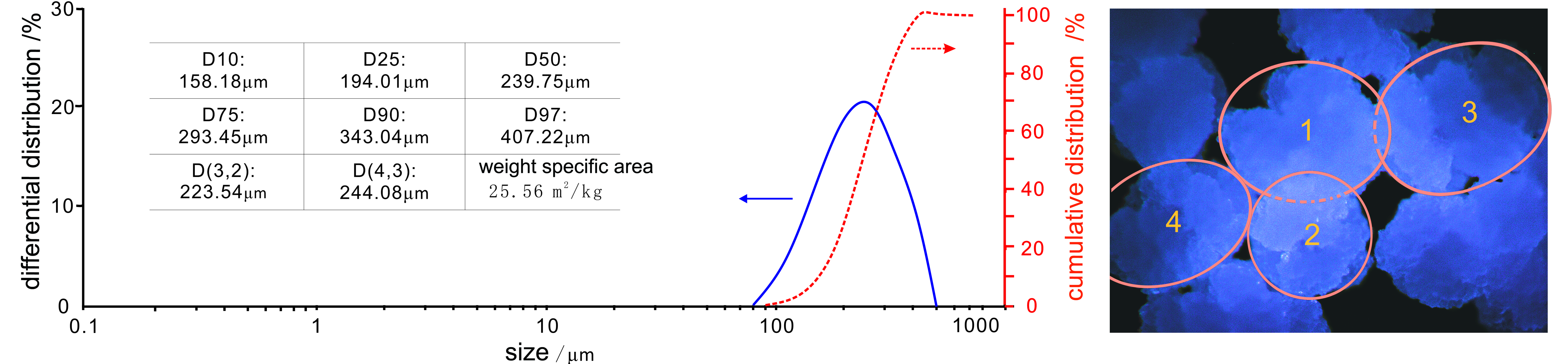
3.1.1. Mesostructure of the Coalescence Particulates

The composite sealant consists of a super-saturated mixture of 3D polymers, polymerizing chemicals, and a structure promoter in a carrier. These dispersed components were confirmed to significantly contribute to the curing capacity. Mesostructure analysis of the dispersed phase may shed light on the behavior of the self-adapting repair of a pressure-activated sealant.
The size distribution of the coalescence particles in the composite pressure-activated sealant is shown in Figure 3. What is also included in this figure is the analytic data for the mean sizes. The average size of the dispersed particles was about 239.75 μm in the obtained sealant system. There is only one peak in the 86–910 μm area of the differential distribution curve, reflecting a narrow size distribution (300–400 μm). The difference between the volume-surface mean size, D(3, 2), and the volume fourth moment mean size, D(4, 3), was as low as 20.54 μm. This further demonstrates the regular morphology of the coalescence particulates and the narrow distribution of the particle size. Of note is where this striking distribution characteristic of the dispersed particles appear, and in this case, the particle sizes mainly fell into the scope of the 1/9–1/3 crack size, which is very compatible with the crack size. Such a specific distribution of the particle size can facilitate the migration of the sealant particles into the leak’s geometry, which was also pointed out by Wang et al. [16], and would facilitate filling up and sealing defects.
Figure 3 also presents the morphology of the coalescence particles. The 3D structure of the particles is almost regular, which agrees with the results of the mean size. In addition, the surface of the particulates is tight and stacked due to the re-agglomeration of the latex particulates. This finding indicates that the particles may gradually grow up into the leak site, and the relevant 3D structure can become more integrated.

3.1.2. Mesostructure of the Coalescence Particulate Clusters

Figure 4 shows the morphology of a coalescence particle cluster in the composite pressure-activated sealant. As anticipated, the single particle morphology is almost spherical, and most of the microspheres are greater than 100 μm in size. These spherical particles tend to move into contact with each other to generate particle clusters. Furthermore, a thin hydration layer forms on the surface of the particle clusters, allowing for the formation of more stable composite droplets. The reason the hydrated layer is generated is that the external active base groups (e.g., carboxyl and amido group) of the 3D polymer can adsorb water molecules. The existence of a hydration layer effectively prevents the further aggregation of the particles into a colloid solid. Once the protective hydration membrane is broken down, re-agglomeration of particles can take place. Such plugging property is well consistent with that resulted from nanoscale acrylic resin/nano SiO2 composite (AR/SiO2), which can be enhanced by unique deformable behavior of core-shell structure [17]. Thus, the hydration layer surrounding the particulates is paramount to determining the sealant activation.
Figure 4B shows the morphology of the consolidation product obtained from the dehydrated particles. The protection film has broken down, enabling the robust consolidation of the coalescence particles. The formation of a flexible solid in the leak geometry is a self-assembly phenomenon of the dehydrated particles. Figure 4C shows an image of a single particle overlain with the sepiolite fiber. The fiber was clearly observed in the cross section of the flexible solid. This composite structure is very similar to the semi-flexible responsive brush of polymer particles reported by Minko [18], which is able to reinforce the end-to-end contact of particles, and improve the structural strength of a solid. It is believed that this consolidation structure overlain with fibers depends upon the interaction between the dehydrated particles and fiber, which facilitates the in-situ filling of the leak geometry.

3.2. Sealing Evaluation

Evaluation on seal property is crucial to determine the availability for the different sealant systems. Herein, three kinds of sealants, i.e., Sealant 0, Sealant I, and Sealant II, have been comparatively tested under the simulated leak conditions.

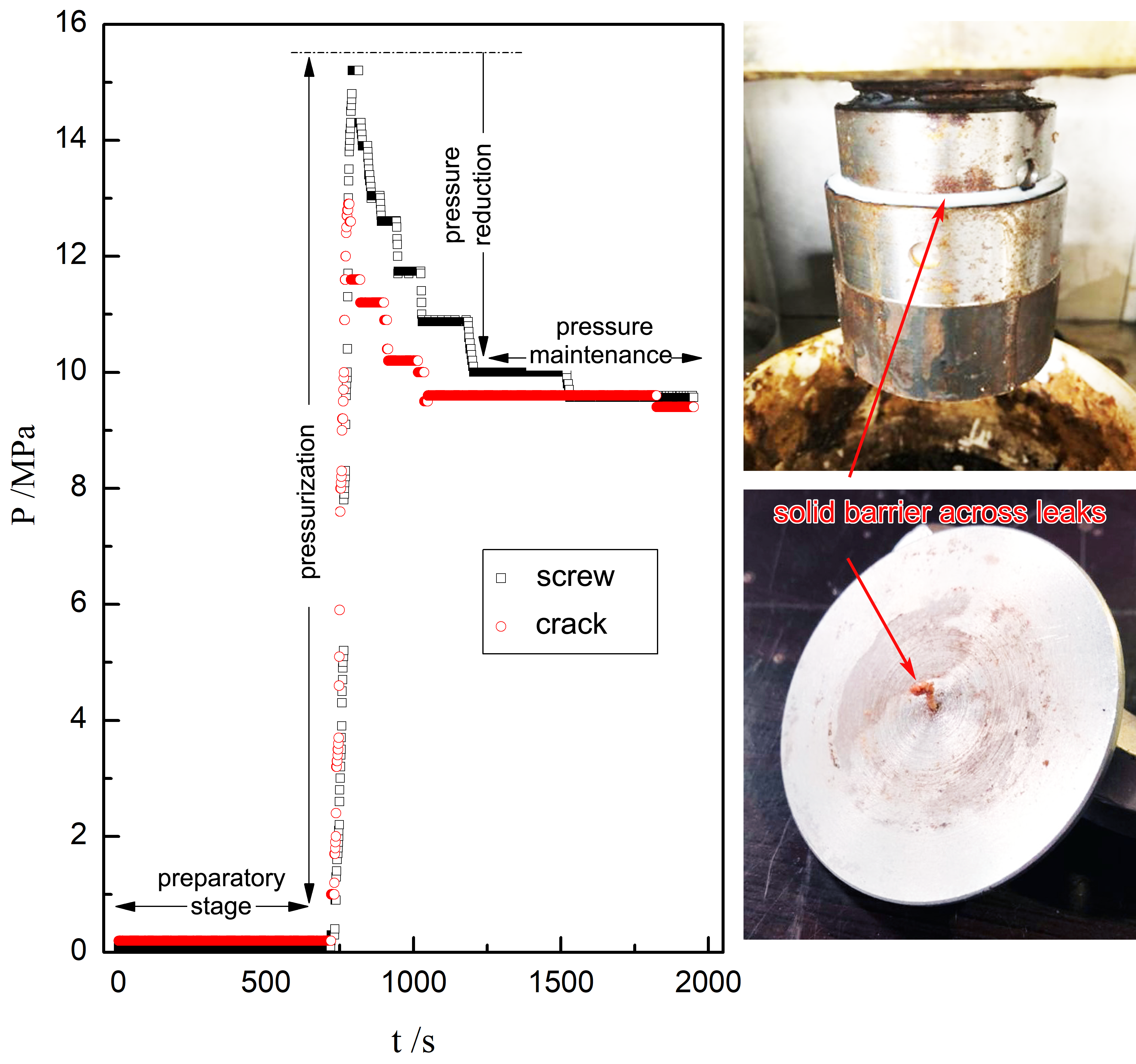
3.2.1. Dynamic Seal of Sealant 0

Figure 5 shows the pressure as a function of the sealing time in two kinds of defects (i.e., screw and crack). For Sealant 0, the sealing process involved four stages: a preparatory stage, a pressurization stage, a pressure reduction stage, and a maintenance stage. The screw and crack offered analogous seal processes. In the preparatory and pressurization stages, the leak temperature and pressure can be adjusted in terms of the sealing conditions. In the pressure reduction and maintenance stages, the sealing capability of the sealant can be effectively evaluated using the real-time pressure data. For example, the activated pressure was controlled at about 12 MPa, and the pressure maintenance stage occurred 500 s after the pressurization. This result reveals that Sealant 0 is capable of successfully curing the investigated defects.
Figure 5 also shows the corresponding solid barriers formed in the two defects. As anticipated, flexible solids can be formed outside of the leak sites, and this sealing process is quite consistent with the results of Rusch et al. [6]. Given the integrity of the solid barrier, the repaired seals possess an excellent capability to resist forward- and inverse-pressure.

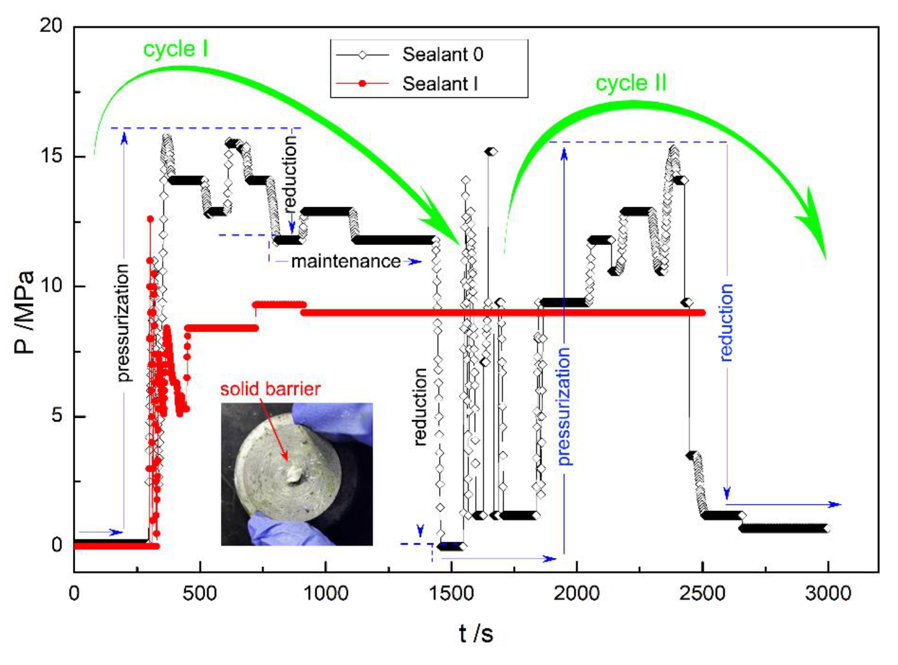
3.2.2. Comparison of the Seal Pressures of Sealants 0 and I

In order to explore the sealing property enhanced by the introduced promoters, the dynamic sealing processes of Sealant 0 and Sealant I were compared, and the results are illustrated in Figure 6. Herein, the larger defect (0.5 mm × 1.0 mm × 10 mm) was employed.
In Figure 6, the real-time pressure variation of Sealant I is completely different from that of Sealant 0 for the larger modeling crack. Because of the introduction of fiber, Sealant I has a much stronger sealing property than Sealant 0. Sealant I experienced an entire sealing process, which included pressure reduction and maintenance stages. During the experiment, an effective seal was formed across the crack after 500 s (inset image in Figure 6). In contrast to Sealant I, the real-time pressure curve of Sealant 0 has a larger oscillation, and in particular, the pressure curve experienced two sealing processes, i.e., cycle I and cycle II, which occurred at 300–1500 s and 1900–2500 s, respectively. According to the trend of the pressure change, it can be concluded that first, a weak seal was formed across the larger crack, and then, it was destroyed. As the sealing process proceeded, a new seal may be formed, but it is broken in a short time. This pressure variation suggests that Sealant 0 failed to plug the larger crack. Therefore, the introduced fiber material plays a dominant role in improving the seal’s structure and enhancing the sealing property.

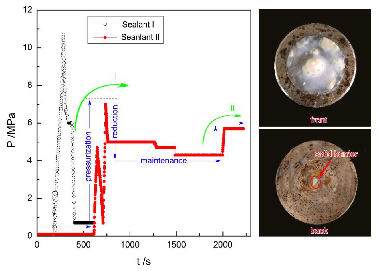
3.2.3. Comparison of the Seal Pressures of Sealants I and II

To investigate the cooperativity of the solid sealing materials, i.e., fiber and rigid particles, in enhancing the leak repairs, a comparison of the dynamic sealing behaviors of Sealants I and II was conducted using the larger crack (0.6 mm × 2.0 mm × 10 mm).
Figure 7 shows the pressure change over time during the sealing process. For Sealant I, there are notable pressurization and reduction stages, but there is no corresponding maintenance stage. Undoubtedly, the lack of a maintenance stage indicates that a seal failed to form in the larger crack. However, in comparison with Sealant I, Sealant II underwent the entire sealing process, and in particularly, the maintenance stage occurred after 750 s. This could simply mean that an effective seal occurred and, moreover, another pressurization (up to about 6 MPa) test was implemented to evaluate the pressure-bearing capability of the seal formed in the larger crack. Apparently, the solid barrier was quite pressure-resistant, meeting the requirement of SCP repair. Furthermore, the inset images show the solid barriers formed in the front and back of the modeled defect. By comparing the solid barriers shown in Figure 5 and Figure 6, it can be seen that the solid barrier only grew in the crack. This is probably due to an introduction of properly sized rigid particulates into the sealant, which could significantly vary the leak geometry and migration path [19]. The addition of rigid particles can cause the surface area to leak area ratio to increase by means of a bridging block in the leak path. As Rusch et al. [20] have reported, for a pressure-activated sealant, the higher the surface area to leak area ratio, the more likely it is that the leak is sealed.

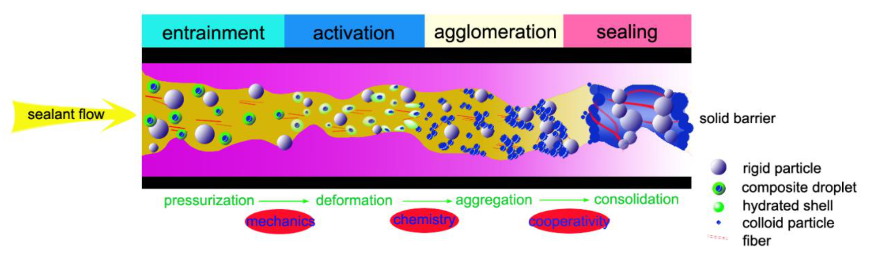
3.3. Mechanism on Self-Adaptive Seal of Composite Sealants

Seal formation is a multi-stage, system-dependent process, which is influenced by many factors, such as multiple components, leak geometry, particulate morphology, and flow velocity. To better understand seal-enhancing behavior, we established a mechanochemical coupling model that describes the seal growth process in the multiphase transportation path, combined with the cooperative jamming effect of the solid sealing materials (Figure 8).
In the mechanochemical coupling model, mechanical deformation caused by the defect flow field can firstly activate the composite droplets, and then these activated droplets will further have a chemical agglomeration to plug the defect. As can be seen in Figure 8, the seal formation process mainly involves four stages, i.e., entrainment, activation, agglomeration, and sealing, which are closely related to the liquid–solid jamming transition of the sealant fluid. First, the multiple components (such as the sealant, rigid particles, fiber, and stabilizer) were entirely dispersed under shear function. Second, when the sealant system reached the leak sites, the composite droplets constructed by the colloid core and the hydrate shell seriously deformed under the differential pressure, and then, the hydrate shell broke down [21,22,23], leading to the activation of the colloid particles. Unsurprisingly, the morphology of the composite droplets varies substantially in this stage. Third, the active colloidal particles quickly reacted, adhering to each other, and strong aggregation occurred as the reaction proceeded, which is indicative of colloidal cohesion [24,25]. Finally, the formed aggregation segments were embedded with fiber to strengthen the structure of the solid seal. Moreover, the introduced rigid particles plugged the crack through the bridging effect to cooperatively facilitate the seal repair. It is noteworthy that the sealant reaction mainly originated from the mechanical deformation, while the liquid-solid jamming transition of the sealant in the leak sites is a mechanochemical coupling reaction. As a matter of fact, in nature, this type of self-adapting seal is similar to the fuzzy-ball block [26] and the auto-adapting lost circulation control [27], which can fill up the leak geometry in-situ and neglect physics morphology of leaks.

3.4. Field Implementation
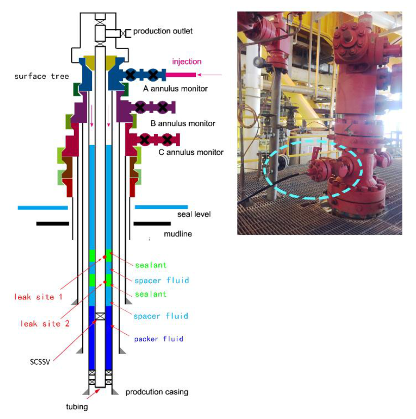
After a successful laboratory test, a real implementation in a well was required to confirm the application and robustness of the new composite pressure-activated sealant. In general, the field trial mainly contains leak status evaluation, repair design, and seal examination.

3.4.1. Leak Status

A candidate onshore well in the South China Sea was chosen to deploy the technology. The candidate well for the composite pressure-activated sealant technology was selected based on several criteria: accessibility, economic advantage, leak severity, and leak cause. The database constructed during the collection of the field data was used for the selection, and the corresponding leak parameters are provided in Table 1.
The selected well had experienced an SCP problem in the A annuli for two years, and the SCP value was 0.7 MPa. When bled to zero, the SCP would increase to 0.7 MPa in 45 min. Diagnostics indicated that two leak paths had developed in the 73.0 mm tubing, at 164.02 m and 185.36 m. The packer fluid level was 208.5 m in the A annuli. That is, the leak sites were 20–50 m higher than the fluid level. These data were important for the subsequent injection design.

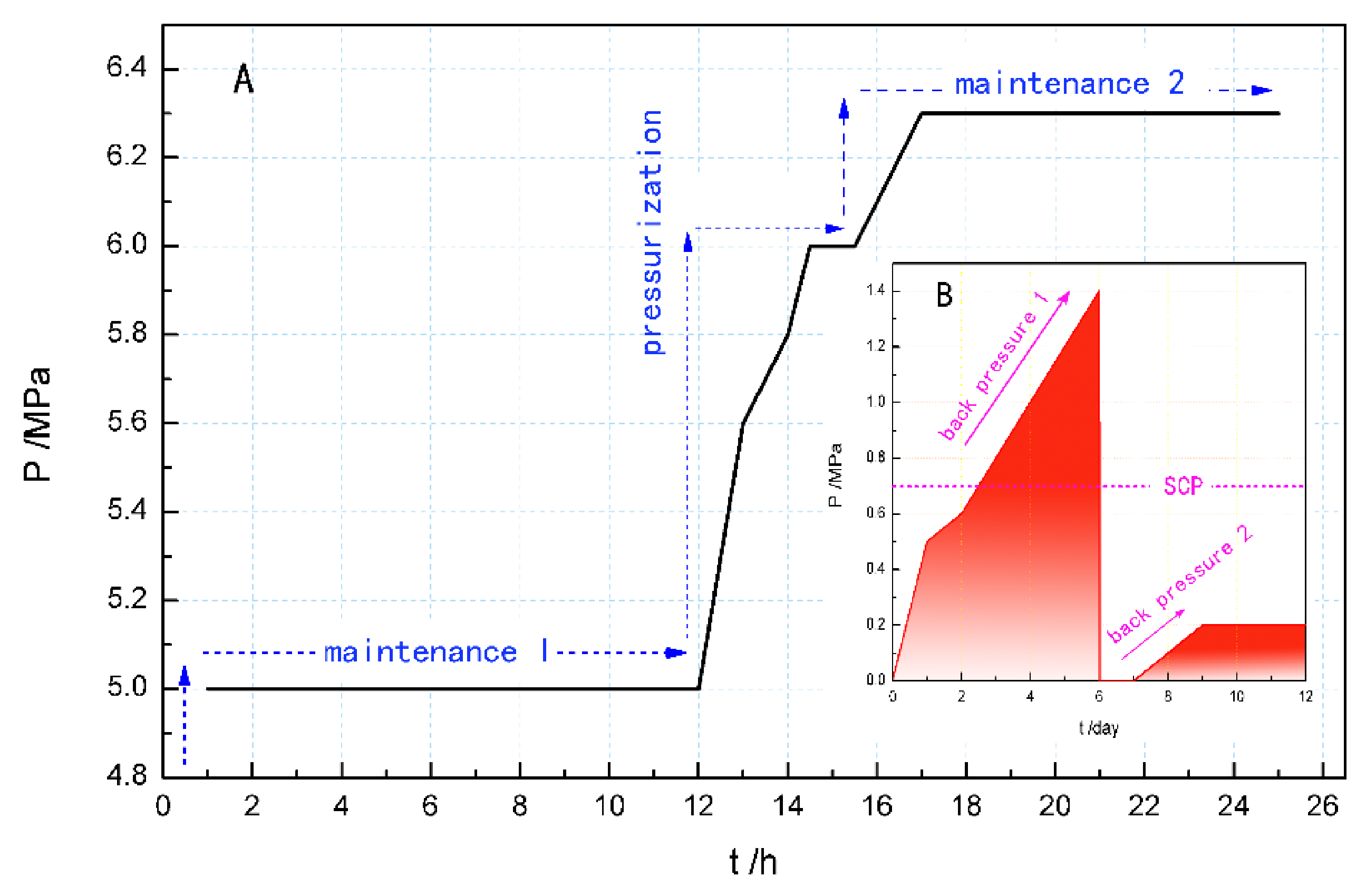
3.4.2. Leak Repair Execution

The platform delivery method was used, and a batch treatment was carried out in the leak curing operation. First, a skid holding the sealant and spacer fluid injectors was connected to the A annuli through the skid line (Figure 9). Subsequently, a bleed-off operation was implemented to lower the SCP as far as possible, and then, a certain volume of spacer fluid and sealant was injected into the A annuli in turn. It is worth noting that the spacer fluid was injected twice. The first injection was to flush the A annulus, while the second injection was performed to drive the sealant and transmit the wellhead pressure to the leak sites. Second, a stepwise pressurizing procedure was employed to create the differential pressure, and the interval time was one hour. Using the skid pump, the squeeze pressure was increased to the designed value to create a moderate differential pressure at the leak site. According to the laboratory results, the differential pressure was controlled within the range of 3–8 MPa. An additional 6 h was allowed for the seal to establish. Finally, the sealing property was evaluated through both build-up pressure and back-pressure operations. The residual sealant and spacer fluid remained in the annulus area as annulus protection fluids.

3.4.3. Seal Evaluation

The trends of the build-up and back-pressure variations are shown in Figure 10. It is clear that the seal was effectively repaired by the composite pressure-activated sealant.
In the build-up pressure process, a constant pressure stage was observed at 5.0 MPa for 12 h, indicating that a seal was established. For the purpose of the evaluation of the seal’s pressure bearing capability, the annular pressure was further increased to 6.4 MPa through the squeezing operation, and the pressure remained steady for 7 h, indicating a successful forward blockage. However, in the back-pressure process, the back-pressure value was recorded twice to check the seal validity. In the first back-pressure variation, the back-pressure value reached 1.4 MPa, which was significantly higher than the SCP. This is probably due to a gas slippage effect. That is, the gas was initially squeezed into the A annuli with the spacer fluid, and then, it was released as bubbles, which aggregated above the liquid level, leading to a larger annular pressure. It should be pointed out that as might be expected, the back-pressure ratio was much lower than that tested before the sealing treatment. In the second back-pressure process, the pressure only increased to 0.2 MPa in 3 days, which is lower than the initial SCP. Herein, to some degree, the residual pressure can be ascribed to the influence of the elevated downhole temperature. Otherwise, the back-pressure should be comparable to the SCP. Therefore, it can be reasonably concluded that the minor defects were effectively repaired in terms of pressure variation.

4. Conclusions

In this paper, both laboratory tests and field tests were conducted to verify the enhanced sealing capability and to validate the applicability of a newly developed composite pressure-activated sealant. A unique composite pressure-activated sealant containing extra promoters, i.e., rigid particles and flexible fiber, was successfully developed in the laboratory and tested in the field. The dispersed particles that play key role in leak repair were regular and had a narrow size distribution of 300–400 μm. Compared with a traditional pressure-activated sealant, the composite sealant has a much stronger sealing property, because of the cooperative effect of the liquid-solid sealing materials in the leak sites. The sealing applicability can be extended to the larger defect (0.6 mm × 2.0 mm × 10 mm) under 15 MPa. In view of the dynamic seal process, a mechanochemical coupling model was preliminarily established to rationalize the pressure response feature of the self-adapting repair for the pressure-activated sealant. Field implementation verified and validated the applicability of the composite pressure-activated sealant in treating leaks of 73.0 mm tubing. These conclusions will not only throw some light on self-adaptive sealing behavior of pressure-activated sealant, but also provide a cost-effective alternative for the maintenance of wellbore integrity.
As a result of the unique features of the composite pressure-activated sealant, the present mechanochemical coupling model, which primarily relies upon the flow field distribution and the deformation of the hydrated particulates, appears to be somewhat limited in its ability to quantitatively describe self-adapting seals. In future studies, intense efforts will be devoted to explicitly accounting for the relationships between the leak geometry, fluid dynamics, microscopic aggregation, and sealing performance.

Author Contributions

Conceptualization, M.X.; data curation, X.H. (Xin Huang) and X.X.; investigation, L.X. and J.X.; methodology, X.H. (Xiaohe Huang), C.M., and M.H. All authors have read and agreed to the published version of the manuscript.

Funding

This work was financially supported by the Welfare Technology Research Project of Zhejiang Province (No. LGG20E040002) and Zhoushan Science and Technology Plan Project (No. 2020C21006).

Conflicts of Interest

The authors declare no conflict of interest.

References

  1. Kupresan, D.; Heathman, J.; Radonjic, M. Casing expansion as a promising slution for microannular gas migration. SPE Drill. Completion 2014, 29, 336–371. [Google Scholar] [CrossRef]
  2. Bryson, K.; Fowkers, M.; Booth, P.; Mock, C. Pipeline repair using epoxy technology; Paper OTC-25656-MS. In Proceedings of the Offshore Technology Conference, Houston, TX, USA, 4–7 May 2015. [Google Scholar] [CrossRef]
  3. Mebratu, A.; Nerland, B.; Kleppan, T. Annular barrier re-establishment using a long-life, high-strength polymer gel system; Paper SPE 86547. In Proceedings of the SPE International Symposium and Exhibition on Formation Damage Control, Lafayette, LA, USA, 18–20 February 2004. [Google Scholar] [CrossRef]
  4. Al-Ansari, A.A.; Al-Refal, I.M.; Al-Beshri, M.H.; Pino, R.M.; Leon, G.A.; Knudsen, K.; Sanabria, A.E. Thermal activated resin to avoid pressure build-up in casing-casing annulus (CCA); Paper SPE-175425-MS. In Proceedings of the SPE Offshore Europe Conference and Exhibition, Aberdeen, UK, 8–11 September 2015. [Google Scholar] [CrossRef]
  5. Lakatos, I.; Szentes, G.; Toro, M.; Karaffa, Z.; Vago, A. Mitigation of formation damage caused by chemical overdosing in water shut-off treatments; Paper SPE-199292-MS. In Proceedings of the SPE International Conference and Exhibition on Formation Damage Control, Lafayette, LA, USA, 19–21 February 2020. [Google Scholar] [CrossRef]
  6. Rusch, D.W.; Ellis, B.C. Use of pressure-activated sealants to cure sources of casing pressure; Paper SPE-55996-MS. In Proceedings of the SPE Western Regional Meeting, Anchorage, AK, USA, 26–27 May 1999. [Google Scholar] [CrossRef]
  7. Cary, D.N.; Groomer, V. Drilling riser alternative repair methods for leaking joint seals utilizing pressure-activated sealant technology; Paper SPE-101216-MS. In Proceedings of the IADC/SPE Asia Pacific Drilling Technology Conference and Exhibition, Bangkok, Thailand, 13–15 November 2006. [Google Scholar] [CrossRef]
  8. Johns, J.E.; Cary, D.N.; Dethlefs, J.C.; Ellis, B.C.; McConnell, M.L.; Schwartz, G.L. Locating and repairing casing leaks with tubing in pace-ultrasonic logging and pressure-activated sealant methods; Paper SPE-108195-MS. In Proceedings of the SPE Offshore Europe Oil and Gas Conference and Exhibition, Aberdeen, UK, 4–7 September 2007. [Google Scholar] [CrossRef]
  9. Bybee, K. Microannulus leaks repaired with pressure-activated sealant. J. Pet. Technol. 2005, 57, 58–60. [Google Scholar] [CrossRef]
  10. Singh, A.K.; Patil, B.; Kishore, K.; Khanna, M.; Varma, S.R.; Anderson, C. Casing leak investigation & successful repair by application of pressure-activated liquid sealant in a newly completed well in offshore environment-a case study; Paper SPE-173826-MS. In Proceedings of the SPE Bergen One Day Seminar, Bergen, Norway, 22 April 2015. [Google Scholar] [CrossRef]
  11. Cary, D.N.; Julian, J.Y.; Jackson, J.C.; Ellis, B.C. Pressure-activated sealants-non-rig solutions in mature fields in Alaska; Paper SPE-163944-MS. In Proceedings of the SPE/ICoTA Coiled Tubing & Well Intervention Conference & Exhibition, The Woodlands, TX, USA, 26–27 March 2013. [Google Scholar] [CrossRef]
  12. Rodrigues, V.F.; Figueiredo, G.G.; Rusch, D.W.; Videira, J. Use of pressure-activated sealant to cure leaks in subsea wells-a case study in Campos Basin, Brazil; Paper SPE-96432-MS. In Proceedings of the SPE Annual Technical Conference and Exhibition, Dallas, TX, USA, 9–12 October 2005. [Google Scholar] [CrossRef]
  13. Rusch, D.W.; Romano, M. Internal repair of pipeline leaks using pressure-activated sealant; Paper SPE 91400. In Proceedings of the SPE Eastern Regional Meeting, Charleston, WV, USA, 15–17 September 2004. [Google Scholar] [CrossRef]
  14. Guo, L.M.; Xiao, M.; Liu, J.X. Pressure-activated sealant. Drill. Fluid Completion Fluid 2015, 32, 65–68. [Google Scholar]
  15. Xing, X.S.; Xu, L.; Feng, H.Z.; Liu, S.J.; Xu, M.B.; Chen, K. A differential pressure-activated sealant: Preparation, sealing performance and working mechanism. Drill. Fluid Completion Fluid 2019, 36, 789–794. [Google Scholar]
  16. Wang, L.G.; Yan, J.N.; Feng, W.Q. Design and lab evaluation of ideal packing bridging drilling and completion fluids. J. China Univ. Pet. 2007, 31, 72–76. [Google Scholar]
  17. Huang, X.B.; Sun, J.S.; Lv, K.H.; Liu, J.P.; Shen, H.K.; Zhang, F. Application of core-shell structural acrylic resin/nano-SiO2 composite in water based drilling fluid to plug shale pores. J. Nat. Gas Sci. Eng. 2018, 55, 418–425. [Google Scholar] [CrossRef]
  18. Minko, S. Responsive polymer brushes. J. Macromol. Sci. Part C 2006, 46, 397–420. [Google Scholar] [CrossRef]
  19. Razavi, O.; Vajargah, A.K.; Oort, E.; Aldin, M.; Govindaragan, S. Optimum particle size distribution design for lost circulation control and wellbore strengthening. J. Nat. Gas Sci. Eng. 2016, 35, 836–850. [Google Scholar] [CrossRef]
  20. Rusch, D.W. Subsea Leaks Cured with pressure-activated sealant; Paper SPE-88566-MS. In Proceedings of the SPE Asia Pacific Oil and Gas Conference and Exhibition, Perth, WA, Australia, 18–20 October 2004. [Google Scholar] [CrossRef]
  21. Liao, B.; Zhang, G.F.; Wang, L.H.; Zhu, Y.; Yang, J. Deformation and breakup behaviors of a drop in amient liquid under impact. J. Exp. Fluid Mech. 2016, 30, 9–16. [Google Scholar]
  22. Bai, B.F.; Luo, Z.Y. Deformation, motion and adhesion of complex droplets under flow. Chin. Sci. Bull. 2015, 60, 3349–3366. [Google Scholar] [CrossRef]
  23. Lipowsky, R. Coupling of bending and stretching deformations in vesicle membranes. Adv. Colloid Interf. Sci. 2014, 208, 14–24. [Google Scholar] [CrossRef] [PubMed] [Green Version]
  24. Fu, Z. Rubber Material and Techniques, 1st ed.; Chemical Industrial Press: Beijing, China, 2013; pp. 109–119. [Google Scholar]
  25. O’Reilly, R.K.; Hawker, C.J.; Wooley, K.L. Cross-linked block copolymer micelles: Functional nanostructures of great potential and versatility. Chem. Soc. Rev. 2006, 35, 1068–1083. [Google Scholar] [CrossRef] [PubMed]
  26. Zheng, L.H.; Kong, L.C.; Cao, Y.; Wang, H.Y.; Han, Z.X.; He, X.Q. The mechanism for fuzy-ball working fluids for controlling & killing lost circulation. Chin. Sci. Bull. 2010, 55, 1520–1528. [Google Scholar]
  27. Lv, K.H.; Qiu, Z.S.; Wei, H.M.; Li, X.F.; Song, Y.S. Study on techniques of auto-adapting lost circulation resistance and control for drilling fluid. Acta Pet. Sin. 2008, 29, 757–760. [Google Scholar]
Figure 1. The process for the deterministic assembly of a three-dimensional (3D) mesostructure of central particulates in the preparation of a composite pressure-activated sealant. (A) Hydrophobic and hydrophilic segments of the XNBRL, (B) self-assembly of amphiphilic triblock copolymers into a 3D spherical micelle, (C) hydration shell formed by the adsorbed water, (D) shrinkage or breakage of the hydration shell caused by the brine, (E) flocculation of the active colloid particulates, and (F) coalescence of the intermediates into a complex 3D droplet.
Energies 13 05597 g001
Figure 2. The designed high temperature, high-pressure (HTHP) dynamic sealing detector. (A) Photograph of the designed sealing instrument, (B) schematic of the sealing instrument, and (C) two kinds of modeled defects: cracks (left) and screw damage (right).
Energies 13 05597 g002
Figure 3. Size distribution (left) and mesostructure ((right), ×300) of the coalescence particulates of the composite pressure-activated sealant. The 3D morphology of the grown coalescence particulates is marked. The red line corresponds to cumulative distribution of particulates in the sealant, and the purple circles mark the profile of agglomeration particulates.
Energies 13 05597 g003
Figure 4. Morphology of a particulate cluster and the dispersed solid of the composite pressure-activated sealant. (A) Hydrated particulate clusters with the hydrated layer are marked in purple. (B) Consolidation of the coalescence particulates formed by the dehydration. (C) A single particle that is overlain with fiber. (D) Cross section image of the consolidation product.
Energies 13 05597 g004
Figure 5. Dynamic sealing curves (left) and solid barrier images (right) of Sealant 0 in the different leaks. The right images show solid barriers formed through screw (top) and crack (bottom) defects. The relevant size of the crack is of 0.5 mm × 0.5 mm × 10 mm.
Energies 13 05597 g005
Figure 6. Comparison of the dynamic sealing processes of Sealant 0 and Sealant I in a 0.5 mm × 1.0 mm × 10 mm crack defect. The inset is an image of the solid barrier through the leak site.
Energies 13 05597 g006
Figure 7. Comparison of dynamic sealing curves of Sealant I and Sealant II (left) and solid barrier formed by Sealant II in a 0.6 mm × 2.0 mm × 10 mm crack defect (right). The right provides the solid seals formed in the crack’s front (top) and back (bottom).
Energies 13 05597 g007
Figure 8. Mechanism of enhancing the in-situ sealing of a composite pressure-activated sealant in a leak defect.
Energies 13 05597 g008
Figure 9. Leak repair implemented using platform delivery. (Left): schematic illustration of the slug distribution of the sealant and spacer fluid along the A annuli; (right): photograph of the injection contact with the A annulus monitor.
Energies 13 05597 g009
Figure 10. Pressure variation in the A annuli treated with the composite pressure-activated sealant. (A) Pressure build-up process, and (B) back-pressure process.
Energies 13 05597 g010
Table 1. Leak parameters of the selected well in the South China Sea.
Seal LeaksSCP (MPa)Annular Fluid Level * (m) Leak Position (m) Leak Geometry
Tubing0.7208.5Leak site 1: 164.02Narrow **
Leak site 2: 185.36
* The fluid level and leak position are defined from the tubing spool. ** The equivalent pore diameters of defects are less than 2 mm. Note: SCP = sustained casing pressure.
Publisher’s Note: MDPI stays neutral with regard to jurisdictional claims in published maps and institutional affiliations.

