Abstract
Hydrogen can be produced in undesired ways such as a high temperature metal oxidation during an accident. In this case, the hydrogen must be carefully managed. A hydrogen mitigation system (HMS) should be installed to protect a containment of a nuclear power plant (NPP) from hazards of hydrogen produced by an oxidation of the fuel cladding during a severe accident in an NPP. Among hydrogen removal devices, passive auto-catalytic recombiners (PARs) are currently applied to many NPPs because of passive characteristics, such as not requiring a power supply nor an operators’ manipulations. However, they offer several disadvantages, resulting in issues related to hydrogen control by PARs. One of the issues is a hydrogen stratification in which hydrogen is not well-mixed in a compartment due to the high temperature exhaust gas of PARs and accumulation in the lower part. Therefore, experimental simulation on hydrogen stratification phenomenon by PARs is required. When the hydrogen stratification by PARs is observed in the experiment, the verification and improvement of a PAR analysis model using the experimental results can be performed, and the hydrogen removal characteristics by PARs installed in an NPP can be evaluated using the improved PAR model.
1. Introduction
During a severe accident involving a damage to a reactor core in a nuclear power plant (NPP), hydrogen is produced by oxidation of the nuclear fuel cladding, and the hydrogen is released into the reactor containment building along with water vapor. NPPs must have a hydrogen mitigation system (HMS) installed to protect containment buildings from thermo-mechanical loads caused by hydrogen explosions [1,2,3].
In a broad sense, hydrogen control facilities include devices that affect the distribution and concentration of hydrogen in a containment building, including hydrogen igniters, passive auto-catalytic recombiners (PARs), thermal-recombiners, water spray devices, fan-coolers, filtered containment venting systems (FCVS), mixing blades, rupture foils, and dampers [4].
Currently, PARs [5] and hydrogen igniters are mainly used for hydrogen control of containment buildings in the event of a severe accident [6]. Table 1 compares the two hydrogen control devices [7]. A PAR and a hydrogen igniter are installed in containment buildings for the purpose of preventing hydrogen explosion in advance and have different characteristics as shown in Table 1. PAR operates (hydrogen depletion) when hydrogen comes into contact with the catalyst plates without operator intervention, while the hydrogen removal rate is very low.

Table 1.
Comparison of a passive auto-catalytic recombiner (PAR) and an igniter.
When only PARs are installed in a containment building, the distribution and removal characteristics of hydrogen in a severe accident differ depending on the thermal and hydraulic characteristics in the reactor and containment building and the progression of the severe accident. On the other hand, the hydrogen igniter can quickly remove hydrogen, but it requires an intervention such as an operator’s judgment and operation of an external power source. In the event of a power loss accident, such as a station blackout, it is impossible to operate the igniters without an external power supply, thus, there is a trend to install a battery or an uninterruptible power supply (UPS) as an auxiliary power source (AP1000) [8].
Currently, PARs are being manufactured in various countries and provided to nuclear power plants. Representatively, AREVA [9,10], NIS [10,11], and AECL [10,12,13] are manufacturing and supplying PARs, and recently, KNT [14] and CERACOMB [15] are producing PARs. Platinum or palladium is mainly used as a catalyst component for the recombination of hydrogen and oxygen, and the shape of the catalyst body includes parallel-plates, honeycomb, or pebble types. For maintenance of the catalyst body, it is generally in the form of a detachable cartridge and includes a vertical chamber to improve the inflow rate of the hydrogen gas mixture flowing into the catalyst body and to protect the catalyst body from external conditions. As shown in Table 1, the PAR has a hydrogen removal rate of less than 1 g/s due to the characteristics of the passive device and the limited area of the catalyst body. Therefore, total hydrogen removal performance in a containment can be improved by installing multiple PARs.
The passive characteristic of the PAR is a very effective advantage compared to the active characteristic of the hydrogen igniter, but it has several disadvantages stemming from the characteristics of the passive device design, and these become issues related to the hydrogen control of containment buildings [16,17]. The representative issues related to the hydrogen control by PARs are the startup time delay of PAR, hydrogen auto-ignition by PAR and hydrogen stratification caused by PAR. The first two issues were studied experimentally and numerically by many research groups [18,19,20,21]. On the contrary as far as the authors know, the third issue was not studied experimentally after mentioned in SARNET (severe accident research network of excellence) WP12-2 PARIS-1 [22]. The phenomenon of hydrogen stratification caused by PAR is a kind of a hydrogen stratification induced by PARs installed in a compartment or a containment.
PAR emits high-temperature exhaust gas including water vapor generated by the exothermic reaction of hydrogen and oxygen in the catalyst body. A fresh gas is sucked at the inlet located at the bottom of the PAR chamber by the exhaust gas exiting the outlet located at upper part of the PAR chamber. This natural convection causes the PAR to operate continuously. The density of the mixed gas distributed in the containment building or compartment may vary depending on the temperature and composition. That is, as the temperature of the gas mixture increases, the density decreases, and as the concentration of hydrogen or water vapor in the gas mixture increases, the density of the gas mixture decreases. The high-temperature exhaust gas emitted from the PAR can be accumulated in the upper part of the compartment in which the PAR is installed because the exhaust gas density is relatively low compared to the containment atmosphere. When it happens, it may prevent the formation of a large natural convection caused by the PAR in the compartment. In this case, a hydrogen gas released at the lower compartment area may lose a buoyancy force and mobility by the high-temperature exhaust gas occupying the upper part of the containment. This phenomenon is called PAR-induced hydrogen stratification. Hydrogen stratification by PAR was selected as a topic of interest in terms of hydrogen control in SARNET WP12-2 PARIS-1 [22].
Figure 1 is a simulation of hydrogen stratification caused by PAR through a computational fluid dynamics (CFD) analysis by Reinecke et al. [17,22], and the phenomenon that hydrogen remains in the lower part of the compartment as hydrogen is removed by PAR in the early stage is simulated by the analytical method. Therefore, the necessity of an experiment for physical understanding of hydrogen stratification caused by PAR and verification of the analysis code used to evaluate the hydrogen behavior in a containment building in which PARs are installed has emerged [23].
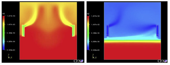
Figure 1.
Hydrogen stratified by the PAR’s activation, (numerical simulation by Reinecke at al.).
Recently, an evaluation of the hydrogen mitigation by PARs installed in a containment of a small integrated modular reactor has been conducted [24]. In the event of a severe accident involving core damage, hydrogen and water vapor generated in the reactor are discharged to an in-containment refueling water storage tank (IRWST). At this time, water vapor is mostly condensed by the cooling water of IRWST, and only hydrogen is discharged to the upper area of the containment where 22 PARs are installed on vertical walls below the ceiling.
Figure 2 shows the schematic of the containment structure and the behavior of hydrogen released through IRWST vent under a severe accident condition. As shown in Figure 2a, after the start of hydrogen release (5500 s after the start of the accident), hydrogen rises to the top of the containment building and follows a typical hydrogen release phenomenon such as mixing with an atmosphere. However, if you look at Figure 2b, the phenomenon that the hydrogen released through the IRWST vents cannot rise to the top and stagnates near the center of the containment building is found. In other words, the initially released hydrogen is diffused as it rises to the top of the containment in the form of a buoyant jet, but as the surrounding hydrogen is removed by the PARs, the temperature of the gas in the upper region of the containment building mixed with the exhaust gas of the PARs increases and the density decreases continuously. It appears that the exhaust gas mixture in the upper region prevents the newly released hydrogen from rising to the top of the containment building. This phenomenon may belong to the phenomenon of hydrogen stratification by PAR proposed in PARIS-1. Therefore, it is expected that hydrogen stratification due to PAR can occur even within the containment building where PAR is installed. So, the phenomenon of hydrogen stratification by the PARs installed in the containment of the small integrated modular reactor has been found in the analytic study using existing physical models of PARs. Therefore, a demonstrative experiment for hydrogen stratification caused by PAR is required. If the hydrogen stratification phenomenon caused by PAR is reproduced through experiments, the PAR analysis model can be verified and improved using the experimental results, and the hydrogen removal characteristics of PAR in the operating nuclear power plant can be evaluated using the improved PAR model.
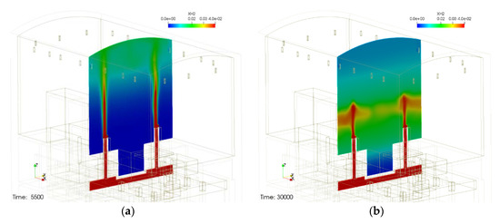
Figure 2.
Hydrogen stratification induced by PARs installed in a small modular reactor containment, (a) before hydrogen stratification and (b) hydrogen stratification occurred.
2. SPARC-PAR Test Facility
For the experimental simulation of hydrogen stratification caused by PAR, a SPARC (Spray–Aerosol-Recombiner-combustion test facility) experimental facility is used. SPARC is a test facility for the simulation of hydrogen behaviors which may occur in a containment building during a severe accident. It consists of a pressure vessel with a volume of 82 m3 and heaters which is capable of controlling the wall temperature. Figure 3 shows the schematic shape of the SPARC pressure vessel, and Table 2 denotes the representative specifications of the SPARC pressure vessel.
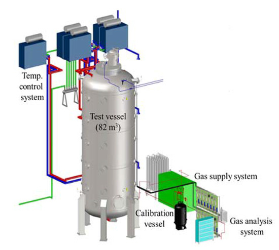
Figure 3.
SAPRC test facility.
Table 2.
Specification of the Spray–Aerosol-Recombiner-combustion test facility (SPARC) test facility.
The SPARC vessel was designed for the purpose of separate effect tests (SET) related to hydrogen behaviors in a containment. The height and aspect ratio of height to diameter of the SPARC vessel was decided by geometry and Rayleigh number similarities to a natural convection flows in a large dry containment. The temperature of the SPARC pressure vessel is basically controlled using three oil jackets installed on the outer wall of the pressure vessel, oil heaters, and oil pumps. There exist many ports on the pressure vessel for experimental measurement and visualization, and for this reason, the outer wall of the pressure vessel cannot be completely covered with the oil jackets, so electric heaters are additionally installed and heated for some outer walls uncovered by oil jackets.
For temperature measurement of the SPARC vessel wall and gas in the vessel, K-type thermocouples of OMEGA (CO3-K, inner diameter 0.25 mm bead, reaction speed 300 ms) are used. The thermocouples installed inside vessel are connected to the data acquisition system outside the vessel through a feed-through (PFTFS-8K, OMEGA, leak rate of 1 × 10⁻⁷ cc air/s at a maximum pressure of 138 bar and diameter of connection wire: 0.812 mm).
Because water vapor is generated from hydrogen–oxygen recombination by the PAR during the SPARC experiment, hydrogen concentration can change depending on the vapor concentration. Probe-type hygrometers (E+E Elektronik, EE33) that can measure directly inside the SPARC vessel are installed since water vapor is condensable. The vapor mole concentration () can be calculated by Equation (1) from the measured relative humidity (RH) and the gas temperature (T).
where is a saturation pressure at the gas temperature T.
For the measurement of hydrogen concentration thermal conductivity sensors (FTC300, Messkonzept, maximum pressure of 20 bar) with a gas sampling system are used. When a high-temperature gas sample enters the sensor unit, heat transfer rates may vary depending on the temperature. Therefore, the sampled gas temperature should be maintained within the range of −5 to 50 °C. Since a cooling channel is installed in front of the hydrogen sensors in the SPARC test facility, the temperature of the hot gas sampled from the experimental vessel decreases during the sampling process. If steam condensation occurs inside the hydrogen sensor, it may affect heat transfer characteristics, so the steam must be completely removed before the hydrogen sensor. In the SPARC test facility, a condensation trap, and a filter are used to remove the vapor contained in the sampled mixed gas. The SPARC gas analyzer is composed of 14 units of hydrogen sensor, 4 units of oxygen sensor, and pumps that control the sampling flow rate (NMP 830 KNDC DC motor: 24 V, flow rate: 3.1 L/m, maximum measuring pressure: 1 bar, KNF). The gas mixture sampled from the experimental vessel passes through a pump and a flow meter, and the hydrogen concentration is measured. Four of the hydrogen sensors are connected with oxygen sensors (PMA 1000, M&C, Germany, principle paramagnetic, reaction time less than 1 s, sampling range: 25 to 60 L/h, temperature range: −10 to 50 °C, maximum pressure: 1.6 bar).
As noted above, the measured hydrogen and oxygen concentrations are at a dry condition, so the concentrations at a wet condition must be calculated by Equation (2) with the measured relative humidity.
The SPARC test apparatus is constructed as a device that can experimentally evaluate various thermal and hydraulic phenomena caused by PAR and characteristics of PAR. In this study, an experimental simulation was conducted to evaluate the possibility of stratification of hydrogen due to PAR installed in a containment during a severe accident. For this study, one of the small-sized PARs, KPAR-40 designed and manufactured by KNT, is used. The basic size of the PAR is 340 × 335 × 1400 mm, and at the bottom, four catalyst bodies (150 × 150 × 50 mm) are placed in a cartridge and mounted in the PAR chamber. The catalyst body used in the PAR experiment is made of a platinum catalyst material and ceramic (2MgO·2Al2O3·5SiO2) as a base material. In order to evaluate the performance of the PAR from the SPARC experiment, a skirt was additionally manufactured and installed under the PAR chamber as shown in Figure 4 to measure hydrogen concentration, oxygen concentration, humidity, temperature, gas inflow rate, etc. at the entrance and exit of the PAR. The gas flow measurement sensor used in the experiment is a Hoentzsch vane-wheel type speedometer (model name ZS25GFE-mn20) inserted into a measurement point, and it measures the gas velocity (volumetric flux) by counting the number of rotations when the pinwheel turns according to the gas flow.
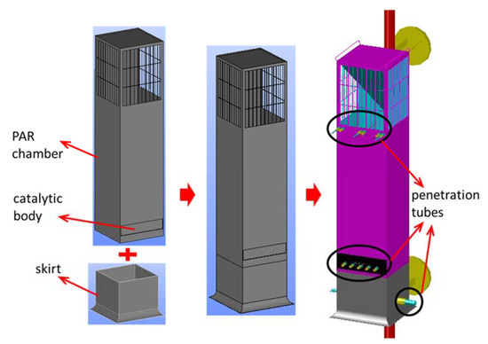
Figure 4.
Construction of a test PAR for the SPARC-PAR experiment.
3. PAR Performance
A hydrogen depletion rate of the KNT′s PAR is expressed in a similar form to AECL′s PAR correlation, but small, medium, and large PAR correlations were unified by multiplying a factor according to the size of the PAR [14].
where:
- -
- : hydrogen concentration [vol.%];
- -
- p: pressure [bar];
- -
- T: temperature [K];
- -
- Values of constant parameters: ;
- -
- N: size factor, 1 for KPAR-40, 2 for KPAR-80, and 4 for KPAR-160
The hydrogen depletion rate of the KNT′s small PAR KPAR-40 calculated by Equation (4) according to the inlet hydrogen concentration at temperature of 333 K and pressure of 1.5 bar is compared with AREVA’s FR380T and AECL PAR in Figure 5. It shows that the performance of hydrogen depletion by the KNT’s KPAR-40 is in the range of 0.1 to 0.7 g/s for the inlet hydrogen concentrations from 2 to 8 vol.% which are the conditions of the SPARC-PAR tests.
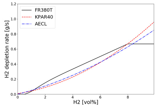
Figure 5.
Hydrogen depletion rates along the inlet concentration for small PARs at T = 333 K and p = 1.5 bar.
Basically, an equation for the hydrogen removal rate of the PAR can be derived from the conservation equations of mass and momentum with an assumption of steady or quasi-steady states. In Equation (5), hydrogen concentrations at the inlet and outlet are required to get the PAR depletion rate.
where are density, velocity, mass fraction, and gas constant, respectively. is the molecular weight of the gas mixture and is the inlet area of the PAR.
The temperature of the PAR catalyst body and the exhaust gas temperature of the PAR rise very high due to an exothermic reaction of hydrogen and oxygen. And because the sensor of the hygrometer for measuring relative humidity is very vulnerable to gas temperature, it is technically difficult to measure the steam concentration at the PAR exit which is used to get real wet concentration of hydrogen from Equation (2). Instead of Equation (5), Equation (6) can be used with an assumption of equal molecular weights of gas mixture at the inlet and outlet [25].
Equation (6) needs only dry hydrogen concentration at the exit, and it gives similar hydrogen depletion rates with about 0–2% discrepancy compared to Equation (5).
4. Test Conditions for SPARC-PAR Experiments
In this study, an experimental simulation was conducted to evaluate the possibility of hydrogen stratification due to PARs installed in a containment building during a severe accident. Two parameters were considered as the main experimental factors of the SPARC-PAR (SP) experiment.
The first is to evaluate the hydrogen distribution and the PAR performance according to the mass flow rate of hydrogen injected, and the second is to evaluate the behavior of hydrogen according to the location or arrangement of the PARs. Three different configurations of the PARs were considered in this study as shown in Figure 6. The first configuration (2 PARs in parallel) is to place two PARs facing each other at the same elevation of 6 m from the bottom of the SPARC vessel to the bottom of the PAR chamber. The second configuration is to use only one PAR and the third configuration (2 PARs staggered) is to place two PARs facing each other at different elevations of 4.5 and 6 m.
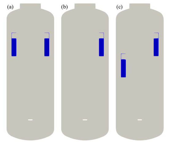
Figure 6.
PAR configurations for the SAPRC-PAR experiment. (a) 2 PARs in parallel; (b) 1 PAR; (c) 2 PARs staggered.
In general, when PARs are installed in a compartment of a containment, they are located on the upper part of the compartment in consideration of stratification on the upper part of the compartment due to the buoyancy of hydrogen. In addition, they are installed at intervals of tens of centimeters from walls in order not to interfere with the natural circulation flow caused by PARs. The arrangement of PARs in the compartment from which hydrogen is released is similar to (a) or (b) in Figure 6, and an experiment on the staggered arrangement of PARs has been added to reflect the characteristics of hydrogen stratified by PAR. As a performance requirement of a PAR installed in a containment, hydrogen removal rate of 0.2 g/s at 4 vol.% hydrogen concentration condition is required for a small PAR. In this experiment, 0.4 g/s, which is the hydrogen removal rate of the two PARs under the condition of 4% hydrogen concentration, was selected as the hydrogen injection condition.
The SPARC-PAR tests were performed in a series from SP1 to SP7, whose test conditions are shown in Table 3. The SP1 and SP2 tests were conducted with different hydrogen mass flow rates on the same configuration. SP3 is a test with one PAR installed in the vessel. The tests from SP4 to SP7 were conducted on the same PAR configuration and similar hydrogen mass flows and durations.
Table 3.
Test conditions for the SPARC-PAR experiment.
Hydrogen and oxygen measurement locations are depicted in Figure 7 for the three PAR configurations. As shown in the figure, sensors are shifted according to the PAR elevation. Hydrogen injection pipe is vertically installed at the bottom of the vessel and the diameter and elevation of the injection nozzle is 0.3 and 2.0 m, respectively.
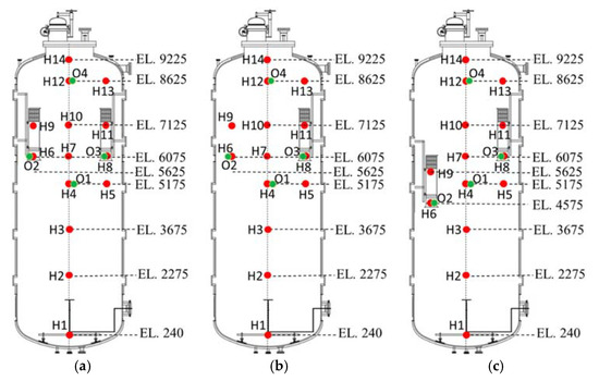
Figure 7.
Measurement points of hydrogen and oxygen concentrations for SAPRC-PAR experiment, O: oxygen sensor and H: hydrogen sensor. (a) 2 PARs in parallel; (b) 1 PAR; (c) 2 PARs staggered.
5. Experimental Results
The SP1, SP3, and SP5 test results are considered in this study to evaluate hydrogen stratification according to the PAR configurations. The main purpose of the SP4, SP5, SP6, and SP7 tests is to evaluate the reproducibility of the results through the repeated tests, but it was difficult to control the hydrogen injection flow rate. In the case of the SP5 test, the mass flow rate of hydrogen injection was well maintained at 0.4 g/s. So, the SP5 test was chosen to comparatively evaluate the hydrogen distributions with the SP1 and SP3 tests.
5.1. SP1 Test
In the SPARC-PAR SP1 experiment, two PARs were installed in parallel to face each other. The mass flow rate of hydrogen discharged to the hydrogen injection nozzle was set to 0.6 g/s. Figure 8 shows the mass flow rate of hydrogen actually injected in the SP1 experiment. It was stably injected for about 610 s except an initial peak, and the total injected hydrogen mass was 370 g.
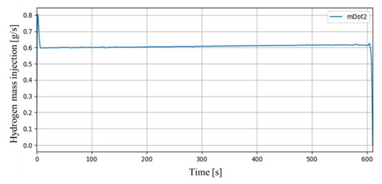
Figure 8.
Mass flow rate of hydrogen injection in SP1 experiment.
Figure 9 shows the change in pressure inside the SPARC vessel. The internal pressure rises up to about 1.13 bar during hydrogen injection, and the pressure gradually decreases after hydrogen injection is complete. The heat generated by the hydrogen recombination of the PARs is the main factor in the rise of internal pressure in SPARC, and after hydrogen injection is finished, the decrease of the number of gas moles due to hydrogen–oxygen recombination becomes more dominant than the pressure increase factor caused by the exothermic operation of the PARs (3 moles of hydrogen–oxygen are converted into 2 moles of water vapor).
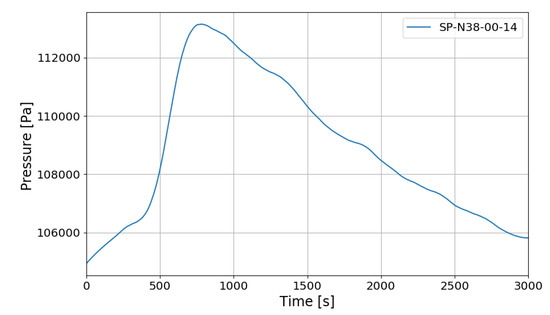
Figure 9.
SPARC internal pressure change in SP1 experiment.
Figure 10 shows the temperature distribution on the vertical center line in the SPARC vessel, where the last two digits of thermocouple names denote the installed elevation. It shows that thermal stratification is occurring above and below the PARs installed in the SPARC vessel.
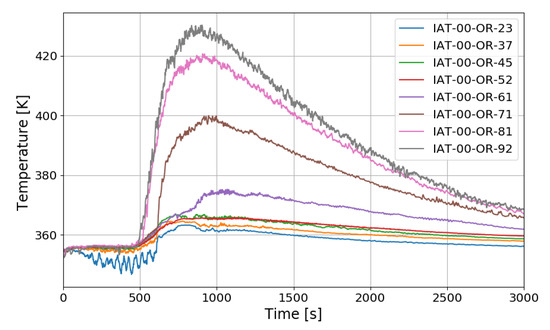
Figure 10.
Temperature distributions along a center line for SP1 test.
Figure 11 shows the change of the hydrogen concentrations in the case of the SP1 test. During the initial 610 s of hydrogen injection, the sensor (H2) just above the hydrogen injection nozzle shows the highest hydrogen concentration, which is generally high in the vicinity of the nozzle outlet because hydrogen is discharged as a jet and diffuses as it rises upward. However, even after the hydrogen injection is stopped, H2 shows higher hydrogen concentration than H12, H14 installed in the dome region of the SPARC vessel, which is very different from a general phenomenon of a hydrogen injection in a compartment.
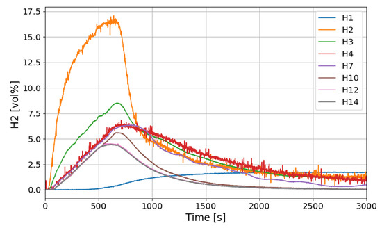
Figure 11.
Hydrogen concentration distributions along a center line for the SP1 test.
Figure 12 shows the change in the oxygen concentration in the case of the SP1 test. The decrease in oxygen concentration indicates the recombination of hydrogen and oxygen by the PARs. Figure 13 and Figure 14 show the characteristics of the PARs in the SP1 test, showing the changes in hydrogen concentrations at the inlets and outlets of the PARs and the temperature changes in the center of the catalyst bodies. It is known that the temperature of the PAR catalyst body increases due to heat generated during recombination of hydrogen–oxygen. In Figure 13, the changes of the hydrogen concentrations at the inlets and outlets of the two PARs are very similar, which depicts the symmetry of the hydrogen behavior in the SPARC vessel in the case of the SP1 test with two PARs installed at the same elevations. The concentrations at the outlets of the PARs decrease rapidly from 450 s, which means that PARs are removing a large portion of the introduced hydrogen. After about 705 s, when the temperature of the PAR catalytic plates reached 700 K (shown in Figure 14), the hydrogens at the outlets of the PARs appear to be fully depleted.
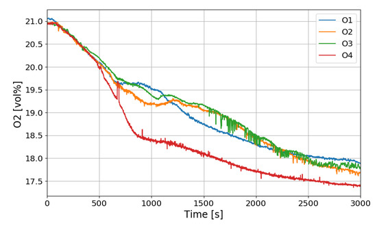
Figure 12.
Oxygen concentration distributions over time for the SP1 test.
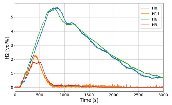
Figure 13.
Hydrogen concentrations at inlets and outlets of the PARs for the SP1 test, H6, H9: inlet and outlet of the left PAR, H8, H11: inlet and outlet of the right PAR.
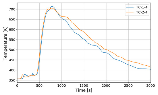
Figure 14.
Temperature changes of the PARs’ catalytic plates in the SP1 test, TC-1-4: right PAR, TC-2-4: left PAR.
In Figure 14, the temperatures on the catalytic plates rise slowly until about 450 s, but they rise steeply from the time when the hydrogen concentrations at the PAR outlets start to quickly reduce. From the figures it is thought that the efficiency of the hydrogen recombination is dependent on the temperature of the catalytic plate, which is one of important parameters of the start-up characteristics of PARs [20,21].
In this experiment, the hydrogen injected at the beginning does not flow into the chamber of the PAR directly, but rises to the top of the vessel, diffuses, descends and distributes around the PAR. Since hydrogen does not exist around the PAR catalyst until about 140 s after hydrogen injection, hydrogen recombination does not occur, and the reaction occurs gradually after about 140 s. The delay time of the initial operation of the PARs is likely to vary depending on the hydrogen concentration around the catalyst bodies, it can be seen that it is affected by the thermal hydraulic phenomenon of the compartment with PARs. In the SP1 experiment, two PARs are installed at the same height, and it seems that the two PARs show almost the same behavior through Figure 13 and Figure 14.
5.2. SP3 Test
The SPARC-PAR SP3 test is a case where one PAR is installed, and hydrogen is injected at 0.4 g/s for about 1000 s. Figure 15 shows the vertical distribution of temperature over time at the center of a SPARC vessel. IAT-00-OR-23 is a thermocouple located directly above the hydrogen injection nozzle.
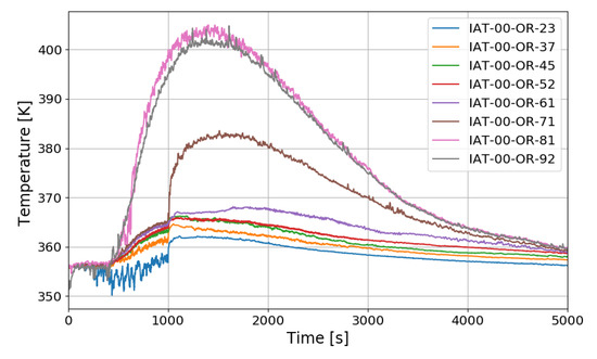
Figure 15.
Temperature distributions along a center line for the SP3 test.
The temperature drop during the hydrogen injection period is due to the low temperature of the injected hydrogen. The overall temperature distribution inside the SPARC vessel has a similar tendency to that of SP1, and a large temperature difference can be confirmed between the top and bottom of the SPARC vessel, and the middle value in the temperature profile along the center line is observed at IAT-00-OR-71 (7.1 m elevation) which is located near the exit of the PARs.
Figure 16 shows the distribution of hydrogen concentration over time along the center line of the SPARC vessel. The trend of hydrogen distribution is similar to that of SP1, but the hydrogen concentration sensor H12 (8.6 m) located above the PAR chamber seems to show the higher concentration than SP1 and this means that the hydrogen reaches the PAR position when one PAR is installed. If intensity of the hydrogen stratification is defined as a maximum difference of the hydrogen concentrations when the concentration at H2 (at the injection nozzle) becomes the same as at H3 (at the point lower than the PAR inlet), the intensity in the SP3 test is about 4 vol.% which is lower than 5 vol.% in the SP1 test.
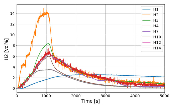
Figure 16.
Hydrogen concentration distributions along a center line for the SP3 test.
Figure 17 shows the hydrogen concentrations at the inlet and outlet of the PAR and Figure 18 shows the temperature change in the catalytic body. H8 in Figure 17 is the hydrogen concentration measured at the inlet of PAR and H11 at the outlet of the PAR. When the PAR initiates the hydrogen depletion, temperature of the catalytic body rises and falls until about 250 s, and then the temperature rises rapidly from about 300 s. This startup characteristic of the PAR is dependent on the design of the catalytic body and flow characteristic of the hydrogen gas mixture. When hydrogen is injected in the SPARC-PAR experiments, the jet does not directly penetrate the PAR chamber, and hydrogen flows into the PAR by diffusion of hydrogen. In Figure 17, it is seen that the hydrogen is continuously being sucked into the PAR chamber even after the hydrogen injection is stopped. From Figure 18, it is thought that higher temperature of the catalytic body than surrounding gas mixture may induce a natural convective flow.
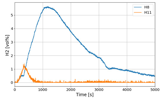
Figure 17.
Hydrogen concentrations at inlet and outlet of the PAR for the SP3 test, H8: inlet, H11: outlet.
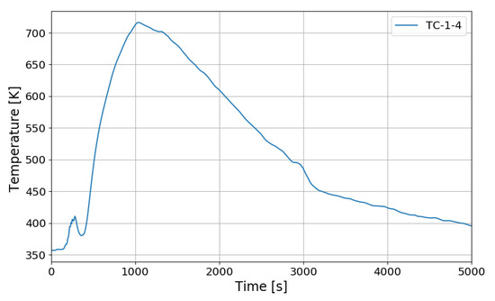
Figure 18.
Temperature behaviors on catalytic plate of the PAR for the SP3 test.
5.3. SP5 Test
The SPARC-PAR tests from SP4 to SP7 are hydrogen stratification experiments by PARs when two PARs are arranged in a staggered manner. PAR1 was installed at the same point (height 6–7.665 m) as the SP1 test, and PAR2 was installed at a lower place (height 4.5–6.165 m). The SPARC-PAR SP5, SP6, and SP7 experiments are similar to the SP4 experiments under the same PAR configuration. The differences among the tests are hydrogen injection rate and period.
In the case of the SP5 test, the mass flow rate of hydrogen injection is maintained at 0.4 g/s, and the injection time is 1109 s. The temperature distribution over time along the center line of the SPARC vessel is similar to SP1 and SP3 as shown in Figure 19. After hydrogen injection is completed (1101 s), the gas temperatures at the sensors of IAT-00-OR-92 (9.2 m elevation), −81, −71, and −61 reach their maxima. The temperature at IAT-00-OR-61, which is located near the exit of the lower PAR, reaches middle value in the temperature profile along the center line. But in the tests of SP1 and SP3, the middle point of the gas temperature profile locates at IAT-00-OR-71 (7.1 m elevation) which is near the upper PAR exit. So, it can be thought that the temperature distribution is dependent on the PAR locations.
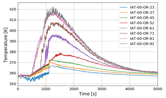
Figure 19.
Temperature distributions along a center line for the SP5 test.
The time period of the SPARC-PAR experiments can be divided into a hydrogen release period (phase-1) and a period after hydrogen release (phase-2). During the phase-1 in the SPARC-PAR experiments, hydrogen distributions in the SPARC vessel is very similar to normal distribution of a hydrogen release in a compartment, where a maximum concentration exists near an outlet of the hydrogen jet. After the hydrogen release stops in a compartment without PARs, the gas mixture with a maximum concentration of hydrogen locates at the top of the compartment due to the buoyancy of the hydrogen mixture. Figure 20 shows the change of the hydrogen concentrations along the center line of the SPARC vessel for the SP5 test. On the contrary to the normal behavior of the hydrogen distribution in phase-2, the hydrogen concentrations at the region below the PARs placed in the SPARC vessel (H2, H3, and H4) does not decrease below the values at H7, H10, H12, and H14 which locate above the PARs (seen in Figure 7). This confirms that the phenomenon of the hydrogen stratification induced by PAR appears.
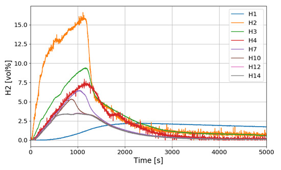
Figure 20.
Hydrogen concentration distributions along a center line for the SP5 test.
Another interesting thing found in the SPARC-PAR experiment is that the hydrogen concentration at the location below the hydrogen injection nozzle (H1) continuously increases and reaches the highest value finally, which is also thought to be induced by the PAR activation. The change in hydrogen concentration at the inlets and outlets of the two PARs installed in the SPARC vessel according to the time of the SP5 test is shown in Figure 21. It must be noted that the reduction of hydrogen concentration at the outlet of the PAR means initiation of its hydrogen depletion. The hydrogen concentration at the outlet of the right upper PAR (H11) reduces faster than the left lower PAR.
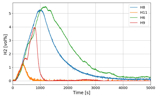
Figure 21.
Hydrogen concentrations at inlet and outlet of the PAR for the SP5 test, H6, H9: inlet and outlet of the left lower PAR, H8, H11: inlet and outlet of the right upper PAR.
Figure 22 shows the gas velocities entering the PARs measured by the vane wheel anemometers installed at the inlet of the PARs. The continuous flow was measured earlier at the inlet of the right upper PAR than the left lower PAR. The start time of the continuous inflow is very similar to the start time of the steep reduction of the outlet hydrogen concentration.
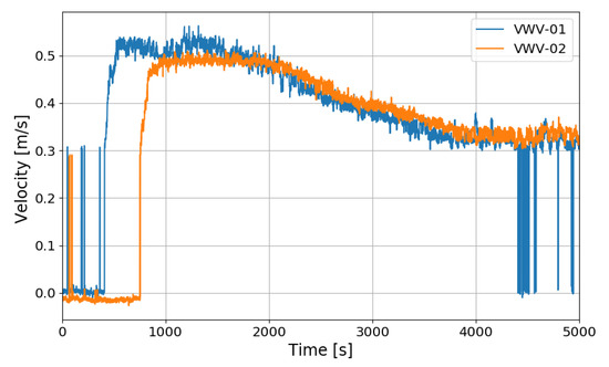
Figure 22.
Gas velocities at the inlet of the PARs for the SP5 test, VWV-01: the right upper PAR, VWV-02: the left lower PAR.
Figure 23 shows the change in the hydrogen depletion rate of the PARs in the SP5 test. It is seen that the hydrogen removal rate of PAR rises up to about 0.18 g/s. As described above, the correlation of the hydrogen removal rate of PAR is expressed as a function of the hydrogen concentration at the inlet.
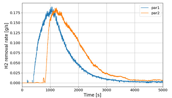
Figure 23.
Change of hydrogen removal rates of the PARs in the SP5 test.
If it is said that the hydrogen stratification induced by PARs occurs after the hydrogen injection is stopped, Figure 23 depicts that the PARs are continuously removing the hydrogen stratified at the lower region in the vessel. It is also seen that the lower PAR is more actively removing the hydrogen during the period of the hydrogen stratification (phase-2).
The most serious condition expected from the hydrogen stratification due to PARs is that the stratified hydrogen existing far below the PARs is no more entering the PAR inlets and the PARs cannot remove the hydrogen anymore. On the contrary, the SPARC-PAR experiments show that the stratified hydrogen below the PARs is continuously inhaled by the PARs. From Figure 24 which shows temperature behaviors on catalytic bodies of the PARs for the SP5 test, it is thought that the suction of the hydrogen stratified below the PARs into the PARs is caused by the heated catalytic bodies because the hot catalytic bodies can drive natural convection of the gas through the PAR chambers.
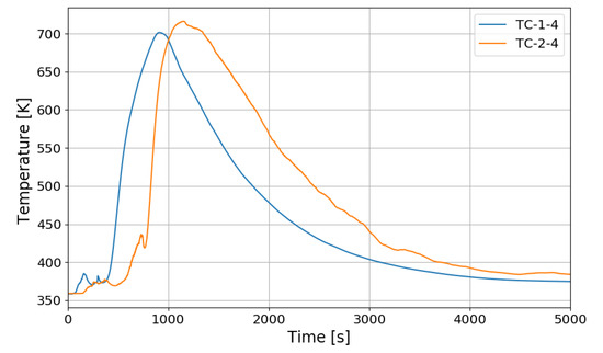
Figure 24.
Temperature behaviors on catalytic plates of the PARs for the SP5 test.
5.4. Visualization of Hydrogen Stratification
It is possible to expect the occurrence of the phenomenon of the hydrogen stratification by comparing the concentrations along the measuring points as shown in Figure 11, Figure 16, and Figure 20. However, a great deal of effort is required to understand the global structure of hydrogen stratification characteristics. In this study, a software tool has been developed to three-dimensionally visualize experimental data by adopting a method of mapping solutions from a coarse mesh to a fine mesh, which is well applied in computational fluid dynamics (CFD).
The probed data in the SPARC-PAR experiments are considered as solutions on a coarse mesh. Then the data can be easily mapped on a real mesh which is considered as a fine mesh. It is necessary to convert the experimental data to a designed data format before mapping. The software tool for the 3-D visualization is composed of a python program as a pre-processor to convert data format and a C++ program to map the data to a real mesh and export solutions to be visualized at user-specified time steps. Currently ParaView-5.8.0 [26] is used as a 3-D visualization software.
Figure 25 is the three-dimensional visualization of the distributions of temperature and hydrogen concentration at 400, 800, 1200, and 1600 s in the SP1 test, where contour plots on a plane with the PARs depict temperature distributions and the other contour plots show the hydrogen distributions. It is very intuitive to understand the hydrogen behaviors affected by temperature distributions. In Figure 25a, the distribution of hydrogen in the vessel shows the highest concentration near the injection nozzle while the hydrogen is being injected. In Figure 25c it is seen that the hydrogen gas mixture still remains in the lower region of the SPARC vessel even after the hydrogen injection is stopped. It is also found that the concentration of the stratified hydrogen is continuously reduced if Figure 25c,d are compared.
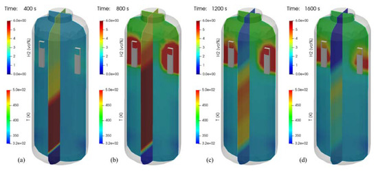
Figure 25.
Visualization of hydrogen and temperature distributions for the SP1 test (temperature contours on a plane crossing the PARs). (a) at 400 s; (b) at 800 s; (c) at 1200 s; (d) at 1600 s.
Figure 26 shows the distributions of the hydrogen and temperature at 500 s after end of hydrogen injection. In the tests of SP1, SP3, and SP5, the phenomenon that hydrogen is stratified in the lower region of the SPARC vessel by the PARs is clearly shown in the figure. This figure confirms that the hydrogen stratification occurs independently of the PAR configurations but the period and strength of the stratification is dependent on the PAR locations.
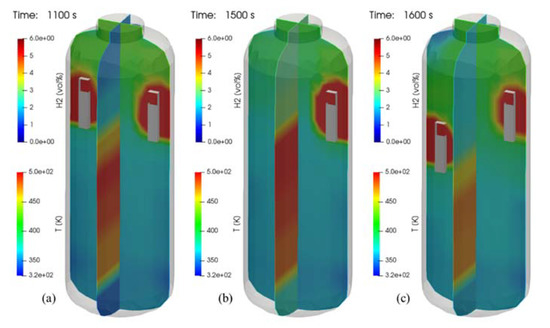
Figure 26.
Contours of hydrogen and temperature at 500 s after end of hydrogen injection (temperature contours on a plane crossing the PARs), (a) SP1 test, (b) SP3 test, and (c) SP5 test.
6. Conclusions
Currently PARs are applied to many nuclear power plants because of the passive characteristics, but there exist issues related to PAR’s hydrogen control in a containment. One of the issues is hydrogen stratification in which hydrogen is not well-mixed in a compartment due to the high temperature of exhaust gas emitted from the PAR and hydrogen that is accumulated in the lower part of the compartment.
In this study, an experimental simulation has been performed to evaluate the possibility of stratification of hydrogen by PARs in containment buildings using the SPARC test facility. When the PAR exhaust gas with high temperature is accumulated in the upper part of the test vessel by the operation of the PAR, it was confirmed that the hydrogen gas mixture could be stratified in the lower part of the test vessel for a period of time. In addition, it was found that the hydrogen mixture gas that stratified in the lower part of the test vessel can be gradually removed by the PARs. It is thought that the main cause for the gradual removal of the hydrogen accumulated in a lower part of the test vessel is a thermal inertia of the PARs, which is from the heat capacity of the catalytic body. The thermal inertia of the catalytic body that takes time to be heated and cooled and can make a buoyant force which creates the inhalation of the hydrogen mixture gas stratified under the PARs installed in the test vessel.
Author Contributions
Conceptualization, J.K.; Methodology, S.H., K.H.P., J.H.K., and J.Y.O.; Software, J.K. and S.H.; Validation, S.H.; Formal Analysis, J.K.; Investigation, K.H.P., J.H.K., and J.Y.O.; Resources, S.H.; Data Curation, S.H.; Writing—Original Draft Preparation, J.K.; Writing—Review & Editing, J.K.; Visualization, J.K.; Supervision, J.K.; Project Administration, J.K.; Funding Acquisition, J.K. All authors have read and agreed to the published version of the manuscript.
Funding
This work was supported by the National Research Foundation of Korea (NRF) grant funded by the Korea government (Ministry of Science, ICT) (No. 2017M2A8A4015277).
Acknowledgments
The authors would like to thank Sanjeev Gupta working for Becker technologies who shared the idea to evaluate the PAR depletion rate.
Conflicts of Interest
The authors declare no conflict of interest. The funders had no role in the design of the study; in the collection, analyses, or interpretation of data; in the writing of the manuscript, and in the decision to publish the results.
References
- US-NRC. Combustible Gas Control for Nuclear Power Reactors, NRC Regulations 10CFR 50.44. Available online: https://www.nrc.gov/reading-rm/doc-collections/cfr/part050/part050-0044.html (accessed on 2 September 2020).
- Korea Institute of Nuclear Safety. Safety Review Guidelines for Light Water Reactors (Revision 6); KINS/GE-N001; Korea Institute of Nuclear Safety: Daejeon, Korea, 2016. [Google Scholar]
- IAEA. Mitigation of Hydrogen Hazards in Severe Accidents in Nuclear Power Plants; IAEA-TECDOC-1661; International Atomic Energy Agency: Wien, Austria, 2011. [Google Scholar]
- OECD/NEA. Status Report on Hydrogen Management and Related Computer Codes; Nuclear Safety NEA/CSNI/R(2014) 8 June 2014; OECD/NEA: Issy-les-Moulineaux, France, 2014. [Google Scholar]
- Arnould, F.; Bachellerie, E.; Auglaire, M.; Boeck, B.; Braillard, O.; Eckardt, B.; Ferroni, F.; Moffett, R. Goethem. State of the Art on Hydrogen Passive Autocatalytic Recombiner. In Proceedings of the 9th International Conference of Nuclear Engineering, Nice, France, 8–12 April 2001. [Google Scholar]
- IAEA. Mitigation of Hydrogen Hazards in Water Cooled Power Reactors; IAEA-TECDOC-1196; International Atomic Energy Agency: Wien, Austria, 2001. [Google Scholar]
- Kim, J.; Hong, S.W. Development of a Numerical Method for PAR Analysis; Technical Report KAERI/TR-5759; Korea Atomic Research Institute: Daejeon, Korea, 2014. [Google Scholar]
- Westinghouse. AP1000 Pre-Construction Safety Report, UKP-GW-GL-732. 2010. Available online: https://www.namrc.co.uk/wp-content/uploads/2011/04/AP1000-safety-report.pdf (accessed on 1 March 2015).
- AREVA Passive Autocatalytic Recombiner. Available online: http://us.areva.com/home/liblocal/docs/Solutions/literature/G-008-V1PB-2011-ENG_PAR_reader.pdf (accessed on 1 September 2019).
- Kelm, S.; Jahn, W.; Reinecke, E.-A. Operational Behavior of Catalytic Recombiners—Experimental Results and Modelling Approaches. In Proceedings of the workshop on Experiments and CFD Code Application to Nuclear Reactor Safety XCFD4NRS, Computational Fluid Dynamics in Nuclear Reactor Safety, Grenoble, France, 10–12 September 2007. [Google Scholar]
- Bachellerie, E.; Arnould, F.; Auglaire, M.; Boeck, B.; Braillard, O.; Eckardt, B.; Ferroni, F.; Moffett, R. Generic Approach for Designing and Implementing a Passive Autocatalytic Recombiner PAR-System in Nuclear Power Plant Containments. Nucl. Eng. Des. 2003, 221, 151–165. [Google Scholar] [CrossRef]
- Dewit, W.A.; Koroll, G.W.; Sitar, L. Hydrogen Recombiner Development at AECL, AECL-1172 NEA/CSNI(96)8; Atomic Energy of Canada Limited: Chalk River, ON, Canada, 1996. [Google Scholar]
- Passive Autocatalytic Recombiner (PARs), SNC-LAVALIN AECL. Available online: www.snclavalin.com/nuclear (accessed on 1 September 2020).
- Park, J.W.; Koh, B.R.; Suh, K.Y. Demonstrative testing of honeycomb passive autocatalytic recombiner for nuclear power plant. Nucl. Eng. Des. 2011, 241, 4280–4288. [Google Scholar] [CrossRef]
- Kim, C.H.; Sung, J.J.; Ha, S.J.; Yeo, I.S. Analysis Method for the Design of a Hydrogen Mitigation System with Passive Autocatalytic Recombiners in OPR1000, PBNC2014-072. In Proceedings of the 19th Pacific Basin Nuclear Conference (PBNC 2014), Vancouver, BC, Canada, 24–28 August 2014. [Google Scholar]
- Kanzleiter, T.; Gupta, S.; Fischer, K.; Ahrens, G.; Langer, G.; Kühnel, A.; Poss, G.; Langrock, G.; Funke, F. Hydrogen and Fission Product Issues Relevant for Containment Safety Assessment under Severe Accident Conditions; Final Report OECD-NEA THAI Project; Organisation for Economic Co-operation and Development/Nuclear Energy Agency: Paris, France, 2010. [Google Scholar]
- Reinecke, E.-A.; Bentaib, A.; Kelm, S.; Jahn, W.; Meynet, N.; Caroli, C. Open Issues in the Applicability of Recombiner Experiments and Modeling to Reactor Simulations. Prog. Nucl. Energy 2010, 52, 136–147. [Google Scholar] [CrossRef]
- Meynet, N.; Bentaib, A. Numerical Study of Hydrogen Ignition by Passive Auto-Catalytic Recombiners. Nucl. Technol. 2012, 178, 17–28. [Google Scholar] [CrossRef]
- Gupta, S.; Kanzleiter, T.; Poss, G. Passive Auto-Catalytic Recombiners PAR Induced Ignition and the Resulting Hydrogen Deflagration Behavior in LWR Containment, NURETH-16. In Proceedings of the 16th International Topical Meeting on Nuclear Reactor Thermal Hydraulics, Chicago, IL, USA, 31 August 2015. [Google Scholar]
- Rozen, A. Simulation of Start-up Behavior of a Passive Autocatalytic Hydrogen Recombiner. Nucleonika 2018, 63, 27–41. [Google Scholar] [CrossRef]
- Simon, B.; Reinecke, E.-A.; Kubelt, C.; Allelein, H.-S. Start-up Behavior of a Passive Auto-catalytic Recombiner under Counter Flow Conditions: Results of a First Orienting Experimental Study. Nucl. Eng. Des. 2014, 278, 317–322. [Google Scholar] [CrossRef]
- Reinecke, E.A.; Tragsdorf, I.M.; Gierling, K. Studies on innovative hydrogen recombiners as safety devices in the containments of light water reactors. Nucl. Eng. Des. 2004, 230, 49. [Google Scholar] [CrossRef]
- Kim, J.; Kim, H.T.; Hong, S. Data Analysis of SPARC Experiment for PARs Installed in a Nuclear Reactor Containment; Technical Report KAERI/TR-8015; Korea Atomic Research Institute: Daejeon, Korea, 2020. [Google Scholar]
- Kim, J.; Kim, H.T.; Park, R.-J. Research on a Hydrogen Stratification Induced by PARs Installed in a Containment. In Proceedings of the Transactions of the Korean Nuclear Society Autumn Meeting, Yeosu, Korea, 25–26 October 2018. [Google Scholar]
- Gupta, S. Personal Communication; Becker Tech.: Pune, India, 2018. [Google Scholar]
- ParaView by Kitware. Available online: www.paraview.org (accessed on 1 September 2020).


Publisher’s Note: MDPI stays neutral with regard to jurisdictional claims in published maps and institutional affiliations. |
© 2020 by the authors. Licensee MDPI, Basel, Switzerland. This article is an open access article distributed under the terms and conditions of the Creative Commons Attribution (CC BY) license (http://creativecommons.org/licenses/by/4.0/).