Article

An Overview of MnAl Permanent Magnets with a Study on Their Potential in Electrical Machines

1
Division of Solid State Physics, Uppsala University, 752 36 Uppsala, Sweden
2
Division of Electricity, Department of Engineering Sciences, Uppsala University, 752 36 Uppsala, Sweden
3
Division of Physics and Astronomy, Uppsala University, 752 36 Uppsala, Sweden
4
Division of Electrical Machines and Power Electronics, Chalmers University of Technology, 412 96 Göteborg, Sweden
*
Author to whom correspondence should be addressed.
Energies 2020, 13(21), 5549; https://doi.org/10.3390/en13215549
Submission received: 8 July 2020 / Revised: 19 October 2020 / Accepted: 20 October 2020 / Published: 23 October 2020

Abstract

:
In this paper, hard magnetic materials for future use in electrical machines are discussed. Commercialized permanent magnets used today are presented and new magnets are reviewed shortly. Specifically, the magnetic MnAl compound is investigated as a potential material for future generator designs. Experimental results of synthesized MnAl, carbon-doped MnAl and calculated values for MnAl are compared regarding their energy products. The results show that the experimental energy products are far from the theoretically calculated values with ideal conditions due to microstructure-related reasons. The performance of MnAl in a future permanent magnet (PM) generator is investigated with COMSOL, assuming ideal conditions. Simplifications, such as using an ideal hysteresis loop based on measured and calculated saturation magnetization values were done for the COMSOL simulation. The results are compared to those for a ferrite magnet and an NdFeB magnet. For an ideal MnAl hysteresis loop, it would be possible to replace ferrite with MnAl, with a reduced weight compared to ferrite. In conclusion, future work for simulations with assumptions and results closer to reality is suggested.

1. Introduction

Upcoming technologies for a future electrified and sustainable society demand high awareness of the materials in use. Several materials are seen as critical with regards to sustainability [1]. The environmental impact of the rare earth element (REE) industry is evident in different parts of the process, both in the mining and the refining. In the mining industry, it may not be the impact of the REEs themselves, but instead, of other minerals found in the same deposit sites. In refining, there can be emissions in milling, in separation, or in later parts of processing the mineral into a useful metal [2,3].
Another important problem with REEs is the risk around availability [4]. Indicative of this is high and unstable price, which has been the case throughout the last few decades [5]. The situation has been linked to dominance from actors with a strong market power, who are able to control the price and supply [4]. REE mining had historically been dominated by the American Mountain Pass mine, until the 1990s. China has grown since then to become the number one producer, both in REE mining and refining. Even though almost all production is in China, there are several other unused reserves in other countries. There are still many reserves in the USA, and other big reserves in India, Brazil, Australia, Vietnam and Russia, but these are not used to the same extent [6]. An alternative European finding has also been proposed in Norra Kärr near the lake of Vättern in Sweden [7].
Many of the applications of REEs are associated with green technology such as wind power and electric vehicles. This has caused some researchers to warn of a crisis, due to the future development of a dependency on REEs [1,4,8]. One important usage of REEs is for permanent magnet materials such as NdFeB and SmCo, used in generators and electric motors.
Building generators for renewable energy technologies involves making decisions on materials to match the system requirements. Moreover, with the increasing interest in electric vehicles, new electric motors are designed with goals such as high efficiency, low cost, and high reliability. Motors for electric vehicles were previously reviewed in [9].
Magnetic materials made of neodymium-iron-boron (NdFeB) are often included in generators and motors. Permanent magnets (PMs) for electrical machines should preferably have a high remanence, high energy density, and should withstand demagnetization due to external fields and temperature. Two groups of frequently used magnets that match these requirements are hard ferrite and rare-earth (RE) magnets (e.g., NdFeB magnets) [9,10]. Concerns regarding performance, cost, the environment, and social standards affect the magnet chosen for the specific application. In a report by Schlör [11], the social footprint of RE materials for PMs was studied, and concluded that some PM production sites caused a social risk. Thus, research on new magnetic materials has been of great interest, investigating alternative combinations of materials which could generate the desired magnetic field and overall performance. This is reflected in the scientific literature. For example, RE-free PMs were reviewed by Cui et al. [12] as well as by Li et al. [13]. Wind power generators without RE magnets were discussed by Khazdozian, Hadimani, and Jiles [14], and strategies to change to these were reviewed in Pavel et al. [15]. Moreover, the recycling of NdFeB magnets from generators was discussed by Kumari et al. [16]. A review on RE-free electric vehicles was presented in Riba et al. [17], and an electric vehicle ferrite PM motor was described in Gennaro et al. [18]. Research on generators for renewable energy with RE-free PMs is presented by Eklund, Eriksson and Sjökvist in [19,20,21].
It is therefore of great interest to find alternative materials for PMs without REE. The main alternatives today are hexagonal structured ferrites, which have both a stable availability and a low price. There is, however, a large gap between NdFeB and ferrite in key aspects, such as the energy product (BHmax). This serves as a possibility for new hard magnetic materials that could cover this gap [22]. Here, MnAl is seen as having potential for filling this role.
In this paper, potential hard magnetic materials for electrical machines are in focus. Specifically, the compound MnAl [23] is evaluated as a potential magnetic material for generators. The methodology of the work is to utilize experimentally obtained data on MnAl as an input for simulations on different generators, and to compare the results with simulations on a generator including ferrites or NdFeB magnets. Thus, no experiments on electrical machines are included. The paper is structured as follows: firstly, theory and background to PM materials for electrical machines are presented. Thereafter, the method used for the analysis of future MnAl magnets for electrical machines is presented. This is followed by the results from the simulations. Finally, the discussion and conclusions are presented, suggesting some future research directions for MnAl magnets for electrical machines. This initial study on MnAl for generators is limited, for example, there are limitations due to the accuracy of the simulations, no full experiments are included, and only a few types of generators are studied. This suggests that more research could be performed in the future.

2. Theory and Background

2.1. Behavior and Properties of Linear Permanent Magnets

A permanent magnet (PM) in an electrical machine will be operating at a point in the second quadrant of the B vs. H hysteresis curve. The second quadrant is the region where the magnetization and flux density remain positive (M > 0, B > 0), but the magnetic field is negative (H < 0). Naturally, generator design focuses on this part of the curve. This specific section is often referred to as the demagnetizing curve. The PM remains magnetized in the desired direction while the magnetic field strength is working in an opposite direction. The magnetic field strength here is caused by the currents in the electrical machine and by the impact of the demagnetizing field from the magnet itself. The principle of electrical machines, i.e., generators and motors, is described by Faraday’s law of induction:
U = N d Φ dt   ,
where U is the induced voltage, N is the number of turns in the coil, and d Φ / d t   is the time-varying magnetic flux which can be induced by either electromagnets or PMs. The magnetic flux density of hard magnetic materials with constant permeability in the operation region can be described by the following equation:
B ( H ) = μ 0 μ r H + B r   ,
where μ 0 is the permeability of free space, μ r is relative permeability, and H is the applied field [17]. Magnets with non-linear permeability after reaching a critical demagnetization operate in the demagnetizing curve and enter a reversal curve that creates a minor loop: a so-called recoil curve. This curve is often approximated by a recoil line, i.e., a linear model of a minor loop. The trajectory of the reversal curve or the linear model points towards a new lower residual magnetic flux density (remanence), Br,rec or Br,new. When the magnetic field increases up to zero, it reaches a new lower remanence flux density [24]. The linearization of the recoil line is called recoil permeability, µrec. This permeability should not, however, be confused with the more common permeability that is used to model soft magnetic materials. In a soft magnetic material, the hysteresis is usually neglected, and the linear model of the permeability (µ) crosses the origin for alternating applied fields. In models of hard magnetic materials the recoil permeability, µrec, is used in combination with an offset, the remanence Br,rec. The model for hard non-linear magnetic materials could thereby be written as
B ( H ) = μ 0 μ rec H + B r , rec .
The recoil permeability would be µrec = 1 for an ideal PM with constant magnetization. The recoil permeability is near 1, or assumed to be 1 for many common materials such as NdFeB, SmCo and ferrites. However, some materials have a significant demagnetization, such as Alnico, with deviating recoil curves and higher recoil permeability. In those cases, it is more complicated to conduct a linear approximation.
The PM characteristics in Table 1 are often relevant when designing electrical machines [25,26]. Other important aspects are chemical, mechanical and thermal properties, and cost. Furthermore, the second quadrant of the B vs. H hysteresis loop (H < 0, B > 0) is of high importance.
NdFeB (general composition Nd2Fe14B) and SmCo (which is manufactured in two compositions: SmCo5 and Sm2Co17) are two different kinds of RE magnet alloys based on the RE metals Nd and Sm. Sm2Co17 has higher Hci values than SmCo5 and thus offers greater inherent stability.
NdFeB was invented in the 1980s and is popular in electrical machines due to its properties corresponding very well to those desired in electrical machines [26], which also explains the increasing demand. However, its Curie temperature (Tc) is only about 310 °C and magnetocrystalline anisotropy constant (K1) is negligible at 150 °C, which of course limits the operating temperature. Another major drawback with NdFeB is that it contains critical raw materials, which has led to large price fluctuations since its invention.
Ceramic magnets, also known as hard ferrite magnets (general composition BaO:6Fe2O3 or SrO:6Fe2O3), have been used commercially since the 1950s thanks to their low cost. Their energy product is low, at least six times smaller than for NdFeB magnets, therefore a larger mass is needed in order to compensate. This limits the range of applications where they can be used.

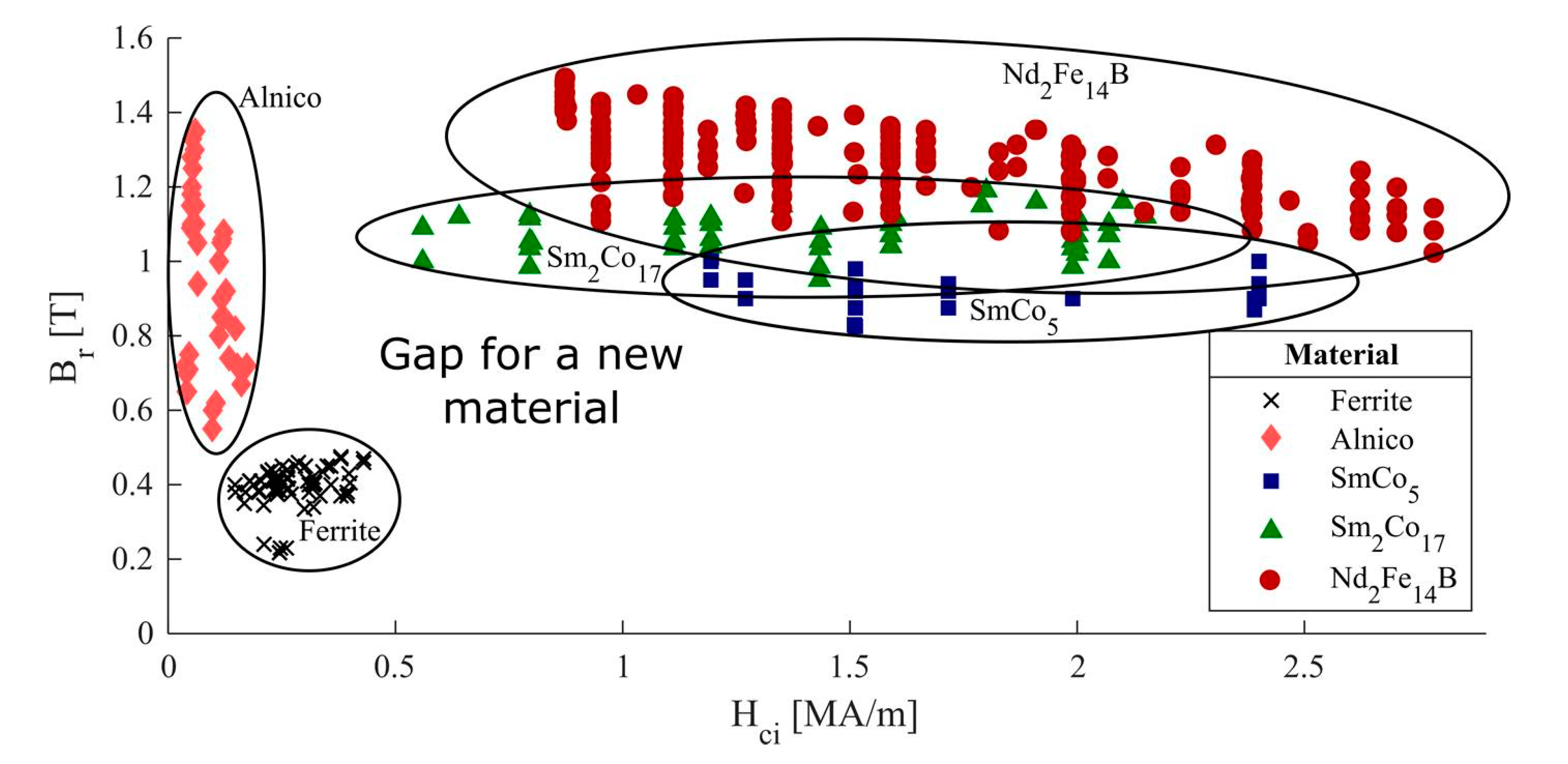
2.2. Materials That Could Be Used in Future Electrical Machines

In the PM research field it is current interestto fill the gap, in terms of performance of the magnets, between ferrite and RE magnets, as can be seen in Figure 1. A new magnet with an appropriate price/performance ratio of not more than about 1 $/J is suggested to be suitably economically efficient [22,29,30]. A material with those properties could enhance the performance and reduce the weight of devices that currently include ferrites, and decrease the cost of devices that include RE magnets. Currently, bonded RE magnets, i.e., composites with PM powder embedded in a plastic matrix, can partially fill the gap but at a high cost. One approach for plugging the gap between ferrites and NdFeB is to replace Nd with less expensive elements. Ce-substituted NdFeB and SmCo compounds and their alloys have been investigated [31] and show promising cost-to-performance results. Ce is regarded as an RE metal but is still relatively abundant, making up 66 ppm of the earth’s crust, comparing to 41 ppm for Nd [32]. Materials that could be possible candidates for filling the gap are discussed in Mohapatra [33] and Coey [22]. Among the candidates are FePt, FeNi, Co-carbide, Fe-nitride, ZrCo11, HfCo7, Y2Fe14B and YCo5, along with Mn-based compounds such as MnBi, Mn2Ga and MnAl.
The MnAl τ-phase [23,33,34] that was first reported by Kono [35] and Koch [36] in the late 1950s has been suggested as a potential replacement for ferrites as a PM [37]. Mohapatra, on the other hand, claims that in order to compete with ferrite magnets and spread their field of application, improved PM attributes are still required [33]. In the review presented by Patel [38], it is concluded that Mn-based magnetic alloys (MnBi, MnAl and MnGa) have shown potential as alternatives for the replacement of RE magnetic materials, even though a lot of work and effort is still required. In the composition range of 50–60 at. % Mn, the metastable τ-phase which is strongly ferromagnetic can be formed [33]. No other phases in the Mn–Al system are known to be ferromagnetic. With the intrinsic properties of saturation magnetization (Ms) of 0.62 T (493 kA/m) [33], a Curie temperature (Tc) of 285–380 °C [33,39], and a magnetocrystalline anisotropy constant (K1) of 1.7 MJ/m3 [23], τ-phase MnAl has the potential for becoming a PM with high coercivity and a high energy product at elevated temperatures. Alloying with carbon has shown positive effects on stabilizing the τ-phase [12,23,40,41] and it has been reported that the material was heated and kept at 200 °C for several weeks without significant effects on the magnetic properties [42]. This result differs, but is not completely opposing to the results presented in the review by McCallum [43]. Fazakas et al. reported that repeated heating up to 500° C did not affect the magnetic properties of MnAlC significantly [40]. MnAl has a low cost thanks to abundant raw materials, good resistance to corrosion and a low density (5000–5100 kg/m3) [23,40].
There are also alternatives to the addition of carbon, such as MnAl doped with Cu, Fe, Ni, Co, Cr, Ti, Mo, B, Zn or Ga [12,44]. Some alloys among these of interest are MnAl with boron [44,45] and MnAl with gallium [46].

3. Experimental Data for MnAl

3.1. Energy Product and Coercivity for MnAl

The energy product, (BH)max, has been the figure of merit for PMs for a long time. It is also often used to denote the grade of the magnet. Usually, (BH)max represents the experimental or commercial value, whereas (BH)MAX represents the theoretically calculated potential energy product, where (BH)max < (BH)MAX. Here are some examples of how the energy product can be calculated for a potential replacement material, MnAl. The potential energy product for an ideal rectangular hysteresis loop with µ0Hc0Ms/2 can be described by
B H M A X = µ 0 M s 2 4
where Ms is the saturation magnetization in A/m [22]. MnAl and MnAlC data from Fang et al. [23] was converted from cgs units (emu/g) to SI (A/m) through multiplication with the density 5100 kg/m3, giving the volume magnetization, and thereby also the Ms in A/m, for all the samples. The magnetic flux density, B, of the sample was calculated through B = µ0(Hi + M) where Hi = H – NM, where H is the applied field, N is the demagnetization factor of the sample and M is the magnetization. N was estimated to be 0.5, approximating a spherical shape for the non-compacted powder particles. The field terms were converted to SI units through the relationship 1 G ≈ 1 Oe = 1000/(4π) A/m. The experimental energy product BHi was plotted vs. B for values in the second quadrant of the measured B:H loops, giving the experimental BHmax values of all samples.
A true PM can be made in any desired shape, which means that coercivity must exceed the saturation magnetization: Hc > Ms [22]. However, this is not even the case for the best magnets today and there is always a need for compromises. The results coming out of this simplified case will be optimistic but aim to show the upper limits for the material’s potential.
In order to study how the material would work in a realistic situation, a sample with relatively high magnetization and coercivity should have been chosen for this study. However, the experimental energy products are still very low, making the modelling somewhat difficult. Instead, some simplifications have been made, and focus is put on the best possible scenario of MnAl, assuming ideal conditions with square hysteresis loops and µr = 1.
The maximum coercivity, Hc,MAX, can be calculated through
H c , M A X = 2 K 1 µ 0 M s ,
where K1 is the magnetocrystalline anisotropy constant of the material. Experimentally, materials always show Hc << Hc,MAX. The difference between theory and experiment is attributed to the effect of magnetic inhomogeneities and explained by Brown’s paradox [47].

3.2. Calculations on MnAl

The magnetization data published in [23,48] obtained by the authors at Uppsala University have been analyzed and some of the results are presented in Table 2 and Figure 2 and Figure 3. In Table 2, the experimental results have also taken non-magnetic phases into account to show the properties of the pure τ–phase.
The calculated Ms was slightly lower than that presented by Park [34], and resulted in a theoretical energy product of 153 kJ/m3. The samples with the same doping and treatment were compared to each other and the highest energy product results of each sample group are presented in Figure 2. The sample groups have different optimal milling times and relaxation temperatures, since the optimal parameters are shown together with the sample name in the label. The best theoretical energy product was found for the as-prepared MnAlB sample with Ms = 75.8 emu/g = 387 kA/m and Mr = 42.0 emu/g = 214 kA/m, giving theoretical energy products of 47 kJ/m3 and 14 kJ/m3, respectively, in comparison to its experimental value of 12.3 kJ/m3. Considering nonmagnetic phases, the magnetization of the magnetic τ-phase was 123 emu/g, giving a theoretical energy product of 124 kJ/m3. However, this non-treated sample has almost no coercivity, and thus a value of the experimental energy product too low for commercial use. The sample with the highest coercivity, 5 251 Oe, is the 4 h ball-milled MnAl (cf. [23]). However, this sample has a quite low magnetization, 22.5 emu/g comparing to 88 emu/g (449 kA/m) and 111 emu/g (546 kA/m) for the non-treated MnAl and MnAlC, respectively. The high coercivity result is comparable to that presented by Rial [49] despite different process routes. According to Edström et al. [48], calculations showed that magnetocrystalline anisotropy constant K1 was at least 1.7 MJ/m3 and Ms equalled about 800 kA/m, giving an Hc,max of 338 kA/m for MnAl, according to Equation (4). This result is not surprising; it has been discussed in the literature that it is hard to achieve high coercivity for RE-free PMs while keeping high magnetization [12]. Furthermore, the results showed that the best experimental energy product was 11 kJ/m3 for the MnAlC sample that was milled for 2 h and then relaxed, compared to its theoretical energy product 72 kJ/m3 for Ms = 93.8 emu/g = 478 kA/m or 13 kJ/m3 for Mr = 39.5 emu/g = 201 kA/m. This can be compared to the commercial values of ferrite (Y40-grade) which only reach up to 42 kJ/m3, and NdFeB (N52-grade), that reaches up to 422 kJ/m3, respectively, where their theoretical values are 92 kJ/m3 (for Ms = 108 emu/g = 0.67 T [50]) and 510 kJ/m3 (for Js = 1.6 T), respectively.
(BH)MAX for the pure τ-phase reaches 153 kJ/m3 for calculated Ms = 137 emu/g = 698 700 A/m [48], but so far only 31.8–58.9 kJ/m3 has been achieved experimentally by other researchers [33,39,51,52]. Many of the best results were produced in the 1990s or much earlier and it is hard to find new results matching them, probably due to different processing routes, but also due to a lack of production of full density bulk products [38]. The difference in (BH)MAX for MnAl bulk (40–70 kJ/m3) and nanoparticles (38 kJ/m3) was presented by Jimenez-Villacorta and Lewis in 2013 [53]. There is a need for data of bulk samples of new PMs such as MnAl to be produced in order to generate good simulations.
For the simulation, the theoretically calculated value of Ms for MnAl (presented as case 1 in Section 4) and the experimental Ms value of MnAlC (presented as case 2 in Section 4) were chosen due to a superior Ms. The ideal hysteresis curves are explained in Section 3. In Figure 3, the experimental B   vs .   H i hysteresis curve is shown, specifically of the MnAl samples of the highest saturation magnetization, highest coercivity, and the highest energy product reached in the experiments.

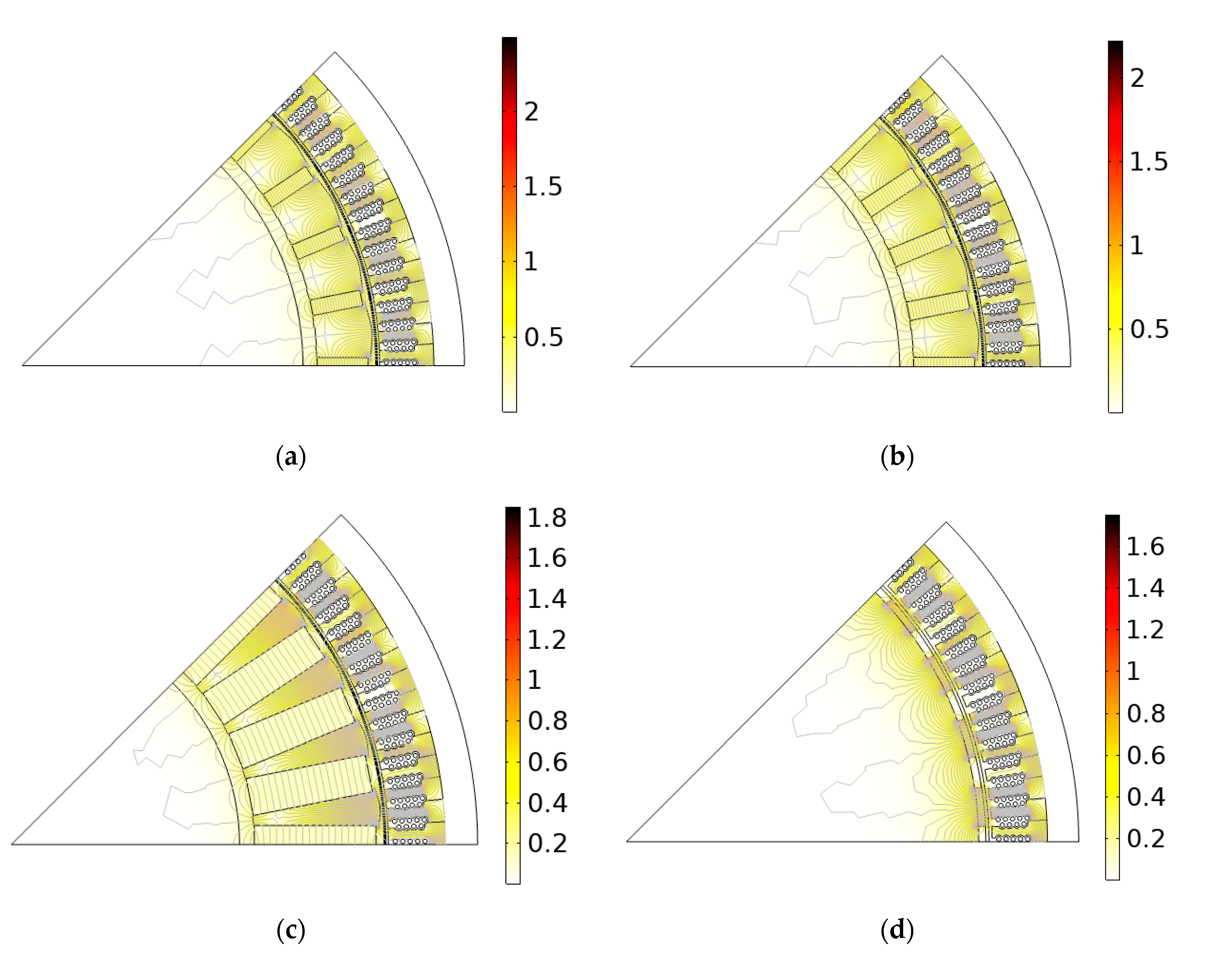
4. Simulations of Generators with Different PMs

In the following section, results from simulations of four generators with different PMs and the same geometry are presented and compared. The simulations were computed in COMSOL Multiphysics 5.4 software (https://www.comsol.com/). COMSOL Multiphysics uses the finite element method (FEM) to solve Maxwell’s equations by finding the magnetic potential. A 2D-model which simulated 45 degrees of the generator, i.e., 4 out of 32 poles, was used for computational efficiency. In the air gap, a moving boundary was added so that the machine did not need to be re-meshed for every time step due to the movement of the rotor. The PMs were simulated by setting the value and direction of Br, as well as μrec, as input parameters. For the iron in the stator and rotor, the non-linear BH curves were used in the simulations.
A permanent-magnet synchronous generator (PMSG) with MnAl magnets for case 1 and case 2 (see Table 2) was simulated to see if MnAl magnets could potentially be used as an alternative to NdFeB and ferrite magnets. Two main topologies (shown in Figure 4) were used for the modelling: a spoke-type generator with tangentially magnetized PMs [20] and a surface-mounted generator with radially magnetized PMs [54]. According to Eklund [27], the most optimal topology of the generator with MnAl PMs, with remanence below 0.9, for the chosen application was spoke-type (See Figure 4a,b), while for NdFeB the optimal topology was surface-mounted PMs. A spoke-type topology of the rotor has better protection from demagnetization of the PMs from the stator magnetic field due to the magnetization direction of the magnets. Magnetic flux in a spoke-type electrical machine is concentrated in poles, making it possible to use PMs with lower energy product without increasing the rotor diameter. Simulation of the electrical machine with a rotor topology that is not suggested for its PM type could decrease the performance of the machine. The simulated PMSG has previously been studied both through simulations and experiments with a spoke-type rotor with ferrite (Y40) magnets (See Figure 5c) [20,55] and surface-mounted NdFeB (N40) magnets (See Figure 5d) [54].
The magnet height and the air gap height for the generator with NdFeB magnets [54] have both been decreased to have the same air gap as the other generators. All four cases had the same stator parameters as stated in Table 3, and all of the PMSGs had a rated speed of 127 rpm and an electrical frequency of 33.867 Hz to simplify the further comparison of the generators. The internal resistance of the generator was 0.15 ohms per phase and the load resistance was 3.5975 Ohm. More information about the stator and other aspects of the generator can be found in [20,55].
The heights and widths of the PMs were chosen such that the output voltage with no load was the same for all the simulated generators, so the generators would have different rotor geometry, PM volume, and PM weight. The aim for all generators was to have a no-load voltage of approximately 220 V. Output voltages, with and without a load, as well as output power for all four generators (cases) are presented in Table 4. The inner part of the rotor was assumed to be from non-magnetic material, and it was simulated as air in the model. In spoke-type generators, iron between permanent magnets is added to create a path for magnetic flux, to form rotor poles and to hold magnets.
In Figure 5a,d, the simulated topology is presented for the four different cases. Figure 5a–c are spoke-type generators and (d) is surface-mounted. Note the different size of the PMs due to the different values of the (BH)max. The density, volume and weight of PMs affects the size and inertia of the generator and can be of great importance for a structure. The rotors with MnAl are heavier than the rotor with NdFeB, but much lighter than the rotor with ferrite PMs, as stated in Table 4. Figure 5 shows the size difference of the PMs, and that the magnetic flux is quite similar on the stator side.

5. Discussion

After analyzing and comparing all magnetization data and energy products for all samples, it can be concluded that the highest experimental energy product (BH)max, 11 kJ/m3 was achieved for the MnAlC sample that was milled for 2 h and then relaxed. This powder sample has not been oriented or compacted to a bulk magnet and the final value of its energy product has not yet been confirmed. Deformation of the crystal grains and where texture is induced, e.g., through hot compaction, could result in anisotropy and higher remanence and energy product. The process of making a bulk magnet from powder is not straight-forward, and requires dedicated and synergic interdisciplinary research carried out by experienced teams of metallurgists, computational experts and material engineers and researchers, especially when it comes to obtaining PMs from non-equilibrium synthesis and processing techniques. To the authors’ knowledge, and what was also concluded by Cui [12], the early achievements of the 1960s and 1970s have still not been surpassed. Our samples have not been further alloyed with other constituents that could enhance the magnetic properties. However, there is reason to believe that an increased energy product could be achieved by such production steps [12,53]. For the higher energy product (BH)max, a smaller volume of the magnet is needed. In this work, the point for (BH)max was selected as a fixed working point for the material, which is a simplification. For simplicity, the curve was considered to be linear at this point and the recoil permeability was the permeability at (BH)max. Mr gives an estimation of the (BH)max that is closer to the achieved experimental results, while Ms shows the potential (BH)max including many assumptions of a perfect material. In other words, the results are not supposed to predict the near future performance of the material. This is a preliminary study to show the potential of the material for a given design. The potential energy product of the pure τ-phase reaches 153 kJ/m3, but so far only about 30% of that value has been achieved.
The validity of the results greatly depends on the difference in data from small grains of MnAl to a full bulk size of the magnet. There are still uncertainties around the difference in magnetic properties of small and large magnetic materials. Furthermore, material scientists tend to present data in cgs-units, which complicates calculations for electrical machines. If there is also a lack of necessary conversion factors, such as density, this can lead to inaccurate results in subsequent work. Frequently, the results are presented in tables or text instead of in full hysteresis curves, which would facilitate the simulation process. Furthermore, it is not always declared if (BH)max is calculated from Ms (Equation (3)) or taken from the hysteresis curve, resulting in possible misinterpretation of the results.
However, in order to calculate magnet performance in electrical machines, it is important to present not only intrinsic values but also values of Br and Hci. In order for interdisciplinary cooperation between researchers, the density of the materials should be presented for conversion from cgs to SI units. Of course, SI units would be preferred.
New magnets may have different strengths in different material properties. Besides magnetism, those properties which are most valuable for certain industrial purposes are still not fully described, and new materials are not always investigated regarding such properties.
Thus, there is a need to collaborate between different research fields. There may be benefits in investigating opportunities for new PMs in applications even at an early stage, to develop a better idea of which properties are desirable, and also to justify the research for future applications. It would save time, if the designs and models are ready when future PMs reach the proper levels for applications. In the case of MnAl, the metallurgy and magnetism of the τ-phase are remarkably complex. It took nearly two decades of research for MnAl magnets to achieve only half of the theoretical energy product and a modest coercivity [12,51].
It was decided not to simulate the third case of MnAl with Ms = Hc,max, since the characteristics of that case would give almost the same results as the ferrite case due to similar values of Br: 0.38 T for ferrite and 0.42 T for MnAl; µr = 1.08 for ferrite and 1 for MnAl; and finally, a density of 4900 kg/m3 and 5100 kg/m3 for MnAl. The higher Br for MnAl would be compensated by its lower µr and higher density compared to the ferrite. However, it is not impossible that in the future MnAl samples of higher remanence could be produced keeping the same coercivity, or that another material with better properties (higher Br, higher Hc or lower density) will be discovered. Better MnAl results have been presented in the past, hopefully, they can be reproduced or even surpassed, resulting in machine simulation results somewhere between the ferrite and the results for MnAl in this study.

6. Conclusions and Future Work

Ongoing electrification in many different fields requires new magnetic materials, with properties that compete with ferrites, when it comes to both performance and weight. This study indicates that other magnetic materials, such as MnAl, could be interesting for further investigation for their use in electrical machines, such as motors in electric vehicles or in generators. The results show that the replacement of ferrites with, for example, MnAl, could lead to substantial weight reduction. For the potential (BH)MAX of MnAl, the weight could be reduced to 20% compared to ferrite. The lower weight could be important, especially for motors in electric vehicles, noting that a future study could include simulations with motors. There is still a long way to go to achieve a high coercivity and a temperature-stable bulk magnet for this specific material. Future studies could also include experimental work to evaluate the potential opportunity to use MnAl in motors or generators.
In order for more detailed studies of MnAl performance in electrical machines, high energy product materials are needed with complete hysteresis curve graphs, either from calculations or experiments. Future work could include optimizing the simulation models for non-linear behavior and µr ≠1. It was considered that the working point was fixed in this work. In a more detailed study, it could be possible to take into consideration that the working point might be moving.
Many more aspects of the electrical machine should also be examined in future studies. Important factors which have not been included in these initial simulations are thermal properties, mechanical stability, and demagnetization. Before an eventual experimental verification, all of these properties should be simulated. This paper focuses on MnAl, but future research could provide a broader and deeper presentation on the current usefulness of different PM materials in electrical machines.
Other materials that were suggested earlier in the paper would be likely candidates in this study. By showing the potential of MnAl in future electrical machines, the authors intend to motivate further research on RE-free PM materials, not yet reaching the levels of commercial use, and to encourage more detailed interdisciplinary studies on the subject.

Author Contributions

Conceptualization, S.K., J.L., A.E.F., M.L. and S.E.; Data curation, S.K., A.I., G.M. and L.S.; Formal analysis, S.K., A.I. and G.M.; Funding acquisition, M.L.; Investigation, S.K. and A.I.; Methodology, S.K., G.M. and L.S.; Project administration, S.K.; Resources, P.S. and M.L.; Software, S.K., A.I., A.E.F. and L.S.; Supervision, K.G., P.S., M.L. and S.E.; Validation, S.K., K.G. and S.E.; Visualization, S.K., A.I., G.M. and L.S.; Writing—original draft, S.K., A.I., J.L., G.M. and A.E.F.; Writing—review & editing, S.K., A.I., K.G., P.S., M.L. and S.E. All authors have read and agreed to the published version of the manuscript.

Funding

The research was funded by Uppsala University and the Swedish strategic research program StandUp for Energy.

Conflicts of Interest

The authors declare no conflict of interest. The funders had no role in the design of the study; in the collection, analyses, or interpretation of data; in the writing of the manuscript, or in the decision to publish the results.

References

  1. Hofmann, M.; Hofmann, H.; Hageluken, C.; Hool, A. Critical raw materials: A perspective from the materials science community. Sustain. Mater. Technol. 2018, 17. [Google Scholar] [CrossRef]
  2. Haque, N.; Hughes, A.; Lim, S.; Vernon, C. Rare earth elements: Overview of mining, mineralogy, uses, sustainability and environmental impact. Resources 2014, 3, 614–635. [Google Scholar] [CrossRef] [Green Version]
  3. Weng, Z.H.; Jowitt, S.M.; Mudd, G.M.; Haque, N. Assessing rare earth element mineral deposit types and links to environmental impacts. Trans. Institutions Min. Metall. Sect. B Appl. Earth Sci. 2014, 122, 83–96. [Google Scholar] [CrossRef]
  4. Smith Stegen, K. Heavy rare earths, permanent magnets, and renewable energies: An imminent crisis. Energy Policy 2015, 79, 1–8. [Google Scholar] [CrossRef]
  5. Eriksson, S.; Bernhoff, H. Rotor design for PM generators reflecting the unstable neodymium price. In Proceedings of the 2012 20th International Conference on Electrical Machines, ICEM 2012, Marseille, France, 2–5 September 2012; pp. 1419–1423. [Google Scholar]
  6. Balaram, V. Rare earth elements: A review of applications, occurrence, exploration, analysis, recycling, and environmental impact. Geosci. Front. 2019, 10, 1285–1303. [Google Scholar] [CrossRef]
  7. Schreiber, A.; Marx, J.; Zapp, P.; Hake, J.F.; Voßenkaul, D.; Friedrich, B. Environmental impacts of rare earth mining and separation based on eudialyte: A new European way. Resources 2016, 5, 32. [Google Scholar] [CrossRef] [Green Version]
  8. Alonso, E.; Sherman, A.M.; Wallington, T.J.; Everson, M.P.; Field, F.R.; Roth, R.; Kirchain, R.E. Evaluating rare earth element availability: A case with revolutionary demand from clean technologies. Environ. Sci. Technol. 2012, 46, 3406–3414. [Google Scholar] [CrossRef]
  9. De Santiago, J.; Bernhoff, H.; Ekergård, B.; Eriksson, S.; Ferhatovic, S.; Waters, R.; Member, S.; Leijon, M. Electrical Motor Drivelines in Commercial All-Electric Vehicles: A Review. IEEE Trans. Veh. Technol. 2012, 61, 475–484. [Google Scholar] [CrossRef] [Green Version]
  10. Tripathi, S.M.; Tiwari, A.N.; Singh, D. Grid-integrated permanent magnet synchronous generator based wind energy conversion systems: A technology review. Renew. Sustain. Energy Rev. 2015, 51, 1288–1305. [Google Scholar] [CrossRef]
  11. Schlör, H.; Zapp, P.; Marx, J.; Schreiber, A.; Venghaus, S.; Hake, J.-F. The social footprint of permanent magnet production based on rare earth elements-a social life cycle assessment scenario. Energy Procedia 2017, 142, 984–990. [Google Scholar] [CrossRef]
  12. Cui, J.; Kramer, M.; Zhou, L.; Liu, F.; Gabay, A.; Hadjipanayis, G.; Balasubramanian, B.; Sellmyer, D. Acta Materialia Current progress and future challenges in rare-earth-free permanent magnets. Acta Mater. 2018, 158, 118–137. [Google Scholar] [CrossRef]
  13. Li, D.; Li, Y.; Pan, D.; Zhang, Z.; Choi, C.J. Prospect and status of iron-based rare-earth-free permanent magnetic materials. J. Magn. Magn. Mater. 2019, 469, 535–544. [Google Scholar] [CrossRef]
  14. Khazdozian, H.A.; Hadimani, R.L.; Jiles, D.C. Development of rare earth free permanent magnet generator using Halbach cylinder rotor design. Renew. Energy 2017, 112, 84–92. [Google Scholar] [CrossRef]
  15. Pavel, C.C.; Thiel, C.; Degreif, S.; Blagoeva, D.; Buchert, M.; Schüler, D.; Tzimas, E. Role of substitution in mitigating the supply pressure of rare earths in electric road transport applications. Sustain. Mater. Technol. 2017, 12, 62–72. [Google Scholar] [CrossRef]
  16. Kumari, A.; Kumar, M.; Pramanik, S.; Kumar, S. Recovery of rare earths from spent NdFeB magnets of wind turbine: Leaching and kinetic aspects. Waste Manag. 2020, 75, 486–498. [Google Scholar] [CrossRef]
  17. Riba, J.; López-Torres, C.; Romeral, L.; Garcia, A. Rare-earth-free propulsion motors for electric vehicles: A technology review. Renew. Sustain. Energy Rev. 2016, 57, 367–379. [Google Scholar] [CrossRef] [Green Version]
  18. De Gennaro, M.; Jürgens, J.; Zanon, A.; Gragger, J.; Schlemmer, E.; Fricassè, A.; Marengo, L.; Ponick, B.; Trancho, E.; Kinder, J.; et al. Designing, prototyping and testing of a ferrite permanent magnet assisted synchronous reluctance machine for hybrid and electric vehicles applications Interior Permanent Magnet machine United States of America. Sustain. Energy Technol. Assess. 2019, 31, 86–101. [Google Scholar] [CrossRef]
  19. Eklund, P.; Eriksson, S. Air Gap Magnetic Flux Density Variations due to Manufacturing Tolerances in a Permanent Magnet Synchronous Generator. In Proceedings of the 2016 XXII International Conference on Electrical Machines (ICEM), Lausanne, Switzerland, 4–7 September 2016. [Google Scholar]
  20. Eklund, P.; Sjökvist, S.; Eriksson, S.; Leijon, M. A Complete Design of a Rare Earth Metal-Free Permanent Magnet Generator. Machines 2014, 2, 120–133. [Google Scholar] [CrossRef] [Green Version]
  21. Sjökvist, S.; Eklund, P.; Eriksson, S. Determining demagnetisation risk for two PM wind power generators with different PM material and identical stators. IET Electr. Power Appl. 2016, 10, 593–597. [Google Scholar] [CrossRef] [Green Version]
  22. Coey, J.M.D. Permanent magnets: Plugging the gap. Scr. Mater. 2012, 67, 524–529. [Google Scholar] [CrossRef]
  23. Fang, H.; Ångström, J.; Cedervall, J.; Svedlindh, P.; Gunnarsson, K.; Sahlberg, M. Directly obtained τ -phase MnAl, a high performance magnetic material for permanent magnets. J. Solid State Chem. 2016, 237, 300–306. [Google Scholar] [CrossRef]
  24. Hornfeck, A.J.; Edgar, R.F. The Output and Optimum Design of Permanent Magnets Subjected to Demagnetizing Forces. Electr. Eng. 1940, 59, 1017–1024. [Google Scholar] [CrossRef]
  25. Pyrhönen, J.; Jokinen, T.; Hrabovcová, V. Design of Rotating Electrical Machines; John Wiley & Sons: Hoboken, NJ, USA, 2008; ISBN 9780470695166. [Google Scholar]
  26. Rahman, M.; Slemon, G. Promising applications of neodymium boron Iron magnets in electrical machines. IEEE Trans. Magn. 1985, 21, 1712–1716. [Google Scholar] [CrossRef]
  27. Eklund, P.; Eriksson, S. The influence of permanent magnet material properties on generator rotor design. Energies 2019, 12, 1314. [Google Scholar] [CrossRef] [Green Version]
  28. Coey, J.M.D. Permanent magnet applications. J. Magn. Magn. Mater. 2002, 248, 441–456. [Google Scholar] [CrossRef]
  29. Skomski, R.; Coey, J.M.D. Magnetic anisotropy—How much is enough for a permanent magnet? Scr. Mater. 2016, 112, 3–8. [Google Scholar] [CrossRef] [Green Version]
  30. Coey, J.M.D. Hard magnetic materials: A perspective. IEEE Trans. Magn. 2011, 47, 4671–4681. [Google Scholar] [CrossRef]
  31. Orimoloye, K.; Ryan, D.H.; Pinkerton, F.E.; Medraj, M. Intrinsic magnetic properties of Ce2Fe14B modified by Al, Ni, or Si. Appl. Sci. 2018, 8, 205. [Google Scholar] [CrossRef] [Green Version]
  32. Smith, K.S.; Huyck, H.L.O. An overview of the abundance, relative mobility, bioavailability, and human toxicity of metals. Rev. Econ. Geol. Environ. Geochem. Miner. Depos. 1999, 6A,B, 29–73. [Google Scholar] [CrossRef]
  33. Mohapatra, J.; Liu, J.P. Rare-Earth-Free Permanent Magnets: The Past and Future, 1st ed.; Elsevier B.V.: Amsterdam, The Netherlands, 2018. [Google Scholar]
  34. Park, J.H.; Hong, Y.K.; Bae, S.; Lee, J.J.; Jalli, J.; Abo, G.S.; Neveu, N.; Kim, S.G.; Choi, C.J.; Lee, J.G. Saturation magnetization and crystalline anisotropy calculations for MnAl permanent magnet. J. Appl. Phys. 2010, 107, 1–4. [Google Scholar] [CrossRef]
  35. Kōno, H. Erratum: “On the Ferromagnetic Phase in Manganese-Aluminum System”. J. Phys. Soc. Jpn. 1959, 14, 237. [Google Scholar] [CrossRef]
  36. Koch, A.J.J.; Hokkeling, P.; v.d. Steeg, M.G.; De Vos, K.J. New material for permanent magnets on a base of MNnd AL. J. Appl. Phys. 1960. [Google Scholar] [CrossRef]
  37. Crew, D.C.; McCormick, P.G.; Street, R. MnAl and MnAlC permanent magnets produced by mechanical alloying. Scr. Metall. Mater. 1995, 32, 315–318. [Google Scholar] [CrossRef]
  38. Patel, K.; Zhang, J.; Ren, S. Rare-earth-free high energy product manganese-based magnetic materials. Nanoscale 2018, 10, 11701–11718. [Google Scholar] [CrossRef]
  39. Pareti, L.; Bolzoni, F.; Leccabue, F.; Ermakov, A.E. Magnetic anisotropy of MnAl and MnAlC permanent magnet materials. J. Appl. Phys. 1986, 59, 3824–3828. [Google Scholar] [CrossRef]
  40. Fazakas, E.; Varga, L.K.; Mazaleyrat, F. Preparation of nanocrystalline Mn-Al-C magnets by melt spinning and subsequent heat treatments. J. Alloys Compd. 2007, 434–435, 611–613. [Google Scholar] [CrossRef]
  41. Zeng, Q.; Baker, I.; Cui, J.B.; Yan, Z.C. Structural and magnetic properties of nanostructured Mn-Al-C magnetic materials. J. Magn. Magn. Mater. 2007, 308, 214–226. [Google Scholar] [CrossRef]
  42. Chaturvedi, A.; Yaqub, R.; Baker, I. Microstructure and magnetic properties of bulk nanocrystalline MnAl. Metals 2014, 4, 20–27. [Google Scholar] [CrossRef] [Green Version]
  43. McCallum, R.W.; Lewis, L.; Skomski, R.; Kramer, M.J.; Anderson, I.E. Practical aspects of modern and future permanent magnets. Annu. Rev. Mater. Res. 2014, 44, 451–477. [Google Scholar] [CrossRef]
  44. Sakka, Y.; Nakamura, M.; Hoshimoto, K. Rapid Quenching and Properties of Hard Magnetic Materials in MnAI-X (X = Ti, Cu, Ni, C, B) Systems. Available online: https://link.springer.com/article/10.1007/BF00544507 (accessed on 8 July 2020).
  45. Kamino, K.; Kawaguchi, T.; Nagakura, M. Magnetic Properties of MnAl System Alloys. IEEE Trans. Magn. 1966, 2, 506–510. [Google Scholar] [CrossRef]
  46. Mix, T.; Bittner, F.; Müller, K.H.; Schultz, L.; Woodcock, T.G. Alloying with a few atomic percent of Ga makes MnAl thermodynamically stable. Acta Mater. 2017, 128, 160–165. [Google Scholar] [CrossRef]
  47. Kronmüller, H. Theory of Nucleation Fields in Inhomogeneous Ferromagnets. Phys. Status Solidi 1987, 144, 385–396. [Google Scholar] [CrossRef]
  48. Edström, A.; Chico, J.; Jakobsson, A.; Bergman, A.; Rusz, J. Electronic structure and magnetic properties of L10 binary alloys. Phys. Rev. B - Condens. Matter Mater. Phys. 2014, 90, 1–5. [Google Scholar] [CrossRef] [Green Version]
  49. Rial, J.; Palmero, E.M.; Bollero, A. Efficient Nanostructuring of Isotropic Gas-Atomized MnAl Powder by Rapid Milling (30 s). Engineering 2020, 6, 173–177. [Google Scholar] [CrossRef]
  50. Chikazumi, S. Physics of Ferromagnetism, 2nd ed.; Oxford University Press: New York, NY, USA, 1997; Volume 66, ISBN 0198517769. [Google Scholar]
  51. Ohtani, T.; Kato, N.; Kojima, S.; Kojima, K.; Sakamoto, Y.; Konno, I.; Tsukahara, M.; Kubo, T. Magnetic properties of Mn-Al-C permanent magnet alloys. IEEE Trans. Magn. 1977, 13, 1328–1330. [Google Scholar] [CrossRef]
  52. Yanagitani, A.; Okawa, A.; Tanaka, Y. Characteristics of MnAlC Rapidly Solidified Powders. 1994. Available online: https://www.sciencedirect.com/science/article/abs/pii/0921509394908621 (accessed on 7 August 2020).
  53. Jimenez-Villacorta, F.; Lewis, L.H. Advanced Permanent Magnetic Materials. In Nanomagnetism; 2014; Available online: https://www.onecentralpress.com/wp-content/uploads/2014/12/CHAPTER-7-MG-23-LATEST.pdf (accessed on 6 September 2020).
  54. Eriksson, S.; Solum, A.; Leijon, M.; Bernhoff, H. Simulations and experiments on a 12 kW direct driven PM synchronous generator for wind power. Renew. Energy 2008, 33, 674–681. [Google Scholar] [CrossRef]
  55. Eklund, P.; Sjolund, J.; Berg, M.; Leijon, M.; Eriksson, S. Experimental Evaluation of a Rare Earth-Free Permanent Magnet Generator. IEEE Trans. Energy Convers. 2020, 8969, 1. [Google Scholar] [CrossRef]
Figure 1. Different PM materials available on the market and their properties, illustrating the gap between ferrites and rare-earth (RE) magnets.
Energies 13 05549 g001
Figure 2. Energy product (BH) curves of MnAl and C-, B-, Ga-doped MnAl. The black lines are milled samples, and the red lines are milled and relaxed samples.
Energies 13 05549 g002
Figure 3. Hysteresis curves of the MnAl samples: (a) B vs. Hi curves; (b) M vs. Hi curves.
Energies 13 05549 g003
Figure 4. Generator topologies: (a) Spoke-type (b) Surface-mounted. 1. Permanent magnet, 2. Rotor pole 3. Stator slots with coils 4. Air gap.
Energies 13 05549 g004
Figure 5. Topology of the generators and magnetic flux density [T]: (a) Case 1; (b) Case 2; (c) Hard ferrite; (d) NdFeB.
Energies 13 05549 g005
Table 1. Some properties of permanent magnets (PMs) relevant to electrical machines.
QuantitySymbol [unit]NdFeBSmCoFerriteAlnicoReference
RemanenceBr [T]1.08–1.490.87–1.190.20–0.460.55–1.37[27]
Intrinsic coercivityHci [kA/m]876–27101350–2400140–40538–151[27]
Relative permeabilityµr [-]1.0–1.11.0–1.11.05–1.21.3–6.2[27]
Energy product(BH)max [kJ/m3]220–430143–2516.4–41.810.7–83.6[27]
DensityD [kg/dm3]7.4–7.58.2–8.54.9–5.16.8–7.31, 2
Electrical resistivityρ [nΩm]12–1650–60 or 530–900107–1011470–7501, 3, 4, 5
Curie temperatureTc [°C]310720–820450800[28]
Maximal operation temperatureTmax [°C]150250–350300500[28]
1 Standard Specifications for Permanent Magnet Materials. https://allianceorg.com/pdfs/MMPA_0100-00.pdf. 2 Samarium Cobalt Magnets, SmCo Magnets Datasheet. http://www.eclipsemagnetics.com/. 3 Ferrite Magnets / Ceramic Magnets Datasheet. https://www.eclipsemagnetics.com/. 4 NdFeB Magnets / Neodymium Iron Boron Magnets Datasheet. https://www.eclipsemagnetics.com/. 5 Characteristic physical properties of sintered NdFeB magnet material at 20 °C. https://neorem.fi/.
Table 2. Magnetic properties of calculated MnAl and experimental MnAl with an addition of carbon and boron.
MsMrHcBHMAX
µ0Ms2/4µ0Mr2/4Exp.Info
emu/gemu/gOekJ/m3kJ/m3kJ/m3
137N.A.N.A.153N.A.N.AMnAl, calculated by [48]
Chosen as CASE 1.
12316.96721242.32.0Drop synth. MnAlC by [23],
Only tauphase considered. 10% weight from nonmagnetic phases removed.
11115.26721011.91.6Drop synth. MnAlC by [23], highest exp. Ms.
Chosen as CASE 2.
12352.016581242218.6MnAlC
2 h ball-milled and relaxed from [23], 24% weight from nonmagnetic phases removed
75.8*42.03010471412.3MnAlB
90 min ball-milled and relaxed,
highest exp. (BH)max
11547.1275710818.115.6MnAlC, drop synth., 4 h milled and relaxed
from [23], 28% weight from nonmagnetic phases removed
83342757569.48.3Drop synth, 4 h milling and relaxed from [23]
Best result according to first author in [23].
Table 3. Stator parameters of the permanent-magnet synchronous generator (PMSG).
ParameterValue
Stator inner diameter [mm]760
Air gap height [mm]6.6
Length of the generator [mm]224
Number of slots per phase per pole [-]5/4
Rotational speed [rpm]127
Table 4. Rotor parameters of the PMSG.
ParameterMnAl
(Case 1)
MnAlC
(Case 2)
Y40 Ferrite
(Case 3)
N40 NdFeB
(Case 4)
Rotor type [-]Spoke typeSpoke typeSpoke typeSurface-mounted
Number of poles [-]32323232
PM height [mm]16.7620.14387.3
PM width [mm]54.0264.93122.540
Remanence Br [T]0.8780.7120.381.26
Recoil permeability µrec [-]111.07721.05
Density [kg/m3]5100510049007500
No-load RMS voltage [V]219.6219.2220.42219.9
Load RMS voltage [V]207.2207.6209.8208.9
Output power [W]11 93311 97712 13512 233
Weight of PMs [kg]33.147.8163.515.7
Publisher’s Note: MDPI stays neutral with regard to jurisdictional claims in published maps and institutional affiliations.

