Article

Experimental Study of Harmonic Influence on Electrical Energy Metering

by
Yaroslav Shklyarskiy
1,
Zbigniew Hanzelka
2 and
Aleksandr Skamyin
3,*
1
Department of General Electrical Engineering, Saint-Petersburg Mining University, 199106 Saint-Petersburg, Russia
2
Faculty of Electrical Engineering, Automatics, Computer Science and Biomedical Engineering, AGH University of Science and Technology, 30-059 Krakow, Poland
3
Department of Electric Power and Electromechanics, Saint-Petersburg Mining University, 199106 Saint-Petersburg, Russia
*
Author to whom correspondence should be addressed.
Energies 2020, 13(21), 5536; https://doi.org/10.3390/en13215536
Submission received: 12 September 2020 / Revised: 14 October 2020 / Accepted: 20 October 2020 / Published: 22 October 2020

Abstract

:
The paper considers the influence of harmonics on the operating of electrical energy meters in a network with nonlinear loads. It is shown that electronic static meters of active energy are tested in the presence of distortions, and electronic static meters of reactive energy accuracy requirements do not take into account the possible presence of harmonics. It is revealed that the maximum influence on the error in active energy metering is exerted by the number of harmonics taken into account and their amplitude, and the error in reactive energy metering is additionally influenced by the phase angle at the fundamental and harmonic frequencies, which has been confirmed in laboratory conditions. Additionally, experimental studies of the capacitor bank’s influence on reactive energy metering has been carried out in the presence of nonlinear electrical loads. It is shown that when capacitor banks are connected, the error in reactive energy measurement and variation range of the phase shift angle of harmonics significantly increases. The assessment of the computational error of reactive power metering according to various equations were carried out based on the field measurements. If the voltage and current distortion values do not exceed the permissible values, the error can be estimated at, at most, 5–7%.

1. Introduction

Currently, in many industrial enterprises, the main share in the cost of production accrues from electricity consumption costs [1,2,3]. This is particularly true for energy-intensive enterprises in the aluminum industry [4,5]. For instance, electricity consumption by the Bratsk Aluminum Smelter reaches 75% of the electricity generated at the Bratsk Hydroelectric Power Station, the installed capacity of which is 4500 MW [6]. When it comes to energy metering, an accurate reading is important since a fraction of a percent can end up equaling thousands of dollars. An additional problem is the presence of high harmonics generating both from grid and customer sides [7]. A number of publications note that the active power of harmonics can reach tens of kilowatts for some consumers [8,9]. In this context, the issues of electricity metering in the presence of distortions, calculating the parameters of power consumption, as well as contractual relations between consumers and electricity suppliers, are of the utmost importance.
Metering devices, whose readings are used when determining electricity consumption, must meet the legislative requirements for ensuring the uniformity of measurements, as well as the requirements of the wholesale and retail electricity markets. The latest European Measuring Instruments Directive states that the accuracy of metering devices for commercial purposes has to be verified in actual operating conditions [10]. Technical parameters and metrological characteristics of electronic electricity meters must meet the requirements of the relevant standards which relate to the static meters for active and reactive energy in accordance with the accuracy class. Herein, for electronic meters of active energy, an accuracy check is set in the presence of the fifth harmonic with a voltage amplitude of 10% and current amplitude of 40% [11,12]. Existing standards for reactive energy meters relate to their operation at sinusoidal voltages and currents, and the requirements for their accuracy do not take into account the possible presence of harmonics [13,14]. It should be noted that the previous Standard IEC 61268:1995 contained this type of test, and currently there are requirements for reactive energy meters only at the fundamental frequency [14]. Therefore, reactive energy meters, meeting the requirements of such standards, fail to satisfy their operating conditions in the presence of voltage and current distortions.
In case of sinusoidal voltage and current, various electronic meters give comparable readings for active and reactive energy in accordance with their accuracy class. However, due to increased voltage and current distortion’s levels in electrical networks, these meters are also used for measurements in the presence of harmonics. Under these conditions, different types of meters can give different readings. A number of publications on this subject contain the experimental studies of various types of meters [15,16], in which it is shown that the differences in the readings of the various types of meters can be significant. In [17], it is noted that consumers on the electrified railway pay less for electricity than consumers with a linear electrical load. Besides, different traction substations have different relative power errors because of different load properties.
Earlier publications [18,19] considered the differences in the readings of electromechanical and electronic meters. It was revealed that in active energy meters of the electromechanical type a flux weakening causes a large negative relative error in the registration of active harmonic energy. There was unexpected nonexistent energy when voltage and current harmonics in quadrature were applied to the meter. The paper [20] considers the error evolution in energy meters under voltage unbalance conditions in a wide range, from total balance to phase fault. In [21], the estimation of the active energy metering error of a class B meter was carried out under realistic and quasi-realistic harmonic disturbances. It was shown that that realistic harmonic disturbances affect significantly only some energy meters. However, in these works, the parameters of high harmonics were not revealed, which have the greatest impact on the error in active and reactive energy metering.
In addition, in terms of reactive energy metering, the results of theoretical studies are presented, which characterize the measurement error when calculating according to the existing power theories of various scientists [22,23]. Such conclusions are not of practical interest, since many of these theories are not applicable in practice. In the case of reactive energy metering, it is of interest to study the influence of reactive power compensation devices on electricity metering. The recently introduced standard [24] offers a new theory regarding the determination of power components in the presence of harmonics. However, it is noted that this is just another theory, distinct from the well-established concepts. On the basis of its application in measuring devices, it is possible to obtain new information that can give impetus to the development of the power theory for nonsinusoidal currents and voltages.
Thus, the aim of the research is to study the impact of harmonics and compensating devices on electricity metering using electronic energy meters, as well as to determine the parameters of harmonics and range of distortions that have the greatest impact on the metering error for active and reactive power.
This paper is structured in three main parts. In the first part, the influence of harmonic parameters on the measurement of active and reactive power by electronic electricity meters was studied in detail. In the second part, the influence of capacitor banks with different levels of reactive power compensation on the measurement of active and reactive power was studied. In the third part, an assessment of the computational error was carried out when taking into account reactive power measurement under realistic distorted voltages and currents at an industrial enterprise.

2. Research Methods

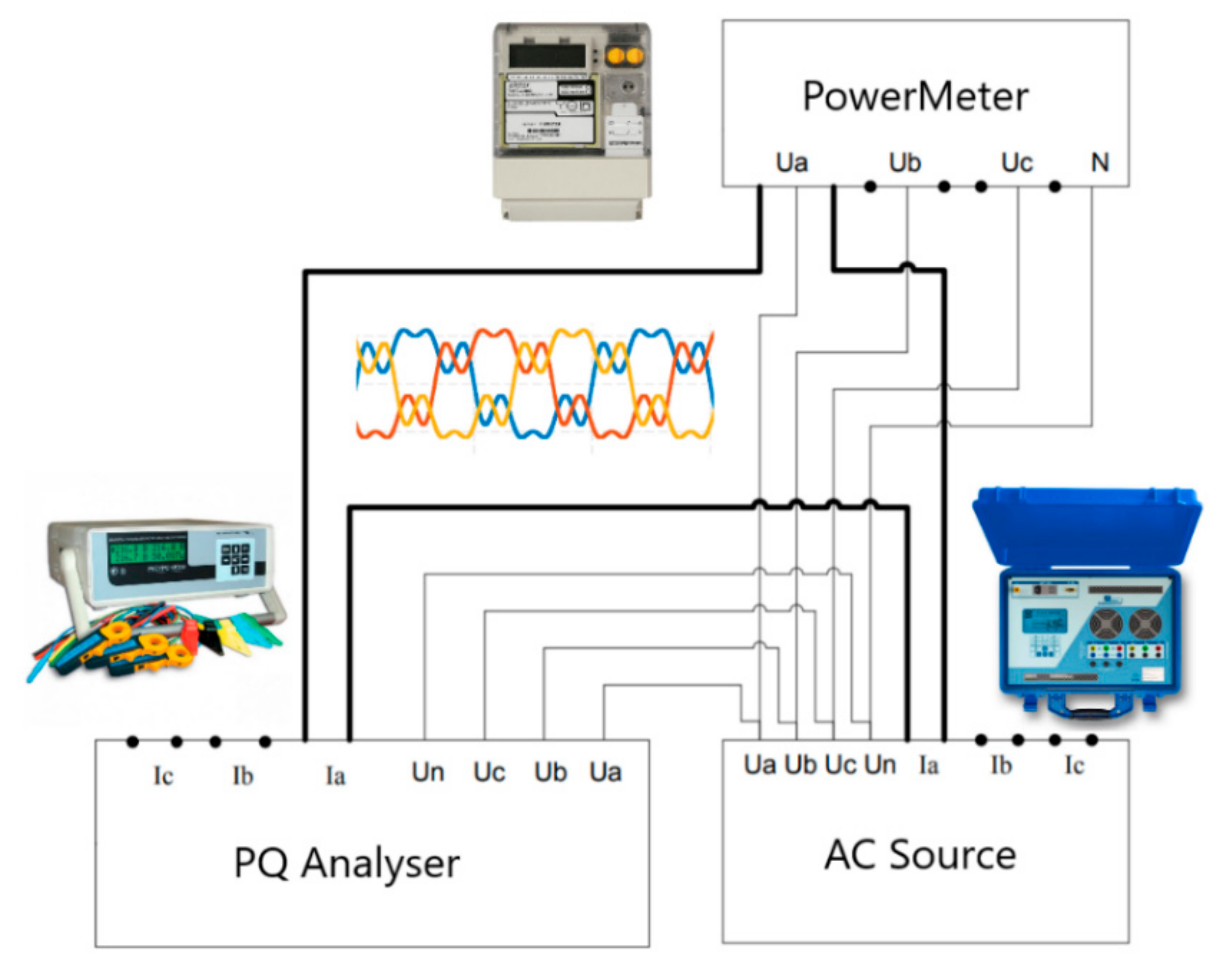
2.1. Influence of Harmonic Parameters on Power Measurement by Electronic Electricity Meters

This part of the research deals with determining the impact of the harmonic parameters, such as amplitude, spectrum, and phase angle, on the metering error for active and reactive power when using various metering devices. The study was performed using a laboratory bench with a programmable source of alternating current and voltage (AC Source) in star connection, which is used in the calibration of metering devices for active, reactive and apparent power and energy, including electricity meters. The block diagram of electrical connections between the equipment used is shown in Figure 1, where only one phase connection is indicated.
The equipment used in the laboratory research is presented in Table 1. Two electronic three-phase power meters (PMs) were tested. The power consumption readings were compared with readings from a reference power quality analyzer, Resurs UF2M (PQ analyzer).
The measurement program is presented in Table 2, where № is an experiment number. Herein, the harmonic phase voltage (Uh, V) and current amplitudes (Ih, A), phase shift angle (ϕh), spectrum of harmonics, as well as the phase shift angle at the fundamental frequency (ϕ1) were varied. The amplitudes of harmonics are presented as a percentage of the fundamental one, and the phase shift angle is presented in degrees. The values, presented as a fraction, are the varied parameters of harmonics.
For experiments with numbers 1–8, the values of the phase shift angle of harmonics were set as a result of preliminary modeling of the generalized network with linear, nonlinear electrical loads and reactive power compensation devices. This was carried out in order to identify the parameters of harmonics that are closest to real-life conditions. The experiments 1–4 correspond to the case of a connected external/internal nonlinear electrical load without capacitor banks. The experiments 5–8 correspond to the case of a connected external/internal nonlinear electrical load with capacitor banks.

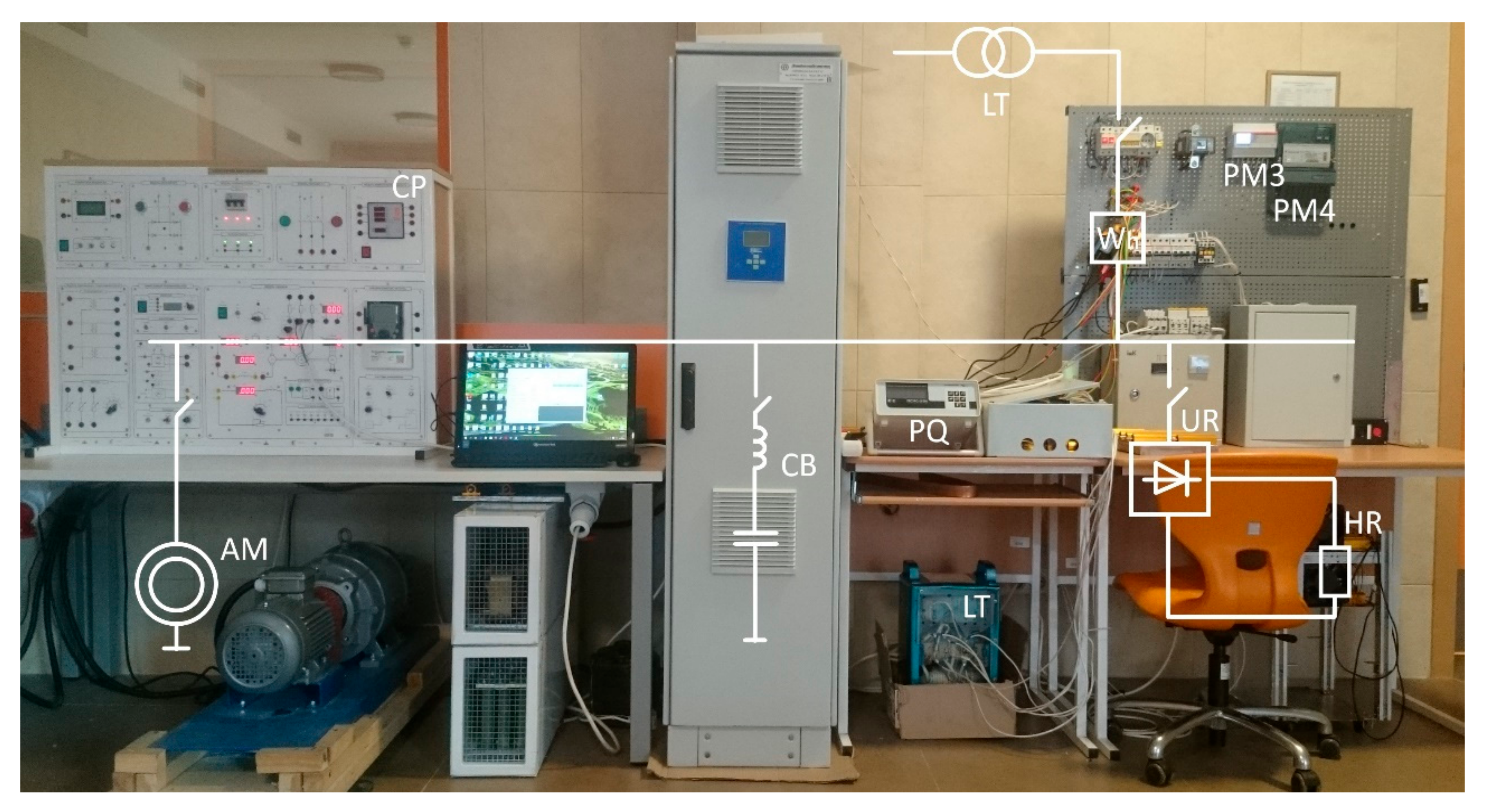
2.2. Influence of Capacitor Banks with Different Levels of Reactive Power Compensation on the Measurement of Active and Reactive Power

The second part of the research deals with determining the impact of harmonics on the metering error for active and reactive power in the presence of capacitor banks when using various metering devices. This kind of research appears to be expedient, since calculation of reactive power flows in the presence of harmonics still remains a matter of controversy and discussion [15,16,23,24,25], which will undoubtedly affect the readings of energy meters. The study was performed using the laboratory bench shown in Figure 2. The test bench is powered from the grid via a three-phase laboratory autotransformer (LT) and includes an asynchronous motor (AM) with a control panel (CP) (the load is a direct currentgenerator), a capacitor bank (CB) with an antiharmonic reactor, an uncontrolled three-phase rectifier (UR) with a load in the form heat resistance (HR).
Table 3 Various modes of test bench operation were set and readings were taken from the tested power meters PM3 and PM4. The power consumption readings were compared with readings from a reference power quality (PQ) analyzer, Resurs UF2M.
The measurement program provides 6 modes of operation with different compositions and parameters of load (Table 4).
Mode 1 corresponds to a connected AM at the idle and an uncontrolled three-phase rectifier. Mode 2 corresponds to mode 1 with connected capacitor banks (power factor of about 0.94, inductive mode). Mode 3 corresponds to mode 2 with reactive power overcompensation (power factor of about 0.92, capacitive mode). Modes 4, 5, 6 correspond to modes 1, 2, 3 with a connected load on the asynchronous motor shaft, respectively. For modes 5 and 6, the power factors are about 0.94 and 0.88, respectively.

2.3. Assessment of the Reactive Power Measurement under Realistic Distorted Voltages and Currents

The third part of the research deals with determining the computational error when taking into account reactive power measurements under realistic distorted voltages and currents at an industrial enterprise. The measurements were carried out at the input feeder of the enterprise at the point of connection to the low voltage (0.4 kV) distribution panel using a power quality analyzer according to various realizable equations with the capacitor banks connected and disconnected.

3. Results and Discussion

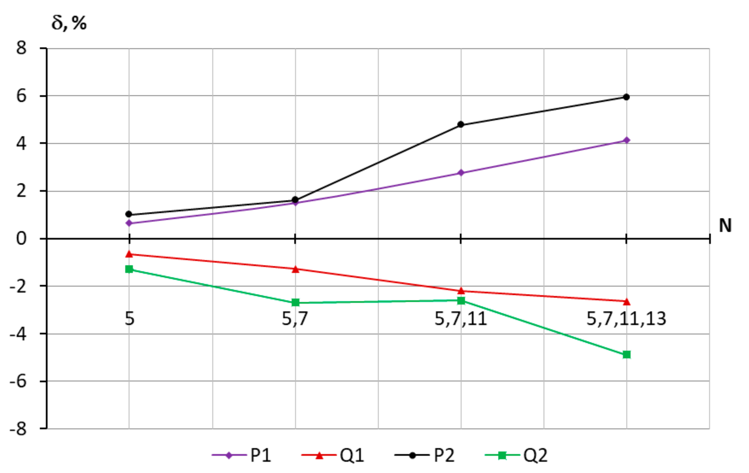
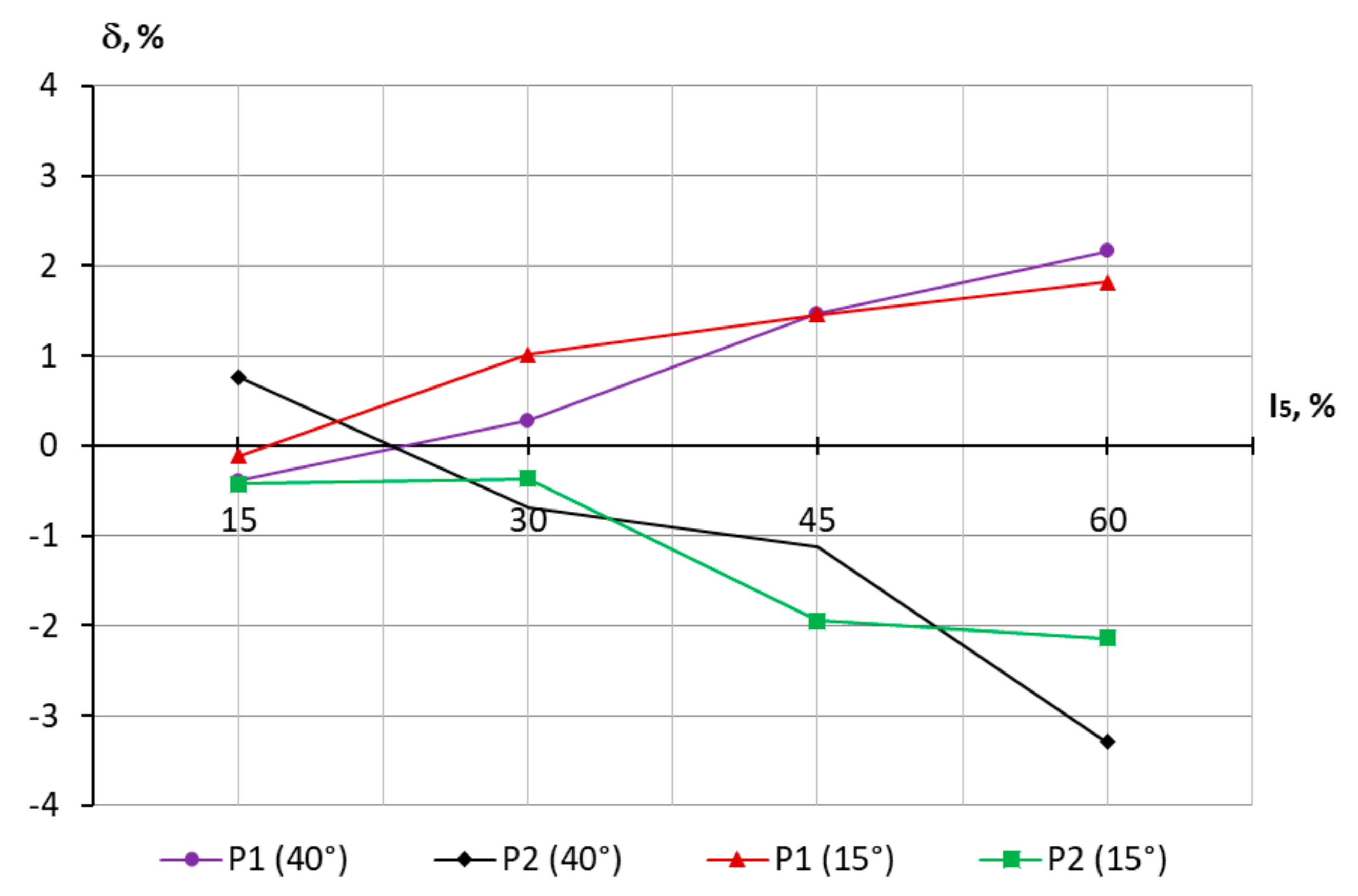
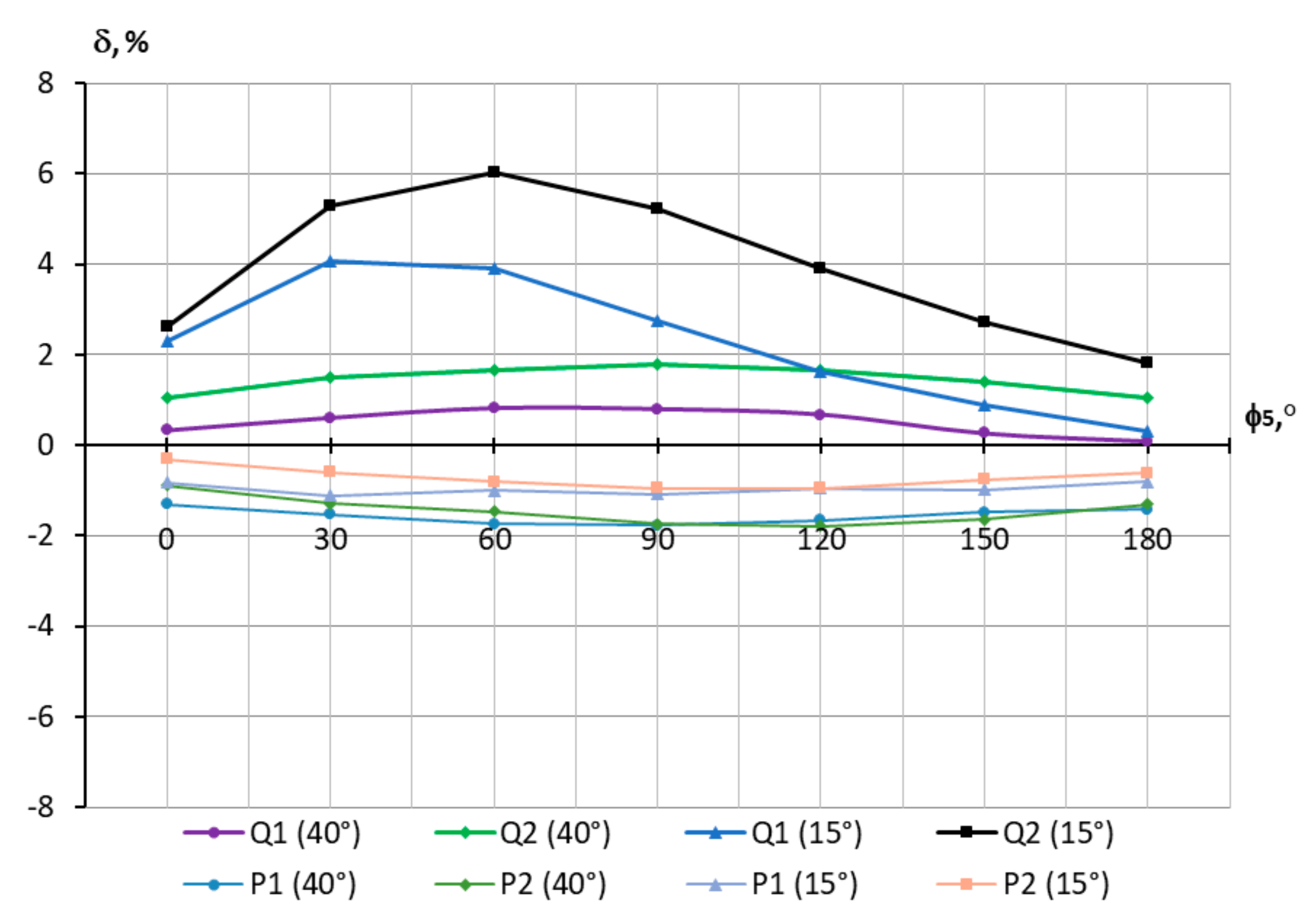
3.1. Influence of Harmonic Parameters on Power Measurement

Within the framework of the first part of the research, based on the data presented in Table 2, various current and voltage signals were generated to the PMs. In this case, the parameters of the harmonic current amplitude, harmonic current phase angle, phase shift angle at the fundamental frequency, as well as the spectrum composition of harmonics were changed. The programmable source has three channels for generating voltages and three independent channels for generating currents. The range of output phase voltages is from 60.12 to 268 V, the range of output currents is from 0.501 to 7.0 A, and the rated values of voltages and currents are 220 V and 5 A, respectively.
The PQ analyzer calculates the readings of active power in accordance with computational models in the tested devices, namely:
P = P1 + PH,
P 1 =   U 1 · I 1 · cos ϕ 1 ,   P H = h 1 U h · I h · cos ϕ h ,
where Uh is the rms value of voltage harmonic h, Ih is the rms value of current harmonic h, and ϕh is the phase shift angle between voltage and current harmonic h. The readings of reactive power are calculated as follows:
Q   =   S 2     P 2 ,   S   = h = 1 U h 2 · h = 1 I h 2 .
As a result, the dependences of the spectrum, amplitude and phase angle of harmonics on the error in active and reactive power were obtained. Figure 3 presents the dependences of the relative metering error δ for active and reactive power on the number of harmonics (N) taken into account. In this case, the phase shift angle at the fundamental frequency ϕ1 is 40°, the amplitudes of harmonic current and voltage remained constant, the phase shift angle values of harmonics changed, which resulted to a change in active power of harmonics.
The error in both channels increases with an increase in the number of harmonics is taken into account. When only the fifth harmonic is taken into account, the error is at most 1%, and when the fifth, seventh, eleventh, and thirteenth harmonics are taken into account, the error increases. The maximum value for the tested electrical energy meters for active power is about 6%, and for reactive power, 5%. At ϕ1 = 20°, this regularity remains unchanged. In this case, the maximum error in active power is about 7.5%, and in reactive power it reaches 15%.
The next stage of the experiment was to vary the amplitude of harmonic current at different values of the phase shift angle at the fundamental frequency (Figure 4). In this case, the amplitude of harmonic voltage and the phase shift angle of harmonics remained unchanged.
As follows from the diagram, the metering error for active power increases with an increase in the amplitude of harmonic current. The same pattern is observed for reactive power. With an increase in the amplitude of the fifth harmonic current from 15 to 60% and ϕ1 = 40°, the metering error for active power increased from −0.2 to 2%. In this case, the phase shift angle at the fundamental frequency has no real impact on the readings of active power, and the difference between the readings of PMs can reach 5%.
The impact of the phase shift angle at the fifth harmonic on the metering error for active and reactive power was also studied. In this case, the amplitudes of harmonic voltage and current remained unchanged. Figure 5 presents the dependences of the relative metering error δ for active and reactive power on the phase shift angle at the fifth harmonic. In this case, the phase shift angle at the fundamental frequency is 40° and 15°, and the phase shift angle at the fifth harmonic varies from 0° to 180°.
The metering error for active power changes slightly and virtually does not depend on the phase shift angle both at the fundamental and at high frequencies. The metering error for reactive power has a more pronounced dependence on the phase shift angle of harmonics. In addition, the metering error for reactive power increases significantly with a decrease in ϕ1 from 40° to 15°, which actually corresponds to different levels of reactive power compensation. In this case, the error increases from 2 to 6% for PM2, which is typical for the phase shift angles at the fifth harmonic ranged from 60° to 90°.
Thus, the greatest impact on the metering error for active power is caused by the number of harmonics taken into account and their amplitude, and referring to reactive power—by the number of harmonics taken into account, their amplitude and phase shift angle at the fundamental and high frequencies. In turn, there is an insignificant dependence of the metering error for active power on the phase shift angle at the fundamental and high frequencies.

3.2. Influence of Capacitor Banks on Power Measurement

In order to study in greater detail the impact of reactive power compensation degree in the presence of harmonics on power metering, additional studies were performed at the laboratory bench (Figure 2), which corresponds to the second part of the research. The measurement program is presented in Table 4. The error of the measured value was calculated relative to the values measured by the PQ analyzer. In addition, to estimate the measuring equation, the reactive power values were calculated according to Equations (1)–(3).
As a result, the data on power consumption parameters were obtained, as presented in Table 5.
As it follows from the table, the error of various PMs for active power is at most 0.5%. The error for reactive power relative to the PQ analyzer readings reaches 24%, and the difference between the readings of the two tested PMs reaches 32%. For both meters, an increase in the metering error for reactive power when connecting capacitor banks is typical, which is due to an increase in current total harmonic distortion (THDI), which varied from 15 to 30%. It is apparent that the connection of capacitor banks without an antiharmonic reactor will result in even greater errors.
Having analyzed mathematical models of PMs for calculating power, it was revealed that electronic meters appropriately work out the mathematical model for active power in accordance with their accuracy class and Equations (1) and (2). PM4 and the PQ analyzer, in turn, appropriately work out the mathematical model in accordance with Equation (3). In addition, calculations of reactive power at the fundamental frequency were performed, and the correspondence of these values to the readings of PM3 was revealed, from which the significant errors of the meter can be explained.
From the analysis of the technical documentation for PM3 it was revealed that reactive power is calculated based on voltage and current signals, provided that one signal is shifted by 90°:
u t = 2 · U · sin ω t + ϕ ,   i t = 2 · I · sin ω t ,   i t = 2 · I · sin ω t + π / 2 ,  
q t = u t · i t = U · I · sin ϕ + U · I · sin 2 ω t + ϕ ,
where U is the rms value of voltage, I is the rms value of current, and ϕ is the phase shift angle between voltage and current. The average value of reactive power Q over the period T is determined as:
Q = 1 T 0 T q t dt = U · I · sin ϕ .
In addition, the average value of reactive power is obtained as a result of passing the instantaneous reactive power signal through a low-pass filter. Since such a phase shift filter has a large attenuation at high frequencies, the reactive power is primarily intended for calculation at the fundamental frequency; therefore, the impact of harmonics is neglected when calculating reactive power. Thus, PM3 calculates reactive power in accordance with the expression:
Q = U 1 · I 1 · sin ϕ 1
It is worth noting that when harmonics are generated from the customer side, the active power of harmonics have a negative value, and vice versa; when harmonics are generated from the grid side, the active power of harmonics are summed up with the active power of the fundamental frequency [17]. In case of significant distortions, unfairness in payment for active power and electricity can take place. A consumer who does not distort the supply voltage pays more for active power, while a consumer who distorts the voltage pays less. Referring to reactive power, it was revealed that the power measurement by existing metering devices is possible according to various mathematical equations. When calculating according to Equation (3), a consumer, who distorts the supply voltage will pay more for reactive power. When calculating according to Equation (4), the value of reactive power, which corresponds to the value at the fundamental frequency, is calculated; herein, a part of power and energy can be neglected. In this case, reactive power characterizes the composition of electrical load and the phase shift angle between voltage and current at the fundamental frequency.

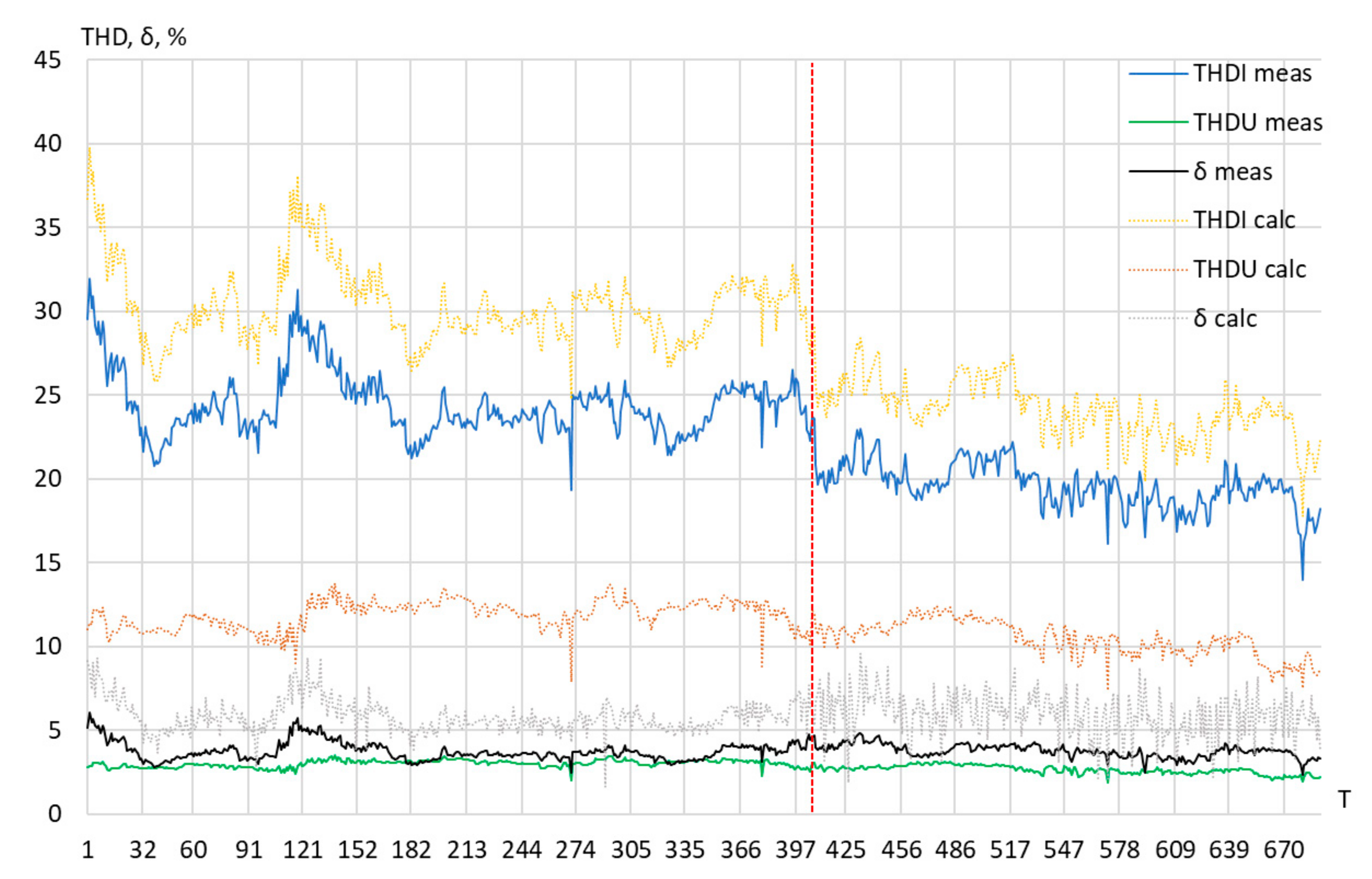
3.3. Reactive Power Measurement under Realistic Distortions

In order to assess the computational error of reactive power measurements according to Equations (3) and (7), field measurements of power consumption parameters and power quality indicators were carried out at the input feeder of an industrial enterprise. It is necessary to carry out measurements at an industrial facility because the phase shift angles of harmonics (ϕh) under such conditions can be very different from the angles in laboratory conditions. The measurements were carried out over 6 days (from 11 September 2020 to 14 September 2020 with the capacitor banks connected and from 14 September 2020 to 16 September 2020 with the capacitor banks disconnected), the maximum consumed active power was 230 kW, and reactive power was 310 kvar. The graph of the phase shift angle of harmonics for each 10-min time interval (T) is presented in Figure 6.
It can be seen from the graph that the phase shift angle of harmonics varies within wide limits, in particular, for the fifth harmonic, the phase shift angle varies from 0° to 70°. When capacitor banks are connected, the range of angle variation increases. It should be noted that the active power at the seventh harmonic is negative, which may indicate its occurrence from the grid side [26,27,28].
The following are field measurement results of THDU and THDI and the computational error of reactive power measurements according to various Equations (Figure 7), where the indicators with the “meas” index are measured data, and the indicators with the “calc” index are calculated data based on the measured ones. The calculated data were determined under the condition of an artificial increase in the amplitudes of the current and voltage harmonics, while the phase shift angles of harmonics were taken in accordance with the measured data in Figure 6.
It follows from the graph that for indicators with the “meas” index, the computational error of reactive power measurements according to various equations practically does not exceed 5%, while THDU varies from 2 to 3.5% and THDI varies from 14 to 33%. It should be noted that when capacitor banks are connected, THDI is slightly reduced, which may be a consequence of the total current compensation at the fundamental frequency, as well as the filtering properties of the capacitors. For indicators with a “calc” index, computational error of reactive power measurements according to various equations does not exceed 10% (on average it is about 7%), while THDU varies from 8 to 14%, THDI varies from 18 to 40%.
Thus, within the framework of the studies carried out, it can be concluded that the computational error of reactive power measurements according to various equations does not exceed 10%, provided that THDU does not exceed 14%, and THDI does not exceed 40%. These distortion values exceed the values specified in the power quality standards for low voltage. Therefore, if the voltage and current distortion values do not exceed the permissible values, then the reactive power calculation can be carried out at the fundamental frequency without significant computational errors.
As a result of the research performed, it is proposed to keep reactive power metering at the fundamental frequency, which results in minimization of a large number of factors affecting reactive power measurement, a decrease in the computational error (due to the use of various equations), as well as to a reduction in costs for the enhancement of metering devices (due to existing meters with computational equations for the fundamental frequency).

4. Conclusions

  • It has been revealed that, currently, virtually all enterprises can use electronic electricity meters, which give comparable readings for active and reactive energy in accordance with their accuracy class under sinusoidal conditions. Due to an increased distortion level in voltage and current, these energy meters are also used for measurements in the presence of harmonics. Under such conditions, the error of energy metering increases, wherein this error for active power depends on the number of harmonics taken into account and their amplitude, and for reactive power it depends further on the phase shift angle at the fundamental and high frequencies.
  • In the presence of distortion, different types of meters can give different readings, especially when measuring reactive power. The studies performed have shown that reactive power can be measured using various mathematical models. With sinusoidal voltage and current, this approach will give comparable readings with respect to power consumption; however, in the presence of harmonics, the readings can vary significantly. On the basis of field measurements, it was revealed that the variation range of the phase shift angles of harmonics significantly increases when capacitor banks are connected. It was also found that for the conditions under consideration, the computational error of reactive power measurements according to various equations does not exceed 10%, provided that the THDU does not exceed 14%, and the THDI does not exceed 40%. If the voltage and current distortion values do not exceed the permissible values, the error can be estimated at, at most, 5–7%.
Further research opportunities include the determination of phase shift angles of harmonics under conditions of various current and voltage distortions for a number of industrial enterprises with different nonlinear loads. On this basis, it is possible to determine a set of distortion ranges in which other patterns of power measurement will be observed.

Author Contributions

Conceptualization, Y.S.; methodology, Y.S. and A.S.; investigation, A.S.; writing—original draft preparation, Y.S.; supervision and project administration, Z.H. and Y.S.; writing—review and editing, Z.H. All authors have read and agreed to the published version of the manuscript.

Funding

This research received no external funding.

Conflicts of Interest

The authors declare no conflict of interest.

References

  1. Aryshnskii, E.V.; Bazhin, V.Y.; Kawalla, R. Strategy of refining the structure of aluminum-magnesium alloys by complex microalloying with transition elements during casting and subsequent thermomechanical processing. Non Ferr. Met. 2019, 46, 28–32. [Google Scholar] [CrossRef]
  2. Vasiliev, B.Y.; Kozyaruk, A.E.; Mardashov, D.V. Increasing the utilization factor of an autonomous inverter under space vector control. Russ. Electr. Eng. 2020, 91, 247–254. [Google Scholar] [CrossRef]
  3. Zhukovskiy, Y.; Koteleva, N. Development of augmented reality system for servicing electromechanical equipment. J. Phys. Conf. Ser. 2018, 1015, 042068. [Google Scholar] [CrossRef] [Green Version]
  4. Abramovich, B.N.; Veprikov, A.A.; Sychev, Y.A.; Lyakh, D.A. Use of active power transducers in industrial dc power systems supplying electrolysis cells. Tsvetnye Met. 2020, 2, 95–100. [Google Scholar] [CrossRef]
  5. ElDeeb, A.B.; Brichkin, V.N.; Bertau, M.; Savinova, Y.A.; Kurtenkov, R.V. Solid state and phase transformation mechanism of kaolin sintered with limestone for alumina extraction. Appl. Clay Sci. 2020, 196, 105771. [Google Scholar] [CrossRef]
  6. Sizyakov, V.M.; Vlasov, A.A.; Bazhin, V.Y. Strategy tasks of the Russian metallurgical complex. Tsvetnye Met. 2016, 1, 32–37. [Google Scholar] [CrossRef]
  7. Munoz-Guijosa, J.M.; Kryltcov, S.B.; Solovev, S.V. Application of an active rectifier used to mitigate currents distortion in 6–10 KV distribution grids. J. Min. Inst. 2019, 236, 229–238. [Google Scholar]
  8. Sychev, Y.; Abramovich, B.; Prokhorova, V. The assesement of the shunt active filter efficiency under varied power supply source and load parameters. Int. J. Electr. Comput. Eng. 2020, 10, 5621–5630. [Google Scholar] [CrossRef]
  9. Belsky, A.; Dobush, V.S.; Haikal, S.F. Operation of a single-phase autonomous inverter as a part of a low-power wind complex. J. Min. Inst. 2019, 239, 564–569. [Google Scholar] [CrossRef]
  10. Femine, A.; Gallo, D.; Landi, C.; Luiso, M. Advanced instrument for field calibration of electrical energy meters. IEEE Trans. Instrum. Meas. 2009, 58, 618–625. [Google Scholar] [CrossRef]
  11. IEC. Electricity Metering Equipment—Particular Requirements—Part 21: Static Meters for AC Active Energy (Classes 0,5, 1 and 2); IEC 62053-21:2020; IEC: Geneva, Switzerland, 2020. [Google Scholar]
  12. IEC. Electricity Metering Equipment—Particular Requirements—Part 22: Static Meters for AC Active Energy (Classes 0,1S, 0,2S and 0,5S); IEC 62053-22:2020; IEC: Geneva, Switzerland, 2020. [Google Scholar]
  13. IEC. Electricity Metering Equipment—Particular Requirements—Part 23: Static Meters for Reactive Energy (Classes 2 and 3); IEC 62053-23:2020; IEC: Geneva, Switzerland, 2020. [Google Scholar]
  14. IEC. Electricity Metering Equipment—Particular Requirements—Part 24: Static Meters for Fundamental Component Reactive Energy (Classes 0,5S, 1S, 1, 2 and 3); IEC 62053-24:2020; IEC: Geneva, Switzerland, 2020. [Google Scholar]
  15. Barbaro, P.V.; Cataliotti, A.; Cosentino, V.; Nuccio, S. A novel approach based on nonactive power for the identification of disturbing loads in power systems. IEEE Trans. Power Deliv. 2007, 22, 1782–1789. [Google Scholar] [CrossRef]
  16. Cataliotti, A.; Cosentino, V.; Salvatore, N. The measurement of reactive energy in polluted distribution power systems: An analysis of the performance of commercial static meters. IEEE Trans. Power Deliv. 2008, 23, 1296–1301. [Google Scholar] [CrossRef]
  17. Hu, W.; Duan, X.; Li, Q.; Zhang, L. Impact analysis and testing of harmonic of electrified railway on energy metering. Phys. Procedia 2012, 24, 1024–1030. [Google Scholar] [CrossRef] [Green Version]
  18. Driesen, J.; Van Craenenbroeck, T.; Van Dommelen, D. The registration of harmonic power by analog and digital power meters. IEEE Trans. Instrum. Meas. 1998, 47, 195–198. [Google Scholar] [CrossRef]
  19. Filipski, P.; Labaj, P.W. Evaluation of reactive power meters in the presence of high harmonic distortion. IEEE Trans. Power Deliv. 1992, 7, 1793–1799. [Google Scholar] [CrossRef]
  20. Ortiz, A.; Lehtonen, M.; Mañana, M.; Renedo, C.; Eguíluz, L.I. Energy meter behaviour under non-sinusoidal conditions. Renew. Energy Power Qual. J. 2004, 1, 296. [Google Scholar] [CrossRef]
  21. Bartolomei, L.; Cavaliere, D.; Mingotti, A.; Peretto, L.; Tinarelli, R. Testing of electrical energy meters subject to realistic distorted voltages and currents. Energies 2020, 13, 2023. [Google Scholar] [CrossRef] [Green Version]
  22. Ferrero, A. Definitions of electrical quantities commonly used in non-sinusoidal conditions. Eur. Trans. Electr. Power 2007, 8, 235–240. [Google Scholar] [CrossRef]
  23. Fiorucci, E. The measurement of actual apparent power and actual reactive power from the instantaneous power signals in single-phase and three-phase systems. Electr. Power Syst. Res. 2015, 121, 227–242. [Google Scholar] [CrossRef]
  24. IEEE Standard Definitions for the Measurement of Electric Power Quantities Under Sinusoidal, Nonsinusoidal, Balanced, or Unbalanced Conditions; IEEE 1459-2010; IEEE: New York, NY, USA, 2010.
  25. Gokhale, P.; Bakre, S. Impact of harmonics on accuracy of metering. In Proceedings of the International Conference on Information, Communication, Engineering and Technology (ICICET), Pune, India, 29–31 August 2018; pp. 1–3. [Google Scholar] [CrossRef]
  26. Hasanuzzaman Shawon, M.; Barczentewicz, S.; Bień, A.; Hanzelka, Z. Localization of Harmonic Sources in Power System—Simulation and Laboratory Study. Renew. Energy Power Qual. J. 2016, 1, 546–551. [Google Scholar] [CrossRef]
  27. Stevanovic, D.; Petkovic, P. A single-point method for identification sources of harmonic pollution applicable to standard power meters. Electr. Eng. 2019, 97, 165–174. [Google Scholar] [CrossRef]
  28. Lin, R.; Xu, L.; Zheng, X. A method for harmonic sources detection based on harmonic distortion power rate. IOP Conf. Ser. Mater. Sci. Eng. 2018, 322, 072038. [Google Scholar] [CrossRef] [Green Version]
Figure 1. Test bench.
Energies 13 05536 g001
Figure 2. Test bench for harmonic impact research on the metering error.
Energies 13 05536 g002
Figure 3. The dependences of the relative metering error for active and reactive power on the number of harmonics, where P1, Q1, P2, Q2—measured values by PM1 and PM2.
Energies 13 05536 g003
Figure 4. The dependences of the relative metering error for active power on the amplitude of the 5th harmonic current at different values of the phase shift angle at the fundamental frequency.
Energies 13 05536 g004
Figure 5. The dependences of the relative metering error for active and reactive power on the phase shift angle at the 5th harmonic.
Energies 13 05536 g005
Figure 6. The diagram of the phase shift angle at the 5th, 7th, and 11th harmonic (before red line—capacitor banks are connected; after red line—capacitor banks are disconnected).
Energies 13 05536 g006
Figure 7. The diagram of the total harmonic distortion—THDU and THDI—and computational error of reactive power measurements according to various equations.
Energies 13 05536 g007
Table 1. The equipment used in the laboratory bench.
Name of EquipmentTypeParameters
PQ analyzerResurs UF2Ma.c. 0.2/0.5 for P/Q, THDU range 0.5–30%
AC sourceEnergoforma 3.3relative error 2% at ULN1/I1 range 20–220 V/0.05–7 A
PM1Elster A1800a.c. 0.5 s/1.0 for P/Q, Un = 230 V, In(max) = 5(10) A
PM2PM710MGa.c. 1.0/2.0 for P/Q, Un = 230 V, In(max) = 5(6) A
Table 2. The program of experimental study.
ϕ1U5I5ϕ5U7I7ϕ7U11I11ϕ11U13I13ϕ13
1403040−100/17---------
2403040−100/172025−100/13------
3403040−100/172025−100/132117−95/10---
4403040−100/172025−100/132117−95/101815−95/10
5204060260/−50---------
6204060260/−502540260/−60------
7204060260/−502540260/−603025265/−70---
8204060260/−502540260/−603025265/−702520265/−70
915/4015250---------
1015/40152530---------
1115/40152560---------
1215/40152590---------
1315/401525120---------
1415/401525150---------
1515/401525180---------
1615/4015150---------
1715/4015300---------
1815/4015450---------
1915/4015600---------
Table 3. The equipment used in the laboratory bench.
EquipmentTypeParameters
LTSuntekSn = 20 kVA, Un = 220/380 V, Imax = 80 A
AMAIR 80 APn = 1.5 kW, Un = 220/380 V, cosφ = 0.84
CBCB-134-0.4-3-0.5Qn = 2.5 kvar, Un = 220/380 V, ftun = 134 Hz
URDiode RectifierPn = 1.0 kW, Un = 220/380 V, Imax = 60 A, m = 6
PM3A43 412-200a.c. 1.0/2.0 for P/Q, Un = 3x230/400 V, In(max) = 5(80) A
PM4230 ARa.c. 1.0/2.0 for P/Q, Un = 3x230/400 V, In(max) = 5(60) A
Table 4. The modes of laboratory installation.
Mode NumberAM with DC GeneratorCBUR with HRPower Factor
Mode 1+-+0.42 (+L)
Mode 2+++0.94 (+L)
Mode 3+++0.92 (−C)
Mode 4+-+0.74 (+L)
Mode 5+++0.94 (+L)
Mode 6+++0.88 (−C)
Table 5. Power consumption parameters at the test bench.
NPM3PM4PQ AnalyserPower
Factor
δQ1, %δQ2, %
P, WQ, varP, WQ, varP, WQ, var
17281554733156972915500.42 (+L)0.31.2
27721837712607732400.94 (+L)−23.88.3
3785−285787−322787−3400.92 (−C)−16.2−5.3
41408129314041332140913300.74 (+L)−2.80.2
51420480142052214215000.94 (+L)−4.04.4
61442−7761441−7801444−7900.88 (−C)−1.8−1.3
Publisher’s Note: MDPI stays neutral with regard to jurisdictional claims in published maps and institutional affiliations.

