Abstract
Thermal hydraulic performance of the fin-and-tube heat exchanger is presented in this paper. The purpose of this investigation was to investigate the heat transfer mechanism and flow characteristics in the finned tube heat exchanger with streamline tube. The streamline tube in this paper had the streamline cross section which was composed of a semicircle and a half diamond. Three-dimensional numerical simulation was presented and validated by the experiment and the other numerical simulation from public articles. The present simulation had good agreement with the experimental results. The difference of the j factor and f factor between the experimental results and present simulation results by k-ε-enhance model was less than 7.6%. The geometrical parameters were considered as every single variable to investigate the thermal hydraulic performance. The results showed that smaller transversal and larger tube pitch provided greater compactness and better thermal performance. Moreover, a larger angle was not only beneficial to enhance the thermal performance, but also helpful to improve the overall performance. Secondly, the effects of angle on the heat transfer performance and fluid flow characteristics were investigated as the perimeter kept constant. It was shown that the overall performance of the streamline tube was better than the circular tube. Lastly, the entropy generation including frictional entropy generation and the thermal entropy generation were analyzed. It can be concluded that by using the streamline tube, the wake region can be obviously reduced, and thermal performance can be improved.
Highlights
- Flow characteristics in the windward region and wake region flow characteristics were investigated.
- By decreasing wake region, the flow characteristic was improved and the overall performance was enhanced.
- The k-ε-enhance model was employed to numerically investigate the overall performance.
1. Introduction
Due to the high effective thermal performance and compact structure, fin-and-tube heat exchangers were widely used in various fields, mainly in air-conditioning and refrigeration system, petrochemical industry, electronics cooling, thermoelectric sensors and so on. As known, the thermal resistance in the shell side was almost up to 90% [1]. Thus, it was crucial to reduce the thermal resistance in the shell side. In many articles, kinds of geometrical configurations were analyzed to enhance the heat transfer performance, increasing the flow resistance. However, the elliptical tube had better aerodynamic shape than the circular one, and the total drag forces of the elliptical tube were much smaller than the circular one. Nowadays, fin-and-elliptical tube heat exchangers are adopted to reduce the pressure drop and the weak region of the fins behind the tube. Substantial experiments [2] and numerical simulations [3,4,5,6] focused on fin-and-elliptical tube heat exchangers for energy conversion and utilization. Compared with the fin-and-circular tube heat exchangers, the fin-and-elliptical tube heat exchangers had small pressure drop and worse heat transfer performance [7,8].
As known, the laminar flow near the wall blocked the heat transfer due to the viscosity of the working fluid. Moreover, the turbulence flow was beneficial to improve heat transfer performance. Thus, some fins, including shaped fin [9], vortex generators [10], slit fin [11], louver fin [12], were adopted to enhance the thermal performance by increasing turbulence intensity. However, fluid flow characteristics became worse due to those internal insert parts, even though some researchers had focused on the combination of these internal insert parts. Babak Lotfi [13] proposed a smooth wavy fin-and-elliptical tube heat exchanger to research the three new types of vortex generators. R. Deepakkumar [14] had combined the circular tubes and the elliptical tubes and conducted a three-dimensional numerical investigation to research the heat exchanger performance. They both found that by using combination of these internal insert parts, the heat transfer performance had been obviously improved.
Though the internal insert parts in the heat exchanger increased the heat transfer performance, large cost of energy was inevitable. The elliptical tube had been adopted in the fin-and-tube heat exchangers and was beneficial for improving the fluid flow characteristics. Due to the structure of elliptical tube, less turbulence was produced, and a better comprehensive performance was obtained. Hui Han [15] numerically investigated the fluid flow and heat transfer characteristics of finned tube heat exchangers with oval and circular tubes, and the results revealed that using the oval fin-and-tube heat exchanger can not only reduce the flow resistance but also improve the heat transfer capacity of the heat exchangers that effectively improved the fin efficiency. In addition, Lei Sun [16] had proposed a numerical model and found the overall thermal–hydraulic performance, which was quantified by the heat transfer rate per unit power consumption, was better in the elliptical finned-tube heat exchanger. Furthermore, Siavash Vaezi [17] carried out a numerical study for alternating oval double pipes to analyze the suggested configurations under different conditions and concluded that heat transfer rate of alternating oval double pipes had higher values than the circular type, and the pressure loss effects were revealed to be dominant over the heat transfer improvement. J.V. Simo Tala [18] presented unsteady-RANS simulations to investigate the effect of the iso-sectional tube shape modification on the air-side thermal hydraulic characteristics. Obviously, in these studies, the elliptical finned-tube heat exchanger had a better flow characteristic.
To provide better sustainability of enhancement of heat transfer performance, entropy generation analysis was adopted. As known, the entropy generation was related to the geometrical parameters and the thermophysical properties of the working fluid. The entropy generation reflected the exergy loss. Entropy generation analysis on the fluid flow and heat transfer were published in some public articles [19,20]. Amin Ebrahimi [21] numerically investigated conjugated heat transfer and hydraulic performance for nanofluid flow in a rectangular microchannel heat sink with longitudinal vortex generators. Entropy generation was analyzed and the results showed that using nanofluids as working fluid can reduce the irreversibility level. Eyuphan Manay [22] researched the effects of presence of nanosized TiO2 particles in the base fluid on entropy generation rate in a microchannel heat sink. It can be observed that frictional and total entropy generation rate increased as thermal entropy generation rate decreased with an increase in particle volume fraction. J.A. Esfahani [23] analyzed the entropy generation for the Cu-water nanofluid flow through a wavy channel over a heat exchanger plate. The obtained results indicated that the thermal entropy generation was the main term in most parts of the channel. M. Akbarzadeh [24] performed a numerical simulation on entropy generation and thermo-hydraulic performance of a wavy channel with three corrugation profiles. It was found that among wavy channels, the triangular channel provided the highest thermal entropy generation, followed by the sinusoidal and trapezoidal channels. However, most entropy generation analyses in those articles focused on 2D computational models or empirical formulas.
Much research focused on the effect of different geometrical parameters on the thermal hydraulic performance but did not elaborate on the reason to enhance the heat transfer performance and improve the flow resistance characteristics. Clearly, it is crucial to acquire a better understanding of thermal mechanism in the fin-and-tube heat exchanger. Furthermore, most articles investigated the entropy generation on the two-dimensional model. In this paper, the thermal mechanism is revealed and entropy generation on the three-dimensional model is studied. A streamline cross section that was composed of a semicircle and a half diamond was adopted. This paper aimed to investigate the thermal hydraulic performance of the streamline tube in the heat exchangers.
2. Model Description
2.1. Physical Model
The research object in the paper was a four-row staggered fin-tube heat exchanger. Figure 1 showed the definition of the circular tube and streamline tube geometrical parameters in the heat exchanger. The circular heat tube was shown in Figure 1a, and the streamline tube was shown in Figure 1b, which was composed of half circle and half diamond. The parameters of circular tube and streamline tube fin-tube heat exchanger are shown in Table 1. The geometrical parameters of all the cases are shown in the Table 2. The geometry parameters used in this study are adopted based on the previous article [25]. The perimeter of the heat tube section was considered in the paper, defined as follow:
where R is the radius of the heat transfer tube section, shown in Figure 1. R was the main geometry parameter, and r is chamfer size, which can be neglected. In this paper, r is set as 0.1 mm, and . is the angle of heat transfer tube section.
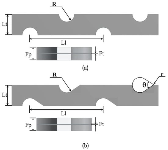
Figure 1.
Definitions of geometrical parameters of the circular tube and streamline tube plate fin-tube heat exchanger: (a) circular tube plate fin-tube heat exchanger; (b) streamline tube plate fin-tube heat exchanger

Table 1.
The parameters of circular tube and streamline tube fin-tube heat exchanger.
Table 2.
The geometrical parameters of all the cases.
In this model, the material of the heat exchanger was aluminum, of which the physical properties were given as: , , . The material of the working fluid was air, of which the physical properties were given as: , , , . In order to pursue an efficient calculation, the computational model considered was a periodic model, seen as in Figure 2. Figure 2 shows the detailed boundary conditions of the computational domain.
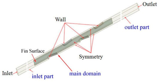
Figure 2.
The schedule of boundary conditions on the plate fin-and-tube heat exchanger.
2.2. Governing Equations
Some simplified assumptions were required before applying the conventional flow equations and energy equations to model the heat transfer process in the tube-and-fin heat exchanger.
It was assumed as follows [26]:
- (1)
- A steady state was assumed;
- (2)
- The flow was three-dimensional and incompressible;
- (3)
- The working fluid was in a single phase, and their properties kept constant;
- (4)
- Effects of heat dissipation and thermal radiation were negligible;
The air flow was turbulent and steady. The equations governing the air flow and heat transfer can be expressed as follows.
Continuity equation:
Momentum equation:
Energy equation:
where the Reynolds stresses were
The present research adopted the k-ε-enhance model. k is the turbulent kinetic energy, and ε is the turbulent dissipation energy.
Turbulent kinetic energy:
Turbulent dissipation energy:
The values for constants and the expressions for variables can be found in the Fluent handbook [3,27]. For flow in the near wall region, the near wall treatment is needed. The first near wall grid is placed at less than unity so that the enhanced wall function can be employed [28].
2.3. Boundary Conditions
In order to reduce the effect of turbulence on the simulation, the turbulence intensity was considered in the inlet part and outlet part, defined as follows [27,29].
In this paper, the corresponding turbulence intensity in the inlet part and outlet part were fixed at 6.53%, 6.43%, 6.33%, 6.26%, and 6.19%, respectively.
Figure 2 shows the schedule of boundary conditions on the finned streamline tube heat exchanger. The Reynolds numbers based on hydraulic diameter and inlet velocity were 1300, 1475, 1650, 1825, and 2000. A series of uniform velocities were set at the inlet part, revealed as Equation (9). The velocity values were 3.16 m/s, 3.59 m/s, 4.02 m/s, 4.44 m/s, and 4.87 m/s, respectively. The temperature in the inlet was set as . The side boundary condition and periodic conditions were adopted in this paper. Generally, the computational domain was divided into three parts, including inlet part, outlet part, and fin-coil part (main domain), as seen in Figure 2. The boundary conditions of inlet part, outlet part, and fin-coil part were described as follows.
- (1)
- Boundary conditions of inlet part were described as follows [4].At inlet boundary condition:At side boundary conditions:At the top and bottom boundaries (periodic conditions):
- (2)
- The boundary conditions of outlet part were described as follows.At outlet boundary condition:At side boundary conditions:At the top and bottom boundaries (periodic conditions):
- (3)
- The boundary conditions of Fin-coil part are described as follows.At side boundary condition:At the top and bottom boundaries (periodic conditions):
3. Model Verification
3.1. Parameter Definition
In order to judge the thermal performance and flow resistance, two factors were adopted in this paper, namely j factor and f factor. The overall performance JF factor was adopted to judge the comprehensive performance of the heat exchanger. Before introducing these three factors, some basic parameters should be presented.
Diameter-based Reynolds number, Nusselt number, and Prandtl number were defined as follows.
Among these non-dimensional parameters, the hydraulic diameter and kinematic viscosity were defined, respectively, as follows.
The air-side heat transfer coefficient was defined as follows:
The total rate of heat transfer used in the calculation was defined as follows.
Moreover, the log-mean temperature difference was defined as follows [30,31]:
In this paper, f factor and j factor are adopted to judge the flow characteristic resistances and the heat transfer performance.
- (1)
- Friction factor f represented the friction characteristic, defined as follows.
- (2)
- Colburn factor j represented the heat transfer capability, defined as follows.
- (3)
- In order to evaluate the overall performance of the tube-and-fin heat exchanger, the performance evaluation is used to evaluate the thermal performance, suggested by Webb [32], defined in terms of Colburn factor and Friction factor as follows.
3.2. Entropy Generation Analysis
The entropy generation was due to heat transfer over a finite temperature difference and viscous dissipation [33,34]. The three-dimensional local volumetric entropy generations rates, accounting for thermal and friction effects in Cartesian coordinates, were respectively defined as follows [24].
where and are the local entropy generation rates due to heat transfer irreversibility and fluid friction irreversibility, respectively. is the local volumetric entropy generations rate.
Furthermore, to assess the contribution of heat transfer and fluid friction in total irreversibility, a non-dimensional parameter, Bejan number (Be), can be expressed as follows [22,24].
3.3. Mesh Generation Technique
The whole geometry of the heat exchanger was symmetrical and periodical, which was modeled by Design Modeler Ansys 13.0. The computational domain was part of the exchanger with simplification. The structured hexahedral mesh was generated, and the governing equations along with the boundary condition equations were solved by ANSYS FLUENT 13.0. The convective terms in the governing equations for momentum and energy were discretized with the second-order upwind scheme. The coupling between velocity and pressure was performed with the SIMPLE algorithm. To ensure the computational convergence, the under-relaxation factors were 0.3, 0.7, and 0.8 for the pressure, momentum, and energy, respectively. The typical CPU time for each case was about 2 h.
Larger numbers of grids would occupy larger CPU resources which means more time for calculation. Meanwhile, smaller numbers of grid would lead to larger difference between numerical and the experimental results. Thus, a reasonable grid number was necessary to guarantee CPU operation speed and acceptable difference. In this paper, four different numbers of grids, including 490,628, 840,365, 1,584,653, and 2,794,732 elements, were considered to evaluate, as seen in Figure 3. The results showed that the average j factor and f factor of the 1,584,653 mesh elements varied from that of the 2,794,732 mesh elements by less than 2% and 1.08%, respectively. Therefore, the mesh with 1,584,653 grid elements was adopted to conduct the numerical simulation. Moreover, the grid independence of the other cases was also tested.
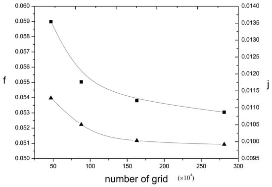
Figure 3.
The grid independence with Re = 2000.
3.4. Code Validation
The present simulation results were validated by Wang’s experiment [35] and Arafat’s simulation [25], as shown in Figure 4, which revealed the comparison of numerical and experimental f factor and j factor for the plate fin-tube heat exchanger. The boundary conditions of Wang’s experiment and Arafat’s simulation were presented as the same as in this paper. The simulation was conducted by k-ε-enhance, and the k-ε-enhance had a good agreement with the experimental results of the f factor. Moreover, the resistance between fluid and solid was considered, and the thermal resistance value was set as . The procedure had been discussed in detail in the published article [36]. Some reasons accounted for the difference between the experiment and the simulation: the working fluid was in a single phase, and their properties remained constant and smooth surface conditions were adopted in the simulation. Additionally, the difference of the j factor and f factor between the Arafat’s simulation [25] and the present numerical results was less than 3.82% and 4.90%, respectively. The difference of the j factor and f factor between the experimental results and present simulation results by k-ε-enhance model was less than 7.6%. It can be observed that the present simulation had good agreement with Arafat’s simulation [25] and Wang’s experimental results [35].
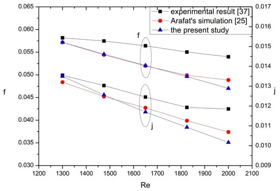
Figure 4.
Comparison of numerically and experimentally obtained f factor and j factor for the plate fin-tube heat exchanger.
4. Results and Discussion
As known, the elliptical tube had better comprehensive performance and worse thermal performance. In this paper, the streamline tube was researched to explore the heat transfer mechanism and fluid flow characteristics. As mentioned before, the 3D computational model was validated by the experimental results from Wang [35] and the numerical results from Arafat [25]. Eighteen cases of streamline tube were numerically investigated, as seen in Table 1. The discussed Reynolds numbers were from 1300 to 2000 in this paper.
4.1. Discussion of the Effect of Geometrical Parameters
In this section, three parameters, including transversal tube pitch Lt, longitudinal tube pitch Ll and angle , were respectively considered as single variables to research the effect on the thermal hydraulic performance. The discussed ranges of these geometrical parameters were 15.4–23.4 mm (transversal tube pitch), 16–24 mm (longitudinal tube pitch), and 40–80° (angle), respectively.
4.1.1. The Effect of Transversal Tube Pitch
Five different transversal tube pitches were displayed. The transversal tube pitches of Case 2, Case 3, Case 4, Case 1, and Case 5 were 15.4 mm, 17.4 mm, 19.4 mm, 21.4 mm, and 23.4 mm, respectively. Among these cases, Case 1 was considered as baseline.
As seen in Figure 5a,b, with the increase of the transversal tube pitch, the j factor was increased. Case 2, Case 3, and Case 4 had a 13.89%, 11.1%, and 4.45% higher j factor and 55.45%, 25.61%, and 11.99% higher f factor, when compared with the Case 1, respectively. Besides, compared with Case 1, Case 5 had a 0.26% lower j factor and 9.64% lower f factor. Clearly, the transversal tube pitch had great influence on the f factor than the j factor. Yet, as seen in the Figure 5c, the increase rate of the JF factor was less than 4%. Compared with Case 1, Case 2 had a 1.67% lower JF factor. Case 3, Case 4, and Case 5 had a 2.97%, 0.58%, and 3.17% higher JF factor than Case 1, respectively. Figure 5d revealed the flow field of different transversal tube pitches.
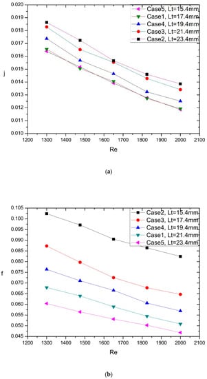
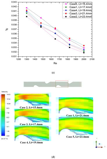
Figure 5.
(a) j factor of different transversal tube pitches on Reynolds number, (b) f factor of different transversal tube pitch on Reynolds number, (c) JF factor of different transversal tube pitch on Reynolds number, (d) The flow field of different transversal tube pitch.
Obviously, smaller transversal tube pitch provided greater compactness and better thermal performance at the cost of worse flow characteristics, but the overall performance was not evidently improved.
4.1.2. The Effect of Longitudinal Tube Pitch
In order to investigate the effect of longitudinal tube pitch on the thermal hydraulic performance, five cases with different longitudinal tube pitches were investigated. The longitudinal tube pitches of Case 6, Case 7, Case 1, Case 8, Case 9 were 16 mm, 18 mm, 20 mm, 22 mm, and 24 mm, respectively. Case 1 was considered as baseline.
As revealed in Figure 6a, Case 6 and Case 7 had 33.28% and 18% higher j factor than Case 1, respectively, while the f factor of Case 6 and Case 7 was 6.14% and 6.25% higher, as seen in the Figure 6b, resulting in the JF factor of Case 6 and Case 7 being 30.68% and 15.67% higher than Case 1, as shown in the Figure 6c. In addition, Case 8 and Case 9 had a 0.44% and 2.87% lower f factor than Case 1. However, Case 8 had almost the same j factor and Case 9 had 2.42% lower j factor when compared with Case 1. As a result, the JF factor of Case 8 and Case 9 were both almost the same as that of Case 1. As seen in the Figure 6c, Case 8 and Case 9 had 0.35% higher and 1.47% lower JF factor than Case 1. Figure 6d showed the flow field of different longitudinal tube pitches.
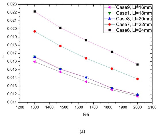
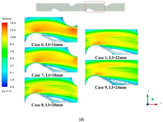
Figure 6.
(a) j factor of different longitudinal tube pitch on Reynolds number, (b) f factor of different longitudinal tube pitch on Reynolds number, (c) JF factor of different longitudinal tube pitch on Reynolds number, (d) The flow field of different longitudinal tube pitch.
Smaller longitudinal tube pitch was beneficial for the improvement of thermal performance and comprehensive performance. The configuration of the streamline heat tube was beneficial to reduce the influence of Karman Vortex Street behind the tube. Compared with circular tube, the streamline tube had smaller wake region which was harmful to the heat transfer and fluid flow. Therefore, appropriate longitudinal tube pitch was helpful for the enhancement of the heat transfer performance and the improvement of the comprehensive performance.
4.1.3. The Effect of Angle
Similarly, five cases with different angles were researched to discuss the influence of the angle on the thermal hydraulic performance. The discussed angles were in the range of and . The angles of Case 10, Case 11, Case 1, Case 12, Case 13 were , , , , , respectively. Still, Case 1 was considered as baseline.
As seen in Figure 7a–c, Case 10 and Case 11 had 5.92% and 4.77% lower f factor and 5.08% and 3.17% higher j factor, which led to 7.24% and 4.87% higher JF factor when compared with Case 1, respectively. Besides, Case 12 and Case 13 had 2.1% and 3.75% higher f factor than Case 1, but the j factor of Case 12 and Case 13 was a little lower than that of the Case 1. Eventually, the JF factor of Case 12 and Case 13 was 0.01% and 1.01% lower JF factor than that of Case 1. The flow field of different angle as the radius remained constant can be observed in Figure 7d.
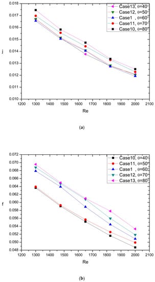
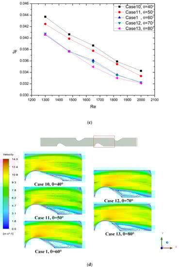
Figure 7.
(a) j factor of different angle on Reynolds number, (b) f factor of different angle on Reynolds number, (c) JF factor of different angle on Reynolds number, (d) The flow field of different angles as the radius keep constant.
When the angle became smaller, the heat exchange area was increased with the increasing of the tube cross section perimeter. Besides, the wake region became smaller as the angle increased and it was beneficial for the enhancement of heat transfer performance and improvement of fluid flow characteristics. Obviously, decreasing the angle was not only beneficial to enhance the thermal performance, but also helpful to improve the flow characteristics.
In the previous analysis, the tube radius R remained constant. Under this condition, the heat exchange area, which had great influence on the thermal hydraulic performance, was variable versus angle. The following analysis on the angle would be investigated under the condition that the tube section perimeter kept constant. As a consequence, the heat exchange area between hot fluid and cold fluid could also keep constant.
4.2. Analysis on the Thermal Hydraulic Performance
Five cases with the perimeter kept constant were investigated in this section. In order to keep the perimeter constant, the diameter varied with the angle. The angles were in the range between and .
4.2.1. Analysis on the Flow Characteristics and Thermal Performance
Figure 8a shows the effect of different angle on the j factor at different Reynolds numbers. It can be observed that the j factor of the circular tube was higher than that of the streamline tube. As mentioned above, the perimeter of the tube section remained constant, and in order to keep it constant, the windward area of the streamline tube was smaller than the circular tube when the angle was between and . As known, the windward area was the main heat transfer region. As the angle decreased, the windward area of the streamline tube was also decreased which caused that the heat transfer performance of the circular tube was better than the streamline tube.
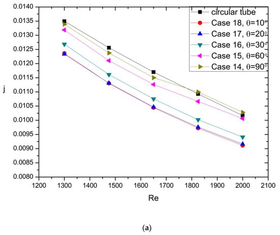
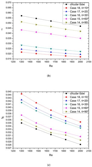
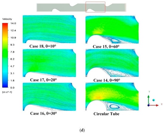
Figure 8.
(a) Effect of different angle on the j factor at different Reynolds numbers, (b) Effect of different angle on the f factor at different Reynolds numbers, (c) Effect of different angle on the JF factor at different Reynolds numbers, (d) The flow field of different angle as the perimeter keep constant.
As shown in Figure 8a, Case 14 had 1.8% lower j factor than the circular tube. Due to the little difference of dimension, the difference of j factor between the circular tube and the Case 14 was small. Case 15, Case 16, Case 17, and Case 18 had 3.94%, 8.72%, 11.14%, and 11.30% lower j factor than the circular tube. It can be observed that the j factor decreased as the angle decreased. When the angles were between and , the j factor decreased rapidly, but when the angle was less than , the j factor drop was negligible.
With the decrease of the streamline tube angle , the flow characteristics were much better than the circular tube. In Figure 8b, it can be seen that Case 14 had 11.48% lower f factor than the circular tube. Though the dimension difference between the circular tube and the streamline tube was small, the flow resistance of the streamline tube was much lower than that of the circular tube. In addition, the Case 15, Case 16, Case 17, and Case 18 had 25.25%, 52.13%, 58.45%, and 63.44% lower f factor than the circular tube, respectively. It can be observed that the f factor was obviously decreased as the angle decreased.
Compared the j factor and the f factor in the Figure 8a,b, the improvement of the flow characteristics was much remarkable than the loss of heat transfer rate. As mentioned before, the section of streamline tube can improve the flow characteristics. Moreover, the flow resistance became smaller because the channel between the tubes became smaller as the angle decreased.
The JF factor was adopted to judge the thermal hydraulic comprehensive performance. As the angle decreased from 90° to 60°, the comprehensive performance of the streamline tube was much better than the circular tube. The effect of different angles on the JF factor at different Reynolds numbers is shown in Figure 8c. It can be revealed that streamline tube had higher JF factor than the circular tube. Case 14, Case 15, Case 16, Case 17, and Case 18 had a 3.29%, 6.55%, 15.22%, 16.93%, and 20.25% higher JF factor than the circular tube, respectively. As the angle was between 20° and 60°, the JF factor obviously increased with the decrease of angle, as seen in the Figure 8c. Figure 8d presented the flow field of different angle as the perimeter remained constant.
In this section, the perimeter was kept constant to ensure the heat exchange area was constant. Under this condition, the radius decreased as the angle decreased. Moreover, with the deceasing of angle, heat transfer performance was decreased, and the flow characteristics were enhanced, eventually, improving the comprehensive performance.
4.2.2. Analysis on Turbulence Kinetic Energy
Due to the better aerodynamic shape, the streamline tube had less turbulence than the circular tube, as seen in Figure 9. Figure 9 revealed the turbulence kinetic energy distribution of the circular tube and streamline tube. It can be seen that the circular tube had larger turbulence kinetic energy than the streamline tube, especially in the channel between the tubes. Besides, with the decrease of the angle θ, the turbulence was obviously decreased, and the wake region was decreased. When the tube fin heat exchanger adopted the streamline tube, the windward area and the weak region were both smaller than that of the circular tube, which can effectively reduce the flow resistance. As the windward face decreased, turbulence decreased, resulting in a worse heat transfer performance and a better comprehensive performance, seen in Figure 8a,c. Hence, when the perimeter remained constant, the streamline tube can effectively reduce flow resistance and improve the comprehensive performance.
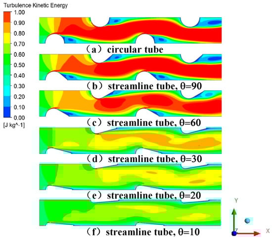
Figure 9.
Turbulence kinetic energy distribution of the circular tube and streamline tube.
4.2.3. Analysis on the Entropy Generation
The entropy generation consists of two parts, including thermal effect and friction effect. In this paper, the thermal entropy generation Sght was defined as Equation (31), and the frictional entropy generation Sgff was defined as Equation (30). The Local Sgff distribution around the tube at different angles was shown in Figure 10. As the second law of thermodynamics states, the total entropy always increases, and the process is irreversible. The frictional entropy generation reflected irreversibility degree of the conversion of kinetic energy into thermal energy. Therefore, the frictional entropy generation can be used to reflect the energy loss. As it can be observed in Figure 10, the frictional entropy generation was mainly focused on the first half of the tube and extended behind the tube. The irreversibility degree of the frictional entropy generation became smaller as the angle decreased. In addition, Figure 11 showed the effect of different angle on Sgff at different Reynolds numbers. It can be seen in Figure 11 that Case 14, Case 15, and Case 16 had 4.31%, 8.90%, and 19.91% lower Sgff than the circular tube, respectively. Besides, The Case 17 and Case 18 had been 22.92% and 24.64% lower Sgff than the circular tube, respectively. Evidently, the streamline tube had better flow resistance than the circular tube, and with the decrease of angle, the frictional entropy generation gradually decreased.
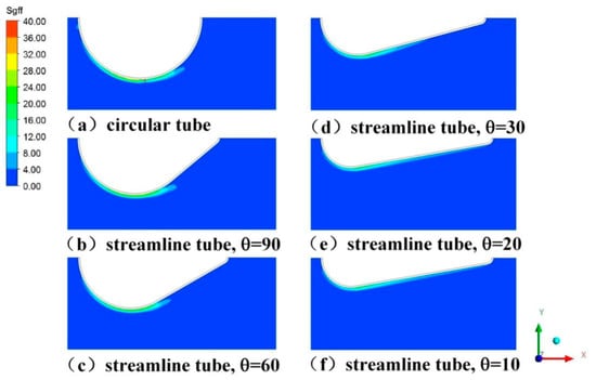
Figure 10.
Local Sgff distribution around the tube at different angle.
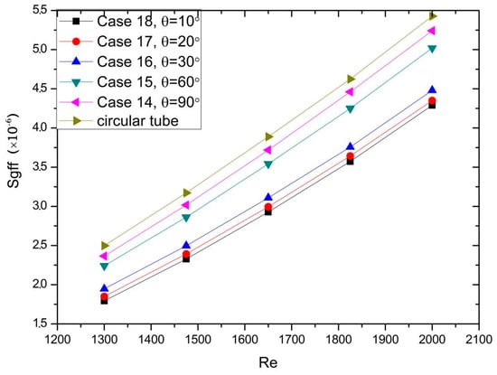
Figure 11.
Effect of different angle on Sgff at different Reynolds numbers.
The thermal entropy generation is an index to reflect the irreversibility of heat transfer from high temperature object to low temperature object. Actually, in the heat exchanger, the heat is transferred from high temperature object to low temperature object, and this endeavor was done to enhance the heat transfer efficiency. Thus, greater thermal entropy generation indicates better heat transfer performance [37]. As it can be seen in Figure 12, the main thermal entropy generation was concentrated around the tube. The thermal entropy generation of the circular tube was mainly focused on the first half of the tube, while in the second half of streamline tube, the thermal entropy generation gradually increased with the decrease of angle. Figure 13 showed the effect of different angle on Sght at different Reynolds numbers. It can be seen in Figure 13 that Case 14, Case 15, and Case 16 had 2.75%, 6.21%, and 18.31% higher Sght than the circular tube, respectively. Besides, Case 17 and Case 18 were 23.57% and 32.40% higher Sght than the circular tube, respectively. It can be observed that the streamline tube had higher thermal entropy generation than the circular tube, and with the decrease of angle, the thermal entropy generation was gradually increased.
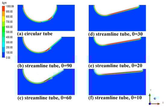
Figure 12.
Local Sght distribution around the tube at different angle.
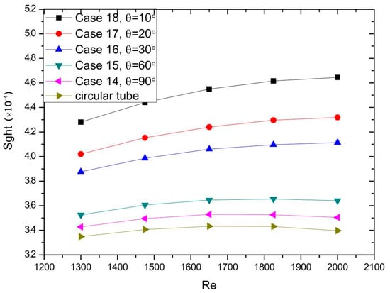
Figure 13.
Effect of different angle on Sght at different Reynolds numbers.
In order to quantize the contribution of each term in the total irreversibility, the Bejan number was considered. Figure 14 showed the effect of different angle on Be at different Reynolds numbers. It can be found that the contribution of the thermal entropy generation was much higher than that of the frictional entropy generation. Besides, with the decrease of the angle, the frictional entropy generation decreased, and the thermal entropy generation increased. Thus, the total entropy generation was more affected by the latter, resulting in a higher Bejan number, as seen in the Figure 14.
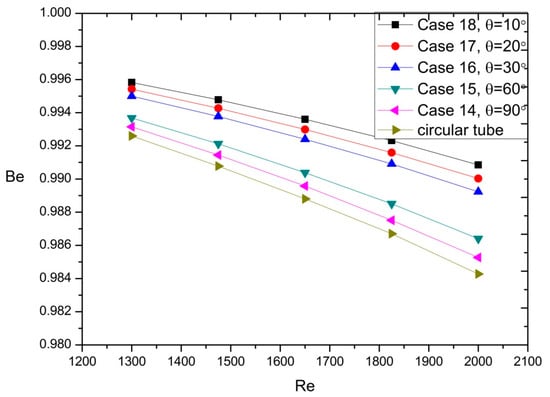
Figure 14.
Effect of different angle on Be at different Reynolds numbers.
5. Conclusions
The streamline tube was investigated to discuss the effect of streamline tube on the thermal hydraulic behavior of fin-and-tube heat exchangers by numerical simulations. 3D computational models were validated by experimental results from Wang and the numerical data from Arafat. Some conclusions can be obtained.
Based on the simulation, it was found that transversal tube pitch, longitudinal tube pitch, and angle had great influence on the thermal hydraulic performance. When the radius R remained constant, both small transversal tube pitch and small longitudinal tube pitch can improve the heat transfer performance and generate large flow resistance. However, increasing the angle was not only beneficial to enhance the thermal performance but also helpful to improve the flow characteristics. In addition, compared with circular tube, the streamline tube had a smaller wake region. Streamline tube in the fin-and-tube heat exchanger was helpful for the enhancement of the heat transfer performance and the improvement of the comprehensive performance.
As the perimeter of tube cross section remained constant, the heat exchange area between hot fluid and cold fluid also kept constant. When the angle decreased, the windward area and wake region were both decreased, leading to a lower f factor and j factor. However, the drop of the f factor was larger than that of the j factor, which resulting in a better comprehensive performance as the streamline angle decreased.
An analysis of the entropy generation was conducted in this paper. As the streamline angle decreased, the frictional entropy generation decreased, but the thermal entropy generation increased. It can be found that the contribution of the thermal entropy generation was much higher than that of the frictional entropy generation. Thus, the total entropy generation was more affected by the thermal entropy generation which had a positive effect on the Bejan number.
Author Contributions
Conceptualization, Q.W. and Z.Q.; methodology, Q.W.; software, Q.W.; validation, Q.W., Z.Q. and S.L.; formal analysis, Q.W.; investigation, Q.W.; resources, Q.W.; data curation, S.L.; writing—original draft preparation, Q.W.; writing—review and editing, Q.W.; visualization, S.L.; supervision, Z.Q.; project administration, Z.Q.; funding acquisition, Z.Q. All authors have read and agreed to the published version of the manuscript.
Funding
This research received no external funding.
Conflicts of Interest
The authors declare no conflict of interest.
Nomenclature
| The total area of heat transfer () | |
| The wetted surface area () | |
| The Bejan number () | |
| () | |
| The heat capacity of working fluid () | |
| The perimeter of the heat transfer section () | |
| The hydraulic diameter () | |
| Fin pitch () | |
| Fin thickness () | |
| The friction factor ( | |
| () | |
| The turbulence intensity () | |
| The Colburn factor () | |
| k | Turbulent kinetic energy () |
| () | |
| The length of flow direction () | |
| Longitudinal tube pitch () | |
| Transverse tube pitch () | |
| The mass flow of working fluid () | |
| The Nusselt number () | |
| P | () |
| () | |
| The total rate of heat transfer () | |
| The Reynolds number () | |
| The large radius of the heat transfer tube () | |
| The small radius of the heat transfer tube () | |
| The local thermal entropy generation rate | |
| The local frictional entropy generation rate | |
| The local volumetric entropy generations rate | |
| The temperature of the outlet () | |
| The temperature of the inlet () | |
| The temperature of wall () | |
| Temperature of the working fluid () | |
| u | () |
| () | |
| Volume of working fluid () | |
Greek Symbols
| The pressure drop between the inlet and outlet () | |
| () | |
| Dissipation rate of turbulent kinetic energy of the k- model () | |
| () | |
| () | |
| Dynamic viscosity () | |
| () | |
| Kinematic viscosity () | |
| Density of working fluid () | |
| () | |
| () | |
| The streamline () |
Subscripts
References
- He, Y.L.; Chu, P.; Tao, W.Q.; Zhang, Y.W.; Xie, T. Analysis of heat transfer and pressure drop for fin-and-tube heat exchangers with rectangular winget-type vortex generators. Appl. Therm. Eng. 2013, 61, 770–783. [Google Scholar] [CrossRef]
- Du, X.; Zeng, M.; Dong, Z.; Wang, Q. Experimental study of the effect of air inlet angle on the air-side performance for cross-flow finned oval-tube heat exchangers. Exp. Therm. Fluid Sci. 2014, 52, 146–155. [Google Scholar] [CrossRef]
- Gu, L.; Min, J.; Wu, X.; Yang, L. Airside heat transfer and pressure loss characteristics of bare and finned tube heat exchangers used for aero engine cooling considering variable air properties. Int. J. Heat Mass Transf. 2017, 108, 1839–1849. [Google Scholar] [CrossRef]
- Zeeshan, M.; Nath, S.; Bhanja, D. Numerical study to predict optimal configuration of fin and tube compact heat exchanger with various tube shapes and spatial arrangements. Energy Convers. Manag. 2017, 148, 737–752. [Google Scholar] [CrossRef]
- Yogesh, S.S.; Selvaraj, A.S.; Ravi, D.K.; Rajagopal, T.K.R. Heat transfer and pressure drop characteristics of inclined elliptical fin tube heat exchanger of varying ellipticity ratio using CFD code. Int. J. Heat Mass Transf. 2018, 119, 26–39. [Google Scholar] [CrossRef]
- Mohanty, R.L.; Swain, A.; Das, M.K. Thermal performance of mixed tube bundle composed of circular and elliptical tubes. Therm. Sci. Eng. Prog. 2018, 5, 492–505. [Google Scholar] [CrossRef]
- Taler, D.; Ocłoń, P. Determination of heat transfer formulas for gas flow in fin-and-tube heat exchanger with oval tubes using CFD simulations. Chem. Eng. Process. Process. Intensif. 2014, 83, 1–11. [Google Scholar] [CrossRef]
- Taler, D.; Ocłoń, P. Thermal contact resistance in plate fin-and-tube heat exchangers, determined by experimental data and CFD simulations. Int. J. Therm. Sci. 2014, 84, 309–322. [Google Scholar] [CrossRef]
- Park, D.H.; Lee, D.B.; Seo, E.R.; Park, Y.J. Study on the heat transfer and fluid flow characteristics in V-shaped corrugated composite fin. Appl. Therm. Eng. 2016, 102, 293–301. [Google Scholar] [CrossRef]
- Saviano, L.O.; Dezan, D.J.; Yanagihara, J.I. Thermal-hudralic performance optimization of inline and staggered fin-tube compact heat exchangers applying longitudinal vortex generators. Appl. Therm. Eng. 2016, 95, 311–329. [Google Scholar] [CrossRef]
- Li, J.; Wang, S.; Chen, J.; Lei, Y.-G. Numerical study on a slit fin-and-tube heat exchanger with longitudinal vortex generators. Int. J. Heat Mass Transf. 2011, 54, 1743–1751. [Google Scholar] [CrossRef]
- Sadeghianjahromi, A.; Kheradmand, S.; Nemati, H. Developed correlations for heat transfer and flow friction characteristics of louvered finned tube heat exchangers. Int. J. Therm. Sci. 2018, 129, 135–144. [Google Scholar] [CrossRef]
- Lotfi, B.; Sundén, B.; Wang, Q. An investigation of the thermo-hydraulic performance of the smooth wavy fin-and-elliptical tube heat exchangers utilizing new type vortex generators. Appl. Energy 2016, 162, 1282–1302. [Google Scholar] [CrossRef]
- Deepakkumar, R.; Jayavel, S. Air side performance of finned-tube heat exchanger with combination of circular and elliptical tubes. Appl. Therm. Eng. 2017, 119, 360–372. [Google Scholar] [CrossRef]
- Han, H.; He, Y.-L.; Li, Y.-S.; Wang, Y.; Wu, M. A numerical study on compact enhanced fin-and-tube heat exchangers with oval and circular tube configurations. Int. J. Heat Mass Transf. 2013, 65, 686–695. [Google Scholar] [CrossRef]
- Sun, L.; Zhang, C.-L. Evaluation of elliptical finned-tube heat exchanger performance using CFD and response surface methodology. Int. J. Therm. Sci. 2014, 75, 45–53. [Google Scholar] [CrossRef]
- Vaezi, S.; Karbalaee, S.; Hanafizadeh, P. Effect of aspect ratio on heat transfer enhancement in alternating oval double pipe heat exchangers. Appl. Therm. Eng. 2017, 125, 1164–1172. [Google Scholar] [CrossRef]
- Tala, J.S.; Bougeard, D.; Russeil, S.; Harion, J.-L. Tube pattern effect on thermalhydraulic characteristics in a two-rows finned-tube heat exchanger. Int. J. Therm. Sci. 2012, 60, 225–235. [Google Scholar] [CrossRef]
- Nayak, R.; Bhattacharyya, S.; Pop, I. Heat transfer and entropy generation in mixed convection of a nanofluid within an inclined skewed cavity. Int. J. Heat Mass Transf. 2016, 102, 596–609. [Google Scholar] [CrossRef]
- Torabi, M.; Torabi, M.; Ghiaasiaan, S.; Peterson, G. The effect of Al 2 O 3 -water nanofluid on the heat transfer and entropy generation of laminar forced convection through isotropic porous media. Int. J. Heat Mass Transf. 2017, 111, 804–816. [Google Scholar] [CrossRef]
- Ebrahimi, A.; Rikhtegar, F.; Sabaghan, A.; Roohi, E. Heat transfer and entropy generation in a microchannel with longitudinal vortex generators using nanofluids. Energy 2016, 101, 190–201. [Google Scholar] [CrossRef]
- Manay, E.; Akyürek, E.F.; Sahin, B. Entropy generation of nanofluid flow in a microchannel heat sink. Results Phys. 2018, 9, 615–624. [Google Scholar] [CrossRef]
- Esfahani, J.; Akbarzadeh, M.; Rashidi, S.; Rosen, M.; Ellahi, R. Influences of wavy wall and nanoparticles on entropy generation over heat exchanger plat. Int. J. Heat Mass Transf. 2017, 109, 1162–1171. [Google Scholar] [CrossRef]
- Akbarzadeh, M.; Rashidi, S.; Esfahani, J. Influences of corrugation profiles on entropy generation, heat transfer, pressure drop, and performance in a wavy channel. Appl. Therm. Eng. 2017, 116, 278–291. [Google Scholar] [CrossRef]
- Bhuiyan, A.A.; Amin, M.R.; Islam, A.S. Three-dimensional performance analysis of plain fin tube heat exchangers in transitional regime. Appl. Therm. Eng. 2013, 50, 445–454. [Google Scholar] [CrossRef]
- Kim, M.-S.; Lee, J.; Yook, S.-J.; Lee, K.-S. Correlations and optimization of a heat exchanger with offset-strip fins. Int. J. Heat Mass Transf. 2011, 54, 2073–2079. [Google Scholar] [CrossRef]
- Fluent, version 6.3; ANSYS Inc.: Southpointe, Canonsburg, PA, USA, 2009.
- Lu, C.-W.; Huang, J.-M.; Nien, W.; Wang, C.-C. A numerical investigation of the geometric effects on the performance of plate finned-tube heat exchanger. Energy Convers. Manag. 2011, 52, 1638–1643. [Google Scholar] [CrossRef]
- Ahsan, M. Numerical analysis of friction factor for a fully developed turbulent flow using k–ε turbulence model with enhanced wall treatment. Beni-Suef Univ. J. Basic Appl. Sci. 2014, 3, 269–277. [Google Scholar] [CrossRef]
- Ibrahim, T.A.; Gomaa, A. Thermal performance criteria of elliptic tube bundle in crossflow. Int. J. Therm. Sci. 2009, 48, 2148–2158. [Google Scholar] [CrossRef]
- Cheng, J.; Qian, Z.; Wang, Q. Analysis of heat transfer and flow resistance of twisted oval tube in low Reynolds number flow. Int. J. Heat Mass Transf. 2017, 109, 761–777. [Google Scholar] [CrossRef]
- Webb, R.L.; Kim, N.H. Principle of Enhanced Heat Transfer, 2nd ed.; Taylorand Francis Group: New York, NY, USA, 2005. [Google Scholar]
- Torabi, M.; Karimi, N.; Zhang, K. Heat transfer and second law analysis of forced convection in a channel partially filled by porous media and featuring internal heat sources. Energy 2015, 93, 106–127. [Google Scholar] [CrossRef]
- Bondareva, N.S.; Sheremet, M.A.; Oztop, H.F.; Abu-Hamdeh, N. Entropy generation due to natural convection of a nanofluid in a partially open triangular cavity. Adv. Powder Technol. 2017, 28, 244–255. [Google Scholar] [CrossRef]
- Wang, C.-C.; Chang, Y.-J.; Hsieh, Y.-C.; Lin, Y.-T. Sensible heat and friction characteristics of plate fin-and-tube heat exchangers having plane fins. Int. J. Refrig. 1996, 19, 223–230. [Google Scholar] [CrossRef]
- Qian, Z.; Wang, Q.; Cheng, J. Analysis of heat and resistance performance of plate fin-and-tube heat exchanger with rectangle-winglet vortex generator. Int. J. Heat Mass Transf. 2018, 124, 1198–1211. [Google Scholar] [CrossRef]
- Haseli, Y. Efficiency improvement of thermal power plants through specific entropy generation. Energy Convers. Manag. 2018, 159, 109–120. [Google Scholar] [CrossRef]


Publisher’s Note: MDPI stays neutral with regard to jurisdictional claims in published maps and institutional affiliations. |
© 2020 by the authors. Licensee MDPI, Basel, Switzerland. This article is an open access article distributed under the terms and conditions of the Creative Commons Attribution (CC BY) license (http://creativecommons.org/licenses/by/4.0/).