Article

Analysis of Open-Circuit Fault in Fault-Tolerant BLDC Motors with Different Winding Configurations

The Faculty of Electrical and Computer Engineering, Rzeszow University of Technology, Al. Powstańców Warszawy 12, 35-959 Rzeszow, Poland
*
Author to whom correspondence should be addressed.
Energies 2020, 13(20), 5321; https://doi.org/10.3390/en13205321
Submission received: 27 August 2020 / Revised: 7 October 2020 / Accepted: 9 October 2020 / Published: 13 October 2020
(This article belongs to the Special Issue Design and Application of Electrical Machines)

Abstract

:
In this study, tests were carried out on a brushless permanent magnet DC motor with different winding configurations. Three configurations were compared: star, delta and combined star–delta. A mathematical model was constructed for the motor, taking into account the different winding configurations. An analysis of the operation of the motor in the different configurations was performed, based on numerical calculations. The use of different winding configurations affects the properties of the motor. This is significant in the case of the occurrence of various fault states. Based on numerical calculations, an analysis of an open-circuit fault in one of the phases of the motor was performed. Fast Fourier Transform—FFT analysis of the artificial neutral-point voltage was used for the detection of fault states. The results were verified by tests carried out under laboratory conditions. It was shown that the winding configuration has an impact on the behaviour of the motor in the case of an open circuit in one of the phases. The classical star configuration is the worst of the possible arrangements. The most favourable in this respect is the delta configuration. In the case of the combined star–delta configuration, the consequences of the fault depend on the location of the open circuit.

Graphical Abstract

1. Introduction

Brushless motors with permanent magnets offer the most efficient conversion of electrical energy. The use of permanent magnets significantly increases the efficiency of conversion and allows for the construction of technologically advanced electrical machines [1,2,3]. In drive systems that are not required to operate with flux weakening, it is possible to use six-step commutation [4,5], which is simpler to implement than the vector control of PMSMs (permanent magnet synchronous machines) [6,7]. This applies to low-power systems in particular, such as drives for pumps and fans. [8,9,10]. In three-phase motors, a star or delta winding configuration is used [11]. For three-phase motors with permanent magnets, the star configuration is the most common. However, in some cases, to obtain a more favourable torque-to-volume ratio, a delta configuration is used. This type of winding configuration is successfully used in motors designed for small unmanned aerial vehicles (UAVs). Apart from the aforementioned configurations, it is also possible to use a combined star–delta connection [12,13,14]. This configuration was analysed in [13,14] for a three-phase induction motor. It was shown in those studies that, for a three-phase induction motor, use of the combined star–delta winding configuration reduces losses [13,14] and noise [14].
In sensorless rotor position detection systems for brushless permanent magnet motors, the neutral-point voltage is used [15]. This can also be used in diagnostics of the operation of a drive system [16,17]. In the case of a star winding configuration, for diagnostic purposes, the neutral point of the windings is additionally derived [18]. This is the most favourable solution in terms of diagnostics, but it cannot be applied to, for example, a delta winding configuration. This diagnostic method cannot be used in typical commercial systems, which also lack a fourth wire.
The purpose of this paper is to analyse various fault states in the two basic winding configurations—star and delta—and, as a novel element, a combined star–delta configuration. For a brushless permanent magnet DC motor, how the configuration affects the motor’s properties was determined. A state of symmetrical operation was analysed, in addition to the behaviour of the drive system in a selected fault state (an open circuit in one of the phases of the motor). An original mathematical model of the BLDC motor was constructed, taking into account the analysed winding configurations. Based on the numerical model, the content of higher harmonics in the neutral-point voltage was determined. It was shown that the diagnostics of the motor’s operating state can be performed based on the Fast Fourier Transform (FFT) analysis of the neutral-point voltage alone, irrespective of the configuration. The selected results of laboratory tests are presented (line currents, contents of higher harmonics of the neutral-point voltage, torque–speed characteristics, overall efficiency and levels of vibrations and noise) for symmetrical operation and for the analysed fault state.

2. Analysis of Winding Configurations

2.1. Star, Delta and Star–Delta Winding Configurations

The analysed device was a brushless permanent magnet motor with 24 slots and 20 permanent magnets placed on a rotor. With two coil groups per phase, the stator windings could be connected in a star (Figure 1b), delta (Figure 1c), or combined star–delta configuration (Figure 1d). A diagram of the electrical connections of the converter—with indications of the neutral-point voltage, u0, used for diagnostics of the operating state of the drive system—is given in Figure 1a.
In Figure 1b–d, additional switches, labelled OC1 and OC2, indicate the locations of the open circuit in phase Ph1. The analysed test construction was designed to drive an unmanned aerial vehicle (UAV) [19]. At the construction stage, the laboratory version was adapted to allow for the analysis of different configurations. Connections of all coil groups of particular phases of the motor were provided. With respect to the UAV drive, the goal of the design was to obtain the maximum torque-to-volume ratio while maintaining the overall efficiency at as high a level as possible. The use of a delta configuration allowed for satisfactory results to be obtained. A view of the wound stator is shown in Figure 2a, and the rotor is shown in Figure 2b.

2.2. Finite Element Method (FEM) Analysis

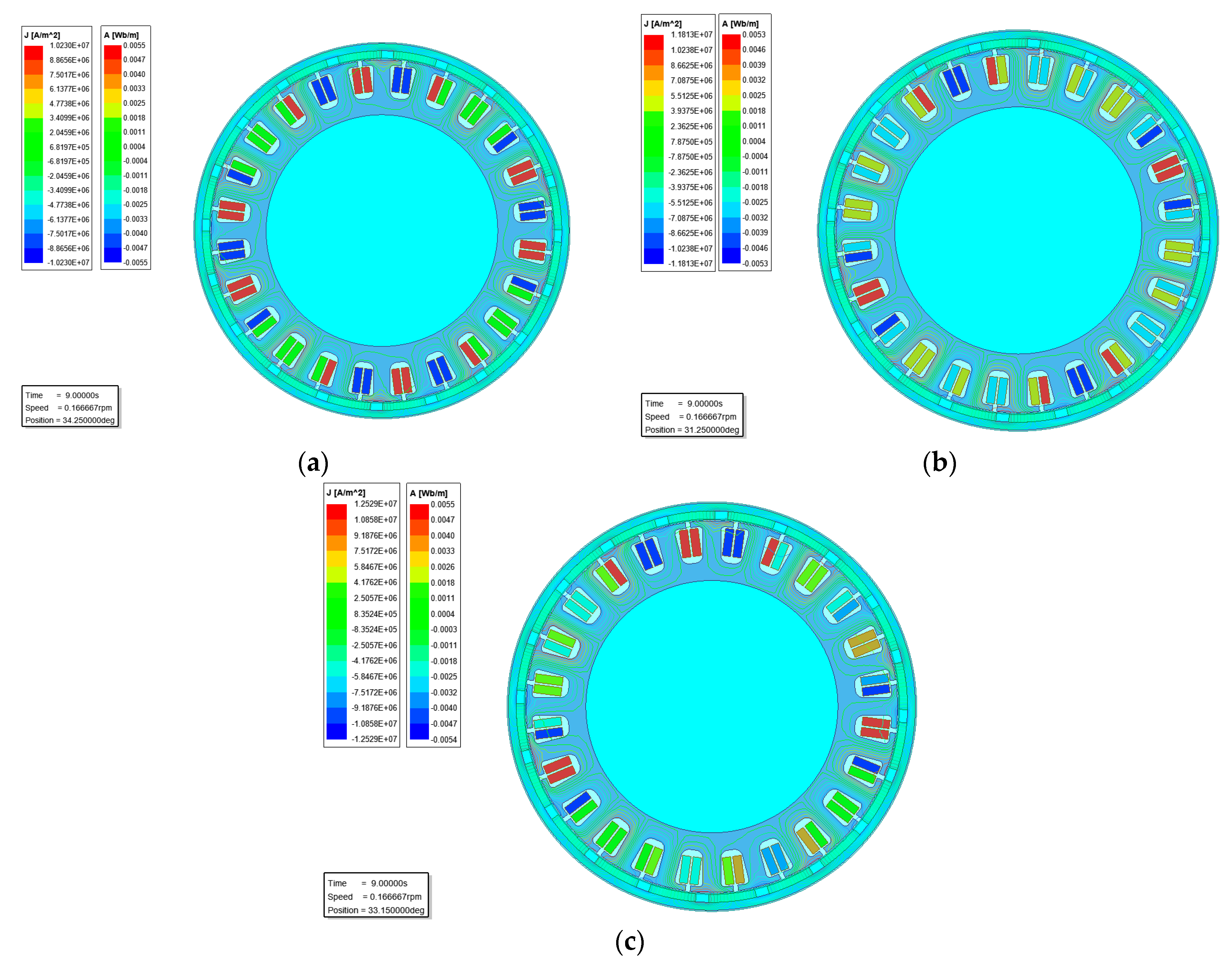
Using a program for performing numerical calculations in 2D FEM analysis [20], a simulation model was constructed. The 2D Finite Element Method (FEM) model allowed for the analysis of different stator winding configurations. Figure 3 shows an example distribution of magnetic flux lines and current densities for the three winding configurations: star (Figure 3a), delta (Figure 3b) and combined star–delta (Figure 3c).
The distribution of current densities varies depending on the analysed winding configuration. The magnetic radial forces depend on the air-gap flux density distribution. This distribution is significantly affected by the choice of winding configuration.

2.3. Static Characteristics

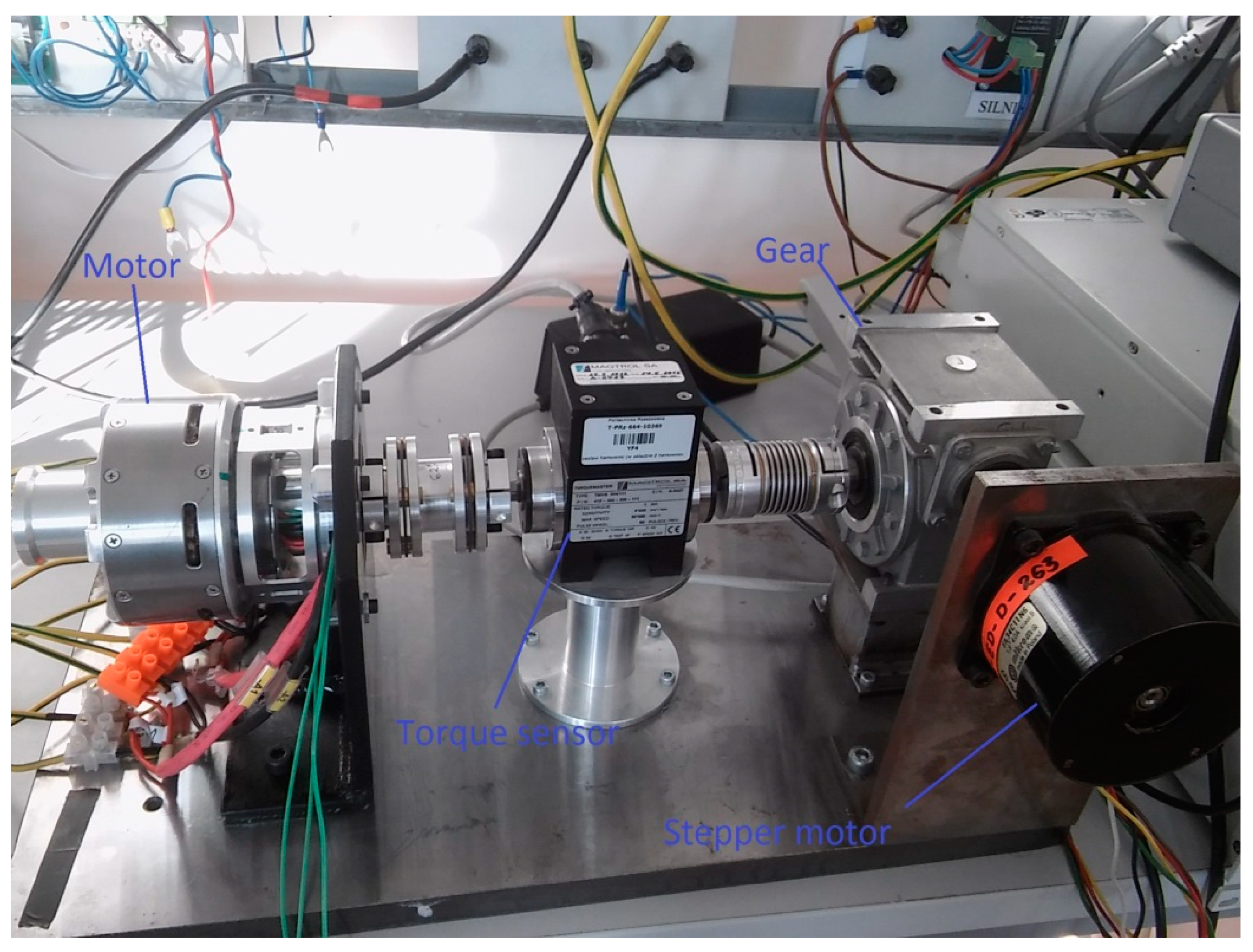
For the comparison of the analysed configurations, their static torque characteristics were determined. The star winding configuration was taken as the base configuration. For this configuration, the value of the supply current I Y was 10 A. In determining the currents for the other two configurations, it was assumed that the total copper loss P Cu was identical for each connection—i.e., P CuY = P Cu Δ = P CuY Δ . Based on this assumption, the following relationships were obtained for the currents in particular configurations: I Y = 3 I Δ = 3 2 I Y Δ . The static torque characteristics were determined both numerically and under laboratory conditions. The stand for the laboratory measurement of static characteristics is shown in Figure 4. Figure 5a shows the results of numerical calculations. The calculations were performed for only one electrical period, which corresponds to a mechanical angle of 36°. The characteristics obtained under laboratory conditions are shown in Figure 5b. In view of the electrical and magnetic asymmetries occurring in the tested prototype, the results for five electrical periods (corresponding to a mechanical angle of 180°) are shown.
Comparing the obtained static torque characteristics, it was observed that with, the same copper losses, the star and delta winding configurations produced practically the same effect. The torque characteristics were almost identical. This was also confirmed by the laboratory measurements (Figure 5b). In the case of the combined star–delta configuration, a smaller torque was obtained in both the numerical calculations (Figure 5a) and the laboratory measurements (Figure 5b). The torque characteristics obtained under laboratory conditions were similar to each other; a greater difference was observed for the numerical results in the case of the YΔ configuration. Table 1 provides the values obtained (numerically) for the torque constant KT for each configuration.
Assuming the same copper losses and identical winding parameters, the highest value of the torque constant was obtained for the star configuration, and the lowest was obtained for the delta configuration (by a factor of 3 ). In the YΔ case, the torque constant fell to approximately 81.6% of the value for the star configuration.

2.4. Back Electromotive Force (BEMF)

Back electromotive force computed numerically for the analysed configurations are shown in Figure 6. These are line-to-line voltages determined for the rotational speed n = 1000 rev/min.
Given identical winding parameters, the highest BEMF value is obtained for the star configuration. The BEMFs of the other configurations also differ in shape. The BEMF of the delta configuration is closest to a trapezoidal shape (third harmonic 26%; fifth harmonic 5%).
BEMF constants for all configurations are given in Table 2.
The BEMF constant KE is related to the torque constant KT. For the delta configuration, the BEMF constant was smaller by a factor of approximately 3 compared to the star configuration. This results from the relationship between the phase and line voltages. However, In the case of the YΔ configuration, this relationship to the star configuration was not maintained. The BEMF constant K E Y Δ was 76.6% of K E Y . In the case of the torque constant, the relationship was K T Y Δ = 2 3 K T Y = 81.6 % K T Y .

3. A Mathematical Model of the Analysed Brushless Direct Current Motor with Permanent Magnet (BLDCM)

Mathematical models are presented for BLDC machines with star (Y), delta (Δ) and star–delta (YΔ) winding configurations. The following simplifying assumptions were adopted in the model of the three-phase BLDC machine:
-
Symmetric cylindrical stator and permanent magnet type rotor, linear magnetic circuit;
-
Cogging and reluctance torques are neglected;
-
Phenomena relating to eddy currents and magnetic hysteresis are neglected—in particular, zero losses in the stator and rotor cores are assumed.

3.1. No-Constraints Phase Voltages, Three-Phase BLDC Star–Delta Model

The general structure of the mathematical model of the three-phase BLDC motor with combined star–delta (YΔ) windings can be written in the following form:
[ u 1 Y u 2 Y u 3 Y ] = [ R Y 0 0 0 R Y 0 0 0 R Y ] [ i 1 Y i 2 Y i 3 Y ] + [ L Y M Y M Y M Y L Y M Y M Y M Y L Y ] d d t [ i 1 Y i 2 Y i 3 Y ] + [ L Y Δ M Y Δ M Y Δ M Y Δ L Y Δ M Y Δ M Y Δ M Y Δ L Y Δ ] d d t [ i 1 Δ i 2 Δ i 3 Δ ] + [ e 1 Y e 2 Y e 3 Y ]
[ u 1 Δ u 2 Δ u 3 Δ ] = [ R Δ 0 0 0 R Δ 0 0 0 R Δ ] [ i 1 Δ i 2 Δ i 3 Δ ] + [ L Δ M Δ M Δ M Δ L Δ M Δ M Δ M Δ L Δ ] d d t [ i 1 Δ i 2 Δ i 3 Δ ] + [ L Δ Y M Δ Y M Δ Y M Δ Y L Δ Y M Δ Y M Δ Y M Δ Y L Δ Y ] d d t [ i 1 Y i 2 Y i 3 Y ] + [ e 1 Δ e 2 Δ e 3 Δ ]
J d ω m d t + D ω m + T L = T e
where total electromagnetic torque T e is given by:
T e = 1 ω m i = 1 3 ( e i Y i i Y + e i Δ i i Δ )
The following symbols are used in Equations (1)–(4) for i = 1 , 2 , 3 : u i Y , u i Δ —phase voltages; i i Y , i i Δ —phase currents; R Y , R Δ —phase resistances; L Y , M Y , L Δ , M Δ , L Y Δ = L Δ Y , M Y Δ = M Δ Y —self and mutual inductances; e i Y , e i Δ —phase BEMFs voltages; J—rotor moment of inertia; ω m —mechanical angular speed of rotor; D—rotor damping of viscous friction coefficient; T L —load torque.
The phase BEMF voltages for i = 1 , 2 , 3 in Equations (1), (2) and (4) are defined as follows:
e i Y = ω ψ i YPM ( θ ) θ = ω K E Y f i Y ( θ ( i 1 ) 2 π 3 ) e i Δ = ω ψ i Δ PM ( θ ) θ = ω K E Δ f i Δ ( θ ( i 1 ) 2 π 3 )
where θ—electrical rotor angle; ω = d θ / d t = p ω m —electrical angular speed; p—machine pole pairs; ψ i YPM ( θ ) , ψ i Δ PM ( θ ) —permanent magnetic fluxes linking the stator windings; K E Y , K E Δ —BEMF constant of one phase; f i Y ( ) , f i Δ ( ) —phase trapezoidal functions, profile BEMF. The phase BEMF functions can be expressed as ideal trapezoidal waveforms or as the summation of all harmonics in the Fourier series—for example, they can be expressed as follows:
e i Y = ω ν = 1 E i ν Y cos ( ν θ + θ i 0 Y ) ,   e i Δ = ω ν = 1 E i ν Δ cos ( ν θ + θ i 0 Δ )
where E i ν Y , E i ν Δ and θ i 0 Y , θ i 0 Δ are the amplitude (at 1 rad/s speed) and initial phase of the harmonic BEMF.
The total electromagnetic torque T e in Equation (4) is produced by an interaction between the rotor’s permanent magnets and the stator’s energized windings, and can be expressed as follows:
T e = i = 1 3 ( i i Y K T Y f i Y ( θ ( i 1 ) 2 π 3 ) + i i Δ K T Δ f i Δ ( θ ( i 1 ) 2 π 3 ) )
where K T Y , K T Δ —torque constants of one phase.
Additional constraints on voltages and currents are imposed by the arrangement of motor phase windings in a star (Y), delta (Δ) or combined star–delta (YΔ) configuration.

3.2. Star, Delta and Star–Delta Line Voltage Models

The relationship of phase currents i i Y ( i = 1 , 2 , 3 ) in a star (Y) configuration and phase voltages u i Δ ( i = 1 , 2 , 3 ) in a delta (Δ) configuration can be written as follows:
Star   ( Y ) :   i = 1 3 i i Y = 0 ; Delta   ( Δ ) :   i = 1 3 u i Δ = 0
The relationship between the line-to-line and phase voltages and line and phase currents in the star (Y) and delta (Δ) configurations can be written as follows:
Star   ( Y ) :   [ u 12 u 23 u 31 ] = [ 1 1 0 0 1 1 1 0 1 ] [ u 1 Y u 2 Y u 3 Y ] ;   [ i 1 i 2 i 3 ] = [ i 1 Y i 2 Y i 3 Y ]
Delta   ( Δ ) :   [ u 12 u 23 u 31 ] = [ u 1 Δ u 2 Δ u 3 Δ ] ; [ i 1 i 2 i 3 ] = [ 1 0 1 1 1 0 0 1 1 ] [ i 1 Δ i 2 Δ i 3 Δ ]
Including the constraint Equations (9) and (10), the final equations of the BLDC motor models can be written for the Y, Δ and YΔ configurations. The model line-to-line voltages and the line currents, phase BEMF voltages and total electromagnetic torques can be written as follows.
  • Model for star (Y) winding BLDC motor
    [ u 12 u 23 u 31 ] = [ 2 R Y 0 R Y R Y 2 R Y 0 0 R Y 2 R Y ] [ i 1 Y i 2 Y i 3 Y ] + [ 2 ( L Y M Y ) 0 L Y M Y L Y M Y 2 ( L Y M Y ) 0 0 L Y M Y 2 ( L Y M Y ) ] d d t [ i 1 Y i 2 Y i 3 Y ] + [ e 1 Y e 2 Y e 2 Y e 3 Y e 3 Y e 1 Y ]
    [ i 1 i 2 i 3 ] = [ i 1 Y i 2 Y i 3 Y ] ;   e i Y = ω K E Y f i Y ( θ ( i 1 ) 2 π 3 ) ;   T e Y = i = 1 3 ( i i Y K T Y f i Y ( θ ( i 1 ) 2 π 3 ) )
  • Model for delta (Δ) winding BLDC motor
    [ u 12 u 23 u 31 ] = [ R Δ 0 0 0 R Δ 0 0 0 R Δ ] [ i 1 Δ i 2 Δ i 3 Δ ] + [ L Δ M Δ M Δ M Δ L Δ M Δ M Δ M Δ L Δ ] d d t [ i 1 Δ i 2 Δ i 3 Δ ] + [ e 1 Δ e 2 Δ e 3 Δ ]
    [ i 1 i 2 i 3 ] = [ 1 0 1 1 1 0 0 1 1 ] [ i 1 Δ i 2 Δ i 3 Δ ] ;   e i Δ = ω K E Δ f i Δ ( θ ( i 1 ) 2 π 3 ) ;   T e Δ = i = 1 3 ( i i Δ K T Δ f i Δ ( θ ( i 1 ) 2 π 3 ) )
  • Model for star–delta (YΔ) winding BLDC motor
    [ u 12 u 23 u 31 ] = [ R R Y R Y R Y R R Y R Y R Y R ] [ i 1 Δ i 2 Δ i 3 Δ ] + [ L M M M L M M M L ] d d t [ i 1 Δ i 2 Δ i 3 Δ ] + [ e 1 Y e 2 Y + e 1 Δ e 2 Y e 3 Y + e 2 Δ e 3 Y e 1 Y + e 3 Δ ]
    [ i 1 i 2 i 3 ] = [ i 1 Y i 2 Y i 3 Y ] = [ 1 0 1 1 1 0 0 1 1 ] [ i 1 Δ i 2 Δ i 3 Δ ] ; T e = T e Y + T e Δ
The equivalent motor parameters in Equation (15) are determined by the following relationships:
R = 2 R Y + R Δ ;   L = 2 ( L Y M Y ) + L Δ + 2 ( L Y Δ M Y Δ ) ;   M = L Y + M Y + M Δ L Y Δ + M Y Δ
The phase BEMF voltages K T Y , K T Δ ( i = 1 , 2 , 3 ) in Equation (15) and the torques T e Y , T e Δ in Equation (16) are defined in Equations (12) and (14).
Equations (3) and (11)–(16) constitute the mathematical models of BLDC motors with star (Y), delta (Δ) and star–delta (YΔ) winding configurations.

4. Comparative Analysis, Simulation and Experimental Verification

All numerical calculations and laboratory tests were carried out in a fixed operating state for different rotational speeds. The numerical results are presented here for only a speed of 500 r/min. The supply voltage was varied, taking account of the BEMF constants kV for particular configurations (Table 2). In the laboratory tests, to obtain the required operating point, the value of the load torque was varied.

4.1. Star Configuration—Transient Analysis in Healthy Mode and under Open Phase Fault

4.1.1. Waveforms of Electromagnetic Torque and Currents

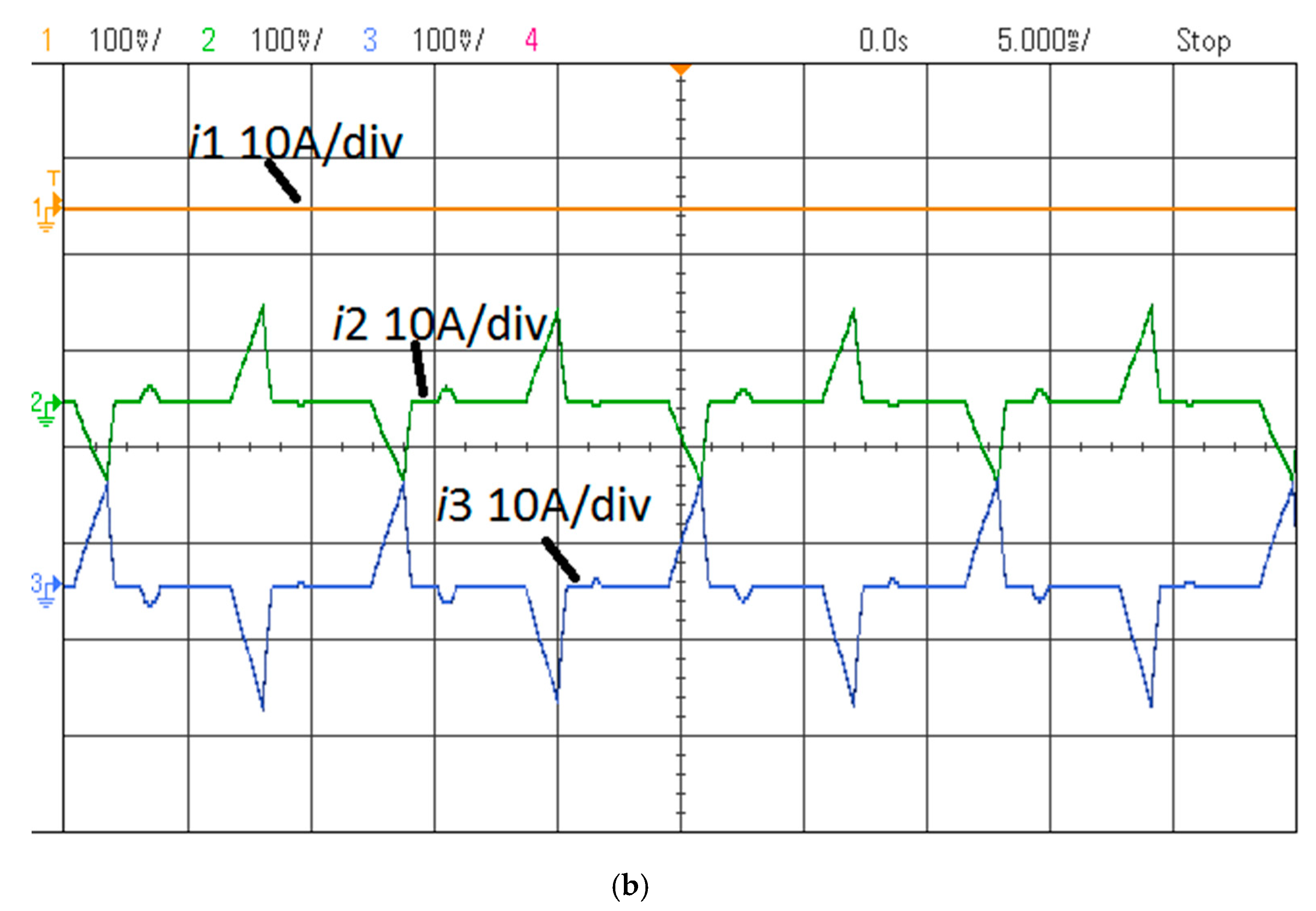
The star winding configuration is shown in Figure 1b. Opening the switch OC1 breaks the supply in the phase Ph1. The effects of the open circuit state on the produced electromagnetic torque and line currents are shown in Figure 7, Figure 8a, and Figure 9a. The current waveforms obtained under laboratory conditions for the analysed operating states are shown in Figure 8b and Figure 9b.
Opening the switch OC1 (Figure 1b) causes the whole of phase Ph1 to be switched off. In this case, the motor operates in two phases only. This means that four out of six control sequences cannot be applied. If the fault occurs during operation, the motor can continue to function, but only at a small load torque (below 20% of the rated value).

4.1.2. FFT of u0

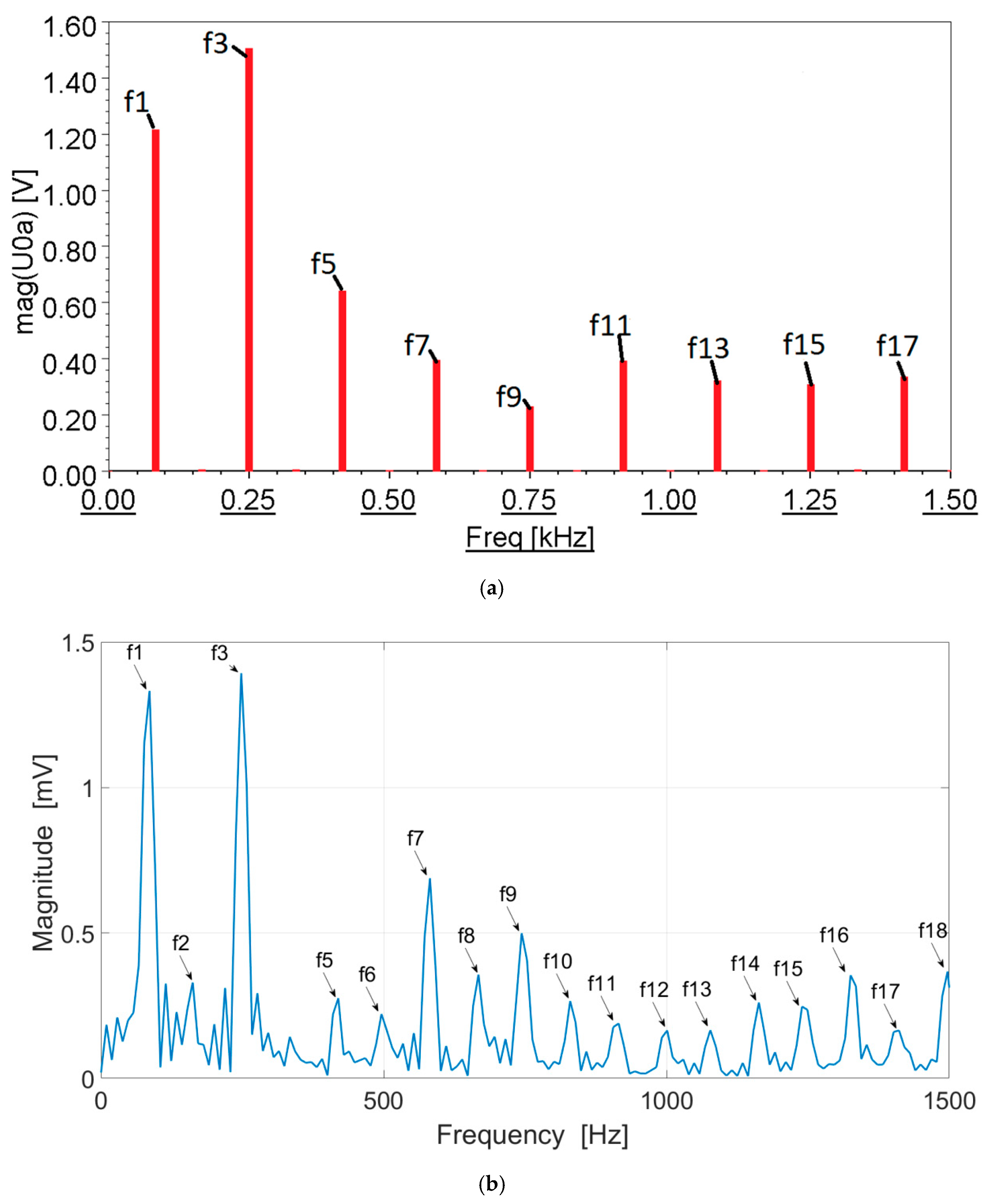
Waveforms of the voltage u0 were recorded for the analysed states (Figure 1a). Using harmonic analysis (FFT), significant harmonics present in the voltage signal, u0, were identified (Figure 1a). Figure 10 shows the content of higher harmonics for the star configuration under normal operation (numerical calculations in Figure 10a; measurements in Figure 10b). The content of higher harmonics of the voltage signal in fault state OC1 is shown in Figure 11a (numerical calculations) and Figure 11b (measurements).
The fundamental frequency f1 of the voltage signal u0 depends on the rotational speed n and on the design parameter p and the number of pole pairs of the rotor.
f 1 = p n 60
In a state of electrical and magnetic symmetry, the voltage signal u0 contains only the third harmonic and its odd multiples (the 9th, 15th, etc.), as can be seen in Figure 10a. In practice, most electrical machines have electrical and magnetic asymmetries to a greater or lesser degree, usually arising during the technological process. Under laboratory conditions, the appearance of other harmonics that were multiples of three was observed (the 6th, 12th, 18th, etc.; see Figure 10b).
In the fault state OC1, all odd harmonics appeared in the voltage signal u0 (the first, third, fifth, seventh, etc.). This is visible in Figure 11a. In real conditions, not all odd harmonics were present—for example, the fifth harmonic was absent (Figure 11b). Additionally, the even harmonic f2 appeared in the spectrum. The appearance in the voltage signal of the harmonic f1 with an amplitude comparable to that of f3 indicates an open circuit in one of the phases of the motor.

4.2. Delta Configuration—Transient Analysis in Healthy Mode and Under Open Phase Fault

The delta winding configuration is shown in Figure 1c. As with the star configuration, an analysis of the symmetrical operation of the motor and its operation in a fault state was performed. Opening the switch OC1 caused a break in the conventional phase Ph1. However, unlike in the case of the star winding configuration, the motor still received a full six-step supply.

4.2.1. Delta (Δ) Configuration—Waveforms of Electromagnetic Torque and Currents

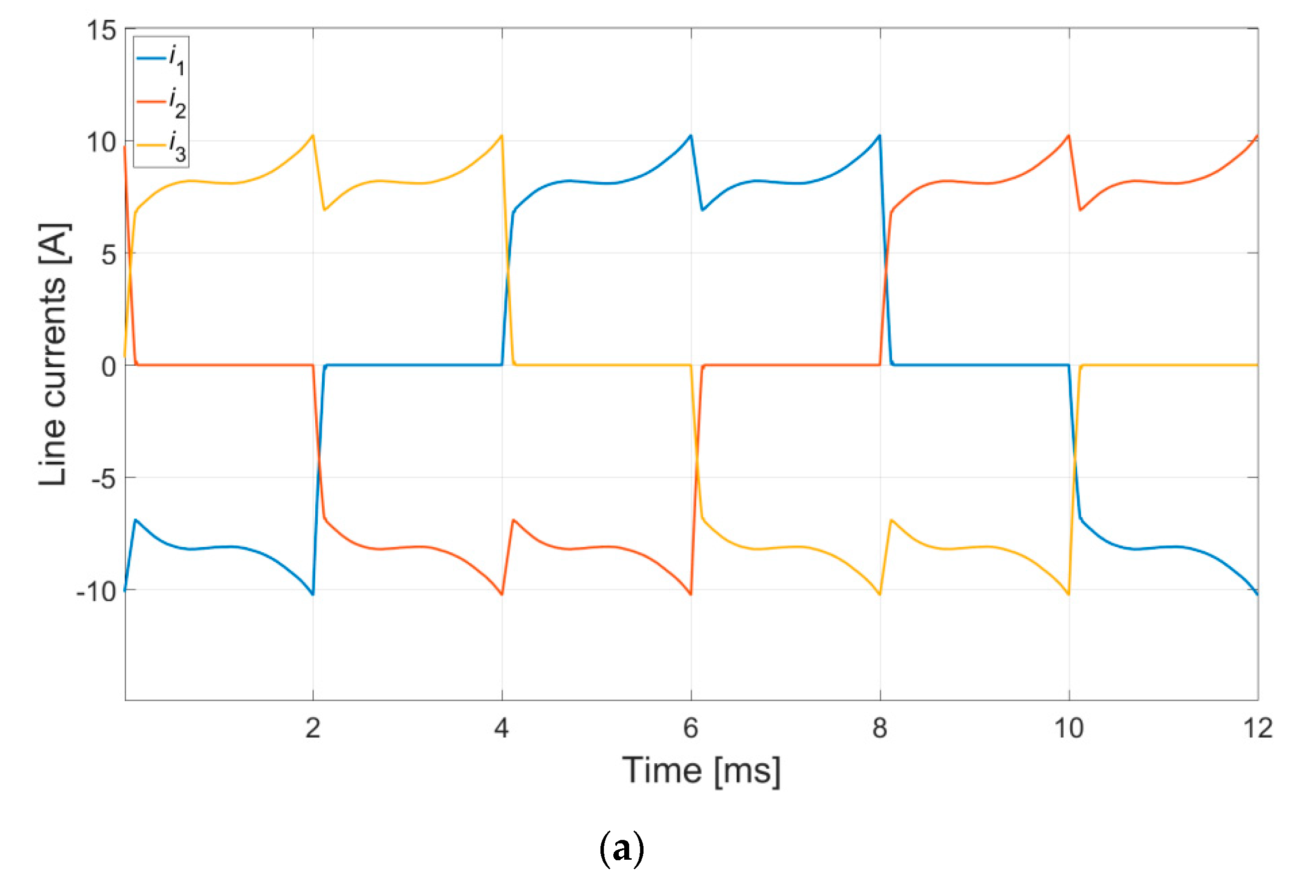
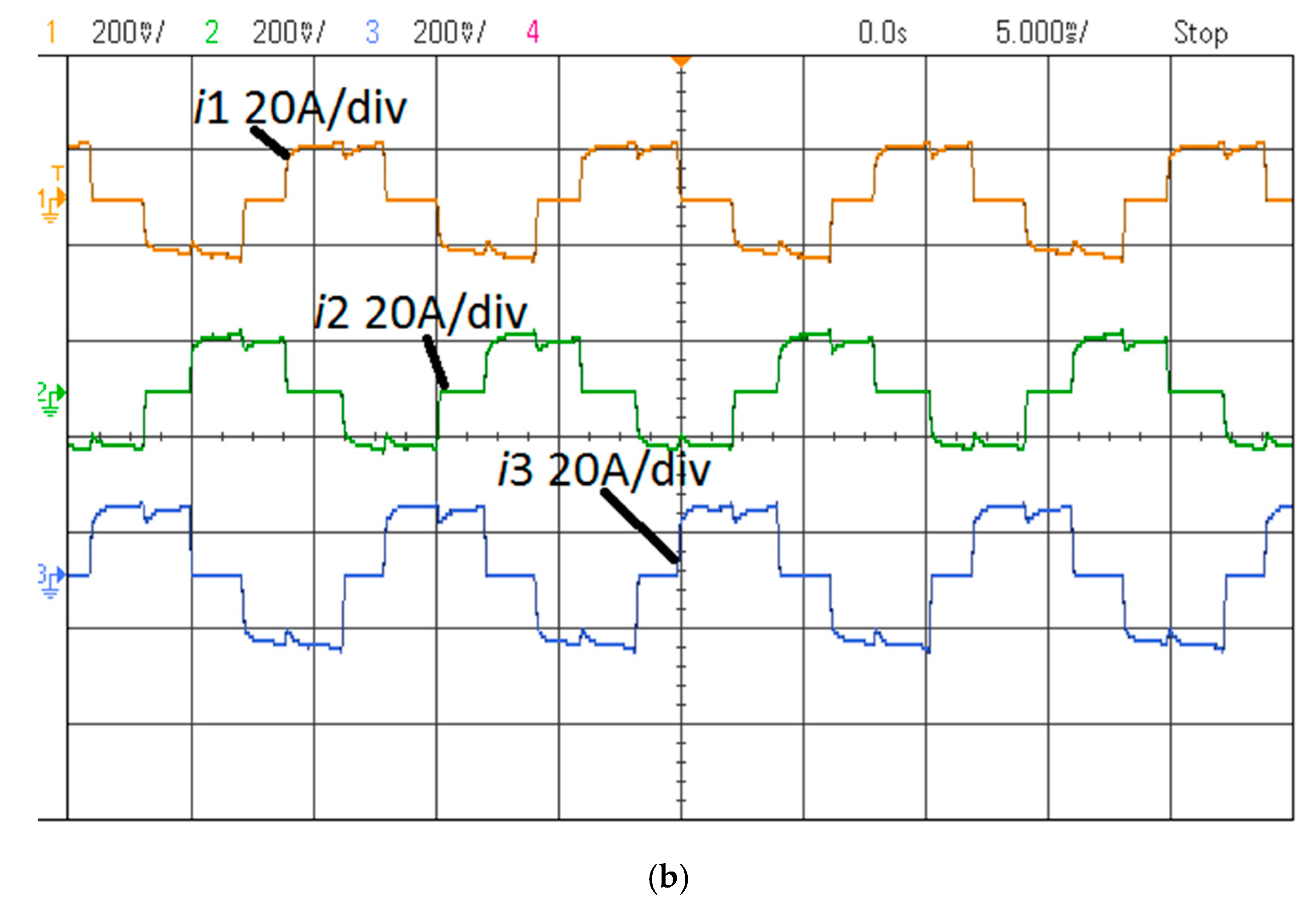
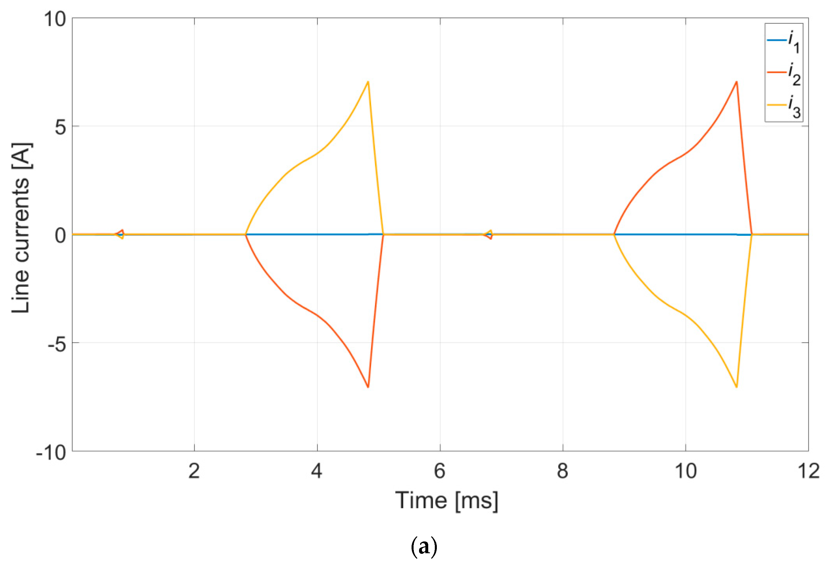
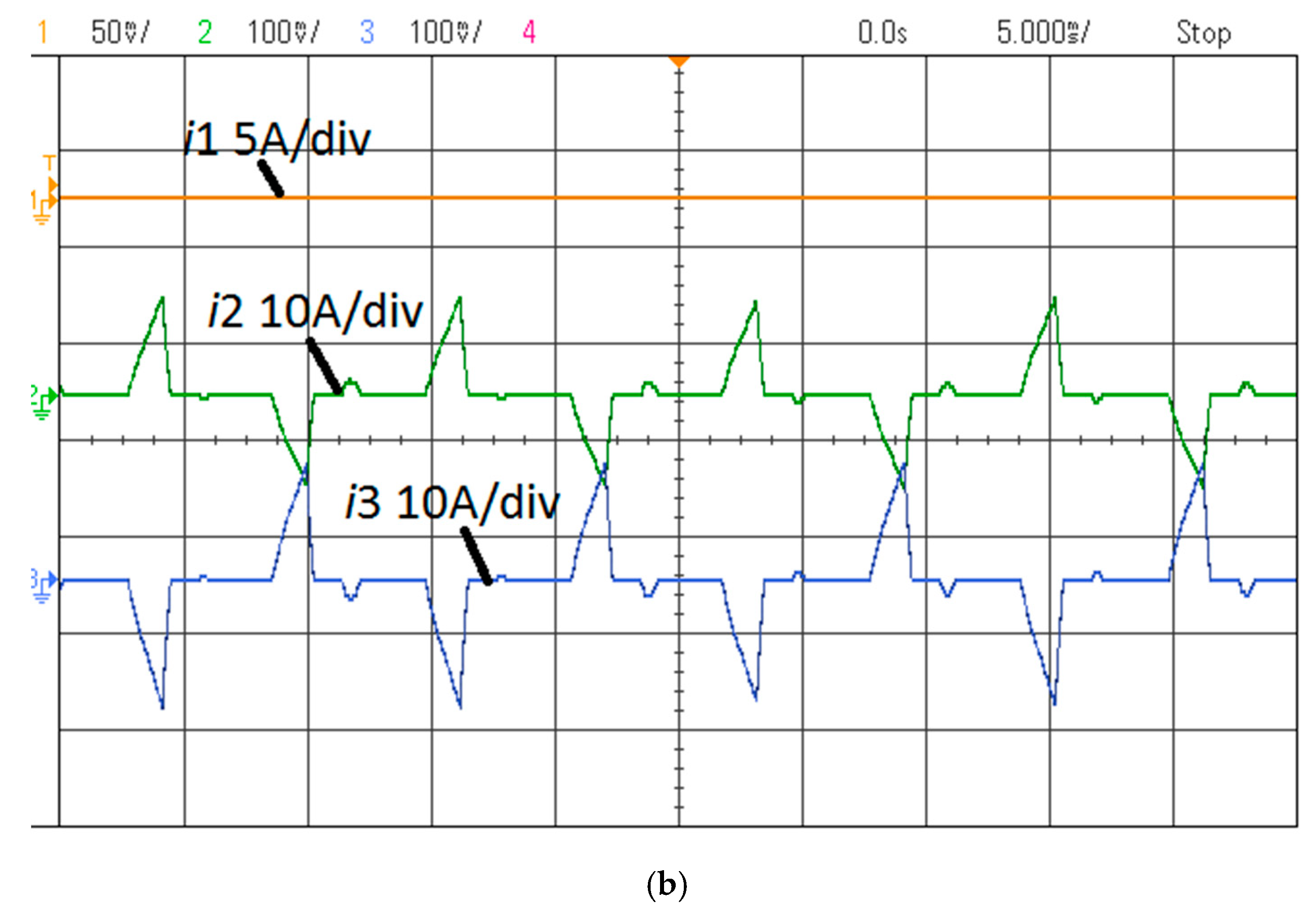
The waveforms of electromagnetic torque and line currents for the analysed states of operation are shown in Figure 12, Figure 13 and Figure 14.
The fault state OC1 caused by an open circuit in the conventional phase Ph1 had a negative impact on the value of the produced electromagnetic torque. The mean value of the torque decreased, simultaneous to a significant increase in torque ripple (Figure 12). There was a significant change in the waveforms of the line currents (Figure 14). The RMS values of line currents differed between phases. Greater differences were observed under laboratory conditions (Figure 14b). As with the star configuration, the motor could continue to operate with the load torque reduced by several tens of percent. The drive system could also be restarted after stopping.

4.2.2. FFT of u0

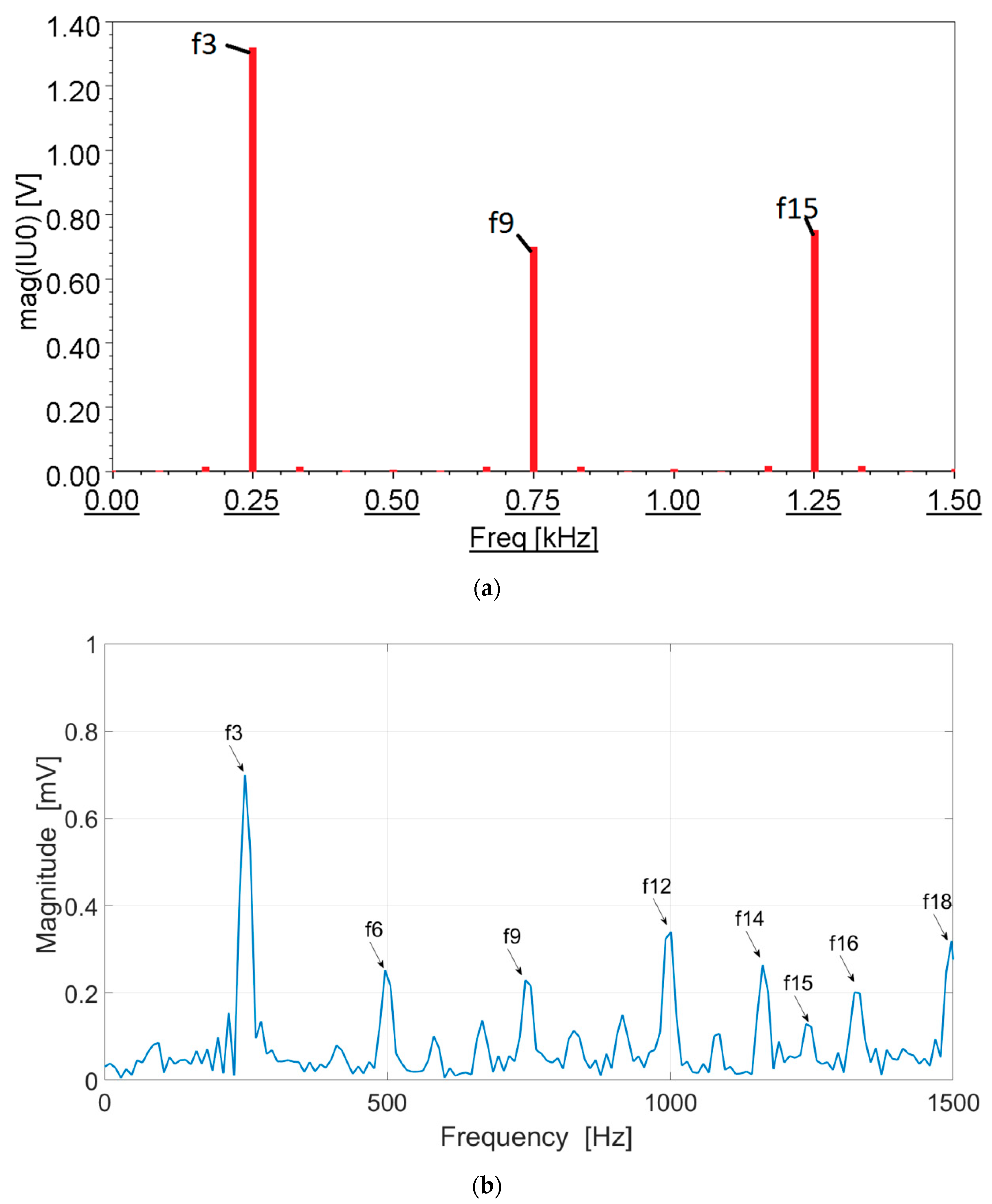
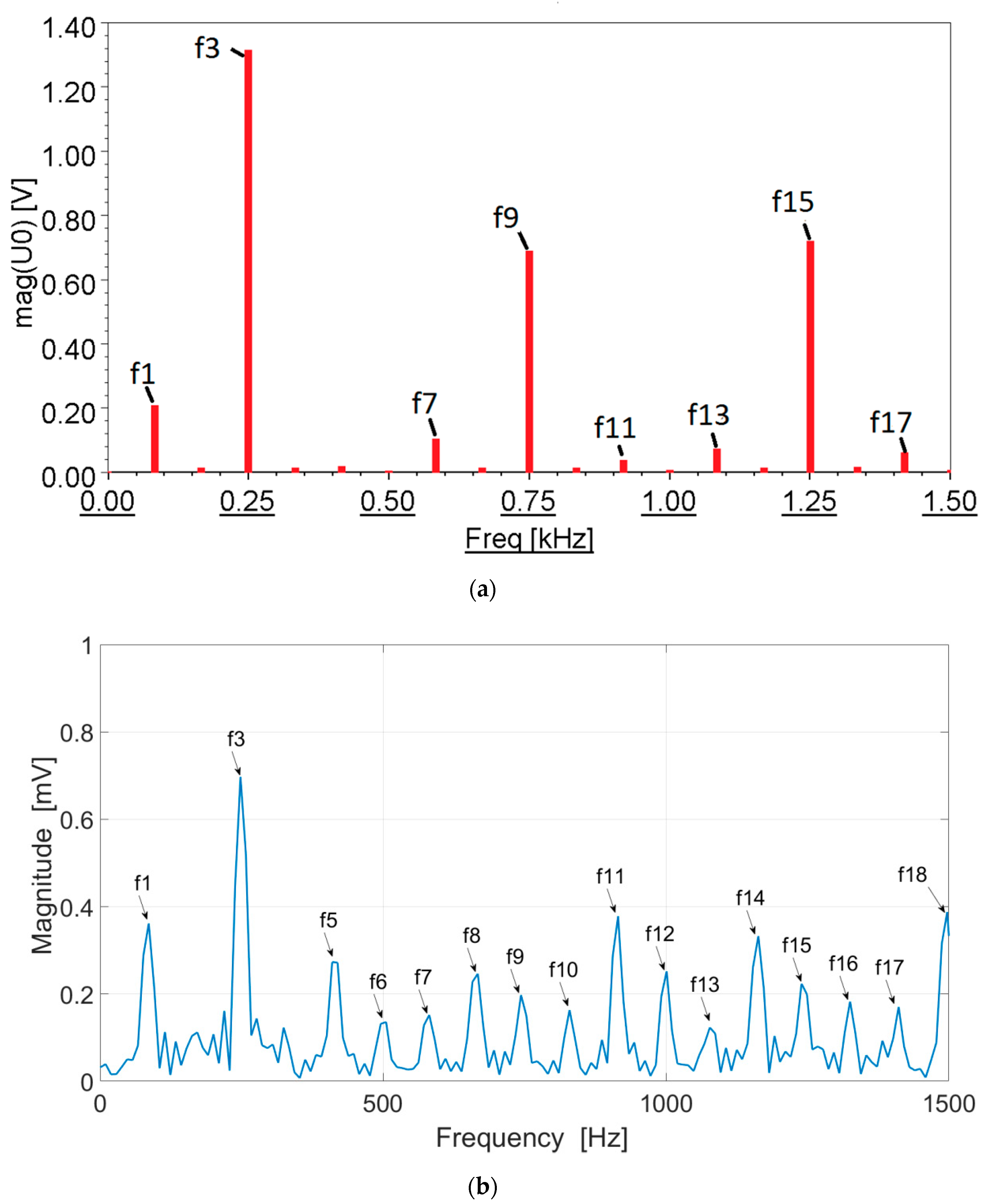
For the delta configuration, based on harmonic analysis (FFT), the harmonics present in the voltage signal u0 were identified. Analysis was performed for normal operation and for a fault state. The results of numerical calculations and laboratory measurements for normal operation are shown in Figure 15. Figure 16 shows the analysis of higher harmonics for the OC1 fault state.
As with the star configuration, the voltage signal u0 for normal operation contains only the third harmonic and its odd multiples. The amplitude of the third harmonic was dominant in both the numerical calculations (Figure 15a) and the laboratory results (Figure 15b). In the practical setup, even multiples of the third harmonic also appeared (the 6th, 12th, 18th, etc.). This is a result of the electrical and magnetic asymmetry of the tested motor. The OC fault state caused a significant change in the content of harmonics of the voltage u0. As in the star case, all odd harmonics appeared (Figure 16). In both the numerical calculations (Figure 16a) and the laboratory tests (Figure 16b), the appearance of the first harmonic was significant. Depending on the type of testing (numerical, experimental), the amplitude of this harmonic was 50% (or more) of the amplitude of the third harmonic. Under laboratory conditions, the ninth harmonic was practically absent in the fault state.

4.3. Star–Delta Configuration—Transient Analysis in Healthy Mode and Under Open Phase Fault

The YΔ type winding configuration is a combination of the well-known Y and Δ configurations (Figure 1d). In the case analysed, one half of the windings were connected in a delta arrangement. Analysis of the case of a fault state caused by an open circuit in one of the phases required consideration of two alternative scenarios. In the first scenario, the fault was produced by opening the key OC1. This was a situation very similar to the OC fault state for a star configuration. In the second scenario, when the key OC2 was opened (Figure 1d), the open circuit in the conventional phase Ph1 occurred in the delta part of the configuration. This case was similar, but not identical, to the case of an OC fault in a delta configuration.

4.3.1. Waveforms of Electromagnetic Torque and Currents

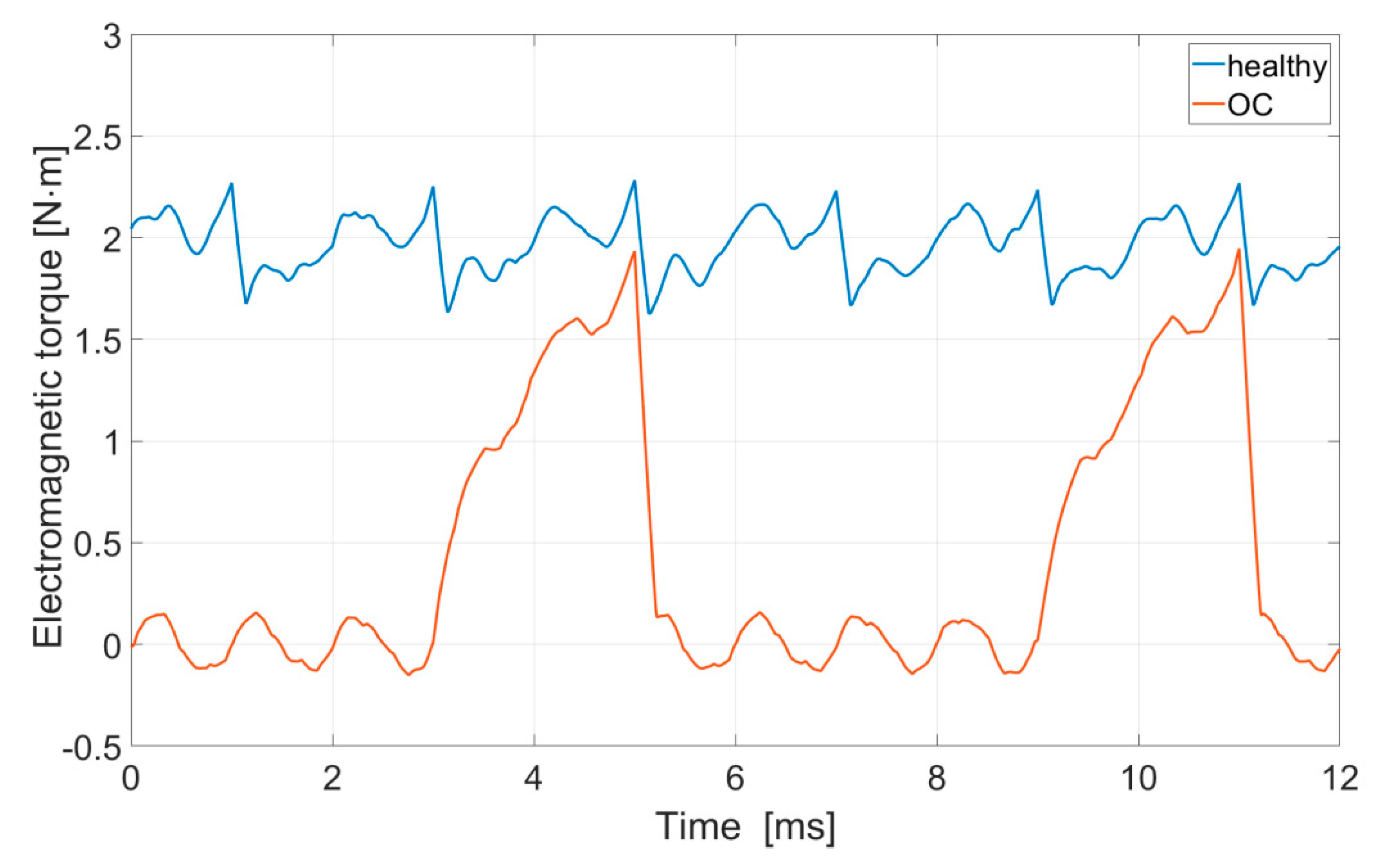
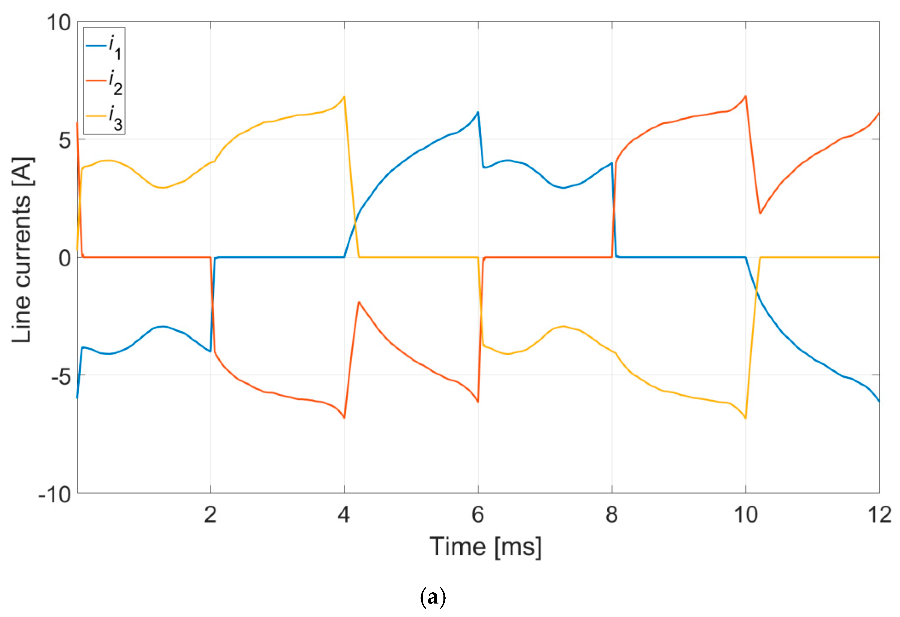
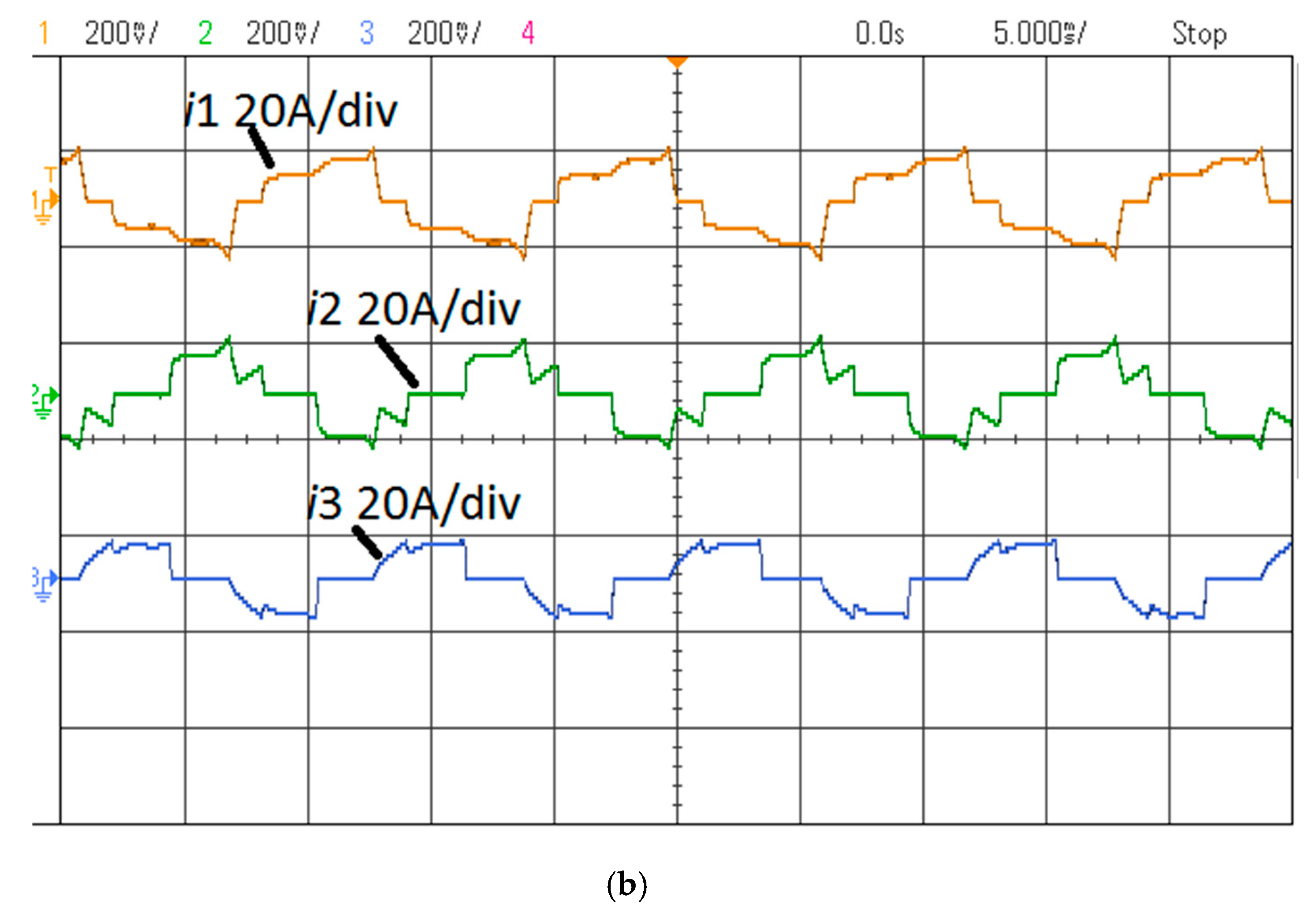
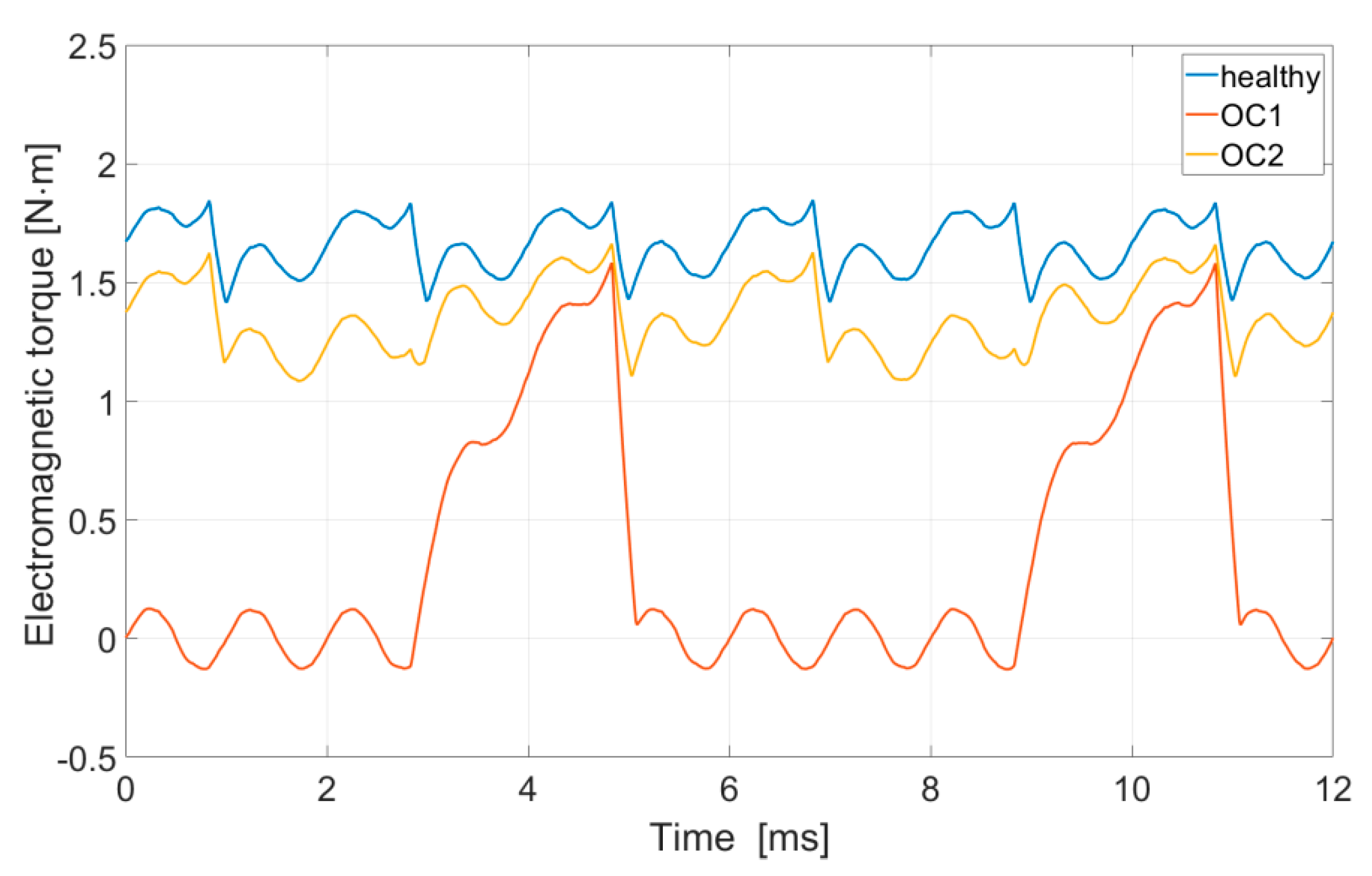
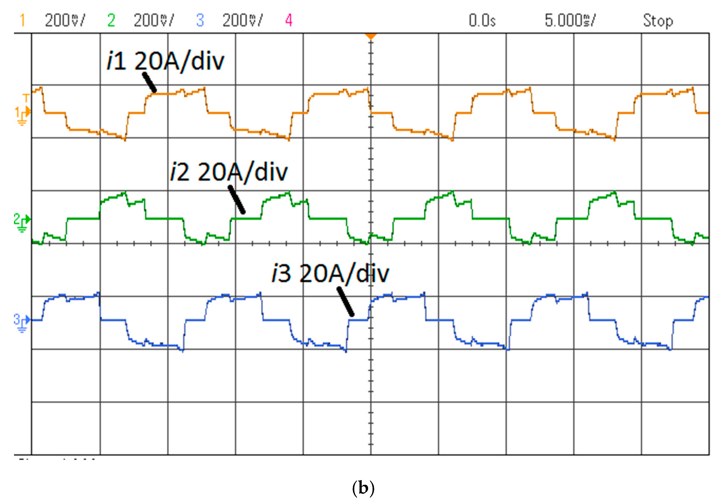
The waveforms of electromagnetic torque (Figure 17) show the effect of the analysed fault states. Figure 18 shows the waveforms of line currents under normal operation. The waveforms of line currents in the analysed fault states are shown in Figure 19 (OC1) and Figure 20 (OC2).
Opening the switch OC1 (Figure 1d) caused an open circuit in the phase Ph1. The result of this, as in the case of the star configuration, was that only two steps of the available six were used. The consequences of the fault were also almost identical. The motor could operate in the fault state only with a significantly reduced load torque. The torque ripple increased by several hundred percent. If the open circuit was caused by the opening of the switch OC2, the consequences of the fault were less serious. There was a relatively small decrease in the electromagnetic torque generated (Figure 17) and a relatively small increase in ripple. The motor could continue to operate in all conditions. The changes in the waveforms of the line currents were also relatively minor (Figure 20). Relatively small differences were observed in the effective values of the particular line currents.

4.3.2. FFT of u0

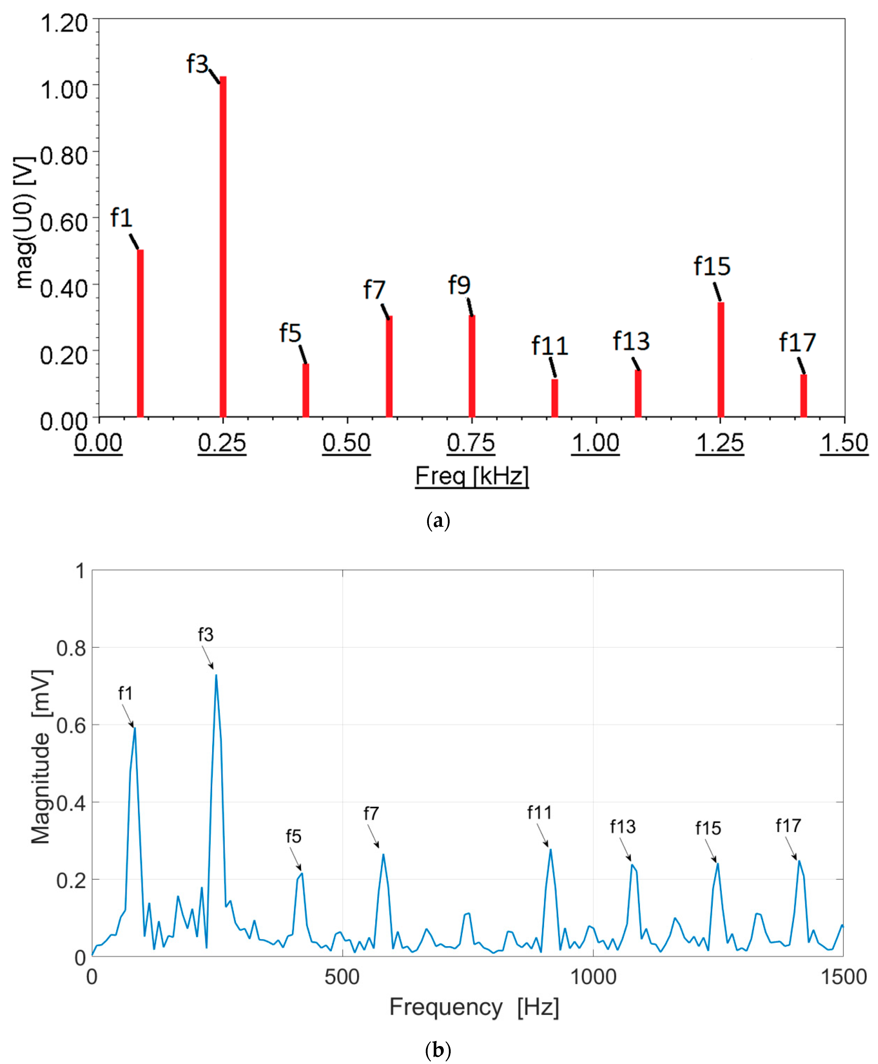
For the analysed states, the waveform of the voltage u0 was recorded for the YΔ configuration. Based on harmonic analysis (FFT), the significant harmonics present in the voltage signal u0 were identified. The contents of higher harmonics are shown in Figure 21 for a normal operating state, in Figure 22 for fault state OC1, and in Figure 23 for fault state OC2.
In the healthy mode laboratory tests (Figure 21b), as in the case of the Y and Δ configurations, even multiples of the third harmonic appeared. Other harmonics also appeared, such as the 14th and 16th. However, in comparison with the cases of the Y and Δ configurations, the contribution of the third harmonic was dominant. This was not observed in the results of the numerical calculations (Figure 21a).
Fault state OC1 caused the appearance of the first harmonic, which is dominant for this state (Figure 22). Other odd harmonics also appeared—for example, the fifth (in the numerical calculations only) and the seventh. In the real system, the appearance of, for example, the second harmonic was also observed.
In fault state OC2, odd harmonics, such as the first, fifth and seventh appeared again. However, the appearance of the first harmonic, with an amplitude not exceeding 50% of the value of the third harmonic, is significant here.

4.4. Comparative Analysis in Healthy Mode and Under Open Phase Fault

To verify the state of symmetrical operation and fault states under laboratory conditions, the noise level and acceleration were recorded. This was done at the same load torque (0.5 Nm) and rotational speed (1000 r/min). The results are given in Table 3.
At the same operating point, the lowest noise level was produced by the YΔ configuration. The level of vibrations was also the lowest. However, the differences, relative to the Y and Δ configurations were, suboptimal. The situation was changed by an open circuit in one of the phases. Depending on the configuration, vibrations and noise may increase significantly (for the Y configuration and for OC1 in the YΔ configuration), although a lower noise level was recorded in the YΔ OC1 case (70.4 dB, compared with 72.1 dB for Y). In the case of an open circuit in the Δ configuration, or for OC2 in the YΔ configuration, the vibration and noise levels remained practically unchanged.
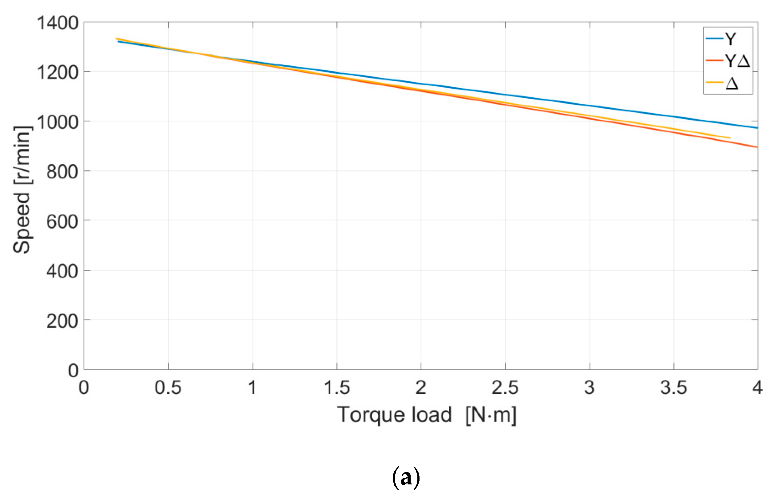
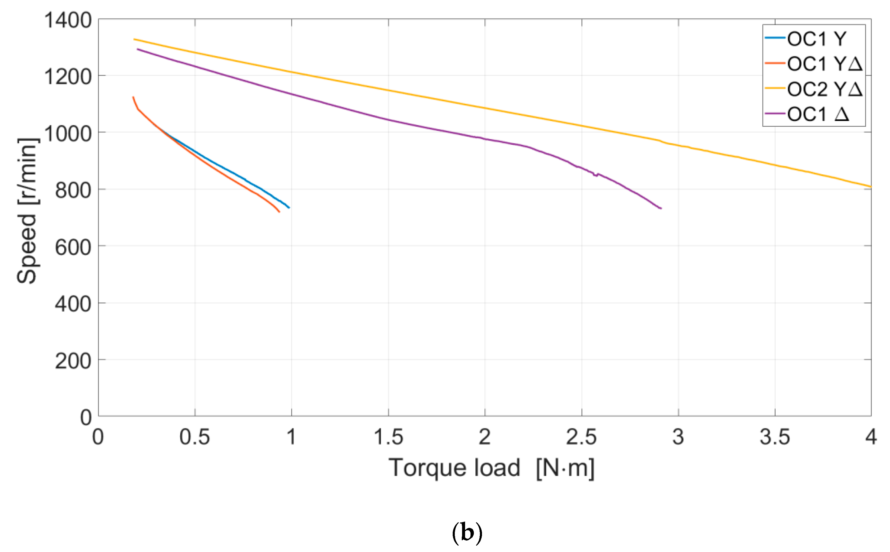
Torque–speed characteristics for the particular configurations under symmetrical operation and in fault states are shown in Figure 24. Overall efficiency, determined by a direct method, is shown in Figure 25.
The torque–speed characteristics for the YΔ and Δ configurations were less rigid. This is a result of the greater voltage drop between the power source and the system (higher current Idc). The highest overall efficiency was provided by the delta configuration. The YΔ configuration had higher efficiency under partial load. For higher loads, its efficiency was the lowest of all those analysed.

5. Conclusions

The type of winding configuration used has an impact on the operation of a BLDC motor. A combined star–delta configuration does not produce significant advantages in normal operation. Under laboratory conditions, slightly lower levels of vibrations and noise were obtained, but the efficiency of the drive system was lower than in the case of the delta configuration. Differences appeared in the case of a fault caused by an open circuit in one of the phases. For the combined star–delta configuration, if the open circuit occurred in the delta part, this was the best tolerated fault case, with the load capacity of the motor reduced by less than 20% and the levels of vibrations and noise remaining almost unchanged. For the detection of fault states, the artificial neutral-point voltage can be used. In the voltage signal for normal operation, the third harmonic and its odd multiples were present. Any electrical or magnetic asymmetries or faults in the operation of the system produce changes in the content of higher harmonics in this signal. An open-circuit fault will cause all odd harmonics to appear in the voltage signal. The amplitude of the first harmonic is a key indicator. In the case of an open circuit in a star configuration or in the star part of a combined star–delta configuration, the amplitude of the first harmonic is comparable to that of the third harmonic. For a fault in a delta configuration or in the delta part of a combined configuration, the first harmonic does not exceed 50% of the value of the third harmonic. This is not the only fault state that may occur during operation of the motor.
Further research by the authors will include the analysis of other fault states of the analysed winding configurations, such as short circuits of turns or whole windings, and faults on the side of the supply converter.

Author Contributions

Conceptualization, M.K. and B.P.; methodology, J.P. and M.K.; software, M.K. and B.P.; validation, M.K. and J.P.; formal analysis, J.P.; investigation, M.K., J.P. and B.P.; resources, M.K.; data curation, B.P.; writing—original draft preparation, M.K.; writing—review and editing, M.K., B.P., J.P, P.B. and G.P.; visualization, M.K. and B.P.; supervision, J.P.; project administration, M.K.; funding acquisition, M.K. All authors have read and agreed to the published version of the manuscript.

Funding

This work is financed in part by the statutory funds (UPB) of the Department of Electrodynamics and Electrical Machine Systems, Rzeszow University of Technology and in part by Polish Ministry of Science and Higher Education under the program “Regional Initiative of Excellence” in 2019–2022. Project number 027/RID/2018/19, amount granted 11 999 900 PLN.

Conflicts of Interest

The authors declare no conflict of interest.

References

  1. Zhou, R.; Li, G.; Wang, Q.; He, J. Torque Calculation of Permanent-Magnet Spherical Motor Based on Permanent-Magnet Surface Current and Lorentz Force. IEEE Trans. Magn. 2020, 56, 1–9. [Google Scholar] [CrossRef]
  2. Onsal, M.; Cumhur, B.; Demir, Y.; Yolacan, E.; Aydin, M. Rotor Design Optimization of a New Flux-Assisted Consequent Pole Spoke-Type Permanent Magnet Torque Motor for Low-Speed Applications. IEEE Trans. Magn. 2018, 54, 1–5. [Google Scholar] [CrossRef]
  3. Li, Z.; Chen, Q.; Wang, Q. Analysis of Multi-Physics Coupling Field of Multi-Degree-of-Freedom Permanent Magnet Spherical Motor. IEEE Trans. Magn. 2019, 55, 1–5. [Google Scholar] [CrossRef]
  4. Wei, Y.; Xu, Y.; Zou, J.; Li, Y. Current Limit Strategy for BLDC Motor Drive with Minimized DC-Link Capacitor. IEEE Trans. Ind. Appl. 2015, 51, 3907–3913. [Google Scholar] [CrossRef]
  5. Shao, J. An Improved Microcontroller-Based Sensorless Brushless DC (BLDC) Motor Drive for Automotive Applications. IEEE Trans. Ind. Appl. 2006, 42, 1216–1221. [Google Scholar] [CrossRef]
  6. Zhu, J.; Bai, H.; Wang, X.; Li, X. Current Vector Control Strategy in a Dual-Winding Fault-Tolerant Permanent Magnet Motor Drive. IEEE Trans. Energy Convers. 2018, 33, 2191–2199. [Google Scholar] [CrossRef]
  7. Niu, S.; Luo, Y.; Fu, W.; Zhang, X. An Indirect Reference Vector-Based Model Predictive Control for a Three-Phase PMSM Motor. IEEE Access 2020, 8, 29435–29445. [Google Scholar] [CrossRef]
  8. Khan, K.R.; Miah, M.S. Fault-Tolerant BLDC Motor-Driven Pump for Fluids with Unknown Specific Gravity: An Experimental Approach. IEEE Access 2020, 8, 30160–30173. [Google Scholar] [CrossRef]
  9. Chun, T.; Tran, Q.; Lee, H.; Kim, H. Sensorless Control of BLDC Motor Drive for an Automotive Fuel Pump Using a Hysteresis Comparator. IEEE Trans. Power Electron. 2014, 29, 1382–1391. [Google Scholar] [CrossRef]
  10. Kumar, R.; Singh, B. Grid Interactive Solar PV-Based Water Pumping Using BLDC Motor Drive. IEEE Trans. Ind. Appl. 2019, 55, 5153–5165. [Google Scholar] [CrossRef]
  11. Ferreira, F.J.T.E.; Baoming, G.; de Almeida, A.T. Stator Winding Connection-Mode Management in Line-Start Permanent Magnet Motors to Improve Their Efficiency and Power Factor. IEEE Trans. Energy Convers. 2013, 28, 523–534. [Google Scholar] [CrossRef]
  12. Ibrahim, M.N.F.; Rashad, E.; Sergeant, P. Performance Comparison of Conventional Synchronous Reluctance Machines and PM-Assisted Types with Combined Star–DeltaWinding. Energies 2017, 10, 1500. [Google Scholar] [CrossRef]
  13. Misir, O.; Morteza Raziee, S.; Hammouche, N.; Klaus, C.; Kluge, R.; Ponick, B. Prediction of Losses and Efficiency for Three-Phase Induction Machines Equipped with Combined Star–Delta Windings. IEEE Trans. Ind. Appl. 2017, 53, 3579–3587. [Google Scholar] [CrossRef]
  14. Lei, Y.; Zhao, Z.; Wang, S.; Dorrell, D.G.; Xu, W. Design and Analysis of Star–Delta Hybrid Windings for High-Voltage Induction Motors. IEEE Trans. Ind. Electron. 2011, 58, 3758–3767. [Google Scholar] [CrossRef]
  15. Song, X.; Han, B.; Zheng, S.; Fang, J. High-Precision Sensorless Drive for High-Speed BLDC Motors Based on the Virtual Third Harmonic Back-EMF. IEEE Trans. Power Electron. 2018, 33, 1528–1540. [Google Scholar] [CrossRef]
  16. Ullah, Z.; Hur, J. A Comprehensive Review of Winding Short Circuit Fault and Irreversible Demagnetization Fault Detection in PM Type Machines. Energies 2018, 11, 3309. [Google Scholar] [CrossRef] [Green Version]
  17. Yang, S. Online Stator Turn Fault Detection for Inverter-Fed Electric Machines Using Neutral Point Voltages Difference. IEEE Trans. Ind. Appl. 2016, 52, 4039–4049. [Google Scholar] [CrossRef]
  18. Urresty, J.C.; Riba, J.R.; Romeral, L. A Back-emf Based Method to Detect Magnet Failures in PMSMs. IEEE Trans. Mag. 2013, 49, 591–598. [Google Scholar] [CrossRef]
  19. Korkosz, M.; Prokop, J.; Bogusz, P. Modelling and experimental research of fault-tolerant dual-channel brushless DC motor. IET Electr. Power Appl. 2018, 12, 787–796. [Google Scholar] [CrossRef]
  20. ANSYS. Ansys Electronics Release 2019 R3; ANSYS Inc.: Canonsburg, PA, USA, 2019. [Google Scholar]
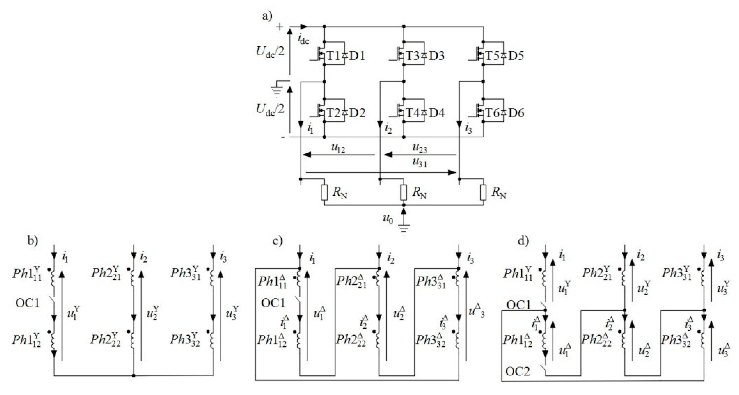
Figure 1. Diagram of (a) supply to brushless direct current (BLDC) motor, and configuration of windings in (b) star (Y), (c) delta (Δ), (d) combined star–delta (YΔ) configurations.
Energies 13 05321 g001
Figure 2. Physical model of the analysed BLDC motor design: (a) wound stator with terminals; (b) rotor.
Energies 13 05321 g002
Figure 3. Distribution of current densities and magnetic flux: (a) star; (b) delta; (c) star–delta configurations.
Energies 13 05321 g003
Figure 4. Stand for measurement of static characteristics.
Energies 13 05321 g004
Figure 5. Electromagnetic torque vs. rotor position: (a) numerical calculations; (b) measurements.
Energies 13 05321 g005
Figure 6. Waveforms of line-to-line BEMF.
Energies 13 05321 g006
Figure 7. Star (Y) configuration—waveforms of electromagnetic torque.
Energies 13 05321 g007
Figure 8. Star (Y) configuration—waveforms of line currents in healthy mode: (a) numerical calculations; (b) measurements.
Energies 13 05321 g008aEnergies 13 05321 g008b
Figure 9. Waveforms of line currents in the star configuration with open OC1 switch: (a) numerical calculations; (b) measurements.
Energies 13 05321 g009aEnergies 13 05321 g009b
Figure 10. Fast Fourier Transform (FFT) of neutral voltage u0 for star configuration in healthy mode: (a) numerical calculations; (b) measurements.
Energies 13 05321 g010
Figure 11. Star (Y)—FFT of neutral voltage star configurations of open circuits (OCs): (a) numerical calculations; (b) measurement.
Energies 13 05321 g011
Figure 12. Delta (Δ) configuration—waveforms of electromagnetic torque.
Energies 13 05321 g012
Figure 13. Delta (Δ) configuration—waveforms of line currents in healthy mode: (a) numerical calculations; (b) measurements.
Energies 13 05321 g013aEnergies 13 05321 g013b
Figure 14. Delta (Δ) configuration—waveforms of line currents with open OC1: (a) numerical calculations; (b) measurements.
Energies 13 05321 g014aEnergies 13 05321 g014b
Figure 15. Delta (Δ) configuration—FFT of neutral voltage u0 in healthy mode: (a) numerical calculations; (b) measurements.
Energies 13 05321 g015
Figure 16. Delta (Δ) configuration—FFT of neutral voltage u0 with open OC1: (a) numerical calculations; (b) measurements.
Energies 13 05321 g016
Figure 17. Star–delta (YΔ) configuration—waveforms of electromagnetic torque.
Energies 13 05321 g017
Figure 18. Star–delta (YΔ) configuration—waveforms of line currents in healthy mode: (a) numerical calculations; (b) measurements.
Energies 13 05321 g018aEnergies 13 05321 g018b
Figure 19. Star–delta (YΔ) configuration—waveforms of line currents in fault state OC1: (a) numerical calculations; (b) measurements.
Energies 13 05321 g019aEnergies 13 05321 g019b
Figure 20. Star–delta (YΔ) configuration—waveforms of line currents in fault state OC2: (a) numerical calculations; (b) measurements.
Energies 13 05321 g020aEnergies 13 05321 g020b
Figure 21. Star–delta (YΔ) configuration—FFT of neutral voltage u0 in healthy mode: (a) numerical calculations; (b) measurements.
Energies 13 05321 g021
Figure 22. Star–delta (YΔ) configuration—FFT of neutral voltage u0 in fault state OC1: (a) numerical calculations; (b) measurements.
Energies 13 05321 g022
Figure 23. Star–delta (YΔ) configuration—FFT of neutral voltage u0 in fault state OC2: (a) numerical calculations; (b) measurements.
Energies 13 05321 g023
Figure 24. Speed vs. load torque for Y, YΔ and Δ configurations: (a) healthy mode; (b) OC fault state.
Energies 13 05321 g024aEnergies 13 05321 g024b
Figure 25. Overall efficiency vs. load torque for Y, YΔ and Δ configurations: (a) healthy mode; (b) OC fault state.
Energies 13 05321 g025
Table 1. Torque constants for the analysed configurations.
YΔ
K T Y = 0.371 N·m/A K T Δ = 1 3 K T Y K T Y Δ = 2 3 K T Y
Table 2. BEMF constants for the analysed configurations.
YΔ
K E Y = 29.08 V/1000 r/min K E Δ = 16.8 V/1000 r/min K E Y Δ = 22.27 V/1000 r/min
K E Y = 100% K E Δ = 0.563   K E Y K E Y Δ = 0.766   K E Y
Table 3. Selected results for acceleration and noise level.
Configuration
/State of Work
SymmetryOC1OC2
Acoustic Noise [dB]Acceleration [m/s2]Acoustic Noise [dB]Acceleration [m/s2]Acoustic Noise [dB]Acceleration [m/s2]
Y1.264.66.872.1--
Δ1.264.41.164.3--
0.964.16.670.41.064.3