1. Introduction
According to the CIGRE C6.22 working group definition, microgrids are electrical distribution systems containing loads and distributed energy resources (DERs) like distributed generators (DGs) (renewable/nonrenewable), energy storage devices or controlled loads that can be operated in a controlled and coordinated way either while connected to the main power network or while islanded [
1]. Microgrids can be classified as either AC microgrids, DC microgrids or AC/DC hybrid microgrids, each having their own advantages, limitations and challenges, as described in [
2]. The technical challenges of AC microgrids can be broadly divided into two main categories: control challenges and protection challenges. The protection challenges can be further divided into two categories according to operational modes of the AC microgrid: grid-connected mode and islanded mode protection challenges.
When the AC microgrid is operated in the grid-connected mode, a large magnitude of fault current (ten times the full-load current or more) is available from the main grid in order to activate the overcurrent protection devices within the AC microgrid. When the AC microgrid is operated in the islanded mode, a very low magnitude of fault current is available from DGs within the AC microgrid, and hence, overcurrent devices with a single setting become insensitive. The consequences are the miscoordination of overcurrent devices, longer tripping delays and even no trips at all during different fault situations. The magnitude and duration of the fault current is mainly limited by the control of the converter-based DGs within the AC microgrid, which can be overcome by an additional fault-current source (FCS), like an energy storage device with high short-circuit capacity, and thus, single-setting overcurrent devices will become effective. However, the connection of an additional FCS will make the protection scheme unreliable due to dependence upon the single energy storage device. Moreover, the connection of many such FCSs will make the scheme quite expensive [
3]. Another alternative approach for using only single-setting overcurrent devices can be the limitation of the fault current from the main grid or directly coupled DGs using fault-current limiters (FCLs) in grid-connected mode and using lower fault-current trip settings, which can also work in islanded mode with reduced short-circuit currents. This approach causes overcurrent devices to be more sensitive in grid-connected mode and prone to nuisance tripping during transient events [
4]. The huge difference of the fault-current magnitude and duration in grid-connected and islanded mode calls for adaptive protection schemes for the AC microgrid.
The adaptive protection schemes can be only overcurrent-based [
5] or a combination of overcurrent-based and unit type (current differential) or based on other new protection methods like traveling waves-based [
3]. The adaptive overcurrent protection necessarily requires such overcurrent devices that provide the flexibility for changing the tripping settings like numerical overcurrent (OC) relays with several setting groups [
5]. The overcurrent schemes can be used more effectively in AC microgrids with the majority of directly coupled DGs (synchronous generators) compared with only the converter-based DGs, since the latter provide very limited fault currents for a very limited duration of time. Another reasonable adaptive approach is to use only the overcurrent protection scheme in the grid-connected mode and other protection schemes like directional overcurrent, harmonic content-based, voltage-based, symmetrical component-based, etc. in islanded mode for the AC microgrid with the converter-based DGs, with all functions included in a single protection device called the IED (intelligent electronic device). However, the protection schemes proposed for the islanded mode are not effective in every fault situation, and the majority of them need high-speed communication to remain effective [
4]. Finding a suitable and cost-effective combination of different effective protection schemes for the islanded mode with the converter-based DGs to work as primary and backup protection in a coordinated manner is still a huge challenge. An adaptive protection can be implemented either in a centralized manner by using a microgrid central controller to change the active-group settings [
5] or in a decentralized manner in which IEDs in the microgrid change their own active-settings groups by receiving a trip-signal/breaker status from another IED or circuit breaker. The centralized adaptive protection scheme necessarily requires a redundant microgrid central controller to maintain a certain level of reliability. For a decentralized adaptive protection scheme, the IEDs must be equipped with the required intelligent agents and logics in order to perform various functions in an autonomous manner using the available information (data/measurements/signals) both locally and remotely.
Previously, the adaptive protection for the AC microgrid using centralized protection and communication architecture was proposed in [
5,
6,
7]. An adaptive overcurrent protection for microgrids using inverse-time directional overcurrent relays (DOCRs) was presented in [
8]. In this paper, artificial neural networks (ANNs) at the central human machine interface (HMI) or data concentrator are implemented for the detection and location of the faults. The protection coordination of OC relays using the linear programming approach is presented for the radial and looped configurations of microgrids in both the grid-connected and islanded modes. An adaptive protection combined with machine learning for medium voltage (MV) microgrids was reported in [
9]. The proposed methodology requires a database available beforehand, which has been obtained through simulation in this research. Then, using the data mining methodology, the meaningful information is extracted quantitatively from the database. The ANN is used for fault detection and support vector machine (SVM) for fault location. The proposed method also requires relay settings calculations and recordings in the control center or relays beforehand. Moreover, the proposed scheme may generate inaccuracies in the case of data corruption, and therefore, additional countermeasures will be required. A new adaptive protection coordination scheme based on the Kohonen map or self-organizing map (SOM) clustering algorithm was proposed recently in [
10] for the inverse-time OC relays. In this paper, the protection coordination is improved gradually in the three phases of the proposed algorithm, namely conventional, clustering and sub-clustering phases. The proposed method uses digital OC relays with four setting groups. The performance of the method was presented in terms of the total miscoordination time (TMT) index using a modified IEEE 33-bus network with two synchronous generators and two electric vehicle (EV) charging stations. A decentralized adaptive protection scheme using DOCRs, teleprotection and a fuzzy system in real time was proposed in [
11] for the transmission system. In this paper, the transient stability constraint satisfying the maximum operating time of DOCRs was considered. Due to the dynamic adaption of the fuzzy system to the changing system conditions, the actuation time of relays was decreased, keeping the stability and coordination intact. An optimal overcurrent relay coordination in the presence of inverter-based wind farms and electrical energy storage devices was presented in [
12]. In this paper, the optimal protection coordination of inverse-time DOCRs with varying load demands and changing unit commitments of DGs is presented using mixed integer nonlinear programming. A hybrid particle swarm optimization-integer linear programming (PSO-ILP) algorithm was suggested recently in [
13] for the proper coordination of OC relays by suggesting proper settings groups for the changing network states. The adaptive differential protections for wind farm-integrated networks were reported in [
14,
15]. However, the differential protection inherently cannot provide the backup protection, and usually, the time-coordinated overcurrent protection is used as the backup protection.
The modeling of the inter-substation communication based on the IEC 61850 standard was presented in [
16] for the differential protection (Sampled Values (SV) messages) and in [
17] for the distance protection (generic object-oriented substation event (GOOSE) messages). In both [
16] and [
17], the virtual simulated communication networks were used based on a non-real-time tool called the riverbed modeler network software. In both references [
16] and [
17], the tunneling communication mechanism between substations was used for the differential and the distance protection functions, respectively. In [
16], it was evaluated that the dedicated fiber optic network link had better performance in terms of the end-to-end delay of SV and GOOSE messages compared with an asynchronous transfer mode (ATM) link and synchronous optical networking (SONET) links. It was concluded in [
17] that the links with lower bandwidths were not suitable for long distances; however, a more accelerated distance protection can be implemented, even with lower bandwidth links, compared with the conventional distance protection scheme. An adaptive protection system based on the IEC 61850 for MV smart grids was presented in [
18]. In this paper, the dynamic publisher/subscriber reconfiguration of the protection devices for the implementation of the advanced fault location, isolation and service restoration (FLISR) was suggested. Since, the remote changes of the IED settings are not supported by the current versions of the IEC 61850 standard, therefore, the change of the operational settings after the network reconfiguration was suggested using the exchange of MMS (manufacturing message specification) messages with IEDs. Additionally, the logic selectivity was proposed to support remote changes of GOOSE communication schema without interrupting the FLISR operation. A mixed-layer 2/3 approach was also suggested in the paper to support both the MMS and the GOOSE implementations for the field demo of an Italian MV network. A detailed survey of different adaptive protections of microgrids was presented recently in [
19]. For a further detailed review of different microgrid protection schemes, their challenges and developments, the recent review articles [
20,
21,
22,
23] are suggested, in addition to the previous review article [
4] by the authors. For further information related to IEC 61850-based substation automation systems and related issues, the recent literature survey done in [
24] is also recommended.
Based on the recent literature review presented above, it was found that less literature is available for the role of IEC 61850 standard-based communication in the protection coordination of the AC microgrids with decentralized protection and communication architecture. Moreover, a low-voltage ride through (LVRT) capability with reactive power support from the converter-based DGs in the case of AC microgrid faults has rarely been used for adaptive protection. The high risks of communication link failures and unacceptable and unpredictable communication delays are still the limiting factors to use communication links for high-speed protection functions. However, the use of a communication link is inevitable for protection functions like transfer trips from the breaker/IED at the point of common coupling (PCC) to another breaker/IED within the AC microgrid for loss of mains detection and changing preplanned active-groups settings/functions during the transition from the grid-connected to island mode for deactivating sensitive anti-islanding protection during faults and for reverse interlocking schemes. In this paper, the main focus is to discuss how an IEC 61850 communication can be applied for a decentralized preplanned adaptive overcurrent protection in a radial AC microgrid. Additionally, the DGs with LVRT capability and reactive power support in islanded mode are considered in order to implement the adaptive overcurrent protection.
The rest of the paper is organized in a manner that
Section 2 presents adaptive protection based on the IEC 61850 communication standard by explaining a generalized architecture of the adaptive AC microgrid.
Section 3 gives a case study background of the adaptive protection of a radial AC microgrid, explaining GOOSE (generic object-oriented substation event) message delays (transfer time) for IED to IED communication for different functions, the schematic diagram of radial the AC microgrid and adaptive protection settings of different IEDs.
Section 4 explains the details of the proposed adaptive protection methods and results for both the grid-connected and islanded modes of operation. Additionally, the control of DGs and the LVRT capability of DGs are also explained in this section.
Section 5 gives a brief discussion about the previous methods, the contribution of the research presented in this paper and what is needed for the practical implementation of the proposed method in the future.
Section 6 provides the conclusion of the paper.
2. Adaptive Protection Based on IEC 61850 Communication Standard
An adaptive protection is necessarily required for AC microgrids due to changing operational modes (grid-connected and islanded), due to the formation of controlled islands due to faults within the AC microgrid, due to intermittent DGs and periodic load variations and due to the economical operations of the AC microgrid [
4,
25]. An adaptive protection is defined as an online activity that changes to the preferable protection device response for modified system conditions or requirements. An adaptive protection is normally automated, but some timely human interventions may also be included. Adaptive relay is a relay that includes various settings, characteristics or logic functions capable of speedy online modifications by means of externally generated signals or control actions [
26]. The modern intelligent electronic devices (IEDs) not only provide various protection functions (overcurrent, over/under voltage, etc.) integrated in a single physical device but, also, offer various setting groups for each of the available protection functions. The various setting groups of the protection functions can be modified or altered in an adaptive manner using the communication link between IEDs and IEDs and circuit breakers (CBs). Recently, the popularity of the IEC 61850 communication standard for application in electric power substation automation has increased considerably due to its promise of interoperations among IEDs from different manufacturers. The initial focus of the standard is on communication between IEDs within a single substation, but its extension for communication between several substations in the future is possible. The IEC 61850 standard explains the standardized structures for the data model and definitions of rules for the exchange of these data. IEDs from different manufacturers that comply with these standard data model definitions can then communicate, understand and interact with each other [
26]. The IEC 61850 standard as a common protocol enables the integration of all protection, control, measurement and monitoring functions [
27].
The generalized architecture for adaptive AC microgrid protection based on the IEC 61850 communication standard is depicted in
Figure 1. The IEC 61850 communication architecture for adaptive AC microgrid protection can be subdivided into three levels: process level, bay level and substation level. At the process level, the electrical parameters measurement data (MMXU) from the voltage and current sensors (VTs and CTs) and status of the circuit breakers (XCBR) inside the AC microgrid will be collected and digitized by merging units (MUs). At the bay level, the IEDs for lines, DGs and loads of the AC microgrid will collect the digitized measurement data (MMXU) and circuit breaker status signals (XCBR) from the process bus. Each MU will publish data to process the bus, and each IED will subscribe to the respective published data from the process bus. Each of the line, DG and load IED will use measurement data (MMXU) from their respective MU for performing the active protection function like overcurrent protection in the case of faults. The status signal of the circuit breakers inside the AC microgrid (XCBR) will be used by each adaptive IED to change the active setting groups of the protection function in the case of a fault inside the AC microgrid in islanded mode. Moreover, a XCBR signal can also be used for the transfer trip of nonadaptive IEDs that are unable to detect the faults within the islanded AC microgrid. All IEDs at the bay level will also receive the status signal (XCBR_pcc) from the circuit breaker at the point of common coupling through the station bus at the substation level. The status signal from the PCC breaker (XCBR_pcc) will be used by each adaptive IED within the AC microgrid to change the active setting group of the protection function from grid-connected mode settings to islanded-mode settings and vice versa. The signal (XCBR_pcc) can also be used for the detection of the loss-of-mains event by DG IEDs and to deactivate the sensitive loss-of-mains protection functions in order to maintain stability and reliability of supply within the AC microgrid during the transition from the grid-connected to islanded mode. The station bus at the substation level will provide primary communication between the various logical nodes of IEDs. In other words, all IEDs at the bay level will communicate and share data/information (MMXU, XCBR, and XCBR_pcc) with each other using the station bus. At the station bus, a remote access point will also exist to share data with remote clients (for wide-area measurement and protection, etc.) through a wide-area network (WAN). This remote access point will implement security functions like data encryption and authentication for all data transfers and, thus, will unburden the individual IEDs to perform these tasks.
For an adaptive OC protection, the coordination between the control and protection of the AC microgrid will also be required, and control action will be required first, followed by protection action. In the grid-connected mode, a high fault current from the grid will be available, so depending on the protection settings of IEDs, it may be required to limit the magnitude of the fault current by the activation of FCLs, and in the islanded-mode with converter-based DGs, the enhancement of the fault current magnitude may be required by the activation of additional FCSs. The numerical results presented in [
28] indicate that a majority of the photovoltaic (PV) inverters contribute a fault current of 200% or less for a duration of only an initial half-cycle and 110% of the rated current for an additional duration of 10 cycles or less. It is mentioned in [
29] that the grid-connected converters can feed fault currents of 1.1–1.5 p.u. of their nominal currents. It should here be noted that extra FCSs like batteries, flywheels or supercapacitors with quick response times (≤10 ms) [
30] will either be necessarily required to support some type of DGs like photovoltaic DGs for providing standard LVRT capability or extending the LVRT duration of other types of DGs like wind turbine generators (WTGs) for proper protection coordination if the WTG is not capable of providing LVRT. The results presented in [
31] show that a wind turbine of 1 MW can provide a fault current of magnitude equal to 120% of the rated current for seven cycles of supply frequency. This duration of seven cycles with a 50-Hz supply frequency is approximately equal to the initial duration of 150 ms after fault in the LVRT characteristic of the German BDEW-2008 standard [
32]. Although the duration of 150 ms looks sufficient for the maintenance of proper protection coordination between two successive IEDs within the AC microgrid, assuming high speed communication with 3–10-ms one-way fast trip message transfer as per the IEC 61850 standard and high-speed circuit breakers (one-cycle operation). However, in some cases like data loss in the transmission channel, the retransmission of the message is required, which will result in an additional delay. Moreover, the coordination between various IEDs for breaker failure protection may be required. In such situations, the extension of the initial duration after the fault in the LVRT curve beyond 150 ms will be required, and hence, additional FCSs (flywheels or supercapacitors) will be required. In addition to that, a redundant communication and redundant synchronization clock architecture will be required to cover the communication link and synchronization clock failures as recommended in [
33].
In this paper, the main focus was given to the adaptive OC protection using fault contributions from DGs with LVRT capability, particularly in the islanded mode of the AC microgrid. Hence, the control of DGs is not discussed in detail, except a few control actions for maintaining the voltage and frequency at the islanded sections, as explained in
Section 4. Moreover, the loads and generation are considered balanced in islanded mode of the AC microgrid. The same is true even for the islanded MV and LV (low voltage) sections of the AC microgrid. The paper is limited to single fault events (three-phase short-circuit faults only) during the grid-connected and islanded modes with smooth transitions to islands. However, the method presented can be extended to other types of faults. In this paper, it is not considered how the islanded AC microgrid is reconnected back to the main grid after the removal of the fault events, which is mainly related to resynchronization procedures and not directly related to AC microgrid protection. Considering the previous research, the fault contributions from DGs (both PV and WTG) are taken as 1.2 p.u. or 120% of their rated nominal currents for a duration of 150 ms after the fault. During the initial fault duration of 150 ms, the active, passive and other islanding detection and protection schemes are considered normally interlocked and can be activated quickly after the loss of communication. This means that the anti-islanding protections like under-voltage protection at DG locations can be set by default to only detect fault conditions but not trip, and DGs start providing fault currents instantaneously according to the LVRT characteristics. The trip-blocking signal to anti-islanding protection can be sent additionally from an IED at PCC after a fault is detected on the main grid side; it should be done as fast as possible and within 3 ms after fault detection, as per the IEC 61850 standard. In this paper, the term “adaptive IED” mainly refers to the communication-assisted definite time overcurrent (DTOC) relay with two preplanned setting groups: higher setting group for the grid-connected mode and lower setting group for the islanded mode of operation. The case study of a typical radial AC microgrid equipped with adaptive DTOC relays and DGs with LVRT capability is presented in the next section.
3. Case Study
An IED-to-IED GOOSE message exchange within a substation is required for fast bus tripping in the case of bus faults and the interlocking of bus-IED in the case of feeder/line faults, the protection scheme traditionally known as the reverse interlocking scheme. The IED-to-IED GOOSE messages can also be used in the case of breaker failure to trip the adjacent breaker(s). This can be done by sending a trip command message to adjacent breakers from a protection IED with a built-in breaker failure function or from a dedicated IED performing only the breaker failure function. The transfer trip may also be required between two substations. The transfer time requirement of 10 ms was set in IEC 61850 for fast trip messages (releases and status changes) between substations (transfer time class TT5) and 3 ms for fast trips and blocking messages between IEDs within a substation (transfer time class TT6) [
33,
34]. The transfer time requirement also varies with respect to the specific protection function. The transfer times required for various protection functions are given
Table 1.
Although very strict time requirements have been demanded in IEC 61850 for type 1A fast trip messages, in this study, an average transfer time of 10–20 ms was considered for the one-way GOOSE message to cover the limitations (the limited failures of LAN within a maximum allowed transfer time of 18 ms), safety margins (errors in the time-stamp accuracy) and redundant GOOSE messages for communication between substations, as explained in [
35]. IEC 61850-90-1 [
36] recommends a maximum time delay of 5 to 10 ms on the communication channel depending on the voltage level [
37]. However, in order to meet the requirements of security, reliability and dependability according to the IEC 60834 standard, the communication system should meet the 3-ms transfer time requirement for 99.9999 percent of the time and should have a delay no longer than 18 ms for the remainder of the time [
38]. A fixed transfer time of 20 ms is thus used for both IED-to-IED communication within a substation and IED-to-IED communication between different substations in this study to cover even the worst time delay of 18 ms for the type 1A messages. In practical cases, generally, the transfer time for communication between IEDs at different substations is longer than the transfer time within the same substation. Measuring the one-way communication latency by a round-trip time between two remote substations was discussed in [
39]. The selected one-way transfer time of 20 ms for producing results corresponded to the fast messages of type 1B (the ideal case) with performance class P2/P3 (transfer time class TT4) [
33,
35], and it covers the worst-case delay of 18 ms of type 1A fast messages according to the IEC 60834 mentioned above. The considered transfer time was also within the range of practical observed time delays in the light-weight implementation of the IEC 61850 standard-based GOOSE messages done in [
40]. Although GOOSE messages apply the heartbeat messages and an IED will issue a so-called burst of GOOSE messages right after the detection of the fault, for the final trip decision, the IED necessarily needs to know the updated status at the downstream IED after the fault to ensure proper coordination. The selected 20-ms communication delay between IEDs ensures that even the type 1A GOOSE messages with the maximum delay of 18 ms are also subscribed by IED for the trip decision. Another reason of selecting a 20-ms delay between IEDs is the potential requirement to use GOOSE messages to transfer analog data between IEDs for trip decision criterion like vectors of measured values (RMS values), which need to be transmitted only once per cycle of 50-Hz frequency. It means a new analog measurement data is required to be transmitted in just every 20 ms [
37]. In the earlier publication [
33], it was mentioned that there were two types of GSE (generic substation event) messages: GSSE (generic substation state event) message and GOOSE message. The GSSE message is the old binary-only message type. All the modern systems use the more flexible GOOSE message, which transfers both binary and analog data. Both GSSE and GOOSE can coexist but are not compatible with each other. The proposed protection algorithm in this paper not only uses the binary data but, also, uses the analog data (RMS magnitude of currents) for the trip decision.
In this paper, the conventional GOOSE (tunneled-GOOSE) messages in layer 2 (horizontal communication) with an Ethernet link are considered, because the short distances (a few km) between substations are considered. However, for the longer distances between substations where an Ethernet link is not possible, the routable-GOOSE (R-GOOSE) messages in layer 3 (vertical communication) for wide-area or system protection applications could be used, especially with wireless communication technologies using synchrophasors in compliance with IEC TR 61850-90-5. Some applications of R-GOOSE were reported in [
41]. The normal predefined fixed GOOSE message transfer delay of 40 ms (2 cycles of 50-Hz power system) was assumed previously for the adaptive protection of the microgrid using communication over a WiMAX network in [
42], and the actual latency observed was within 35 ms with no data packet loss. However, due to packet loss and, consequently, retransmissions, the overall delay could further increase, thus limiting the application of WiMAX (R-GOOSE) to comparatively slower control and protection actions like status updates and protection settings during scheduled maintenance and load management. The adaptive protection methodology presented in this paper is concerned with primary and backup protections of the microgrid during faults in predefined operational modes: grid-connected or islanded modes. With this regard, a communication-dependent coordination methodology is proposed in
Section 4 for the cases when the fault happens between two defined IEDs in grid-connected and islanded modes. The proposed methodology is very generic in nature and can be implemented in any protection IED.
The schematic diagram of a radial AC microgrid under study is shown in
Figure 2. The considered AC microgrid consists of one MV bus of 20 kV (Substation Bus-2) and one LV bus of 0.4 kV (Substation Bus-3). A load of 2 MW at Substation Bus-2 is supplied by a wind turbine generator (WTG) of 2-MVA capacity, whereas a load of 0.4 MW at Substation Bus-3 is supplied by a photovoltaic (PV) generator of 0.4 MVA. The MV bus (Substation Bus-2) of the AC microgrid is connected with the LV bus (Substation Bus-3) of the AC microgrid through a 1-km-long, 20-kV cable line and 0.5-MVA, 20/0.4-kV transformer. The AC microgrid is connected with the main grid through a 2-km-long, 20-kV overhead line and an intermediate 20-kV Substation Bus-1. The WTG is connected to Substation Bus-2 through a 0.2-km-long 20-kV cable and a 2-MVA, 0.69/20-kV transformer (inside the WTG model). A 2-km overhead line between Substation Bus-1 and Substation Bus-2 is protected by two circuit breakers, CB1 and CB2, with the related protection IEDs. The protection IED1 is considered to be a nonadaptive IED due to its direct connection with the main grid, whereas the protection IED2 is considered as an adaptive IED. In the grid-connected mode, IED2 operates with settings that enable the tripping of CB2 in the case of bus fault F8 at Substation Bus-2 and facilitates the transfer trips of CB2 after receiving the CB1 open-state signal in the case of short-circuit fault F1. However, if IED2 fails to receive a CB1 open-state signal in the case of short-circuit fault F1 after the opening of CB1 and the AC microgrid already changed to islanded mode with a trip-block signal to all IEDs, this will be the failure of the transfer trip. In this case IED2 can provide a backup operation by opening CB2 with the fault current still coming from the DGs within the AC microgrid. This can be performed by IED2 either with the islanded mode settings or using the current magnitude comparison and the direct transfer trip failure logic, as explained later in
Section 4. The IED2 may take quite some time to change its active group settings from the grid-connected mode settings to the islanded mode settings, and this will require DGs to remain online for additional time beyond the standard LVRT curve until the IED2 settings are changed and the tripping of CB2 is executed. However, the backup operation of CB2 by the direct transfer trip failure logic implemented at IED2 could be performed within the standard LVRT curve. In the islanded mode, the IED2 settings are adapted so that the fault F1 is detected when the CB1 is open. The 1-km cable line between Substation Bus-2 and Substation Bus-3 is protected by CB6 and CB7 with the related protection IEDs. The protection IED6 and IED7 are also considered to be adaptive.
The adaptive IED6 primarily protects both the cable line and the 20/0.4-kV transformer from short-circuit fault F2 during both the grid-connected and islanded mode of operations. In the islanded mode, after sensing the fault current at its location, the adaptive IED6 trips CB6 and transfer trips circuit breaker CB7. Additionally, IED6 and IED7 can compare the post-fault magnitude of currents at their locations with a 1.2-p.u. threshold and determine the location and direction of the fault between IED6 and IED7, as explained in the coming section. The adaptive IED7 can also provide backup protection in case of transfer trip failure (like the adaptive IED2 does, as explained earlier) in the case of the fault F2 in the grid-connected mode, in addition to the normal protection against bus fault F4 at Substation Bus-3 in both the grid-connected and islanded modes by direct tripping CB7 and transfer tripping CB9. The IED7 can only provide an “adaptive trip” to CB7 for the transfer trip failure from IED6 in the case of short-circuit fault F2 in the grid-connected mode if sufficient fault current contribution from PV is available beyond the standard LVRT characteristic curve. This is because the IED7 may need quite some time to change its active group settings from the grid-connected mode settings to the islanded mode settings, and PV must remain online until IED7 settings are changed and CB7 tripping is executed. For this purpose, a new LVRT curve proposed later in this paper can be used. The 0.2-km cable connecting WTG with Substation Bus-2 is protected by CB3 with an adaptive IED3. Both MV and LV loads are also provided with adaptive IEDs (IED5 and IED8), which trip CB5 and CB8 adaptively in the case of load-side short-circuit faults F3 and F9 in both grid-connected and islanded modes of the AC microgrid.
The adaptive IEDs with two preplanned setting groups for AC microgrid lines are provided with only under-voltage (UV) local backup protection (
Figure 3a) and adaptive IEDs with two preplanned setting groups for loads with both under and over-voltage (UV/OV) backup protection (
Figure 3b). The DG protection IEDs (IED4 and IED9) are also considered to be adaptive in order to differentiate between the grid-connected and islanded mode operations. Moreover, DG protection IEDs should not trip instantaneously in the case of all external faults and allow DGs to provide fault current contributions according to predefined standard LVRT characteristics. A multifunctional adaptive IED for the protection of converter-based DGs is shown in
Figure 4, which consists of adaptive OC and anti-islanding protection functions. In practice, DGs may be provided with unit protection and IEDs with several fault protection and anti-islanding protection functions. In this study, the anti-islanding protection functions (passive/active methods) of DG protection IEDs are assumed normally “disabled” if the communication link is continuous and enabled quickly when the communication link is lost. Thus, communication-based loss-of-mains detection with no nondetection zone can be used as a primary means of anti-islanding protection and passive/active methods as backup in the case of communication link failure. All the sensitive protections within the islanded AC microgrid need to be disabled/interlocked during the starting of DGs, motor loads and during the transient period when changing from the grid-connected to islanded mode and vice versa.
4. Adaptive Protection Methods and Results
Although several faults may happen in the presented AC microgrid, only adaptive protection methods and results of three-phase ungrounded short circuit faults with 0.01-Ohm fault resistance at locations F1 and F2 are presented. Moreover, for the sake of simplicity, it is assumed that three-phase fault F2 occurs only in the islanded mode. Nevertheless, the adaptive protection method for fault F2 also considers the protection option in the case of F2 in the grid-connected mode, as explained in the following text.
Figure 5 shows the flowchart of communication-based nonadaptive IED1 for protection during fault F1. IED1 provides primary protection for fault F1 and the backup protection with definite time delay for all other downstream faults using OC relay and UV protection works as backup of the OC relay. The IED1 normally uses the redundant communication link to get information about downstream faults and use this information for trip decisions. If the fault is downstream, it waits for the CB2 to trip first. On receiving a CB2 failure signal, it trips CB1 and sends a CB1 status “open” GOOSE message (XCBR signal) to all IEDs to change their settings to the islanded mode. Even if CB1 fails, it can transfer the trip incoming breaker CB0 of substation-1 to initiate the islanding. If no communication link is available, IED1 will simply trip CB1 using definite time delays depending on the magnitude of the current.
Figure 6 shows the steps for the clearance of fault F1 using GOOSE messages with different transmission delays. In both cases, at step 7, IED2 can be used in an adaptive manner for tripping CB2 to clear F1 completely, if not directly tripped by the CB1 status transfer trip, as mentioned in step 7 of
Figure 6. If CB2 is not tripped with the CB1 status transfer trip or the adaptive trip by IED2, then fault F1 will not clear due to fault energization by DGs in the AC microgrid, and DGs will trip after LVRT time is elapsed.
Figure 7 shows the flowchart for the clearance of fault F2 in both grid-connected and islanded modes by adaptive IED6 by tripping CB6 and sending trip signal XCBR “open” to IED7 for tripping CB7. With CB6 and CB7 open, two separate islands were created within the islanded AC microgrid, one supplied by only PV (LV microgrid) and other supplied by only WTG (MV microgrid). If fault F2 occurs in the grid-connected mode, then only the LV microgrid will be isolated, and the MV microgrid will operate in the grid-connected mode. IED7 will also need the current flow direction in the case of fault F2, since this fault will be energized by both PV and WTG in islanded mode, which will avoid nuisance tripping by IED6 in the case of bus-3 fault or fault F3 at the LV load. IED7 can easily know if the fault is upstream or downstream of its location after receiving “YES fault GOOSE” from IED6 by simply calculating the RMS magnitude of the current at its location. If the magnitude of current at IED7 is ≤1.2 p.u. of the normal set current, the fault is considered to be upstream of IED7, since the fault contribution at IED7 will come from downstream PV only. In this case, IED7 will send “NO fault GOOSE” to IED6. If the magnitude of the current at IED7 is >1.2 p.u. of the normal set current, the fault is considered to be downstream of IED7. In this case, IED7 will send “YES fault GOOSE” to IED6, and IED6 will wait until the next GOOSE from IED7. The red and green colors in
Figure 7 differentiate between the grid-connected and islanded mode features. On the failure of CB6, IED6 will trip CB2, CB3 and CB7 to clear F2 in the grid connected mode, whereas CB7 and CB3 will be tripped in the islanded mode to clear fault F2 completely. Hence, CB6 failure during fault F2 in both grid-connected and islanded modes will cause complete power interruptions to MV microgrid loads.
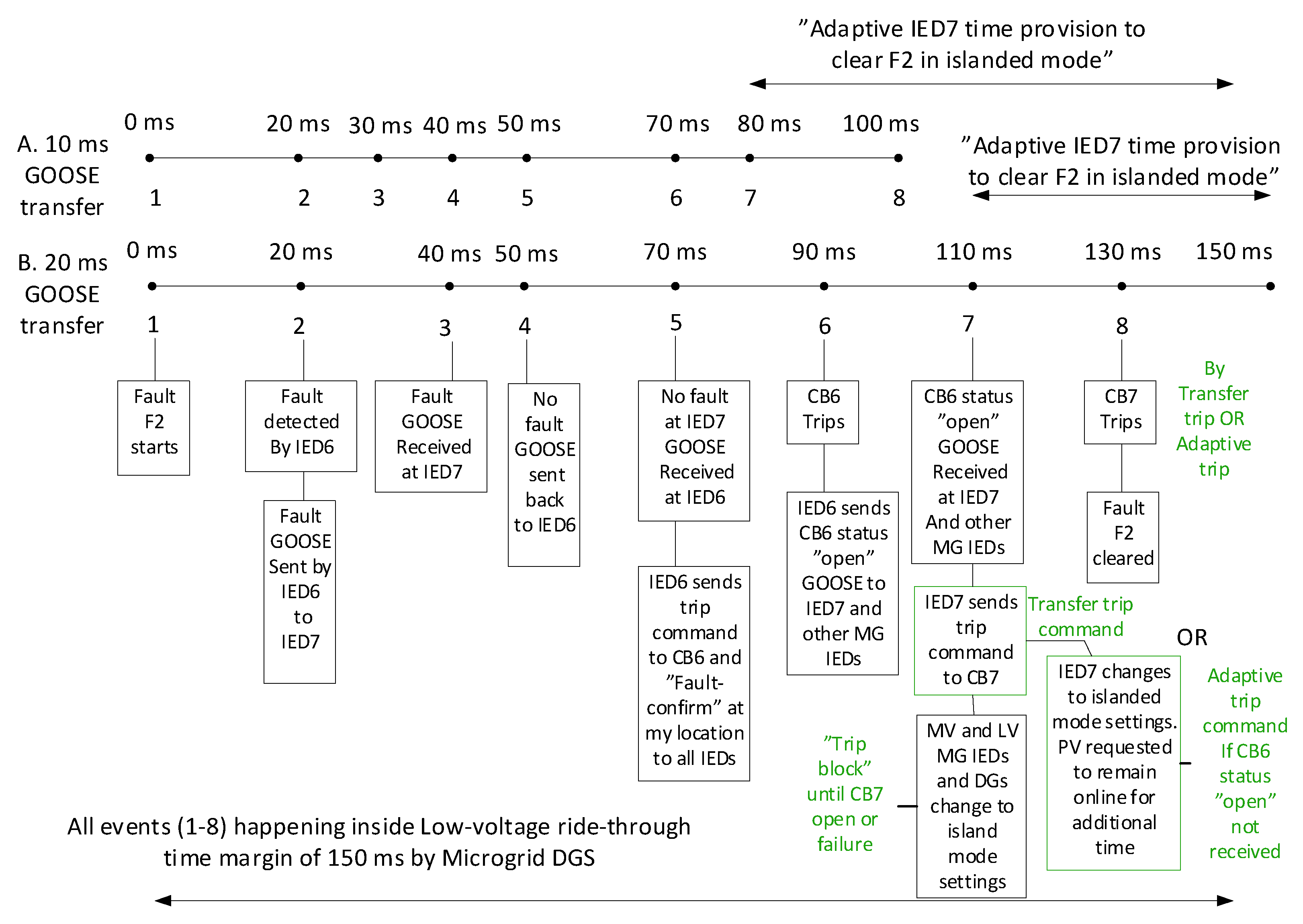
Figure 8 shows the steps for the clearance of fault F2 using GOOSE messages with different transmission delays. It should be noted that, in steps 5 and 6 and 7 and 8 of
Figure 6 and
Figure 8, the time delay for circuit breaker operation is considered 20 ms, which is one cycle of 50-Hz supply. This means high-speed AC circuit breakers operating in one cycle [
43] will be required for the implementation of the proposed adaptive OC protection scheme.
Table 2 shows the normal flow of currents measured at the IED1, IED2, IED6 and IED7 locations during four different DG scenarios in the grid-connected mode. The maximum currents used for the adaptive DTOC settings are also indicated in
Table 2. The fault current magnitudes at the concerned IEDs during the short-circuit fault F1 in the grid-connected mode and the short-circuit fault F2 in the islanded mode are shown in
Table 3.
Table 4 shows the DTOC settings and time grading of the IEDs 1, 2, 6 and 7 in the grid-connected and islanded modes. In this study, only the high-stage setting group (I>>) of
Table 4 was used for the detection of the three-phase short circuit faults, and the isolation of the fault (tripping) is totally dependent on the GOOSE message transfer, according to
Figure 6 and
Figure 8. However, in the case of complete communication failure, the time grading of
Table 4 ensures selective operation.
Table 5 explains the adaptivity and current magnitude comparison (CMC) requirements at IEDs of
Figure 2 for three-phase faults (F1–F9) at different locations in different modes of operation. In the grid-connected mode, the higher setting group like that given in column two of
Table 4 will be applied for all IEDs irrespective of the connection and disconnection status of DGs. This higher setting group is denoted by SG
GM in
Table 5 to represent the active settings in the grid-connected mode. For all IEDs except IED1, IED5 and IED8, a separate local current magnitude comparison function/logic is proposed for the operation in both the grid-connected and islanded modes when DGs are actively participating in load sharing with the connection status “YES”. The CMC function in the IEDs will logically work in parallel with the communication-based DTOC protection and would act quickly with the “transfer trip communication failure” signal to trip the local downstream IED during the upstream fault if it does not receive the transfer trip signal (CB status “OPEN”) from the upstream IED after a predefined time period (time period between step 6 and 7 in
Figure 6). The CMC function will continuously receive the analog value of the current from the local MU and compare it with the current threshold of 1.2 p.u. of the max current; if the current is less than the threshold and the upstream IED also sends a fault detection GOOSE “YES”, the fault is assumed to be the upstream fault. Then, if no transfer trip GOOSE is received from the upstream IED within 110 ms of the fault (event 7 in
Figure 6), the IED will trip the local circuit breaker to clear the fault completely. In this way, the CMC function implemented in the communication-based adaptive protection (
Figure 7) could not only detect the direction of the fault, but it could also act as a backup for direct transfer trip (DTT) communication failure. The proposed CMC function can only work for the feeder with a strong DG source on one side and a comparatively weaker DG source with a predefined fault current contribution on the other side. For example, during the fault F1 in the grid-connected mode when the connection status of both the WTG and PV is “YES”, the IED2-IED4, IED6-IED7 and IED9 all will need the CMC function to determine if the fault is at the downstream or the upstream location. However, only IED2 will activate the CMC trip function after the transfer trip GOOSE message from IED1 is found undetected (not received). In the same way, during the fault F2 in the islanded mode of operation when the connection status of both the WTG and PV is “YES”, the IED6-IED7 and IED9 need the CMC function to know if the fault is upstream or downstream of these relays. IED6 using the CMC function will detect the fault F2 to be downstream, while IED7 and IED9 will detect the fault to be upstream of their locations. Then, when the transfer trip GOOSE from IED6 is not received by the IED7, it will initiate the backup using CMC logic to trip CB7 in order to clear the fault F2 completely, while IED9 will continue following the LVRT curve. The topmost AND logic in
Figure 9a,b presents the backup for DTT failure from IED6 during the fault F2 using the CMC function/logic. It should be noted that, in the islanded mode, when the connection status of both the WTG and PV is “YES”(the scenario of
Table 5, column 3), then the WTG of 2 MW acts as a comparatively stronger source than the PV of 0.4 MW. Therefore, the grid-connected mode settings “SG
GM” for IED6-IED9 will remain effective and unchanged in this islanded mode scenario, and only IED3-IED5 need to change to the islanded mode settings (SG
IM). This way, the minimum number of IEDs will need to adapt to the islanded mode settings, and simple logics for the primary and backup protections, for example, at IED7 (
Figure 9a), could be used. This will also prevent the OC function of IED7 and IED9 to start pickup for the “out of zone” fault F2 in the islanded mode scenario of
Table 5, column 3.
If, during the islanded mode (
Table 5, column 3 mode), the settings of IED6, IED7 and IED9 are changed to the islanded mode settings (SG
IM), then OC function of all the three IEDs will start picking up not only during the downward fault F5 but, also, during the upward faults F4 and F2. Hence, the protection logic for the detection of the “in-zone” fault direction and location will become more complex with the islanded mode settings (
Figure 9b) compared with the protection logic with the grid-connected mode settings (
Figure 9a). The bottom AND logic of
Figure 9a represents the protection logic of IED7 with the grid-connected mode settings (SG
GM) for “in-zone” fault F4, where only “NO fault” detection signals at downward IED8 and IED9 are sufficient to activate the primary and time-delayed backup protection at IED7, in addition to the local IED7 and upward IED6 “fault YES” signals and the CMC function outputs for “downward” fault. The bottom AND logic (black) of
Figure 9b represents the protection logic of IED7 with the islanded mode settings (SG
IM) for the “in-zone” fault F4, where not only “NO fault” detection at downward IED8 and IED9 are required, but also, the CMC function output at IED9 for “upward” and “downward” faults will also be required to activate the primary and time-delayed backup protection at IED7, respectively, in addition to the local IED7 and upward IED6 “fault YES” signals and the CMC function outputs for the “downward” fault. The protection logics presented in
Figure 9 will be necessary in order to quickly detect the fault and isolate the faulty section within 150 ms, keeping the stability of the remaining system intact if the communication system performance is according to the predefined boundaries. In the case of communication failure, the normal communicationless time coordination described in
Table 4 will be applied.
4.1. Results for Fault F1 in Grid-Connected Mode and Transition to Islanded Mode
For three-phase fault F1, the adaptive OC relay logics are implemented in PSCAD (Power Systems Computer Aided Design) simulation software according to
Figure 6 and settings according to
Figure 3 and
Table 4. The fault starts at 1.2 s and ends at 5 s; this fault duration is small, but it is assumed to be a permanent fault. The fault current magnitude at IED1 and IED2 before and after the fault F1 is shown in
Figure 10. It shows that fault current magnitude is enough at IED1 location and can be detected easily with higher OC settings (SG
GM). However, the fault current magnitude at IED2 is not enough to detect the fault with its higher settings, since at IED2, the fault contribution mainly comes from DGs, which are set to provide a fault current up to 1.2 p.u. of rated DG current. Hence, to remove fault F1 completely, either CB2 should be remotely direct transfer-tripped by IED1 using “CB1statusOpen” signal communication or IED2 should adapt to lower settings (SG
IM) and issue an “adaptive trip” command to CB2 if “CB1statusOpen” is not received at IED2 within the predefined delay.
Figure 11 shows the tripping of CB1 at about 1.29 s with a delay of 90 ms after the fault at 1.2 s and CB2 tripping at 1.334 s with a delay of about 134 ms after the fault at 1.2 s, as per method-B steps 6-8 in
Figure 6; in this case, CB2 is successfully transfer-tripped.
Figure 12 shows the RMS magnitude of the current of DGs before, during and after the fault F1 with the successful CB2 transfer trip method.
Figure 13 shows the detection of fault F1 by lower settings of adaptive IED2 in islanded mode (CB1 already open, and transfer trip from IED1 to IED2 failed) and subsequent tripping of CB2 to clear F1 completely. The CB1 is tripped at 1.29 s according to method-B step 6 in
Figure 6, and IED1 sends the circuit breaker status “Open” to all IEDs within next 20 ms. The DGs and IEDs except IED2 within the islanded AC microgrid receive the circuit breaker status “Open” from IED1 and change their mode/settings at 1.31 s; all IEDs (except IED2) remain in a “trip block” state until a “CB2 open” or “CB2 breaker failure” signal from IED2 is received. Meanwhile, an adaptive IED2 changes to lower settings due to transfer trip failure; it detects the fault, sends an “adaptive trip” command to CB2 at 1.345 s and CB2 finally trips at 1.37s. On receiving the “CB2 open” signal, all IEDs within the AC microgrid may issue “block release” to their CBs after the terminal voltage of DGs will reach a value >50% of its normal value. This will ensure no IED tripping during transition to the normal islanded mode, because DGs will continue LVRT and fault contribution until 50% terminal voltage is reached after the fault clearance recovery.
Figure 14 shows the RMS magnitude of the current of DGs before, during and after the fault F1 with an adaptive IED2 trip. The results in
Figure 13 show that it takes 20 ms more than the required 150 ms time for clearance of the fault with adaptive IED2 settings. This is because the DG output current takes an extra 10 ms to stabilize and reach the threshold setting of adaptive IED2. Moreover, both IED2 and CB2 take 5 ms more than the set time of 20 ms for fault detection and tripping.
Figure 13 also shows that it will take 15 ms extra for DGs to restore to normal operations (normal currents) in the islanded AC microgrid after the removal of fault F2 completely at 1.37 s. These types of extra delays highlight the demand of faster communication with less than 20 ms one-way transfer delay or extension of the initial time after the fault inception in the LVRT characteristic curve for effective adaptive protection in order to maintain the supply in islanded mode. Otherwise, it will cause the complete loss of DGs within the AC microgrid during fault F1 due to the tripping by anti-islanding (e.g., UV) protection at 150 ms after the fault. This, of course, will decrease the reliability of supply for AC microgrid loads due to extra time for the black start of DGs in the islanded mode, then removal of fault F1 by adaptive IED2 and, finally, the restoration of the normal load. In the presented cases by using a 20-ms delay of one-way GOOSE transfer for the complete removal of fault F1, the transfer trip method is faster than using adaptive IED2 tripping in the islanded mode: a direct transfer trip takes about 150 ms after the fault, and the second backup procedure (adaptive tripping) takes about 190 ms after the fault. However, if the delay of 10 ms for one-way GOOSE transfer is used (Method-A in
Figure 6), then even the backup adaptive tripping after the failure of the direct transfer trip could be accomplished within 150 ms after the fault, and the present LVRT curve of the DGs will remain valid.
Control of DGs
Both DGs (WTG and PV) are operated in fixed P-Q (active power-reactive power) control near the unity power factor operation; their active and reactive power supply before, during and after the fault F1 are shown in
Figure 15. In grid-connected mode, the current-controlled voltage source converters (VSCs) of both the WTG and the PV models operate in the grid-imposed frequency mode (the grid-following mode) using the PLL (phase locked loop). However, after receiving the CB1 “open” signal, the current-controlled VSCs of both DGs use the reference voltage angle from the free-running VCO (voltage controlled oscillator) and operate in the controlled-frequency mode (the grid-forming mode), since the PLL loses its synchronism after the loss of grid voltage. The variation of the LV side currents of DGs observed during the fault F1 in the grid-connected mode before the tripping of CB1 and before the activation of VCO (
Figure 12 and
Figure 14) are due to PLL errors in the simulation model during the fault, but this does not cause errors in the OC function operations. Some additional resistances (0.39 ohm per phase) are connected in the series with the output terminal inductors of the PV system to maintain a terminal voltage constant in islanded mode. These types of grid-following and grid-forming VSC controls are explained in more detail in [
44]. Previously, the conventional f/P (frequency/active power) and V/Q (voltage/reactive power) droop is applied to at least one grid-side converter of a WTG from the group of WTGs connected to the same bus to act as the voltage and frequency control sources in the islanded mode. The converters of the remaining WTGs follow the controlled system frequency. In this way, the response of the islanded system due to the sudden large changes of the load is kept smoother compared with the controls where the voltage and frequency droops are applied to converters of all WTGs [
45,
46]. The results in
Figure 16 and
Figure 17 indicate how the AC microgrid is smoothly transitioned to the islanded mode with the applied controls of DGs after the fault F1 is cleared.
Figure 16 indicates the variation of frequency during the clearance of fault F1; therefore, the frequency immunity of DGs is also required in addition to the standard LVRT characteristics.
4.2. Results for Fault F2 in Islanded Mode and the Creation of Two Islands within the Islanded AC Microgrid
For three-phase fault F2 in the islanded mode (CB1 and CB2 open in
Figure 2), the adaptive OC relay logics are implemented in PSCAD according to
Figure 8 and settings according to
Figure 3 and
Table 4. The fault starts at 1.2 s and ends at 5 s; this fault duration is small, but it is assumed to be a permanent fault. The fault current magnitude at IED6 and IED7 before, during and after fault F2 in the islanded mode is shown in
Figure 18. It shows that the fault current magnitude is enough at the IED6 location, which is supplied by the WTG that is set to supply 1.2 p.u. of its rated current during the fault. The fault current at IED6, which is supplied by the WTG, is considerably higher than the maximum current at IED6 during any DG scenario, and therefore, the fault can be detected easily even with the grid-connected mode higher OC settings (SG
GM) of IED6 (
Table 4). Hence, IED6 can be a nonadaptive IED for this fault case. The fault current magnitude is limited at the IED7 location during F2, which is supplied only by the PV system; therefore, the fault F2 can only be detected by IED7 with islanded mode lower settings (SG
IM). The IED7 should be necessarily adaptive in order to work even when the transfer trip from IED6 fails. Since the AC microgrid in this case is islanded, the settings of IED7 are already changed to islanded mode settings; hence, both IED6 and IED7 can detect the fault and trip simultaneously to remove the fault F2 after checking the magnitude of the current at downstream IED8. Alternatively, the trip block signal can be issued to IED7 from IED6, and IED7 can later be transfer-tripped after the opening of CB6. The results shown in this section are based on IED6 with one setting group (SG
GM) that can detect the fault F2 in both the grid-connected and islanded modes. Although IED7 is adaptive, it has been transfer-tripped by IED6 in these results (
Figure 19), according to method-B (20-ms GOOSE transfer) of
Figure 8.
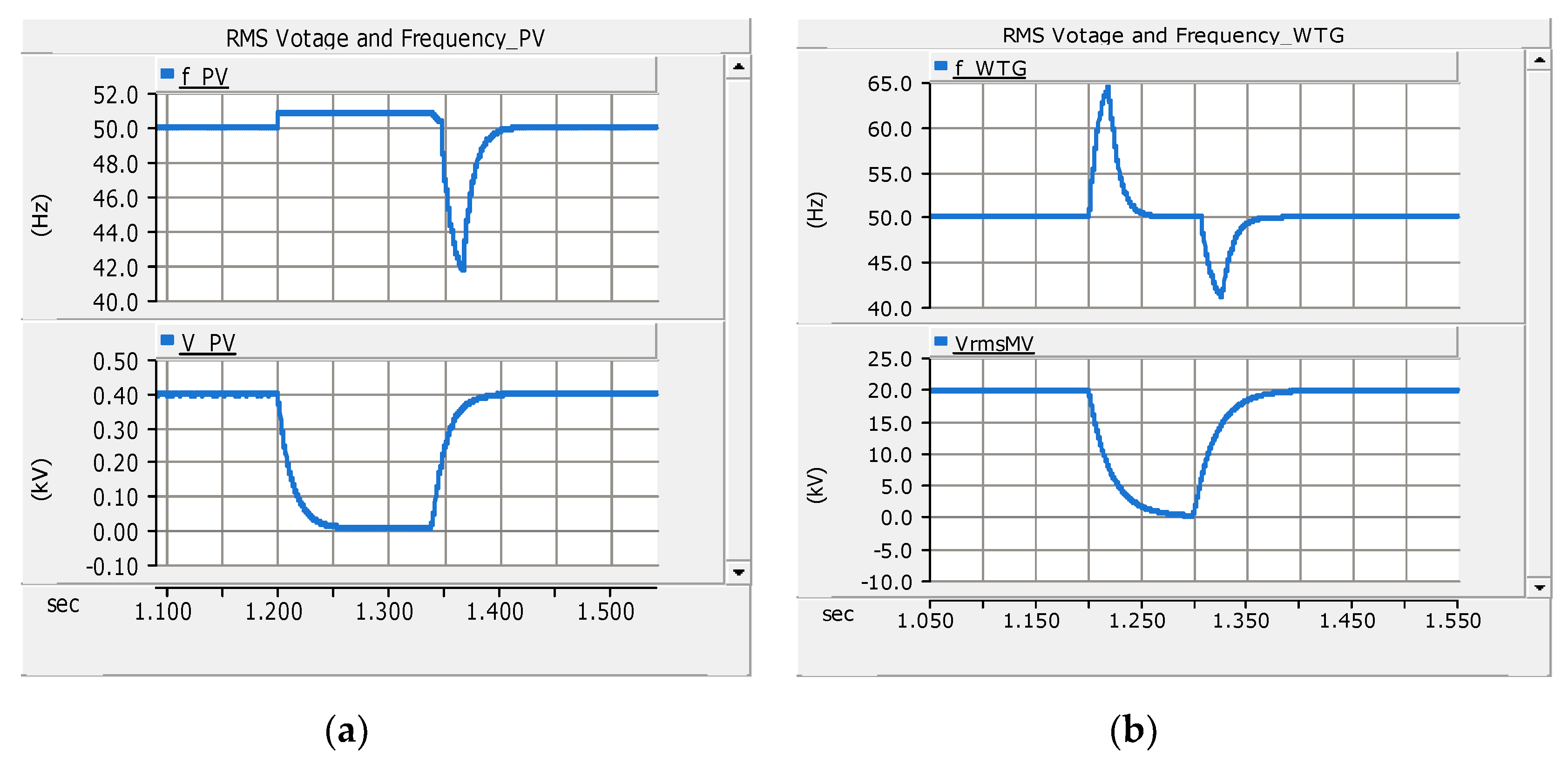
Figure 20 shows the RMS currents of DGs before, during and after the fault F2 in islanded mode with fault clearance using CB2 direct transfer trip.
Figure 21 shows the active and reactive power supply from DGs before, during and after the fault F2. Additionally, it is shown in
Figure 22 and
Figure 23 how smoothly two islands are formed within the islanded AC microgrid after the clearance of the fault F2 at 1.34 s. The results of adaptive IED7 tripping after transfer trip failure from IED6 during the fault F2 are not included to avoid repetition, in which case the adaptive IED7 may detect the fault with the lower settings (SG
IM) just like the adaptive IED2, as explained in
Section 4.1. In that case, the adaptive IED7 will wait until the time of direct transfer trip is elapsed; this is considered as a transfer trip failure from IED6. The adaptive IED7 will then decide to trip CB7 with the lower settings for the complete clearance of the fault F2 during transfer trip failure. It should also be noted that the WTG is comparatively stronger source than the PV system. Therefore, for faults F3, F4 or F5 in islanded AC microgrid (CB1 and CB2 open in
Figure 2), the WTG may still provide sufficient fault current, and the higher current settings (SG
GM) for IED7, IED8 and IED9 may still work for any of the faults F3–F5 downstream of the WTG. For these faults (F3–F5), the current comparison method to find the location of the faults (upstream or downstream faults) will also be valid for the islanded mode with the WTG in operation. However, after the removal of the fault F2 (CB6 and CB7 open), two further islands will be created: the islanded MV system and the islanded LV system (
Figure 2). The islanded MV system will be supplied by only the WTG, and the islanded LV system will be supplied by only the PV system. In this situation, only the adaptive lower settings (SG
IM) of IED8 and IED9 will work. For any islanded scenario, IED3, IED4 and IED5 will always require lower adaptive settings (SG
IM).
The LVRT Capability of DGs
The DGs are required to remain connected to the network during the voltage dips or faults, and depending on the requirements, the DGs may be requested to feed-in short-circuit fault currents up to the agreed value (or according to the limits of DGs) in order to support the detection of faults. This is called the low-voltage ride through (LVRT), under-voltage ride through (UVRT) or fault ride through (FRT) requirement. In the grid-connected mode, the LVRT capability of DGs is usually required to maintain the stability of the system, since the disconnection of many DGs even for a fraction of a second may result in large voltage or frequency fluctuations, causing the voltage or frequency instability of the entire system. The synchronous generators are more sensitive to voltage dips, and hence, their LVRT requirements are considerably less stringent in comparison with the nonsynchronous generators, including the converter-based generators, which can remain connected for the extended durations. In the islanded mode of operation, not only the system stability is important, but also, the quick detection and isolation of the fault is equally important. Additionally, the protection coordination or selectivity between the main and backup protection has to be ensured.
Figure 24 shows the comparison of different LVRT requirements of nonsynchronous generators, including the converter-based generators, according to the previous German BDEW-2008 standard [
32] and the latest European Standard EN 50549-1:2019 adopted as the Finnish National Standard SFS-EN 50549-1:2019 [
47]. The DGs are required to remain connected in parallel with the LV or MV networks if the voltage at the connection point is above the voltage-time curves of
Figure 24 (red and black curves). Although, the LVRT requirements are expectedly limited to the most stringent curves, however, the network operators may define their own LVRT characteristics. These standards do not define the LVRT requirements for the islanded mode of operation. Therefore, a new LVRT characteristic was proposed in this paper for the islanded mode operation of the nonsynchronous DGs, including the converter-based DGs shown as a green voltage-time curve in
Figure 24. According to this new proposed LVRT characteristic, the DGs will remain connected to the islanded MV/LV microgrid for at least 2 s after the voltage dip or the fault and feed-in short-circuit current of at least 1.2 p.u. of the rated current. With the proposed LVRT characteristic, not only the stability of the islanded microgrid will be maintained, but also, a good protection coordination between adaptive IEDs will be ensured. The WTG and BESS (battery energy storage systems) with full-scale converters are capable of providing this requirement. Normally, in the presence of high-speed communication, the standard grid-connected LVRT curves will be used; however, in case of communication failure, the definite-time coordination of IEDs with the proposed LVRT curve will be applied.
5. Discussion
An adaptive OC protection for the AC microgrid using the IEC 61850 communication standard and LVRT capability of DGs is presented in this paper. Previously, an adaptive OC protection was presented in [
48]; the scheme updated the inverse-time OC relay curve by changing the pick-up current with respect to DG infeed, but the focus was mainly on medium impedance faults at the end of the radial distribution network detected by a single-substation relay. The similar type of adaptive OC protection was proposed in [
49] for distribution networks with DGs using local data and two-setting groups for the inverse-time OC relay. However, the scheme does not use remote data by communication systems and is prone to nuisance and slow trips, resulting in DG loss. A directional adaptive inverse-time relay was presented more recently for HIL (Hardware-In-Loop) testing, and real-time simulations in [
50,
51]. In these papers, an FCL was used for limiting the wind turbine generator fault contribution, and its effects on relay settings were observed. This directional adaptive inverse-time relay using a multiagent system does not consider/mention the effects of communication delays on protection coordination. Moreover, it involves tedious calculations to generate various inverse time setting groups for changing the network configurations and those for all relays in the networks. Although, traditionally, inverse-time OC performs better than definite-time OC in terms of the minimum operation time close to the power source, but in the AC microgrid environment with many DG sources, this may not be completely true. The inverse-time OC relays are affected the most with the increased penetration level of DGs [
4], and it is the usual practice to limit the fault contribution from DGs to overcome the adverse effects, as it was also done in [
51]. An adaptive OC protection for distribution networks was proposed in [
52] that calculated and applied the new settings of OC relays directly whenever any significant change in the network occurred. The algorithm presented did not use precalculated settings and was initiated either by the monitoring block in the coordination layer or energy management system during topology changes using the communication link. The scheme was verified using the real-time digital simulator (RTDS) and IEC 61850 GOOSE messaging. However, the adaptive OC scheme was implemented using a centralized approach; the type of DG unit was not specifically described, and higher coordination delays were used. Moreover, the proposed adaptive OC scheme also gave slower tripping times compared with the traditional OC relay in some cases. In this paper, the communication-based definite-time OC relays with only two predefined setting groups are suggested. These two setting groups can be changed adaptively and quickly by each IED autonomously after receiving the status of DGs (on/off), CB status change (open/close), fault current magnitude and fault detection GOOSE signal from other IEDs. Moreover, the simple method of calculating the magnitude of the current at their locations, comparing it with the predefined threshold 1.2 p.u. of the max current and sharing this information with other IEDs will be useful for quick detection of the fault location after knowing the status of each DG. The nuisance tripping can also be avoided with fault current magnitude sharing between IEDs and with the careful use of trip block/release signals. The proposed current magnitude comparison method also avoids the additional measurement of voltage for the detection of the fault current direction. However, a voltage magnitude measurement can be used as a local backup protection for OC function. The proposed scheme in this paper can also be extended to low impedance single-phase ground faults and other asymmetrical faults. The method proposed in this paper will be evaluated with a real-time digital simulator of OPAL-RT for hardware-in-the-loop (HIL) simulations using actual Ethernet-based GOOSE communication between IEC 61850-based IEDs from different vendors for its practical implementation, and this will be presented in a separate research article in the future.


