Abstract
Shearer traction failure occurs frequently, which seriously restricts the safe and efficient mining of coal. However, the influence of the shearer’s posture on traction has not been fully considered in the existing research. To improve traction reliability: the dynamic model of the traction unit is established considering longitudinal swing; the walking characteristics of the shearer and the dynamics of the traction unit are analyzed; and the influences of traction velocity, drum load cutting arm angle, and depression angle are discussed. The results show that the longitudinal swing is reciprocating and the positive swing is more serious. With the increase of the traction velocity, the walking stability of the shearer decreases while the contact force increases, especially the support slipper. The longitudinal swing increases with the increase of lateral load, but the supporting force of the support slipper decreases with the increase of cutting load. The forces of the walking wheel and the support slipper show an increasing trend with the increase of cutting arm angle. When the depression angle is 5–10°, the load distribution of the contact components of the traction unit is more balanced. The results provide a reference for the structure optimization of the shearer and the layout of coalface.
1. Introduction
Coal plays an important role in the world energy security [1,2,3]. As key equipment of longwall mining coalface, the shearer is the key to achieve safe and efficient coal production [4,5,6]. The traction unit drives the shearer to move along the coalface and plays an important role in supporting and guiding the shearer. Shearer’s walking condition is bad, and the load is huge and complex [7]. There, the phenomenon of the shutdown caused by traction failure is frequent in actual production [8]. The reliability of the traction unit directly affects the working performance of the shearer and even the production efficiency of the coal mine. In addition, with the maturity of the ultra-height mining technology and the large-volume mine transportation and lifting technology, the application of high-power and high-speed shearers has become more popular, which puts forward higher requirements for the reliability of the traction unit [9]. Therefore, reducing the failure rate of the traction unit and improving its working life is the key to achieving safe and efficient mining of extra-thick coal seam.
The traction velocity directly affects the meshing quality of the walking wheels and the walking characteristics of the shearer [10], the force on the drum is the direct source of the shearer load [11], and the cutting arm angle affects the torque of the shearer [12]. These are the important factors affecting the mechanical property of the shearer traction unit. Furthermore, because of the complex terrain of the coalface, the position and posture of the shearer will change in the actual operation, and the shearer will swing due to the structural clearance between the traction contact parts. Affected by the complex terrain of mining coalface, the longitudinal swing of the shearer aggravates the impact of the key components of the traction unit, which makes the contact characteristics more complex. The contact characteristics and wear mechanism of the traction components are closer to the actual working conditions, in the research considering the longitudinal swing of the shearer. These can better provide data support for traction unit optimization design, in-depth reveal the influence mechanism of posture change on the traction unit, and provide a reference for reducing lateral wear of the guide slipper. Therefore, it is necessary to research the dynamic characteristics of the traction unit under the combined influence of multiple factors considering the longitudinal swing of the shearer and the meshing impact of the walking wheel.
Related scholars have conducted a lot of research on the shearer and its traction unit. Rui et al. [13] proposed a calculation method of cutting force and studied its effect on the traction drive system. Their result showed that the stress of the second-stage planetary gear was the largest, which was significantly affected by cutting load. Dan et al. [14] studied the influence of the system stiffness on the walking mechanism and reported that the meshing stiffness had the greatest influence and was negatively correlated with the velocity fluctuation amplitude and meshing force, which provided a reference for optimizing the walking characteristics of the shearer. Zhou et al. [15,16] proposed an evaluation method of the traction reliability, analyzed the dynamic response of the transmission system, and emphasized that the structural parameters of the sun gear had a greater impact on system reliability than other gears. Chen et al. [17,18] found the influence of pitch angle and roll angle on the mechanical properties of the slipper shaft by establishing a rigid–flexible coupling simulation model of shearer with clearance. Yang et al. [19] established a traction–swing coupling nonlinear dynamic model of the shearer. They found that the vibration of each component increased with the increase of speed and coalface hardness, after studying the dynamic response of key components of the shearer. Yuan [20] studied the dynamics of the shearer traction unit under different working conditions. The research showed that the shearer’s slippers were unevenly loaded and largely on rear slippers, and the impact load of the drum had a significant effect on the support slipper. Song et al. [21] reduced the height of the traction unit by 61 mm through structural optimization, and the vibration amplitude was significantly reduced. After studying the meshing property of the walking wheel, Wan et al. [22] emphasized that the unbalanced load on the tension side was more serious, and the impact load amplitude had a greater impact on it. Mao et al. [23,24] tested the dynamic property of the traction and reported that the load impact of the guide slipper was largest in the walking direction, and the load of the support slipper had the largest load in the vertical direction.
In the existing studies, a lot of research has been done on the reliability of the traction unit, contact characteristics of key traction components, and dynamic characteristics of the transmission system. However, this still cannot fully reveal the failure mechanism of shearer posture change on the traction key components. Besides, most of the existing researches have conducted independent studies on the guiding slipper, the supporting slipper and the walking wheel. But this cannot deeply explore the impact contact law of shearer traction components under complex terrain environment. Therefore, the dynamic model of shearer traction unit considering the longitudinal swing is established in this paper, which takes into account the coupling effect of shearer’s posture and cutting unit, and fully considers the influence of meshing impact between walking wheel and pin track on traction unit. In the results of this paper, the influence of traction velocity, drum load cutting arm angle, and depression angle on the dynamic property of the traction unit is obtained. This research provides a reference for the design and operation parameters selection of shearer with complex posture changes.
2. Materials and Methods
2.1. Traction System Simulation and Modeling
To study the dynamic of the shearer traction unit, a digital virtual prototype model of the shearer is established referencing the type of MG650/1620, as is shown in Figure 1. The model adopts an involute tooth–pin meshing walking mechanism, with the walking wheel of 11 teeth and the pin track pitch as 147 mm. In the longwall coalface, the force conditions of the left traction unit in the forward stroke (v-direction) and backward stroke are similar to the force conditions of the right traction unit in the backward stroke and forward stroke, respectively. Therefore, in order to focus on the difference caused by longitudinal swing, the shearer is simplified into the single cutting and traction, neglecting the rotation in the plane of xoy and xoz, considering the translation in three directions and rotation around the direction of travel. Thus, the multi-body dynamic simulation model of a unilateral shearer is established. The model adopts a rigid spring equivalent to replace the hydraulic cylinder [25], and assumes that the load distribution of the left and right traction parts is balanced, and the coal seam is approximately level.
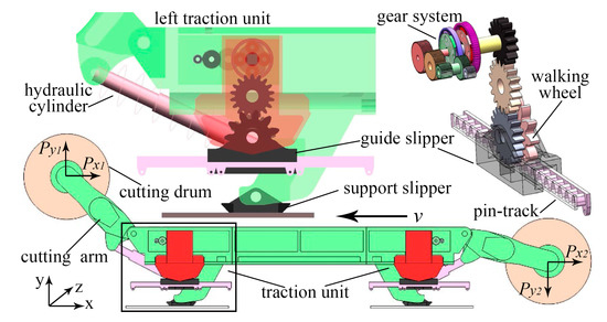
Figure 1.
Prototype model of the shearer and its traction unit.
2.2. Load and Contact Model
The external load of the shearer in the mining is mainly generated from cutting coal, so the load is equivalent to the three-way force at the drum center of gravity. The direction of the cutting force Py is related to the rotation of the drum. In this model, the direction of Py on the left drum is set along the positive y-axis, and its value is shown as:
where, Ph is the rated power of the cutting motor, η is the mechanical efficiency of the cutting unit; n is the drum velocity, and d is the diameter of the drum.
The direction of forward resistance force Px is opposite to the shearer traction direction, and its value is related to the wear degree of shearer pick [26], it is shown as:
where, K1 is the coefficient of pick wear.
The shearer lateral force Pz points from the coal wall to the goaf along the negative direction of the z-axis, which is related to the drum structure parameters and the pick distribution [27], and is shown as:
where, B is the cutting width of the picks on the drum end plate, K2 is the coefficient of cutting condition, and H is the cutting depth.
The simulation model is driven by the angular velocity of the walking wheel. According to the traction velocity of 0.167 m/s (10 m/min), under the typical working condition of the shearer, the angular velocity of the walking wheel is set. The contact model of the walking wheel, guide slipper, and support slipper is established by the impact function, and the contact force equation is shown as:
where, k is the contact stiffness coefficient, x1 is the initial displacement, x is the measured displacement; d is the penetration depth at maximum damping, Cmax is the maximum contact damping, and e is the nonlinear force index.
2.3. Simulation Processes
The simulation in this study was divided into five parts to study the dynamic properties of the shearer traction unit. In the first part, the walking characteristics of the shearer and the mechanical properties of the walking wheel, guide slipper and support slipper were studied under typical working conditions. The model was set with the traction velocity as 0.167 m/s (10 m/min), Px and Py as 45 kN, Pz as 25 kN, and the left cutting arm angle θ (the angle between the rocker arm and the walking plane) as 40°. In the second part, the influence of different traction velocity within 0.0833 m/s to 0.2 m/s (5–12 m/min) on the dynamic properties of the traction unit was studied. In the third part, the influence of the drum load on the traction unit was researched. And the model was set with Pz as 25 to 40 kN, Px as 25 to 65 kN, and Py as 45 to 60 kN. In the fourth part, the influence of the left cutting arm angle θ on the traction unit was studied, with the angle as 30–40°. In the fifth part, the influence of the depression angle was studied, with the angle as 0–20°.
3. Result Analysis and Discussion
3.1. Analysis of Shearer Walking Characteristics and Traction Unit Dynamics
The traction velocity and swing angle around x-axis of shearer under typical working conditions are extracted, as is shown in Figure 2. The simulation results show that the traction velocity fluctuates periodically and is basically consistent with the theoretical value of 0.167 m/s, which reflects the credibility of the simulation model to a certain extent. Besides, the rotation angle curve shows that the shearer has a reciprocating deflection movement around the x-axis in the doz plane, the period is 0.883 s. This indicates that there is discontinuous collision contact on the two sides of the guide slipper, under the action of lateral force, due to the clearance between the two sides of the guide slipper and the pin track. It may be an important reason for the frequent wear and failure of the guide slipper. And the coal gangue particles on the surface of the pin track will aggravate the damage. The maximum positive deflection angle (drum deflects to the goaf) is 0.1034°, and the maximum negative deflection angle is 0.0802°. The shearer’s positive deflection is relatively serious because the lateral force Pz points to the goaf along the negative direction of the z-axis. This shows that the longitudinal swing of the shearer will affect the contact clearance and wear amount of the slipper. Furthermore, the traction velocity increases slightly in the process of positive deflection of the shearer, which indicates that there is an interaction between the posture and the walking characteristics of the shearer.
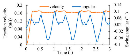
Figure 2.
The traction velocity and swing angle.
The walking wheel drives the shearer to move along the coalface by meshing with the pin track, and its characteristic curve of the contact force is shown in Figure 3 under typical working conditions. The results show that the x-direction component force of the walking wheel fluctuates periodically around 64 kN, which provides traction power for the shearer. The y-direction component force fluctuates periodically around 128 kN, which provides the y-direction supporting force for the shearer. In addition, the regularity of the periodic fluctuations of the y-direction force is more obvious, and the amplitude changes are greater. The peak value of the contact force is 138.9, 139.1, and 138.8 kN at 1.024, 1.920, and 2.805 s respectively, which is caused by the meshing impact between the walking wheel and the pin track. The average period of the peak force is 0.891 s, which is basically consistent with the theoretically calculated meshing period as 0.882 s of the walking wheel. Furthermore, the results show that the supporting load on the walking wheel is significantly greater than the traction load, without considering the coal seam angle and pitch angle. This indicates that the failure risk of the walking wheel increases due to the increase of cutting load in hard coal seam, which is consistent with the increase in the frequency of tooth breakage frequency of the walking wheel in actual mining. Therefore, it is necessary to optimize the overall structure of the traction unit and to optimize the mining process, so that the support slipper can share more supporting load to improve the overall life of traction unit. Besides, due to the cutting force of the front drum, the shearer tends lifting the front part, and the unilateral support slipper is out of contact, which aggravates the y-direction load of the walking wheel. This is the key factor that should be considered in the design of the walking wheel.
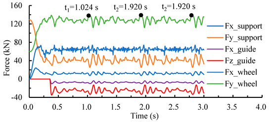
Figure 3.
Contact force curve of traction key components.
The support slipper is located near the coal wall side of the shearer, mainly providing y-direction support for the shearer, and its contact force curve under typical working conditions is shown in Figure 3. The y-direction force is mainly produced by the squeeze of the support slipper against the scraper conveyor. This force provides the y-direction supporting force for the shearer to overcome gravity. The simulation results show that the y-direction force is large and decreases rapidly at the start-up, and enters the stable stage at 0.25 s. This phenomenon is consistent with the simulation results in reference [17]. This is because the direction of cutting load is opposite to gravity, and the cutting load is gradually added using the step function in the simulation start-up stage until it reaches a stable value of 45 kN at 0.25 s, resulting in a decrease of the contact force during the loading stage. Besides, the x-component is the friction force between the support slipper and the scraper conveyor, which is related to the supporting load. In the stable stage, the average value of the x-direction force is 12.1 kN while the average value of the y-direction force is 40.7 kN, which basically meets the Coulomb friction theory.
The guide slipper is located on the goaf side of the shearer, which mainly provides the z-direction support and guides the shearer to move along the pin track. The contact force curve of support slipper under typical working conditions is shown in Figure 3. The result shows that the peak force of the z-direction force is about 33.5 kN, and the peak force appears at the same time as the maximum positive deflection angle of the shearer. This indicates that the main contact position of the guide slipper is the side near the coal wall, which is easy to wear and failure. This conclusion is consistent with the stress concentration position of the guide slipper in the existing research [28]. This is because of the extrusion of the coal wall, the shearer drum tends to deflect to the goaf, and the contact clearance between the guide slipper and the pin track decreases and the contact pressure increases. Therefore, in design optimization, the anti-wear design should be considered in this position. In addition, it can be considered to increase the depression angle properly, to relieve the lateral force of the drum through the gravity component force and reduce the side wear of the slipper.
3.2. Influence of Traction Velocity on Dynamic Properties of Traction Unit
In the simulation, 0.0167 m/s (1 m/min) is taken as the design interval, eight kinds of angular speed of the walking wheel are obtained according to different traction velocities v. And the walking characteristics and the dynamics of traction under different traction velocities are studied, as is shown in Figure 4. The simulation results show that the actual walking velocity of the shearer has a similar fluctuation law under different traction velocity, as is shown in Figure 4a. And with the increase of traction velocity, the fluctuation amplitude and frequency both increase, and the walking stability of the shearer decreases. Combining the analysis based on the numerical simulation results of LS-DYNA in reference [29], this is because the single-tooth meshing period of the walking wheel is shortened and the meshing impact is intensified, with the traction velocity increases. Therefore, in the development of high-speed shearer, the mechanical characteristics of the walking wheel can be used as the reference index of the walking stability of the shearer. The walking stability of the shearer can be improved by optimizing the meshing quality of the walking wheel.
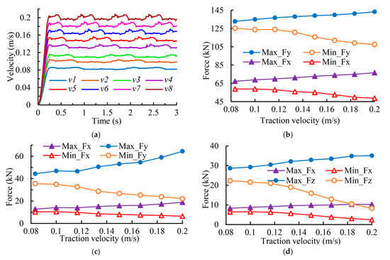
Figure 4.
Dynamic properties of traction unit at different traction velocities: (a) Actual walking velocity of the shearer; (b) Contact force of the walking wheel; (c) Contact force of the support slipper; and (d) Contact force of the guide slipper.
The contact force causes damage to the contact position, especially the greater the amplitude of the force fluctuation, the more significant the impact damage effect. Therefore, the maximum and minimum of contact forces of the walking wheel, support slipper, and guide slipper at different velocities in the stable phase are extracted, respectively, as is shown in Figure 4b–d. The results show that the maximum force of the walking wheel in the y-direction increases by 8% (10.6 kN) with the increase of velocity, the minimum decreases by 16.5% (17.7 kN), and the range increases to 35.7 kN. At the same time, the maximum force in the x-direction increases by 14% (9.4 kN), the minimum decreases by 20.9% (10.1 kN), and the range increases to 27.9 kN. Besides, the maximum force in the y-direction of the support slipper increases by 45.7% (20.2 kN), the minimum decreases by 37.8% (13.5 kN), and the range increases to 42.38 kN. Moreover, the maximum force in the z-direction of the guide slipper increases by 23.9% (6.4 kN), the minimum decreases by 22.6% (14 kN), and the range increases to 26.8 kN.
Thus, it is concluded that with the traction velocity increases, the maximum contact force of traction components increases, the minimum contact force decreases, and the range increases, especially for the support slipper. Furthermore, the increase of the maximum value and range of the contact force indicates that the contact impact between traction components and the scraper conveyor increases with the velocity increases. That aggravates the wear of the traction components. Because the scraper conveyor has no binding effect on the support slipper after the contact is broken off, the high-speed impact occurs between the support slipper and the scraper conveyor after the contact is restored. The conclusion shows that the impact force damage and material strength failure of traction components should be considered in the design of high-power and high-speed shearer, especially the support slipper.
3.3. Influence of Drum Load on the Dynamic Properties of the Traction Unit
The lateral force of the shearer is different due to the different drum structure parameters and the coalface layout. Therefore, the differences in the mechanical properties of the walking wheel, support slipper and guide slipper under Pz of 25, 30, 35, and 40 kN are studied, as is shown in Figure 5. The results show that with the increase of Pz, the fluctuation law of the y-direction force of the walking wheel is consistent, but the average force increases significantly, as is shown in Figure 5a,b, and the average force are 128.5, 139.2, 150.1, and 161.3 kN, respectively. This is because Pz is along the negative direction of the z-axis, and the increase of Pz aggravates the tendency of the shearer inclining to the side of the walking wheel, which leads to the increase of the walking wheel load in the y-direction. The lateral load is related to the coal cutting performance of the drum. Through the influence of Pz, the structural parameters of the drum affect the meshing characteristics of the walking wheel. Therefore, the optimization of drum structure parameters should be considered in the design of the traction unit. In addition, the average force in the x-direction of the walking wheel is basically the same as 61 kN, but the fluctuation is obviously intensified with Pz increases. In the stable operation stage, the variances of the x-direction force are 8.9, 10.3, 11.8, and 13.5 kN2, respectively. This is because the inclination of the shearer aggravates the uneven distribution of the longitudinal load of the walking wheel and deteriorates the meshing quality of the teeth-pin. Especially in the case of inclined mining, the gravity component increases the lateral load, which aggravates the wear of one side of the walking wheel.
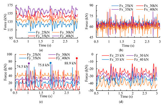
Figure 5.
Mechanical property of the traction unit under different lateral force: (a) The y-direction force of the walking wheel; (b) The x-direction force of the walking wheel; (c) The y-direction force of the support slipper; and (d) The z-direction force of the guide slipper.
As is shown in Figure 5c, the results show that the y-direction force of the support slipper is obviously affected by the lateral force. With the increase of Pz, the average value of the y-direction force of the support slipper decreases, but the maximum value increases, and the fluctuation of the force curve intensifies, with the variance as 32.6, 38.3, 45.7, and 64.1 kN2, respectively. It shows that the increase of Pz reduces the contact quality between the guide slipper and the scraper conveyor. The reason for the decrease of the average value is that as the Pz increases, the longitudinal inclination of the shearer is intensified, resulting in the load in y-direction biased to the side of the walking wheel, which is consistent with the results in Figure 5a. In addition, the maximum value increase is due to the contact impact of the support slipper resulting from the contact clearance increases. Especially, when Pz = 40 kN, the contact impact of the support slipper is obvious, with the minimum value of the y-direction force as zero and the maximum value as 88.9 kN. This indicates that the increase of lateral load will affect the continuous contact of the support slipper, increase the probability of the support slipper breaking off contact, and increase the supporting load of the walking wheel.
The z-direction force of the guide slipper is obviously affected by the Pz. With the Pz increases, the z-direction force increases, but the fluctuation law is basically the same, as is shown in Figure 5d. Combining with the analysis of Figure 3, this is because the extrusion between the guide slipper side and the pin rail is intensified with the increase of lateral force. This result indicates that the lateral force will increase the side wear of the guide slipper near the coal wall. Therefore, the depression angle of mining can be adjusted to reduce its axial load, thereby preventing excessive wear of the guide shoes. Besides, to improve the service life of the guide slipper, the lateral force can be reduced by optimizing the drum structure.
Due to the different wear degree of pick, the forward load of the shearer is different. Therefore, in order to study the influence of the forward load on the traction unit, Px is set as 25, 35, 45, 55, and 65 kN, respectively. The results show that Px has a significant effect on the x-direction force of the walking wheel. With the increases of Px, the x-direction force increases as a whole, and the fluctuation law is basically the same, as is shown in Figure 6. This is because the increase of Px only increases the walking resistance in the traction direction, and has little effect on the overall posture of the shearer. Combined with Equation (2), the cutting resistance of the shearer will increase and the x-direction force of the walking wheel will increase when the pick is excessively worn. Besides, the results show that the influence of Px on the mechanical properties of other components is weak. This is because the rotation around the z-axis is not considered in this model, which requires further in-depth study combining with the load distribution characteristics of double traction units.
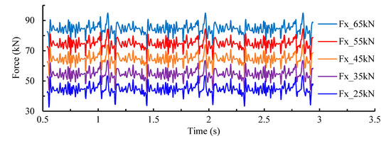
Figure 6.
The x-direction force of the walking wheel under different forward resistance force.
Affected by the drum movement parameters, the cutting force of the shearer is different. Therefore, to study the influence of the cutting force on the traction unit, the mechanical properties of the walking wheel and support slipper are obtained, after setting the Py as 25, 35, 45, 50, and 65 kN, respectively. The results show that with the increases of Py, the y-direction force of the walking wheel increases slightly, and the x-direction force decreases overall with the almost same maximum value, as is shown in Figure 7a,b. Besides, with the increase of Py, the forces of the support slipper in the y-direction and x-direction decrease significantly, as is shown in Figure 7c, which is coincided to the analysis of reference [18]. This is because Py will counteract gravity, and with the increase of Py, the meshing clearance increases between the walking wheel and the pin track, and the support load of the support slipper decreases. Especially when Py = 65 kN, the x-direction force of the walking wheel fluctuates significantly with obvious meshing impact, and the force of the support slipper increases sharply at 0.99 s. This result provides a reference for the parameter matching between the shearer drum and the traction unit.
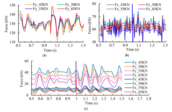
Figure 7.
Mechanical property of the traction unit under different cutting force: (a) The y-direction force of the walking wheel; (b) The x-direction force of the walking wheel; and (c) The force of the support slipper.
3.4. Influence of Cutting Arm Angle on the Dynamic Properties of the Traction Unit
In order to prevent cutting rock, the shearer will adjust the angle of the cutting arm according to the thickness of the coal seam. Therefore, to study the influence of cutting arm angle on the traction unit, the θ is set as 30°, 35°, 40°, 45°, and 50°, respectively. The simulation results show that the force of the walking wheel and the support slipper is affected by the θ, as is shown in Figure 8. The sharp increase of force has a great influence on the service life of the walking wheel. Thus, the average peak contact force of the walking wheel is obtained, after extracting the peaks which are larger than the average force and then taking the average value. The results show that with the increase of θ, the average peak force of the walking wheel in the y-direction is 129, 132, 137, 135, and 139 kN, and the average peak force in the x-direction is 63, 66, 70, 68, and 72 kN, respectively. Among them, the contact force decreases slightly when θ is 45°.
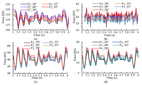
Figure 8.
Mechanical property of the traction unit under different cutting arm angle: (a) The y-direction force of the walking wheel; (b) The x-direction force of the walking wheel; (c) The y-direction force of the support slipper; and (d) The x-direction force of the support slipper.
As is shown in Figure 8a,b, in the stable operation stage of the simulation, with the increase of θ, the contact force of the walking wheel shows an overall increasing trend. This is because the center of gravity position of the shearer changes and the torque increases, after the cutting arm rotates. Therefore, the telescopic stability of the height adjusting cylinder of the cutting arm will affect the dynamic characteristics of the walking wheel. Furthermore, the high frequency pulsation of the hydraulic cylinder will aggravate the impact damage of the walking wheel. In addition, with the increase of θ, the contact force of the support slipper tends to increase, but the amplitude is smaller than that of the walking wheel, as is shown in Figure 8c,d. This shows that the impact of cutting arm angle on the contact force of the walking wheel is greater than that of support slipper. The conclusion provides a reference for cutting arm structure optimization and swing angle setting.
3.5. Influence of Depression Angle on the Dynamic Properties of the Traction Unit
The topography and geomorphology of underground coal mines are complicated. Therefore, the mining face adopts different layout techniques according to the characteristics of the coal seam. Among them, the wear of the traction unit is seriously in the process of underhand mining (coalface is lower than goaf), and the depression angle is an important factor affecting the longitudinal swing of the shearer. Therefore, the influence of the depression angle on the mechanical properties of the traction component is studied, with the depression angle as 0°, 5°, 10°, 15°, and 20°, respectively.
The results show that the overall fluctuation law of the supporting force curve of the walking wheel is less affected by the depression angle, but the supporting force decreases with the increase of the depression angle, as is shown in Figure 9a. This is because the increase of depression angle aggravates the incline of the shearer to the coal wall, and further increases the proportion of bearing gravity of support slipper. Therefore, this result indicates that the supporting force of the walking wheel can be reduced by appropriately increasing the depression angle of underhand mining. Besides, with the increase of depression angle, the axial force of the walking wheel is generated and tends to increase, and the trend weakens when the depression angle reaches 15°, as is shown in Figure 9b. The axial force is related to the longitudinal load distribution of the walking wheel. Therefore, this result shows that the increase of depression angle could reduce the longitudinal uniform load characteristics of the walking wheel tooth surface. Therefore, the axial force of the walking wheel should be taken as an important detection index in large angle underhand mining technology, to prevent excessive wear of the unilateral tooth surface from causing safety accidents. Moreover, with the increase of depression angle, the traction force of the walking wheel shows an increasing trend, as is shown in Figure 9c. When the depression angle reaches 10°, the meshing impact phenomenon of the walking wheel is obviously intensified, which is also related to the longitudinal unbalanced load. When the depression angle increases, there may be an angle difference between the meshing line of the walking wheel and the longitudinal direction of the pin teeth. The bearing capacity of the walking wheel decreases due to the decrease of the actual meshing area. Therefore, it is necessary to optimize the depression angle to reduce the load of the walking wheel, while ensuring that the longitudinal uniform load characteristic is in a reasonable range.
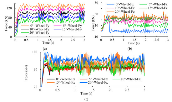
Figure 9.
Mechanical property of the walking wheel under different depression angle: (a) The supporting force in y-direction; (b) The axial force in z-direction; and (c) The traction force in x-direction.
As is shown in Figure 10a,b, with the increase of the depression angle, the supporting force in the y-direction of the support slipper increases, which is related to the lateral inclination of the shearer and further supports the analysis of Figure 9a. The x-direction force is not shown. Because of the x-direction force is basically linearly related to the supporting force, which satisfies Coulomb’s law. Besides, the longitudinal force of the support slipper is produced during the underhand mining process, and it tends to increase with the increase of the depression angle. This force includes the component force of the shearer gravity in the z-direction, and the longitudinal friction between the support slipper and the scraper conveyor.
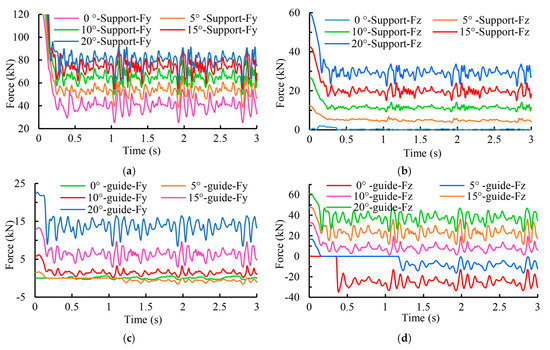
Figure 10.
Mechanical property of the slipper under different depression angle: (a) The supporting force of the support slipper; (b) The longitudinal force of the support slipper; (c) The supporting force of the guide slipper; and (d) The longitudinal force of the guide slipper.
As is shown in Figure 10c, when the depression angle is in the range of 0–5°, the supporting force of the guide slipper is small and the direction is uncertain. And with the increase of depression angle, the supporting force of guide slipper in y-direction becomes the positive value and trends to increases. A positive y-direction force indicates that there is an extrusion between the scraper conveyor and the upper side of the guide slipper. And when the angle reaches 15°, the depression angle of underhand mining has a significant effect on the y-direction force, and the wear on the upper side of the guide slipper is intensified. Furthermore, with the increase of depression angle, the z-direction force of the guide slipper first decreases and then increases; and the force begins to be positive when the angle is 10°, as is shown in Figure 10d. Combined with the analysis of Figure 3, the results show that when the depression angle is greater than 10°, the contact surface of the guide slipper changes from the side near the coal wall to the goaf side. This is because, with the increase of the depression angle, the tendency of the shearer sliding towards the coal wall side under the action of gravity component force increases, and the extrusion between the guide slipper and the pin track is intensified. This result provides a reference for the strengthened design of the guide slipper on the underhand coalface with the large depression angle.
Combining the analysis of Figure 9 and Figure 10, it is concluded that the depression angle has an important influence on the load distribution of the contact components of the traction unit, and the load distribution of each component within the range of 5–10° is more balanced. This provides a reference for the layout of the underhand coalface.
4. Conclusions
To improve the reliability of the shearer traction unit and provide the reference for its structural optimization, a multi-body dynamics model of the shearer traction unit considering longitudinal swing was established. The influences of traction velocity, drum load, and cutting arm angle on the walking characteristics of the shearer and the dynamic properties of the traction unit were studied.
The following conclusions were reached:
- (1)
- The shearer has a reciprocating swing around the x-axis in the yoz plane, and the positive deflection is more serious. In the process of positive deflection, the walking velocity increases slightly. When the forward deflection angle is the largest, the lateral force of the guide slipper is the largest. Therefore, by controlling the posture of the shearer, its dynamic properties and walking characteristics can be improved. The force of the walking wheel in the y-direction is obviously greater than that in the x-direction, and it is more affected by meshing impact.
- (2)
- With the increase of the traction velocity, the fluctuation amplitude and frequency of the actual walking velocity of the shearer increase, the walking stability of the shearer decreases, the contact impact of traction parts intensifies, and the contact force increases, especially the support slipper. Therefore, the wear failure of contact parts should be considered in the design of the high-speed shearer.
- (3)
- With the increase of Pz, the average supporting force and the fluctuation of the traction force of the walking wheel increase, the average supporting force of the support slipper decreases, but the peak force increases, the lateral force and the side wear of the guide slipper increase. With the increase of Px, the traction forces of the walking wheel increases. With the increase of Py, the traction force of the walking wheel decreases slightly while the supporting force increases, and the supporting force of the support slipper decreases.
- (4)
- With the increase of θ, the contact force of the walking wheel and the supporting force of the support slipper both show an increasing trend.
- (5)
- With the increase of depression angle: the support force of the walking wheel decreases, while the axial force and traction force increase; the support force and longitudinal force of support slipper increase; and the wear of the upper side and goaf side of guide slipper is intensified. When the depression angle is 5°-10 °, the load distribution of the contact components of the traction unit is more balanced. The conclusion provides a reference for the layout of underhand stopes and the design of traction components.
The multi-body dynamics model, established in this paper, can simulate the walking characteristics of the shearer during the traction process and the mechanical properties of the key components of the traction unit, which provides a reference for the design of the traction unit and the layout of coalface. However, in order to focus on the influence of lateral swing, this model only considers the left traction unit, and does not consider the load distribution between the double traction units. Therefore, it is necessary to further in-depth study of the lateral swing and traction properties of the shearer under the coupling effect of double traction units. In addition, the cutting unit and the traction unit can be combined to analyze, and consider the influence of more cutting characteristics on the traction unit, in the future research.
Author Contributions
Conceptualization, D.M. and L.W.; methodology, D.M., X.Z., and L.W.; software, D.M.; resources, Q.Z.; data curation, D.M. and L.W.; writing—original draft preparation, D.M.; writing—review and editing, D.M. and L.W.; visualization, D.M. and H.G.; supervision, X.Z.; project administration, X.Z. and L.W.; funding acquisition, L.W. and Q.Z. All authors have read and agreed to the published version of the manuscript.
Funding
This research was funded by Key Research and Development of Shandong Province (Exploration and Mining of Deep Resources, Grant No. 2019SDZY01), the Innovative Team Development Project of Ministry of Education (Grant No. IRT_16R45), Key Research and Development of Shandong Province (Grant No. 2018GGX103002), Postgraduate Science and Technology Innovation Project of Shandong University of Science and Technology (Grant No. SDKDYC190328).
Conflicts of Interest
The authors declare no conflict of interest. The funders had no role in the design of the study; in the collection, analyses, or interpretation of data; in the writing of the manuscript, or in the decision to publish the results.
References
- Dong, Y.; Di, J.; Wang, X.; Xue, L.; Yang, Z.; Guo, X.; Li, M. Dynamic Experimental Study on Treatment of Acid Mine Drainage by Bacteria Supported in Natural Minerals. Energies 2020, 13, 439. [Google Scholar] [CrossRef]
- Wang, K.; Huang, Y.; Gao, H.; Zhai, W.; Qiao, Y.; Li, J.; Ouyang, S.; Li, W. Recovery Technology of Bottom Coal in the Gob-Side Entry of Thick Coal Seam Based on Floor Heave Induced by Narrow Coal Pillar. Energies 2020, 13, 3368. [Google Scholar] [CrossRef]
- Szurgacz, D.; Brodny, J. Adapting the Powered Roof Support to Diverse Mining and Geological Conditions. Energies 2020, 13, 405. [Google Scholar] [CrossRef]
- Peng, S.S.; Du, F.; Cheng, J.; Li, Y. Automation in U.S. longwall coal mining: A state-of-the-art review. Int. J. Min. Sci. Technol. 2019, 29, 151–159. [Google Scholar] [CrossRef]
- Brodny, J.; Tutak, M. Analysis of Availability of Longwall-Shearer Based on Its Working Cycle. In Proceedings of the IOP Conference Series: Earth and Environmental Science; IOP Publishing Ltd.: Bristol, UK, 2017; Volume 95. [Google Scholar] [CrossRef]
- Gospodarczyk, P. Modeling and Simulation of Coal Loading by Cutting Drum in Flat Seams. Arch. Min. Sci. 2016, 61, 365–379. [Google Scholar] [CrossRef]
- Li, J.; Liu, Y.; Xie, J.; Wang, X.; Ge, X. Cutting Path Planning Technology of Shearer Based on Virtual Reality. Appl. Sci. 2020, 10, 771. [Google Scholar] [CrossRef]
- Zhou, D.; Zhang, X.; Zhang, Y. Dynamic reliability analysis for planetary gear system in shearer mechanisms. Mech. Mach. Theory 2016, 105, 244–259. [Google Scholar] [CrossRef]
- Hoseinie, S.H.; Khalokakaie, R.; Ataei, M. Reliability-based maintenance scheduling of haulage system of drum shearer. Int. J. Min. Miner. Eng. 2011, 1287–1292. [Google Scholar] [CrossRef]
- Mao, J.; Yang, X.; Chen, H.; Song, Q. Analysis of shearer vertical direction vibration characteristics under different haulage speed. J. Mech. Strength 2018, 40, 1287–1292. [Google Scholar] [CrossRef]
- Ordin, A.A.; Nikol’sky, A.M. Optimizing Cutting Width and Capacity of Shearer Loaders in Longwall Mining of Gently Dipping Coal Seams. J. Min. Sci. 2018, 54, 69–76. [Google Scholar] [CrossRef]
- Reid, A.W.; McAree, P.R.; Meehan, P.A.; Gurgenci, H. Longwall Shearer Cutting Force Estimation. J. Dyn. Syst. Meas. Control. Trans. ASME 2014, 136, 031008. [Google Scholar] [CrossRef]
- Zhang, R.; Zhang, Y. Dynamic model and analysis of the traction unit gear system in long wall coal shearer. Proc. Inst. Mech. Eng. Pt. K J. Multi Body Dyn. 2020, 234, 546–567. [Google Scholar] [CrossRef]
- Zhang, D.; Liu, Y.; Qi, L.; Wan, F. Rigidity of traveling part in MG2040 mode coal shearer affected to dynamics features. Coal Sci. Technol. 2017, 45, 150–181. [Google Scholar] [CrossRef]
- Zhou, D.; Zhang, X.; Zhang, Y. Reliability analysis of the traction unit of a shearer mechanism with response surface method. J. Mech. Sci. Technol. 2017, 31, 4679–4689. [Google Scholar] [CrossRef]
- Zhou, D.; Zhang, X.; Yang, Z.; Zhang, Y. Vibration reliability analysis on tractive transmission system of shearer. J. China Coal Soc. 2015, 40, 2546–2551. [Google Scholar] [CrossRef]
- Chen, H.; Zhang, K.; Wang, X.; Song, Q.; Mao, J. Analysis of the dynamics characteristics of shearer sliding boots based on roller experimental load. J. China Coal Soc. 2017, 42, 3313–3322. [Google Scholar]
- Chen, H.; Zhang, K.; Piao, M.; Wang, X.; Mao, J.; Song, Q. Virtual Simulation Analysis of Rigid-Flexible Coupling Dynamics of Shearer with Clearance. Shock Vib. 2018, 2018, 1–18. [Google Scholar] [CrossRef]
- Yang, X.; Chen, H.; Mao, J.; Wei, Y. Dynamical Behavior of Coal Shearer Traction-swing Coupling under Corrected Loads. Sci. Rep. 2020, 10, 8630. [Google Scholar] [CrossRef]
- Yuan, B. Analysis of Shearer’s Haulage Unit Dynamics and Walking Wheel Fatigue Life under Typical Working Conditions. Master’s Thesis, Taiyuan University of Technology, Taiyuan, China, 2018. [Google Scholar]
- Song, X.; Ge, H.; Qian, L.; Zhang, X. Optimization Design and Vibration Characteristics Analysis of Drum Shearer’s Haulage Unit. In Proceedings of the 2nd World Conference on Mechanical Engineering and Intelligent Manufacturing, Shanghai, China, 22–24 November 2019. [Google Scholar]
- Wan, L.; Ma, D.; Zhang, X. Research on Meshing Characteristics of Shearer Walking Wheel Based on Rigid-Flexible Coupling. Math. Probl. Eng. 2020, 2020, 8301086. [Google Scholar] [CrossRef]
- Mao, J.; Yang, X.; Chen, H.; Song, Q. Experimental research on dynamic characteristics of shearer haulage unit, Machine Design and Research. Mach. Des. Res. 2018, 34, 143–147. [Google Scholar] [CrossRef]
- Wang, C.; Wang, C.; Mao, J.; Hao, Z.; Wang, S. Analysis and experimental research on load characteristics of smooth shoe pin of shearer. Mach. Des. Res. 2017, 33, 177–181. [Google Scholar] [CrossRef]
- Yang, Z.; Sun, Z.; Jiang, S.; Mao, Q.; Liu, P.; Xu, C. Structural Analysis on Impact-Mechanical Properties of Ultra-High Hydraulic Support. Int. J. Simul. Model. 2020, 19, 17–28. [Google Scholar] [CrossRef]
- Mao, J.; Wang, X.; Chen, H.; Zhang, Y. The influence of the driving speed of the traveling mechanism of the coal mining machine on the random load of the roller. J. Mech. Strength 2018, 40, 274–279. [Google Scholar] [CrossRef]
- Gu, E. Analysis and Research on the Wear Resistance and Strength of the Guide Shoe of Shearer. Master’s Thesis, China Coal Research Institute, Beijing, China, 2017. [Google Scholar]
- Zhao, L.; Sun, D.; Sun, L. Research on simulation of rigid-flexible coupled system of shearer haulage unit, Journal of Mechanical Transmission. J. Mech. Transm. 2012, 36, 17–20. [Google Scholar]
- Zhou, J.; Liu, Y.; Liu, S.; Du, C. Characteristic analysis of dynamic meshing for shearer walking mechanism. Chin. J. Eng. Des. 2013, 20, 230–235. [Google Scholar] [CrossRef]


© 2020 by the authors. Licensee MDPI, Basel, Switzerland. This article is an open access article distributed under the terms and conditions of the Creative Commons Attribution (CC BY) license (http://creativecommons.org/licenses/by/4.0/).