Article

Study on Bearing Capacity of Tank Foundation with Alternatively Arranged Vortex-Compression Nodular Piles

Department of Civil Engineering, China University of Petroleum (East China), Qingdao 266580, China
*
Author to whom correspondence should be addressed.
Energies 2020, 13(20), 5273; https://doi.org/10.3390/en13205273
Submission received: 8 September 2020 / Revised: 6 October 2020 / Accepted: 8 October 2020 / Published: 11 October 2020
(This article belongs to the Section G: Energy and Buildings)

Abstract

:
Types of tapered piles are widely applied in tank foundation consolidation, but their inherent deficiencies in design and construction limit their further promotion. Vortex compression pile is a novel nodular pile. Compared with the traditional equal-section pile, vortex compression nodular pile is featured by stronger bearing capacity and slighter settlement. In this paper, the model test results showed that vortex compression nodular pile can greatly improve the bearing capacity and reduce the settlement. Through the finite element software ABAQUS analysis the bearing characteristics of equal-section pile foundation and vortex-compression nodular pile foundation were compared. The three-dimensional solid model was established by ABAQUS finite element software. The impact of cushion modulus, cushion thickness, vertical load, pile modulus, soil modulus around the pile on the bearing capacity of the vortex-compression nodular pile foundation were studied.

1. Introduction

In China, most storage tanks in oil and gas reserve projects, with a volume larger than 105 m3, are built on soft foundation area [1]. These tanks are featured by large volume and heavy load, putting strict requirements on the bearing capacity of tank foundation and the control of uneven settlement [2]. At present, because of improper site selection, poor foundation consolidation, and improper foundation structure form, uneven settlement of tank foundation has become outstanding, which results in tank body tilt, floating roof displacement and sticking, tank body distortion, and other related problems [3,4]. Therefore, how to strengthen the foundation, improve the bearing capacity, and mitigate the uneven settlement while saving resources have been the focuses of civil engineering workers [5].
Through the analysis of compaction test in specific projects, Lin P. concluded that gravel pile reinforcement can improve the bearing capacity of tank foundation by compacting soil, which is simple in construction, mature in technology, and can save a lot of cement and steel [6]. Jia J carried out static load test, dynamic penetration test, and standard penetration test on gravel pile composite foundation. They concluded that the modulus of cushion under flexible foundation should fall in the range of 80–200 MPa and reported critical pile length for certain load capacity and strain. They also suggested that appropriate replacement rate can give full play to the load capacity of soil [7]. Combined with the specific engineering geology and trial pile result data of the Cement Fly-ash Gravel(CFG) pile composite foundation of Dongying storage tank, Dong H. obtained the settlement of the foundation under circular uniform load and the load transfer law of the pile body [8]. Song X. simulated the CFG pile by ADINA finite element software. He found that the force mode of side pile and middle pile are not exactly the same, so their load transfer law is also different. Besides, the pile-soil stress ratio is directly proportional to the cushion modulus and increasing the cushion thickness or reducing the cushion modulus can mitigate the stress concentration [9]. Li P. simulated the vibroflotation gravel pile by PLAXIS finite element software, the differential settlement under different pile length, replacement rate, pile diameter and pile spacing are studied. He concluded that the differential settlement is negatively correlated with the replacement rate, and pile diameter [10]. Through numerical simulation, Liu H. concluded that the influence of tank group effect on foundation settlement is negatively correlated with the load on the tank foundation [11].
In 2014, Li C. et al. proposed the vortex compression nodular pile, developed the equipment and tools for construction, secured national invention patent, and put forward a new method for tank foundation consolidation, that is, the vortex compression nodular pile foundation with alternatively arranged nodular parts [12,13,14]. Through indoor model tests, the load transfer mechanism of vortex-compression nodular pile and the distribution law of side friction along the pile under different loads are studied. This paper focuses on the vertical bearing capacity and the settlement behavior of vortex-compression nodular pile as well as the development law of the plastic failure zone of the soil around the nodular parts [15,16,17,18]. Through the numerical simulation of ABAQUS software, the influence factors of pile foundation with alternatively arranged nodular parts are analyzed. The foundation settlement and pile-soil stress ratio under different pile modulus, soil modulus around pile, cushion modulus, cushion thickness and load are studied [19,20,21].

2. Experimental Work

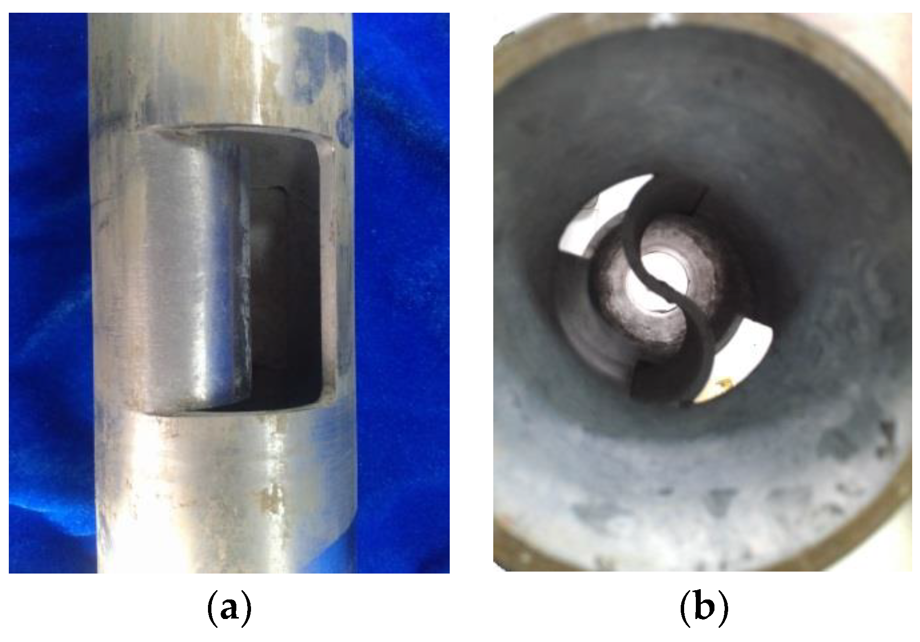
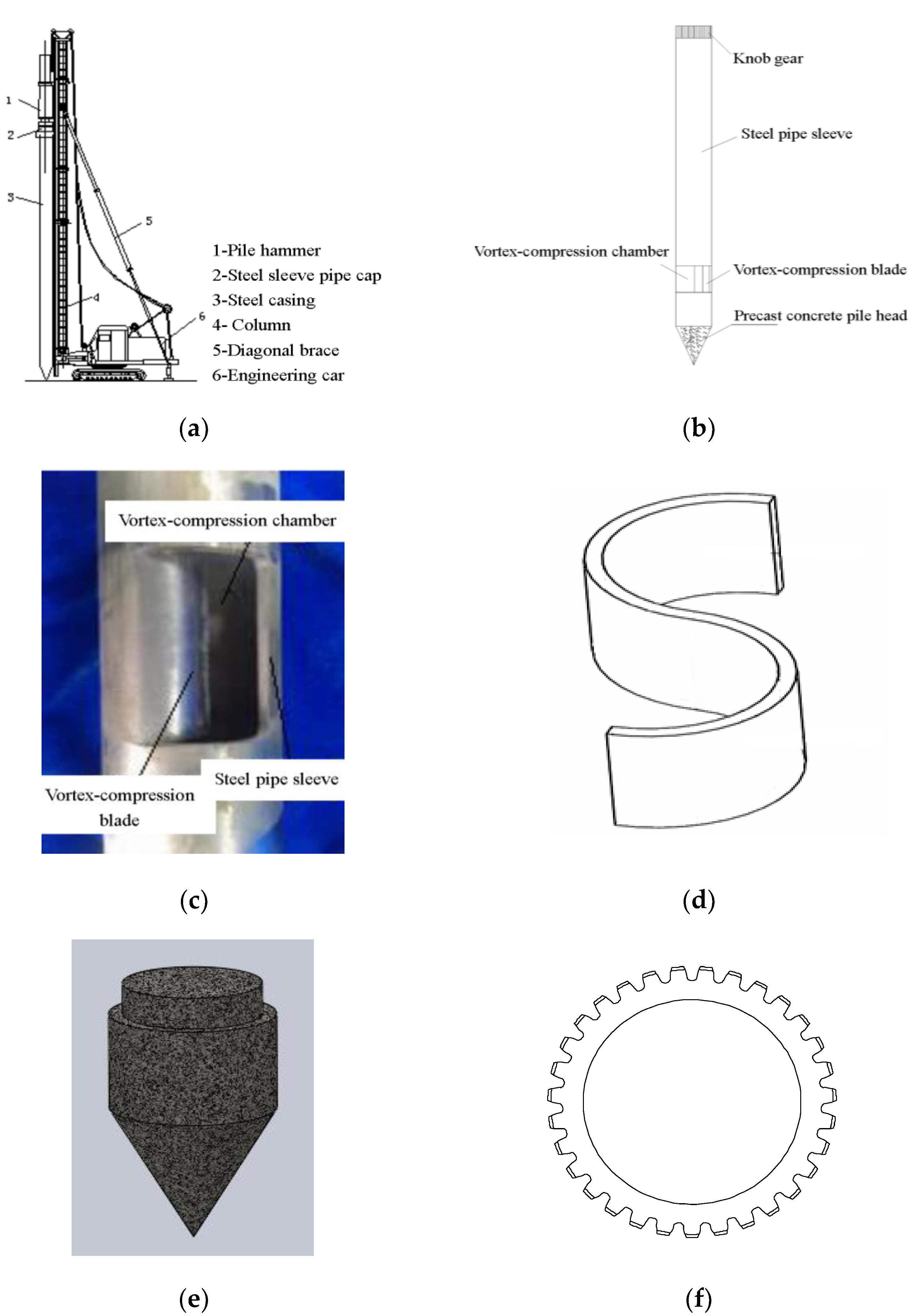
2.1. Technical Information of Pile Forming

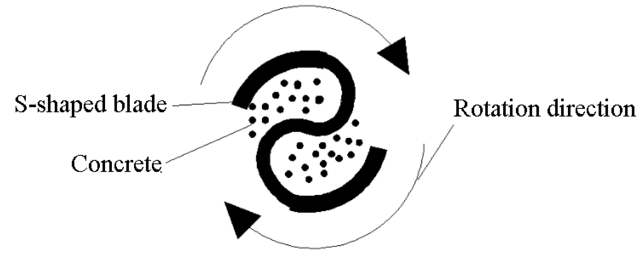
2.1.1. Pile Forming Mechanism

Figure 1 and Figure 2 present the pile forming mold and structure diagram of the nodular pile.
With the help of the rotating S-shaped blade as shown in Figure 2, the pile-forming tool of the nodular pile creates a vortex and squeezes the concrete in the pipe into the surrounding soil so as to form the nodular part.

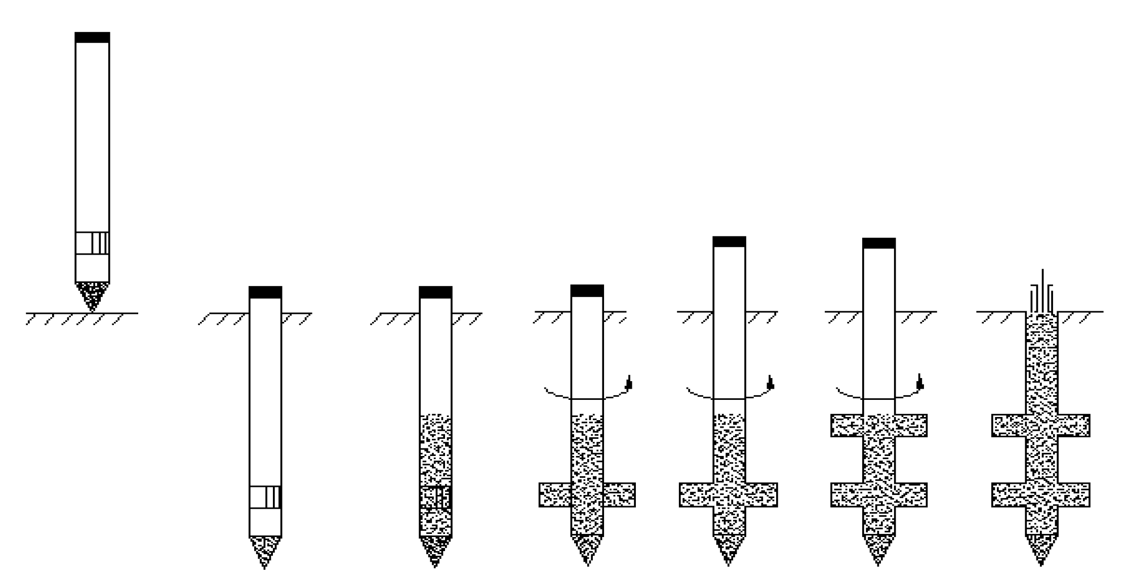
2.1.2. Pile-Forming Process

The pile-forming equipment of vortex-compression nodular pile mainly includes two parts: vortex-compression steel pipe and pile frame; the vortex-compression steel pipe is composed of knob gear, steel pipe sleeve, vortex-compression blade, vortex-compression chamber, and precast concrete pile head; the pile frame is composed of pile hammer, steel sleeve pipe cap, steel casing, column, diagonal brace, and engineering car, etc., as shown in Figure 3.
The construction process is shown in Figure 4.
Step 1:
Determine the position using the concrete precast pile head and make the pile steel pipe in place.
Step 2:
Drive the steel casing to the designated depth by using the pile frame equipment, and remove the hammering equipment.
Step 3:
Inject pre-calculated volume of concrete into the steel pipe through the pipeline.
Step 4:
Install the rotary torsion equipment and rotate the steel pipe to form the first nodular part.
Step 5:
Slowly rotate the steel pipe in the same direction and lift it to the next depth where the nodular is designed.
Step 6:
Continue to rotate the steel pipe to form the next nodular part by using the rotating and twisting equipment.
Step 7:
Inject the concrete until it returns to the pile top elevation, rotate and retrieve the steel pipe, and finally place the reinforcement cage.
The vortex-compression nodular pile is thus formed.

2.2. Experimental Work Set Up

The iron model box with a wall thickness of 10 mm, inner diameter of 1000 mm, and height of 1200 mm (Figure 5a) was placed on the rigid floor in the laboratory. Four holes were evenly drilled in the bottom plate of the box. Porous stones placed under the bottom plate allowed the drainage of the supersaturated water in the foundation soil (Figure 5b). Longitudinal and transverse stiffening ribs were fitted on the outer wall to enhance the rigidity of the model box. The box was big enough to hold soil and piles.
A load cell (of 100 kN capacity) was fitted on the top of the test pile. Above the load cell lied a plunger connected to the steel frame. The plunger applied a downward reactive force to the pile. This force was regulated by a hydraulic jack which was attached to the top of the steel frame. A load sensor with dial indicators was fitted at the top of the pile. Two dial indicators were fixed on a special dial indicator bracket through a magnetic stand (Figure 6). The dial indicator bracket was placed on the flat and rigid ground.

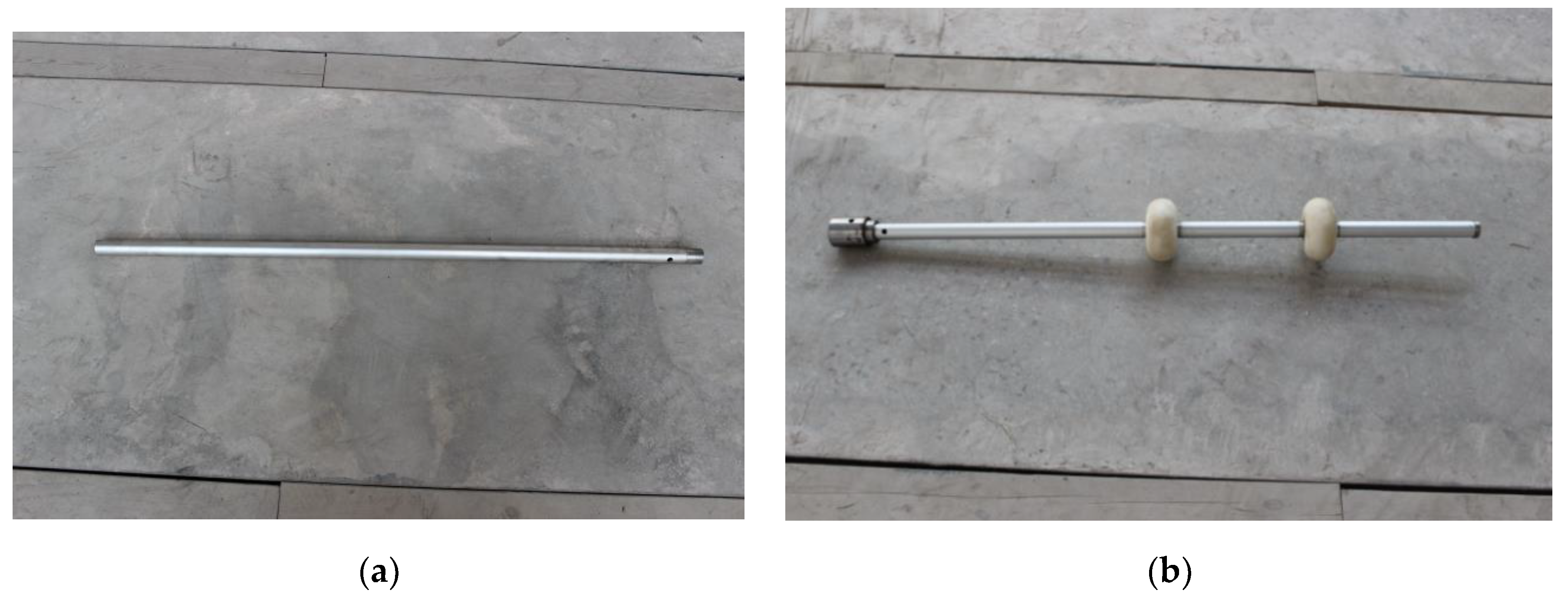
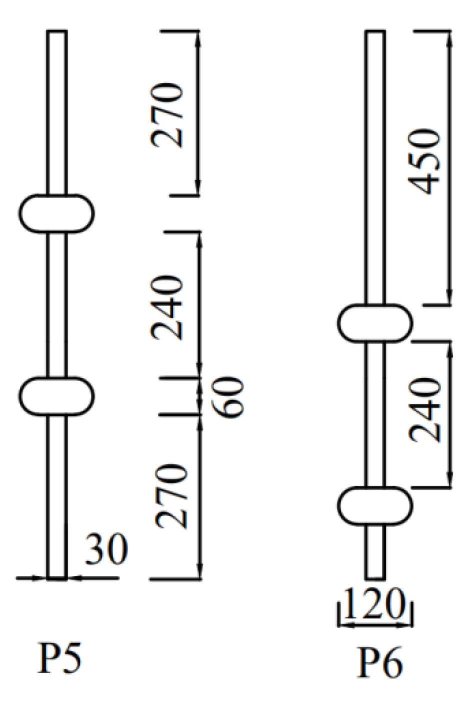
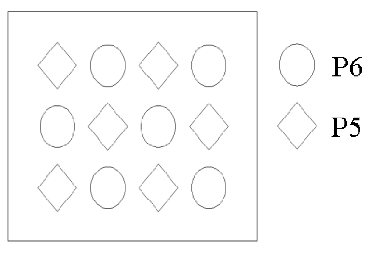
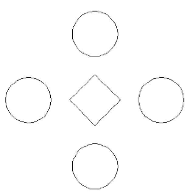
2.3. Equal-Section Pile and Nodular Pile

Based on the similarity of elastic modulus of the materials used under laboratory and real conditions and comprehensively considering the experimental material’s ease of processing, low economic cost, and stability, aluminum pipe is selected as the material of model pile. The size of model pile is 30 mm in diameter, 3 mm in wall thickness, 1000 mm in length, and 900 mm in effective length. The material of the expanding part is nylon resin. The height and diameter of the expanding part are 60 mm and 120 mm respectively. In order to increase the friction coefficient between pile and soil, the surface of aluminum pile was coarsened by a small hacksaw. A reserved hole with a radius of 5 mm is reserved near the pile body, which is used as the passage of foil gauge wire. Figure 7 presents the detailed configuration of pile.

2.4. Sand

River sand passing the 1 mm and 0.1 mm standard sieves were taken as the foundation soil for this test. The maximum and minimum dry bulk densities of the sand were 16.30 kN/m3 and 13.70 kN/m3 respectively, and the corresponding values of minimum void ratio and maximum void ratio were 0.35 and 0.28 respectively. The moisture content was 21.5%, the specific gravity was 2.66, the average particle size was 0.21 mm, the effective particle size was 0.11 mm, the nonuniform coefficient was 2.35, the curvature coefficient was 0.82, the cohesion was 4 kPa, and the internal friction angle was 30° [22].

2.5. Test Procedure

Prior to soil filling, lines with equal spacing were marked on the inner wall of the model box to ensure that soil was filled and impacted layer by layer. The relative compactness of each soil layer was 0.67. The pile was embedded into the soil at designed depth during soil filling.
The portal-rigid frame with two columns was used to apply the reaction force to the pile. The column footings were anchored to rigid ground via anchor rod to ensure the stability of the steel frame. Holes drilled on the steel column from top to bottom allowed to adjust the height of the loading system to meet the actual loading requirements.
The vertical displacement of the pile was measured by a numerical control displacement sensor with an accuracy of 0.01 mm. The fixed bracket was placed at the edge of the model box, and the magnetic base was attached to the extension arm of the fixed support. Finally, the displacement sensor was installed (Figure 7).
Loading scheme of model test was as follows: according to technical code for testing of building pile foundation, the load was applied by manual pressure pump stage by stage. As the requirements, the next stage load can only be applied unless the settlement becomes stable. The readings were recorded once every 15 min within the first hour and every 30 min within the second hour, and every 1 h after 2 h. If the settlement at a certain loading stage is less than 0.1 mm within 30 min, the settlement can be regarded as stable and the next loading stage can be applied.
Criteria for ultimate load: (1) If at the ith loading stage, the total settlement Δhi ≥ 40 mm, or the Δhi is greater than or equal to 5 times of Δhi−1, the test can be terminated and the load at the (i−1)th stage is taken as the ultimate load; (2) if at the ith loading stage, the total settlement Δhi < 50 mm but the settlement fails to reach a stable state after 24 h, the load test can also be terminated and the load at the (i−1)th stage is taken as the ultimate load.
Parameters of piles are listed in Table 1. P1 is the equal-section pile and others are expanded piles. P2–P4 have single nodular part and P5–P7 have two nodular parts. In this paper, the differences in axial force curve and load settlement curve of equal-section pile and nodular piles were compared. Those curves of nodular piles with single and two nodular parts were also compared. In addition, the influence of the position of the nodular part on the ultimate bearing capacity and axial force of the pile body were studied.

3. Results and Discussions

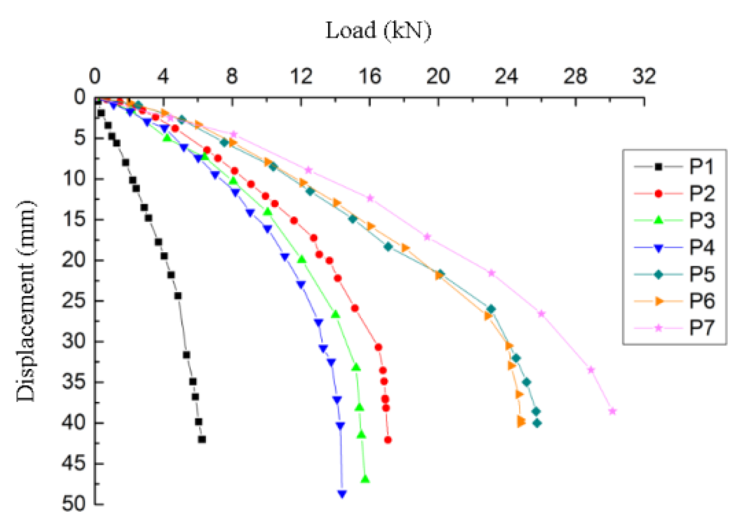
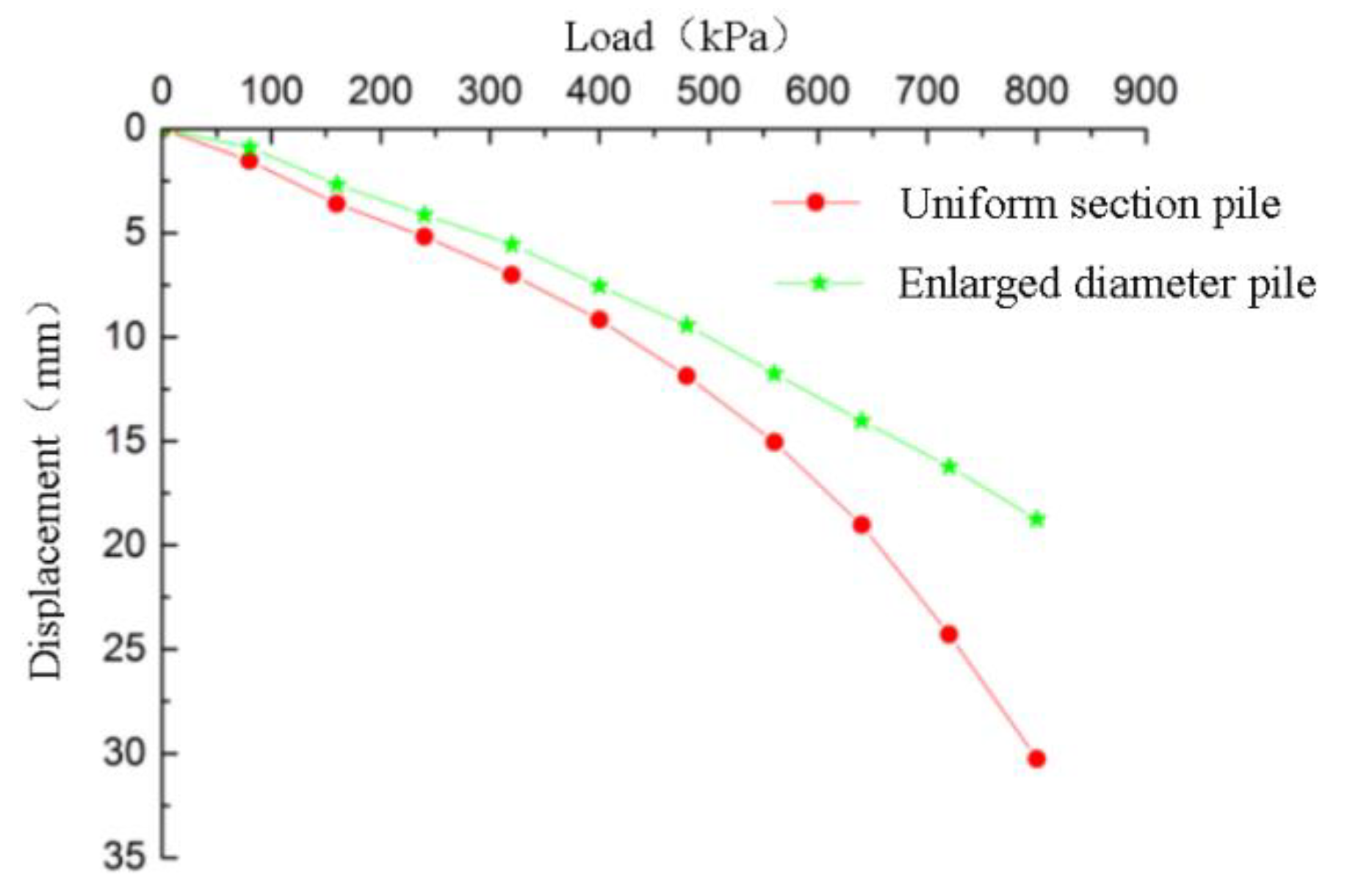
3.1. Load Displacement Curve

The load settlement curves of all piles are shown in Figure 8.
As can be seen from Figure 8, the ultimate bearing capacity of P1 pile is the lowest, while the ultimate bearing capacity of P2 nodular pile reaches 14.4 kN, which is three times that of P1 pile. For P7 with two nodular parts, it has approximately seven times bearing capacity of P1 pile. This illustrates that the nodular piles have much greater bearing capacity than equal-section pile. Besides, the ultimate bearing capacity of piles with two nodular parts are obviously greater than those of piles with single nodular part, indicating that increasing number of nodular parts helps increase the ultimate bearing capacity of nodular piles. It is noticeable that the ultimate load of P7 pile is about 30% higher than that of P5 and P6 piles, which indicates that the distance between the two nodular parts is the key factor affecting the bearing capacity of piles with double nodular parts [23].
Under the same load, the settlement of nodular pile is obviously lower than that of the equal-section pile. The trend of load settlement curve of P2–P4 piles are similar, which indicates that the position of nodular part has little influence on the ultimate load of single nodular piles. This is also verified by P5 and P6 piles, which have almost the same settlement under same vertical load. For P7 pile with larger distance between nodular parts than P5 and P6, a smaller settlement is observed. When the distance is large, the nodular parts allows the soil between them to give full play to the shear capacity. When the distance is small to a certain range, shear failure tends to occur in the soil body between the nodular parts, and thus the shear capacity of the soil body might be severely damaged.

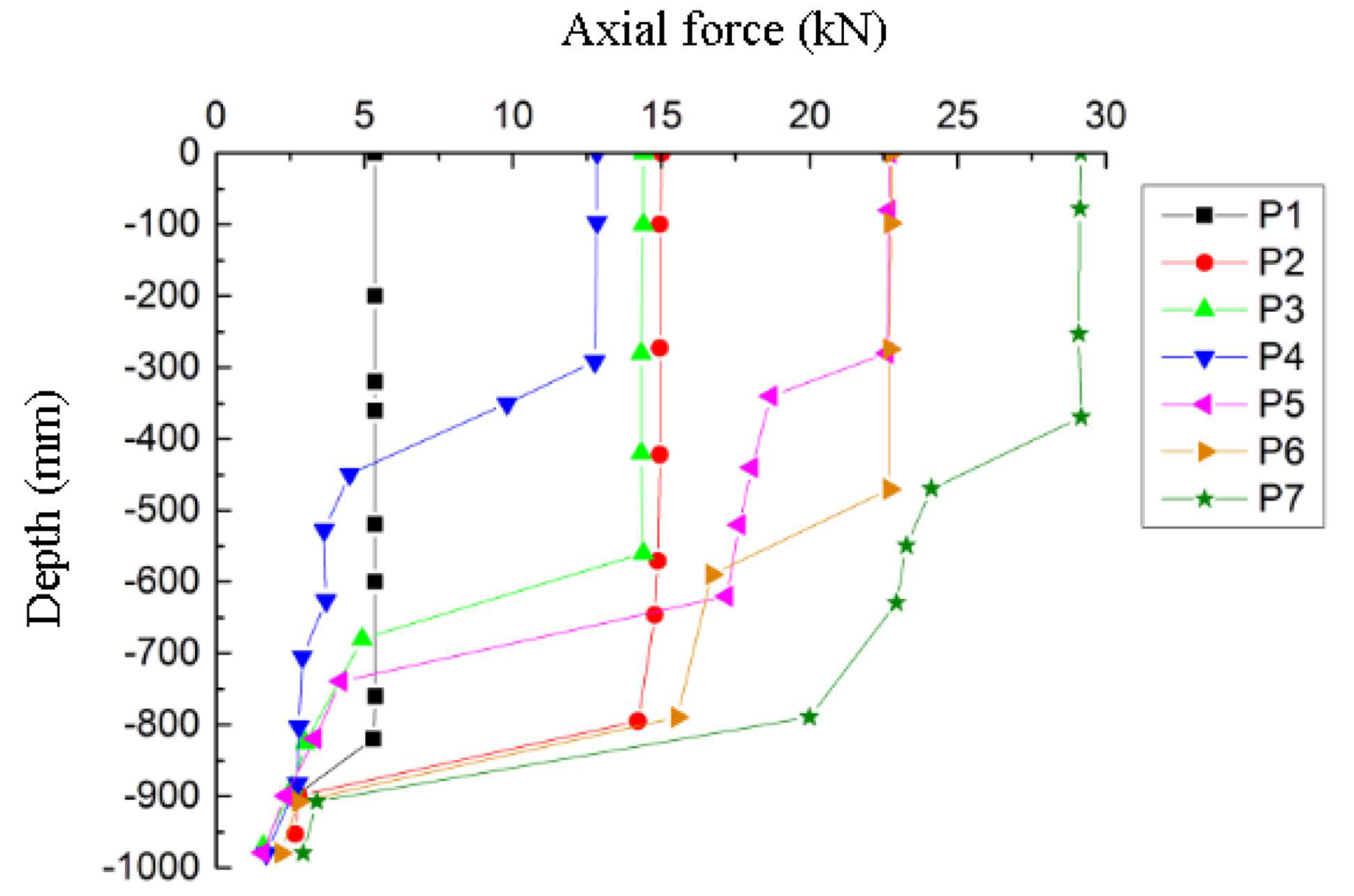
3.2. Axial Force Analysis of Monopile

The distribution of axial force along the pile body of seven types of piles is plotted in Figure 9. The data collection of axial force along the pile body is summarized in Table 2.
It can be seen from Figure 9 that the axial force of equal-section pile P1 keeps almost constant along the pile body until it drops sharply near the pile end. The friction coefficient between the aluminum pile and sandy soil is very small, thus the side friction force along the pile is very small. For this reason, the axial force transfer curves of the equal section pile and the axial force curve of nodular piles above the nodular parts are nearly straight lines.
However, for piles with single nodular part (P2–P4), one inflection point can be found on the axial force curves and for piles with two nodular parts (P5–P7), two corresponding inflection points can be observed. It can be seen that the depth of inflection point is well related to the depth of nodular parts, which indicates that the axial force suddenly changes at the nodular part. The reason for this phenomenon is that the nodular part can transfer most of the load to the soil under the nodular part of the pile, which can give full play to the bearing capacity of the soil under the nodular part.
From the axial force transfer curve of P2–P4 piles, it can be seen that during the loading process, the nodular part squeezes the soil layer below and in return, the pile subjects to greater lateral force from the soil under the nodular part. As a result, the side friction resistance increases and the axial force reduces at the depth below nodular part.
Nodular pile P5 and P6 have approximate difference of axial force at the upper and lower section of nodular part because they have the same distance, i.e., the same soil thickness between nodular parts. The thicker soil layer between the nodular parts of P7 pile holds more load, thus the difference of axial force at the upper and lower section of nodular part is much greater.
Axial force reduction below the depth of first nodular part of pile with double nodular parts is more significant than that of pile with single nodular part. When the soil between the two nodular parts is squeezed by the vertical load, the lower nodular part hinders the downward movement of the soil, resulting in greater pressure on this part of the soil. Therefore, the lateral reaction force at this section is larger than that of the single nodular part pile, and the side friction resistance of this part is relatively larger. Therefore, the reduction of axial force at this part of pile with double nodulars is larger than that of the single nodular part pile.

4. Simulations

In order to test that the foundation consolidated by the vortex-compression nodular pile can improve the bearing capacity and reduce the settlement, the influence of different loads, pile modulus, modulus of soil around pile, cushion modulus, and cushion thickness on the pile-soil stress ratio and settlement of the complexes foundation were studied and analyzed. The finite element analysis was carried out by ABAQUS software [24,25,26].

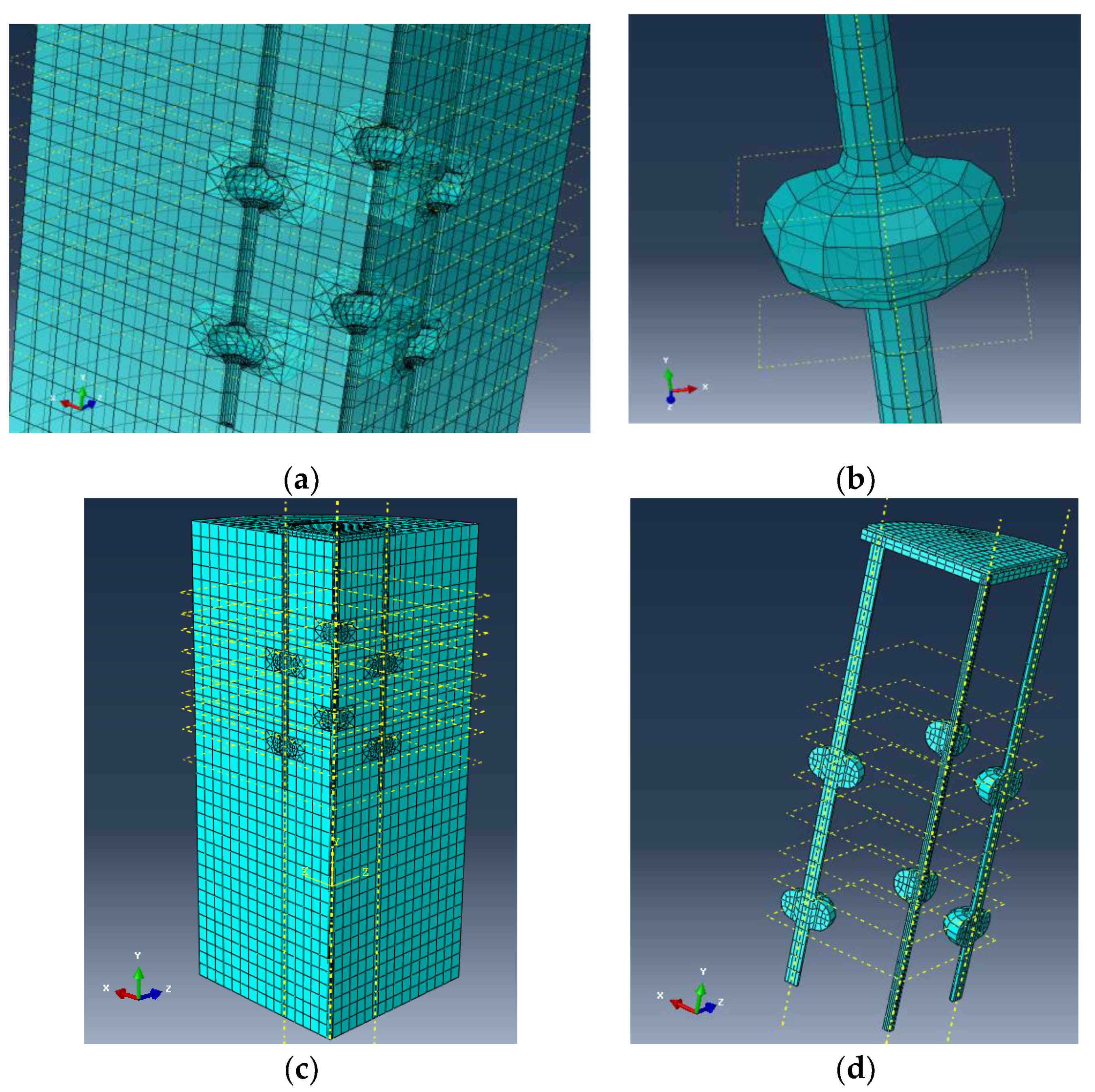
4.1. Finite Element Model Description

P5 pile and P6 pile were used for finite element simulation. Their geometric scheme is shown in Figure 10. The P5 and P6 were embedded alternatively, as shown in Figure 11. The selected numerical simulation unit is shown in Figure 12. According to Figure 12, the numerical simulation model is an axisymmetric model. In order to improve computation efficiency, a quarter of the model is selected for analysis. As the assumptions, the soil around the pile and the cushion conform the ideal elastic-plastic model and the Mohr Coulomb model is adopted. The pile and loading plate are described with linear elastic model. The research scope of the model is: 10 times of pile diameter in radial direction, twice of pile length in depth, and 0.28 m in cushion diameter.
(1) Element selection: eight node linear hexahedron element (C3D8R) is adopted for each component, and the reduced integral is selected, which can prevent sand leakage. Ten node quadric tetrahedral element (C3D10) is used in local parts. The straight section of the pile is roughly divided into units. The nodular part and the contact area around nodular part are finely divided into units. Finally, the whole model is divided into 18031 units. See Figure 13 for the grid division results.
(2) Material parameters: It is assumed that the soil around the pile is homogeneous. The elastic modulus of soil around the pile is 20 MPa, the modulus of loading plate is 40 GPa, the thickness of cushion is 30 mm, the elastic modulus of cushion is 80 MPa, and the elastic modulus of pile is 30 GPa.
(3) Constraint conditions: The soil around the pile is set as a cylindrical boundary, and the Y direction is the vertical direction of the model. X and Z-direction constraints are set on the side of soil, fixed constraints in X, Y, and Z directions are set on the foundation soil surface, the X-direction and Z-direction constraints are set on the two sides of the soil. Before balancing the ground stress of the soil, the X and Z-direction constraints are set at the contact surface between the soil and the pile, and the constraints are deleted after the balance. Before balancing the ground stress of the pile, three directions of constraints are set on the pile, the X and Z-direction constraints are set on the pile after the balance. The cushion and loading plate are deleted in the analysis step of balancing ground stress. After the balance, the cushion and loading plate are restored, and the X and Z-direction constraints are set on the side of the cushion and loading plate.
(4) Contact model: The contact between pile and soil conforms to Coulomb friction contact model with the friction coefficient of 0.4. Hard contact model is adopted for pile top and cushion contact, cushion and soil around pile contact, cushion and loading plate contact.
(5) Load application: The vertical load is directly applied on the loading plate in ten stages and the load increment of each stage is 80 kPa. Unloading process is not considered in this paper.
(6) Ground stress balance: Balancing the initial ground stress is a very important step in this model. The simulation of pile-soil interaction must be considered. The soil weight in this model is set as the initial stress. The upper surface of the model soil is plane, so ground stress balance can be done by ABAQUS software. The displacement after balance reaches 10−9 orders of magnitude, and the balance effect is very good.

4.2. Comparison of Bearing Capacity of Equal-Section Pile Foundation and Vortex-Compression Nodular Pile Foundation

The modeling process of equal-section pile foundation and vortex-compression nodular pile foundation are the same. The pile spacing is three times of pile diameter, and the physical parameters of soil and pile are the same. The vertical stress and displacement two kinds of foundation are extracted from the simulation results, as shown in Figure 14.
It can be seen from Figure 14 that the settlement of equal-section pile foundation is larger under the same load. The curve of complexes foundation with constant cross-section pile is steep, while that of complexes foundation with enlarged diameter pile is smooth. With the increase of the load, the settlement difference between the two complexes foundations becomes larger and larger, which fully shows that the foundation treated by dislocation vortex compression pile has good settlement reduction and greater bearing capacity [27].

4.3. Simulation Analysis of Influencing Factors on Bearing Characteristics of Vortex-Compression Nodular Pile Foundation

4.3.1. Analysis of Influence of Load on Bearing Characteristics

The thickness of cushion is 30 mm. The elastic modulus of soil around the pile is 80 MPa, the modulus of loading plate is 40 GPa, the elastic modulus of cushion is 80 MPa, and the elastic modulus of pile is 30 GPa. The stress nephogram and displacement nephogram under 800 kPa load are shown in Figure 15 and Figure 16.
According to the results of numerical analysis, the ratios of vertical stress at top of P5 pile and at adjacent soil under different loads are drawn, in Figure 17.
It can be seen from Figure 17 that the pile-soil vertical stress ratio increases with the increase of load. When the load is small, the soil deformation is in the elastic stage, the pile-soil stress ratio is small. The bearing capacity of the soil around the pile works well where, the cushion plays an active role. The stress distribution is normal and uniform. Besides, when the load is small, the friction resistance at the top of pile is negative under the action of cushion, which helps to reduce the deformation and improve the bearing capacity [28]. When the load exceeds 400 kPa, the pile-soil stress ratio increases obviously with the increase of load. At this time, the regulating effect of cushion is obviously weakened, and the stress concentrates upon the top of the pile. Finally, the plastic failure of cushion at pile top occurs.

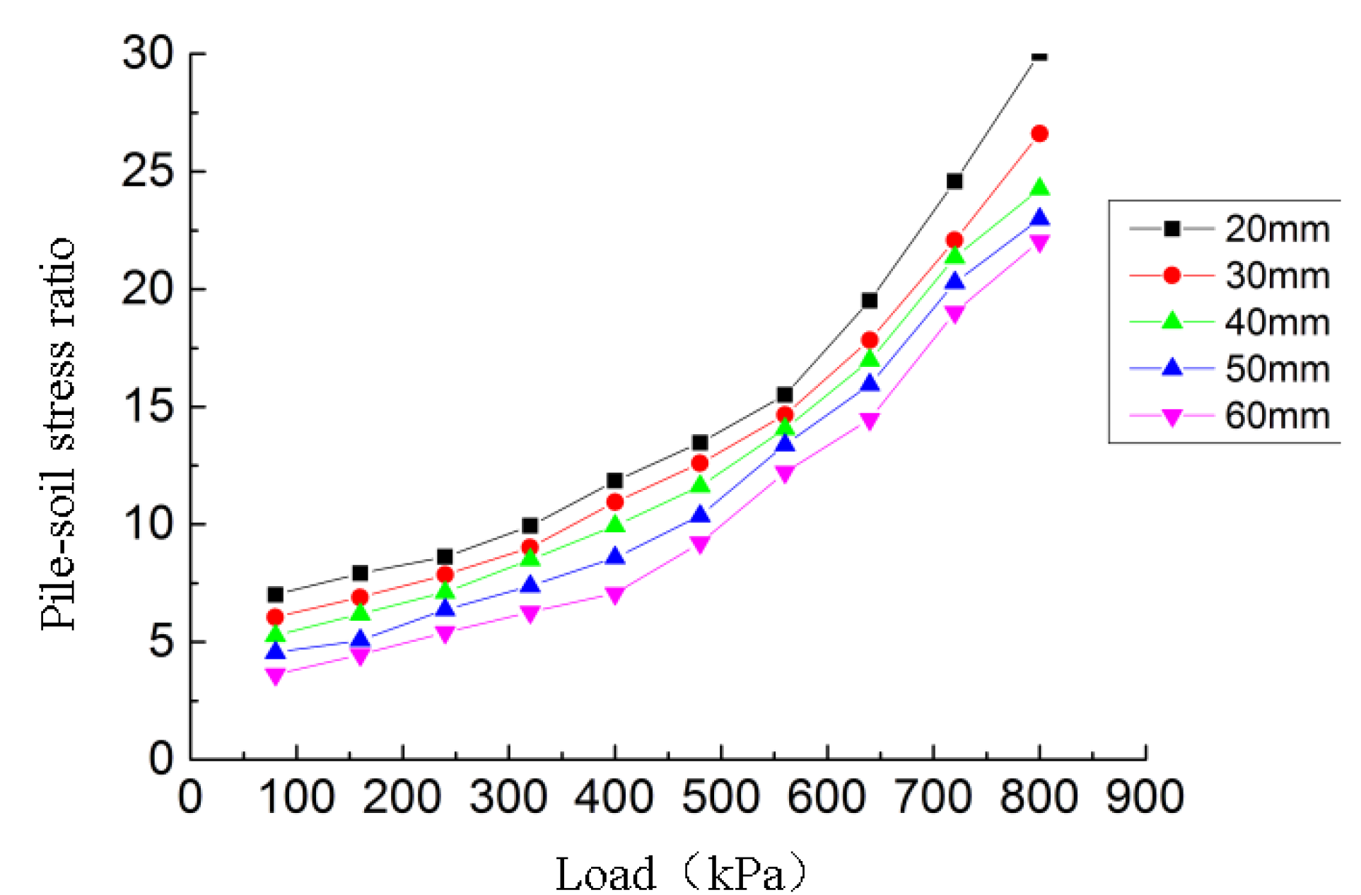
4.3.2. Analysis of influence of Cushion Thickness on Bearing Capacity

Cushion is the essential part of composite foundation, which can share part of the upper load to the soil around the pile and allow the surrounding soil to give full play of the bearing capacity. For this reason, it can greatly reduce the settlement and avoid the damage caused by the stress concentration of the pile top on the upper components [29]. The influence of cushion thickness on settlement is shown in Figure 18.
It can be seen from Figure 18 that for a constant cushion thickness, the settlement increases with the increase of the load. Under the constant vertical load, the settlement decreases as the cushion thickness increases from 20 mm to 30 mm. At this time, the bearing capacity of the soil between piles is fully played, and the stress is well distributed. However, further increasing the cushion thickness will lead to a larger settlement. In this simulation, the optimum cushion thickness is about 30 mm [30,31].
Figure 19 presents the influence of cushion thickness on pile-soil stress ratio. The trend of five curves with different thickness is approximately the same. The pile-soil stress ratio increases linearly under small loads. When the load reaches 320 kPa, the pile-soil stress ratio increases sharply and even increases at an exponential rate after the load exceeds 560 kPa. Under the same load, the thicker the cushion is, the smaller the pile-soil stress ratio is and greater the bearing capacity of the soil around the pile is. However, considering the influence of cushion thickness on settlement, a thicker cushion is not always favorable in practical applications. In other words, the effect of cushion thickness on settlement and pile-soil stress ratio should be considered at the same time. The thickness of cushion should be reasonably selected so as to maximize the bearing capacity of soil around the pile and adjust the reasonable stress distribution on the pile and the soil around the pile.

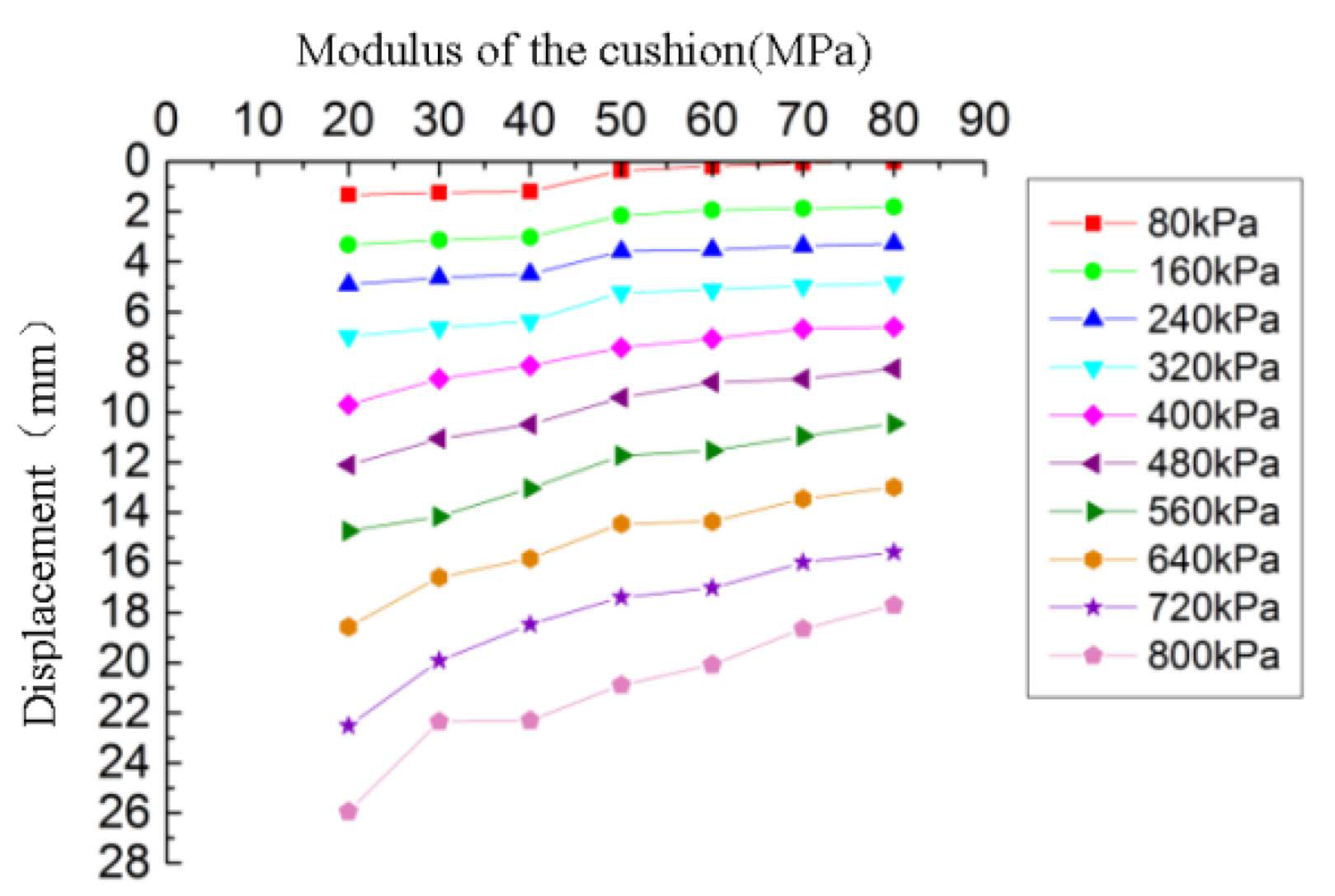
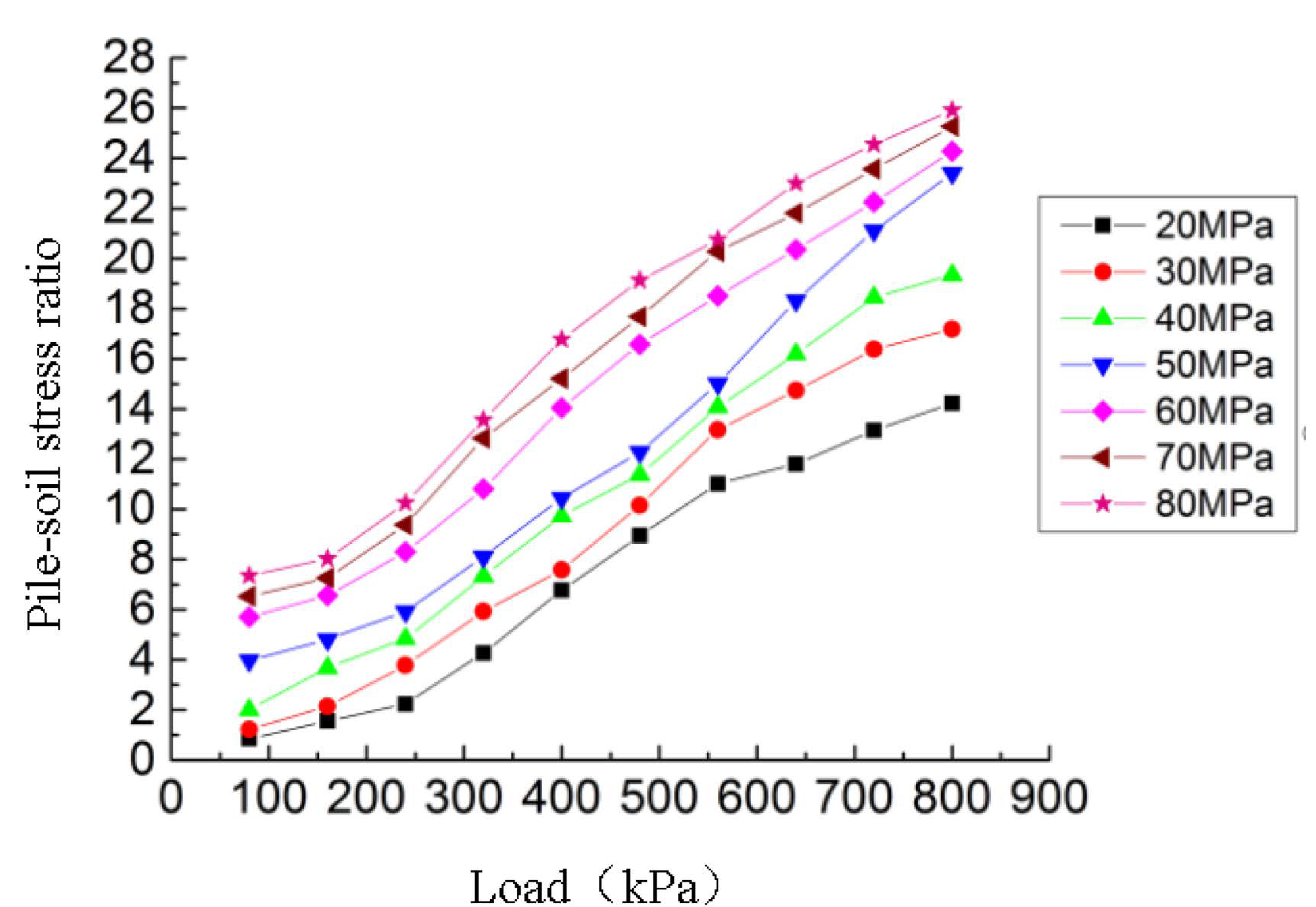
4.3.3. Influence Analysis of Cushion Modulus on Bearing Capacity

The thickness of cushion is 30 mm. The elastic modulus of soil around the pile is 80 MPa, the modulus of loading plate is 40 GPa, and the elastic modulus of pile is 30 GPa. The influence of cushion modulus on settlement is shown in Figure 20.
It can be seen from Figure 20 that the settlement decreases with the increase of cushion modulus under the same load. The reason is that the increase of the cushion modulus is more likely to cause stress concentration on the pile top. The cushion transfers most of the load to the vortex-compression nodular pile, hence, the load shared by the soil is small. The nodular pile plays an excellent role in settlement reduction. The difference between the settlement of pile and the soil around the pile tends to be stable, so the overall settlement is reduced. With the increase of load, the influence of cushion modulus on settlement becomes more obvious.
According to Figure 21, the seven curves with different modulus share approximately the same trend. Under the same load, the greater the cushion modulus is, the greater the pile-soil stress ratio is, and the smaller the coefficient of bearing capacity of soil around the pile is. The reason behind this is that the increase of cushion modulus leads to the stress concentration at the pile top. The fluidity of cushion material decreases, thus the gap between pile and soil around pile cannot be filled in time, and the squeezing effect on soil is reduced. In practical application, it is necessary to select a moderate cushion modulus to reduce the settlement and increase the pile-soil stress ratio meanwhile.

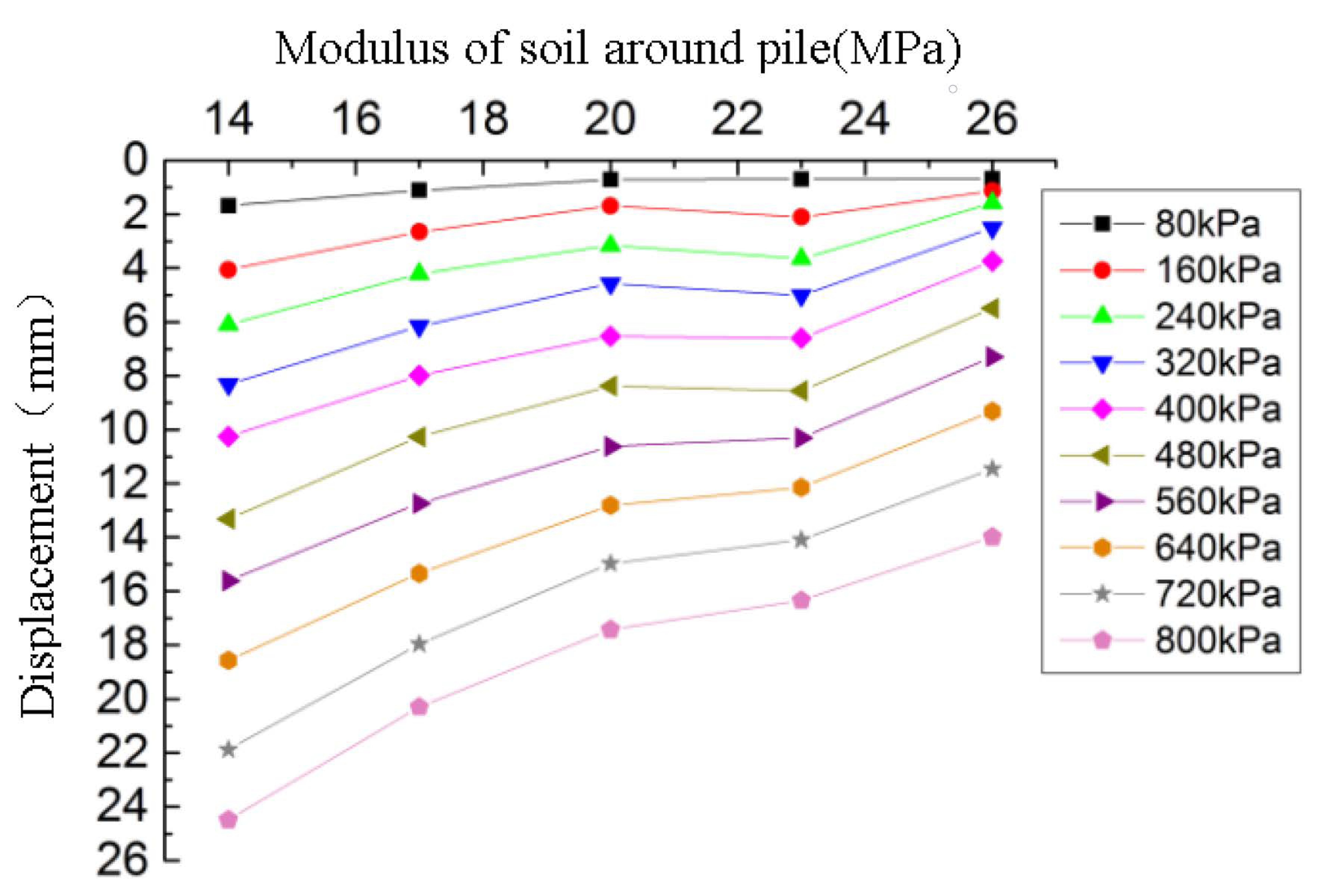
4.3.4. Influence Analysis of Modulus of Soil Around Pile on Bearing Characteristics

The influence of elastic modulus of soil around the pile on settlement is shown in Figure 22.
It can be seen from Figure 22 that under the same load, the settlement decreases gradually with the increase of modulus of soil around the pile. As the modulus of soil around the pile increases, the soil is more difficult to be compressed and the settlement is smaller. In addition, the soil at the pile end is not easy to be compressed, resulting in the decrease of pile settlement. Under greater load, this effect is more obvious.
As shown in Figure 23, when the modulus of soil around the pile is constant, the pile-soil stress ratio first increases rapidly and then slowly with the increase of load. Under the same load, the greater the soil modulus, the smaller the pile-soil stress ratio is. With the increase of the modulus of soil around the pile, the compressive resistance of the cushion to the soil around the pile increases and the settlement of the soil decreases, hence the soil around the pile shares more load.

4.3.5. Influence Analysis of Pile Modulus on Bearing Characteristics

The influence of pile modulus on model settlement and pile-soil stress ratio are shown in Figure 24 and Figure 25, respectively.
Under small load, the change of pile modulus has little effect on settlement. Even when the load reaches 800 kPa, the settlement decreases by only 2.1 mm. Similarly, it can be seen from Figure 25 that the pile-soil stress ratio slightly increases with the increase of pile modulus. The results show that the pile modulus has little effect on the settlement and pile-soil stress ratio.

5. Conclusions

Through the indoor model test, the bearing capacity of the vortex-compression nodular piles and equal-section piles are compared. The curve of axial force distribution along the pile body and the load-settlement curve of the pile are mainly studied. Through the finite element simulation, the effect of parameters on bearing characteristics of composite foundation with vortex-compression nodular piles are analyzed [32,33]. The following conclusions can be drawn from this paper.
The results show that, compared with equal-section pile foundation, the vortex-compression nodular piles foundation has superior bearing capacity, slighter settlement, and gentler settlement changes with the load. The position of nodular part has little influence on the bearing capacity of nodular piles with single or double nodular parts. Nevertheless, the bearing capacity of vortex-compression nodular piles increases with the increase of the distance between the two nodular parts.
The settlement is positively correlated with the load but negatively correlated with the modulus of the cushion and the modulus of the soil around the pile. The settlement decreases but then increases with the increase of cushion thickness. The pile-soil stress ratio is positively correlated with the load and the cushion modulus but is negatively correlated with the cushion thickness, and soil modulus.
In practical application, the influence of cushion thickness and cushion modulus on settlement and pile-soil stress ratio should be comprehensively considered, and appropriate cushion thickness and modulus should be selected.

Author Contributions

C.-B.L. conceived the study. C.-B.L. and G.-J.L. carried out the case study. R.-G.Y. supervised the study. G.-J.L. and X.-S.M. collected and analyzed the data. C.-B.L. edited the manuscript. J.L. provided some suggestion for the manuscript editing. All authors have read and agreed to the published version of the manuscript.

Funding

The research was carried out in the general project “Study on quantitative prediction of fractures in tight reservoirs under the coupling action of thermal, fluid, solid, and creep” (project number 4197-2138) kindly supported by The National Natural Science Foundation of China.

Acknowledgments

We kindly thank Research Center of Civil Engineering, China University of Petroleum (East China) for providing laboratory facilities and experimental devices.

Conflicts of Interest

The authors declare no conflict of interest.

References

  1. Fang, P.F.; Xie, X.Y.; Qi, J.L. Engineering character of a new-style pretensioned spun goncrete nodular Pile. Geo Shanghai 2014. [Google Scholar] [CrossRef]
  2. Pavan, K.T.; Papa, R.G.; Veerabhadra, R.P. Comparative study of different foundation and sidewall systems for large storage tanks. In Recent Advances in Structural Engineering; Springer: Berlin/Heidelberg, Germany, 2019; Volume 1, pp. 193–205. [Google Scholar]
  3. Chen, L.H.; Liu, X.L. Reasonable selection of tank foundation consolidation method. Petrol. Plan. Des. 2005, 16, 44–45. [Google Scholar]
  4. Zhang, J.W. Discussion on several problems on poor foundation consolidation of large storage tank (To be continued). Petrol. Eng. Constr. 2002, 28, 6–10. [Google Scholar]
  5. Zhang, S.; Zhao, M.; He, L.; Zhang, L. Calculation of settlement of composite foundation with rigid piles under flexible ground. J. Highway Transp. Res. Dev. 2013, 5, 15–21. [Google Scholar] [CrossRef]
  6. Lin, P. Foundation consolidation of large oil tank by gravel pile. Guangdong Chem. 2013, 40, 134–141. [Google Scholar]
  7. Jia, J.H. Study on Working Behavior of Gravel Pile Composite Foundation of Large Storage Tank; Hebei Agricultural University: Baoding, China, 2009. [Google Scholar]
  8. Dong, H.B. Experimental Study on CFG Pile Composite Foundation in Foundation Consolidation of Large Storage Tank; China University of Petroleum: Qingdao, China, 2007. [Google Scholar]
  9. Song, X.G. Study on Bearing Behavior of CFG Pile Composite Foundation in Saturated Loess Foundation Consolidation of Large Oil Tank; Lanzhou Jiaotong University: Lanzhou, China, 2008. [Google Scholar]
  10. Li, P. Finite Element Numerical Analysis of Deformation Behavior of Gravel Pile Composite Foundation for Large Oil Storage Tank; Ocean University of China: Qingdao, China, 2010. [Google Scholar]
  11. Liu, H.J.; Shi, X.R.; Wang, X.H. Finite element numerical analysis on differential settlement of composite foundation of storage tank group. Qingdao J. Ocean Univ. China (Soc. Sci.) 2016, 46, 117–123. [Google Scholar]
  12. Li, C.B.; Xue, S.F.; Liu, X.H. Pile Forming Equipment and Method for Vortex Compression Nodular Piles. China: ZL2014101136668, 2014-12-10. CN103835289A. Available online: https://kns.cnki.net/kcms/detail/detail.aspx?dbcode=SCPD&dbname=SCPD2014&filename=CN103835289A&v=Rim3ylsWTszpRhbAHJM8PCMN4h9FqLKSUo9oW%25mmd2FVzLe51UlegvfT5uKGWJfZf8CJl (accessed on 10 October 2020).
  13. Li, C.B.; Xue, S.F.; Yu, R.G.; Zhang, Y.M.; Sun, X.; Liu, X.H.; Zhao, Z.J. Laboratory experimental study on the application of vortex compression equipment in foundation consolidation. J. Chongqing Jianzhu Univ. 2014, 36, 78–81. [Google Scholar]
  14. Li, C.B.; Xue, S.F.; Yu, R.G.; Zhang, Y.M.; Zhang, M.; Liu, X.H.; Zhao, Z.J. Mechanism of vortex squeezing expansion and its application in geotechnical engineering. Forest Eng. 2014, 30, 137–140, 146. [Google Scholar] [CrossRef]
  15. Nazir, A. Model study of single pile with wings under uplift loads. Appl. Ocean Res. 2020, 100, 1–17. [Google Scholar]
  16. Chen, Y.D.; Deng, A.; Wang, A.T.; Sun, H.S. Performance of screw—Shaft pile in sand: Model test and DEM simulation. Comput. Geotech. 2018, 104, 118–130. [Google Scholar] [CrossRef]
  17. Sakr, M. Relationship between Installation Torque and Axial Capacities of Helical Piles in Cohesionless Soils. DFI J. Deep Found. Inst. 2015, 7, 44–58. [Google Scholar] [CrossRef]
  18. Houda, M.; Jenck, O.; Emeriault, F. Physical evidence of the effect of vertical cyclic loading on soil improvement by rigid piles: A small-scale laboratory experiment using Digital Image Correlation. Acta Geotech. 2016, 11, 325–346. [Google Scholar] [CrossRef]
  19. Meng, Z.; Chen, J.J.; Wang, J.H. Numerical analysis of bearing capacity of drilled displacement piles with a screw-shaped shaft in sand. Marine Geotechnol. 2016, 661–669. [Google Scholar] [CrossRef]
  20. Ye, X.; Wang, S.; Wang, Q.; Sloan, S.W.; Sheng, D.C. Numerical and experimental studies of the mechanical behaviour for compaction grouted soil nails in sandy soil. Comput. Geotech. 2017, 90, 202–214. [Google Scholar] [CrossRef]
  21. Fu, Z.; Chen, S.; Liu, S. Discrete Element Simulations of Shallow Plate-Load Tests. Int. J. Geomech. 2016, 16, 04015077.1–04015077.12. [Google Scholar] [CrossRef]
  22. Nabizadeh, F.; Choobbasti, A.J. Field Study of Capacity Helical Piles in Sand and Silty Clay. Transp. Infrastruct. Geotechnol. 2016, 4, 1–15. [Google Scholar] [CrossRef]
  23. Shoda, D.; Kawabata, T.; Uchida, K. Mechanical Behavior on Pile with Multi-Stepped Two Diameters under Combined Load; Transactions of The Japanese Society of Irrigation, Drainage and Rural Engineering: Tokyo, Japan; Minato-ku, Japan, 2011; Volume 78, pp. 157–165. [Google Scholar]
  24. Mendoza, C.C.; Cunha, R.; Lizcano, A. Mechanical and numerical behavior of groups of screw (type) piles founded in a tropical soil of the Midwestern Brazil. Comput. Geotech. 2015, 67, 187–203. [Google Scholar] [CrossRef]
  25. Aoyama, S.; Mao, W.; Goto, S.; Towhata, I. Application of Advanced Procedures to Model Tests on the Subsoil Behavior Under Vertical Loading of Group Pile in Sand. Ind. Geotech. J. 2015, 46, 1–13. [Google Scholar] [CrossRef]
  26. Khazaei, J.; Eslami, A. Postgrouted helical piles behavior through physical modeling by FCV. Marine Geotechnol. 2016, 35, 528–537. [Google Scholar] [CrossRef]
  27. Rahman, M.A.; Sengupta, S. Uplift Capacity of Inclined Underreamed Piles Subjected to Vertical Load. J. Inst. Eng. 2017, 98, 533–544. [Google Scholar] [CrossRef]
  28. Long, J.; Zhao, M.; Zhang, L.; Zhang, G.B. Pile-soil Stress Ratio of Pile-supported and Geogird-reinforced Composite Foundation. J. Highway Transp. Res. Dev. 2010, 6, 18–23. [Google Scholar] [CrossRef]
  29. Liu, K.; Xie, X.; Shi, S.; Zhu, X. Numerical Analysis on the Performance of a Cushioned Foundation with a Mixture of Both Rigid and Flexible Piles. In Proceedings of the US-China Workshop on Ground Improvement Technologies, Orlando, FL, USA, 14 March 2009. [Google Scholar]
  30. Ferrantelli, A.; Fadejev, J.; Kurnitski, J. Energy Pile Field Simulation in Large Buildings: Validation of Surface Boundary Assumptions. Energies 2019, 12, 770. [Google Scholar] [CrossRef] [Green Version]
  31. Gao, L.; Han, C.; Xu, Z.; Jin, Y.; Yan, J. Experimental Study on Deformation Monitoring of Bored Pile Based on BOTDR. Appl. Sci. 2019, 9, 2435. [Google Scholar] [CrossRef] [Green Version]
  32. Prendergast, L.J.; Gandina, P.; Gavin, K. Factors Influencing the Prediction of Pile Driveability Using CPT-Based Approaches. Energies 2020, 13, 3128. [Google Scholar] [CrossRef]
  33. Baca, M.; Brząkała, W.; Rybak, J. Bi-Directional Static Load Tests of Pile Models. Appl. Sci. 2020, 10, 5492. [Google Scholar] [CrossRef]
Figure 1. Pile forming mold and structure diagram of the nodular pile: (a) side view; (b) overhead view.
Energies 13 05273 g001
Figure 2. Working principle diagram of pile forming mold.
Energies 13 05273 g002
Figure 3. Pile forming equipment of the nodular pile: (a) schematic diagram of pile frame; (b) schematic diagram of vortex-compression steel pipe; (c) physical drawing of vortex-compression chamber; (d) 3D diagram of vortex-compression blade; (e) 3D drawing of precast concrete pile head; (f) plan of knob gear.
Energies 13 05273 g003
Figure 4. The process of construction technology of nodular piles.
Energies 13 05273 g004
Figure 5. Model box: (a) physical drawing of model box; and (b) model box drainage system.
Energies 13 05273 g005
Figure 6. Dial indicator layout scheme.
Energies 13 05273 g006
Figure 7. Typical pile structure: (a) P-1 equal-section pile; and (b) P-7 nodular pile.
Energies 13 05273 g007
Figure 8. Load-displacement curve of seven kinds of pile under vertical load.
Energies 13 05273 g008
Figure 9. Axial force transfer curve of seven kinds of pile under the ultimate vertical load.
Energies 13 05273 g009
Figure 10. Geometric scheme of numerical simulation.
Energies 13 05273 g010
Figure 11. Layout scheme of pile type.
Energies 13 05273 g011
Figure 12. Selected unit for numerical simulation.
Energies 13 05273 g012
Figure 13. Grid division and location sketch map of the model: (a) perspective drawing of local grid division of local soil around pile; (b) perspective drawing of grid division of expanding part; (c) 1/4 model parts location diagram; and (d) schematic diagram of pile, cushion, and loading plate.
Energies 13 05273 g013
Figure 14. The load settlement curve of two complexes foundations.
Energies 13 05273 g014
Figure 15. Stress cloud of 800 kPa load.
Energies 13 05273 g015
Figure 16. Displacement contour of 800 kPa load.
Energies 13 05273 g016
Figure 17. The pile-soil vertical stress ratio under different loads.
Energies 13 05273 g017
Figure 18. The thickness of the cushion effect on the curve of settlement.
Energies 13 05273 g018
Figure 19. The thickness of the cushion effect on the pile-soil ratio.
Energies 13 05273 g019
Figure 20. The elastic modulus of the cushion effect on the curve of settlement.
Energies 13 05273 g020
Figure 21. The elastic modulus of the cushion effect on the pile-soil ratio.
Energies 13 05273 g021
Figure 22. The elastic modulus of the soil effect on the curve of settlement.
Energies 13 05273 g022
Figure 23. The elastic modulus of the soil effect on the pile-soil ratio.
Energies 13 05273 g023
Figure 24. The elastic modulus of the pile effect on the curve of settlement.
Energies 13 05273 g024
Figure 25. The elastic modulus of the pile effect the pile-soil ratio.
Energies 13 05273 g025
Table 1. The configuration of nodular piles.
NumberEffective Pile Length (mm)Pile Diameter (mm)Diameter of Nodular Part (mm)Number of Nodular PartBottom Elevation of Nodular Part (mm)Distance Between Nodular Parts (mm)
P190030----
P2900301201−810-
P3900301201−570-
P4900301201−330-
P5900301202−330, −630240
P6900301202−510, −810240
P7900301202−390, −810360
Table 2. The distribution of axial force along the pile body.
NumberPoint 1 Depth (mm), Corresponding Axial Force (kN)Point 2Point 3Point 4Point 5Point 6Point 7
P10, 5.4−200, 5.3−360, 5.3−600, 5.3−760, 5.3−820, 5.3−900, 2.7
P20, 15.0−100, 14.9−420, 14.9−650, 14.7−790, 14.2−900, 2.8−950, 2.7
P30, 14.4−100, 14.3−560, 14.3−680, 4.9−830, 3.0−890, 2.6−970, 1.6
P40, 12.8−100, 12.8−290, 12.8−530, 3.6−700, 2.9−880, 2.7−980, 1.7
P50, 22.7−280, 22.6−340, 18.7−520, 17.6−620, 17.2−740, 4.2−980, 1.6
P60, 22.7−270, 22.7−470, 22.7−590, 16.7−790, 15.6−910, 2.8−980, 2.2
P70, 29.1−370, 29.2−470, 24.1−630, 22.9−790, 20.0−910, 3.4−980, 2.9

