2. Problem Description
Resistance turnout heating is one of the most expensive, yet most often used methods. Availability of energy sources has undoubted advantages. Resistance systems of turnout heating, beside low equipment costs, are characterized by high reliability, which is of huge importance to safety and continuity of train traffic.
In this study, to reduce energy consumption of turnout heating, laboratory testing of rail heating with heat insulated heaters in a climatic chamber was undertaken [
3,
4]. Placement of heat insulation on a rail is shown in
Figure 2. Comparative testing in a climatic chamber was conducted of 60 E1 (UIC-60) rail heating with a 330 W/m resistance heater without heat insulation, with heat conducting heat insulation, and with two heat insulations: heat conducting and heat insulating. The chamber was intensively cooled down to −28 °C from the initial rail web temperature of +20 °C (
Figure 3) [
5]. When the chamber without heat insulation was cooled, the web temperature reached 0 °C after ca. 150 min. The web temperatures of rails wrapped with heat conducting and heat insulating heat insulation were approximately 20 °C greater. Thus, the impact of heat insulation on energy efficiency of heating was substantial. In spite of these efforts, resistance turnout heating generates high operation cost, maintenance, and electricity consumption.
For years, attempts have been made to introduce energy-saving induction heating (IH) of turnouts. Generation of high frequency electricity and its conversion to thermal energy in a ferromagnetic material that is part of a turnout is the essence of induction [
6,
7,
8,
9]. Induction heating of turnouts can raise their temperature by a dozen Centigrades for effective snow melting.
In most IH solutions, a half bridge voltage inverter receives the energy from a full wave rectifier connected to single phase mains. Power MOSFETs used in the inverter assure high frequency operation of the induction heating system. The main factors of success that have contributed to the wide acceptance of this technology are as follows [
8]:
Generation of heat sources inside the workpiece to be heated over very short times
Possibility of concentrating them in specified areas of the workpiece as required by the application
Rational use of electrical energy for heat generation
IH applications use half bridge inverters to feed heating inductors that generate high frequency electromagnetic fields. An electromagnetic wave penetrates the ferromagnetic material to a depth dependent on the current frequency [
6,
8,
10].
where:
Depth of the electromagnetic wave penetration
δ is connected with active power released as heat in the workpiece. There is a dependence between the inductor’s external radius
re and
δ, expressed with the factor
m for the cylindrical inductor [
8]:
where:
Assuming constant resistivity and magnetic permeability, slight increments of thermal energy are demonstrated in
m > 4. Adopting the following rail data [
1]:
ρ = 2.7 × 10
−7 [Ωm],
μ = 100 and the external radius of the inductor
re = 0.001 [m], heating becomes efficient for the frequency
f > 5.5 kHz. This calculation should be treated as an estimate, since constant resistivity and magnetic permeability are assumed and the complicated rail design is not addressed. Current frequency of 20 kHz is adopted for purposes of this testing of resistance heating.
Temperature distribution and effectiveness of turnout heating can be tested by means of numerical analysis, experimental testing in a climatic chamber, and on actual facilities. All the methods are important and can supplement one another in different ways, though one cannot replace another. The numerical method allows for analysis of magnetic field distribution in a rail material and selection of parameters of an effective source of heating. This is very helpful in optimizing the power supply system, shape, and parameters of an inductor, as well as its arrangement in a turnout space.
Experimental testing helps to analyze temperature distribution across turnout elements in specified environment conditions generated in the climatic chamber. This testing addresses heating conditions in 3D space and considers real rail parameters in induction heating, its magnetization characteristic, resistivity, and magnetic permeability dependent on temperature. It should be noted that a standard rail contains 9 different elements and exhibits pearlite structure. Practical verification of heating efficiency is important.
The experimental method of testing in a climatic chamber was adopted for evaluation of induction heating efficiency, whereas we ignored the analytical method [
7,
11,
12]. Efficiency of induction heating was compared to that of the universal resistance heating. Induction heating (IH) uses an innovative technological solution. It consists of installing an inductor in the bottom part of the slide plate, along which the switch-rail travels. The inductor is the source of heat that melts snow or ice on the slide plate’s surface and in the space between the switch-rail and stock-rail. This article compared methods of heating, i.e., RH and IH, in terms of permissible variations of ambient temperature at which both the systems work effectively, dynamics of temperature changes across turnout elements, retention of good tribological properties when the switch-rail is moved, and effective ice removal from the rail surface.
3. Review of Turnout Induction Heating Solutions
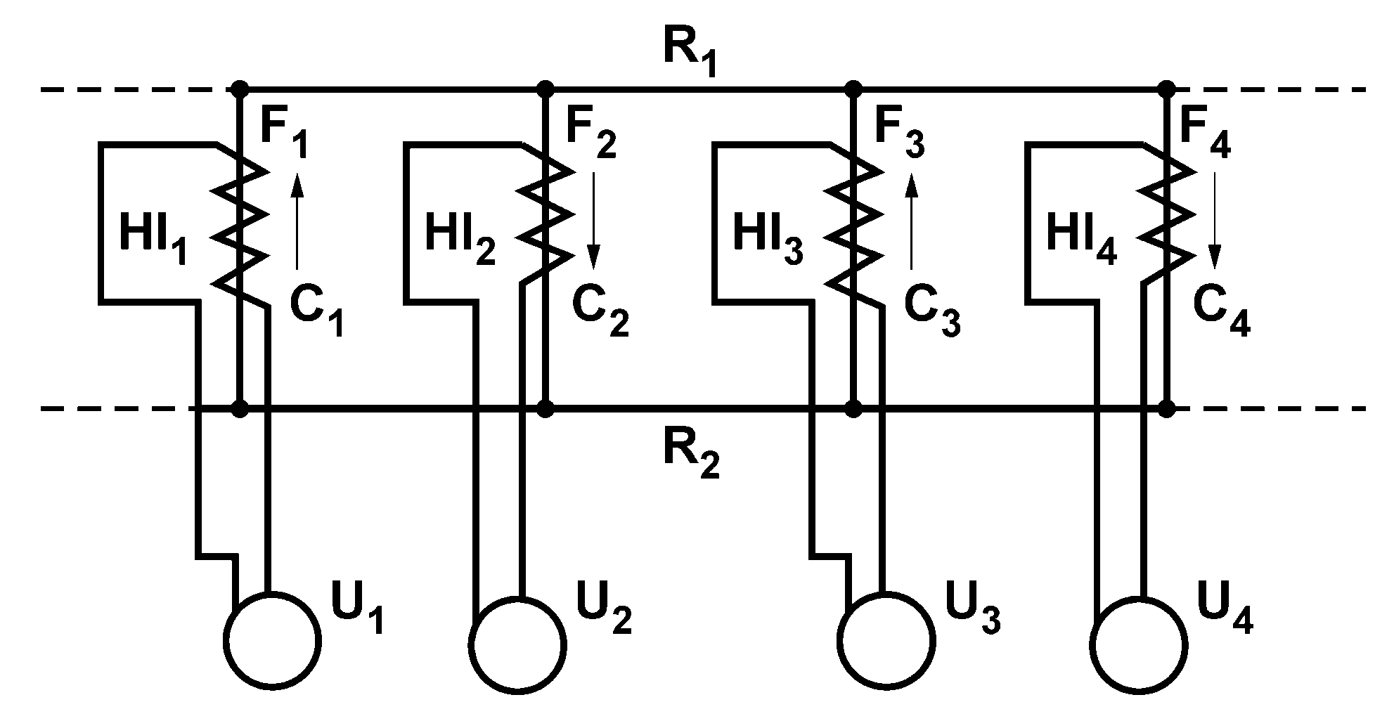
Several equipment solutions based on induction heating have been proposed for the purpose of effective snow removal from turnouts. One of the first is illustrated in
Figure 4 [
13]. Two parallel rails R
1 and R
2 are parts of a magnetic circuit. Heating inductors HI
1, HI
2, HI
3 and HI
4 generate a variable magnetic field penetrating the rails and causing them to heat. The inductors comprise coils C
1, C
2, C
3 or C
4 around the cores F
1, F
2, F
3 and F
4 supplied from sources of alternating voltage U
1, U
2, U
3, or U
4. The arrows along the inductors show senses of magnetic fluxes at a given moment in time. Correct operation of the device requires an even number of the inductors. A magnetic flux penetrating the rails is centered between the paired inductors. Rising numbers of the inductors causes their interactions that may increase the magnetic flux and, consequently, temperature in the middle section of a heated rail.
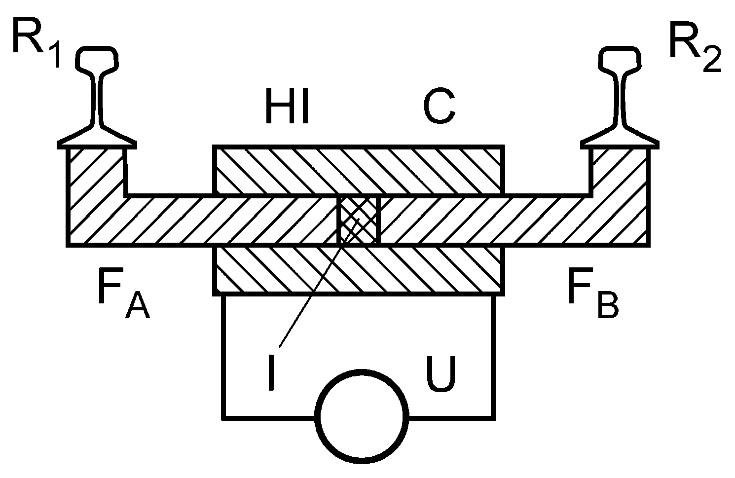
Design of all inductors is identical (
Figure 5). The bottom surfaces of R
1 and R
2 are connected with sections of F
A and F
B and insulation I. C encompasses sections of F
A and F
B and is supplied from U. C produces a variable magnetic flux in sections of F
A and F
B. Sections of the magnetic cores are made of a material reducing energy losses due to eddy currents.
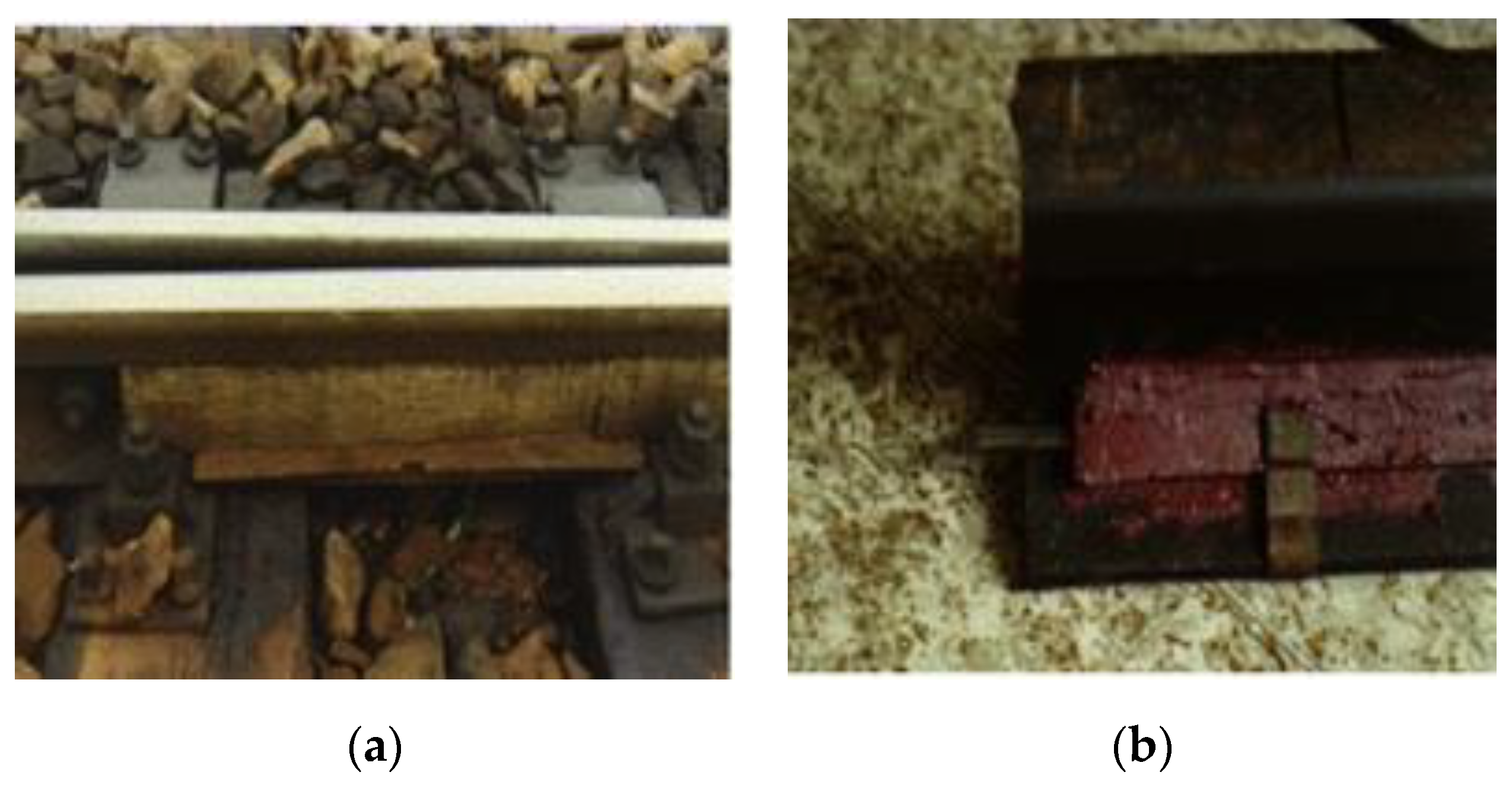
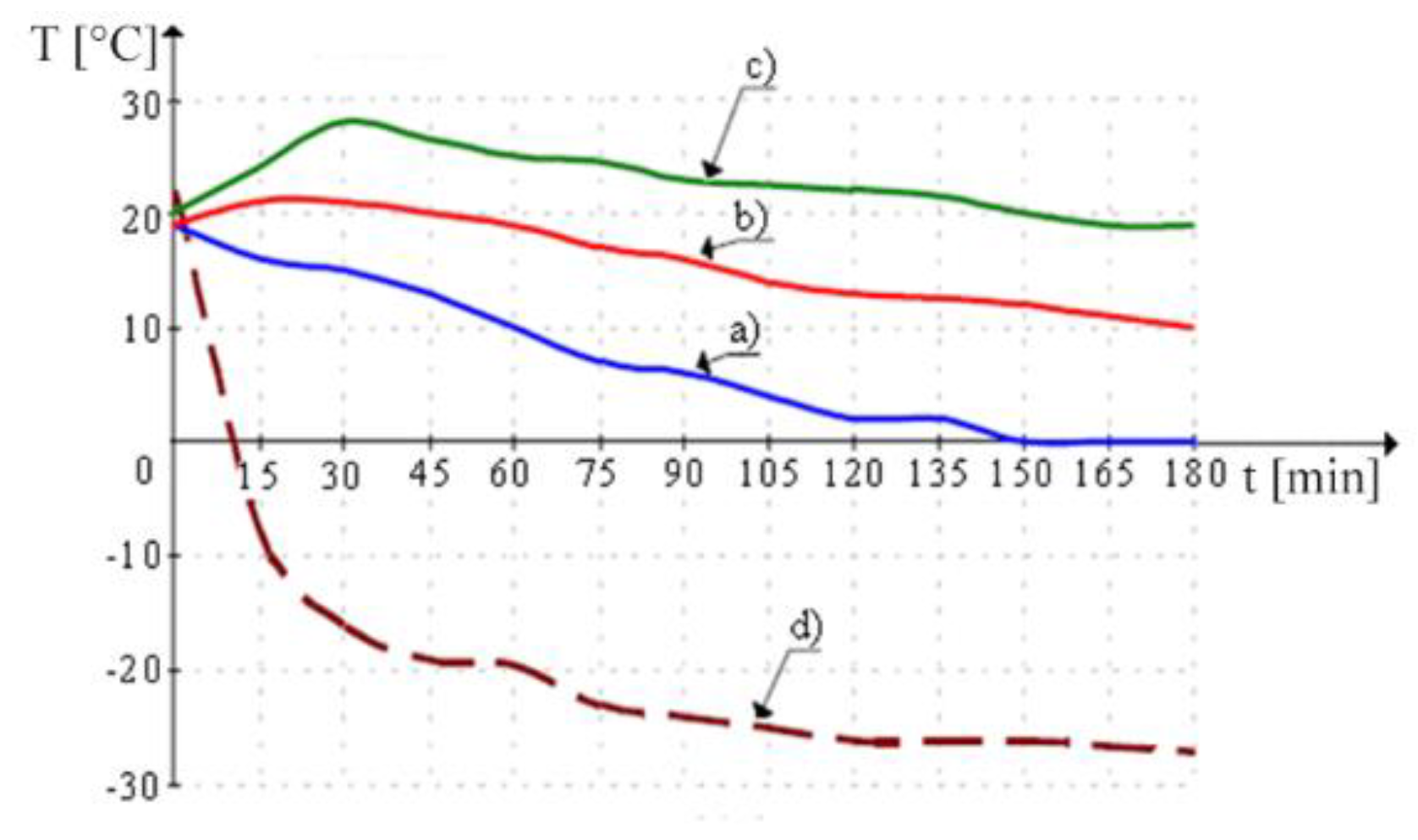
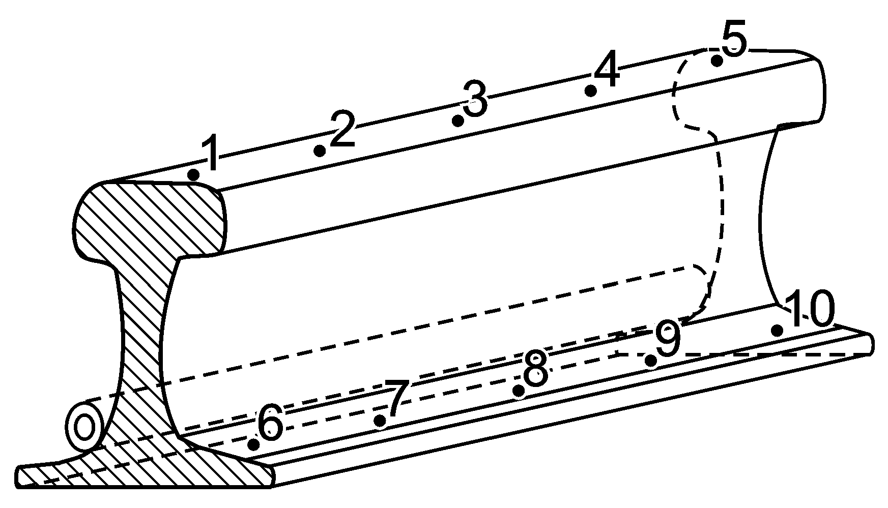
The first attempt at turnout heating with 50 Hz variable magnetic field was conducted in Poland in 1978/1979 on five turnouts of Poronin station and 26 turnouts of Tarnów West station. Heating rods in an insulation coating were utilized (
Figure 6) [
14]. A rod was not in galvanic contact with a stock-rail. The rods were made of copper wrapped in Teflon tape and placed inside a steel guard. A rod was supplied with 3–3.3 V and 50 Hz, while currents across a rod reached 350 A. The operating principle of the method consisted in heating a stock-rail with eddy currents induced therein (
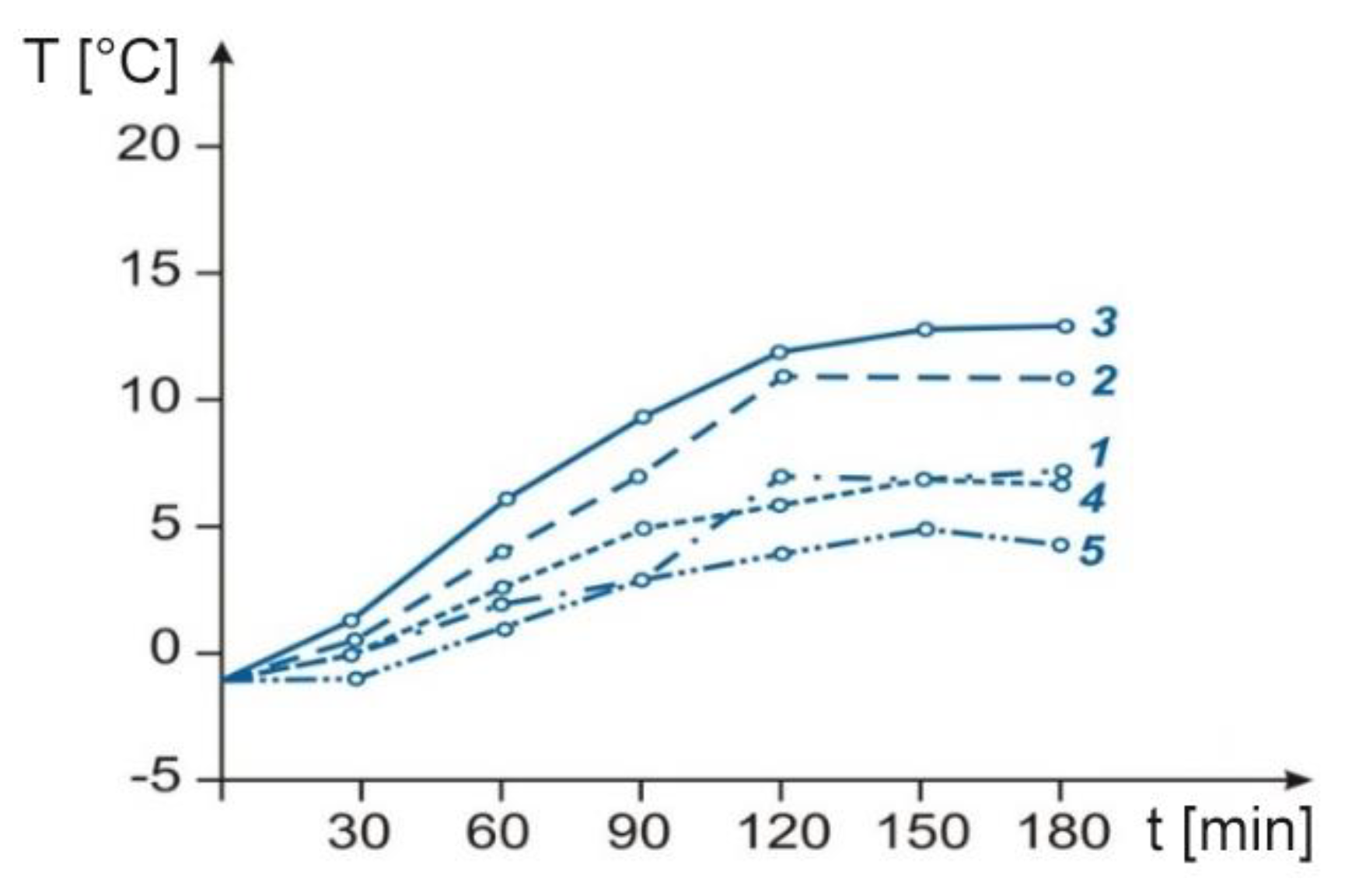
Figure 6). Variations of stock-rail head and web temperatures are shown in
Figure 7 and
Figure 8. Location of a measurement point affected final temperature values. Induction heating proved to have the following advantages over resistance heating: lower electricity consumption, lower operation/maintenance costs, more effective removal of snow/ice as a rail heats more quickly, low safe voltage, lower temperatures of the heater (about 65 °C), longer life of an induction heater, and slower drying of greases.
In spite of its lower energy consumption compared with RH, this method of induction heating was not applied in practice to turnouts. The standard of technology failed to guarantee reliable operation of the system and the solution was abandoned as a result.
Development of power electronic equipment has contributed to improved energy efficiency of electricity conversion and miniaturization of inductors used in the process of induction heating. In the age of new technologies, the concept of turnout induction heating has resurfaced. A device made by winding (1) around a substrate plate (2) and causing the latter to induction heat is one such solution (
Figure 9) [
15]. The area heated expands by winding around the substrate plate. Thermal conduction from the substrate plate to the stock-rail and switch-rail prevents ice formation. Coil does not protrude substantially out of the sleeper and thus does not interfere with maintenance or require dismounting. The solution is effective at snow and ice melting, however its extensive mechanical design makes it impracticable.
The system of induction turnout heating depicted in
Figure 10 contains an inductor (1) that can be sunk, inbuilt, or incorporated into a sleeper or another turnout element [
16]. Protruding parts of the heating system, subject to mechanical damage, are eliminated. The system can operate at high frequencies of the supply voltage (2). An inductor breakdown requires replacement of a rail fragment (3) and more faults may arise when movable switch-rails are heated.
Figure 10 shows a solution where the inductor is placed in a duct cut in the rail foot.
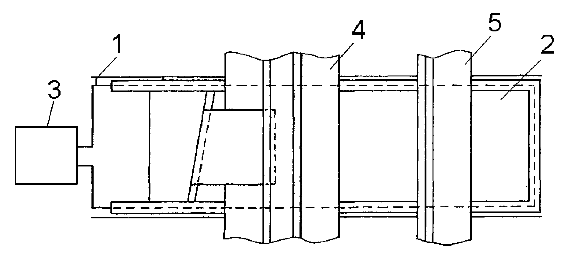
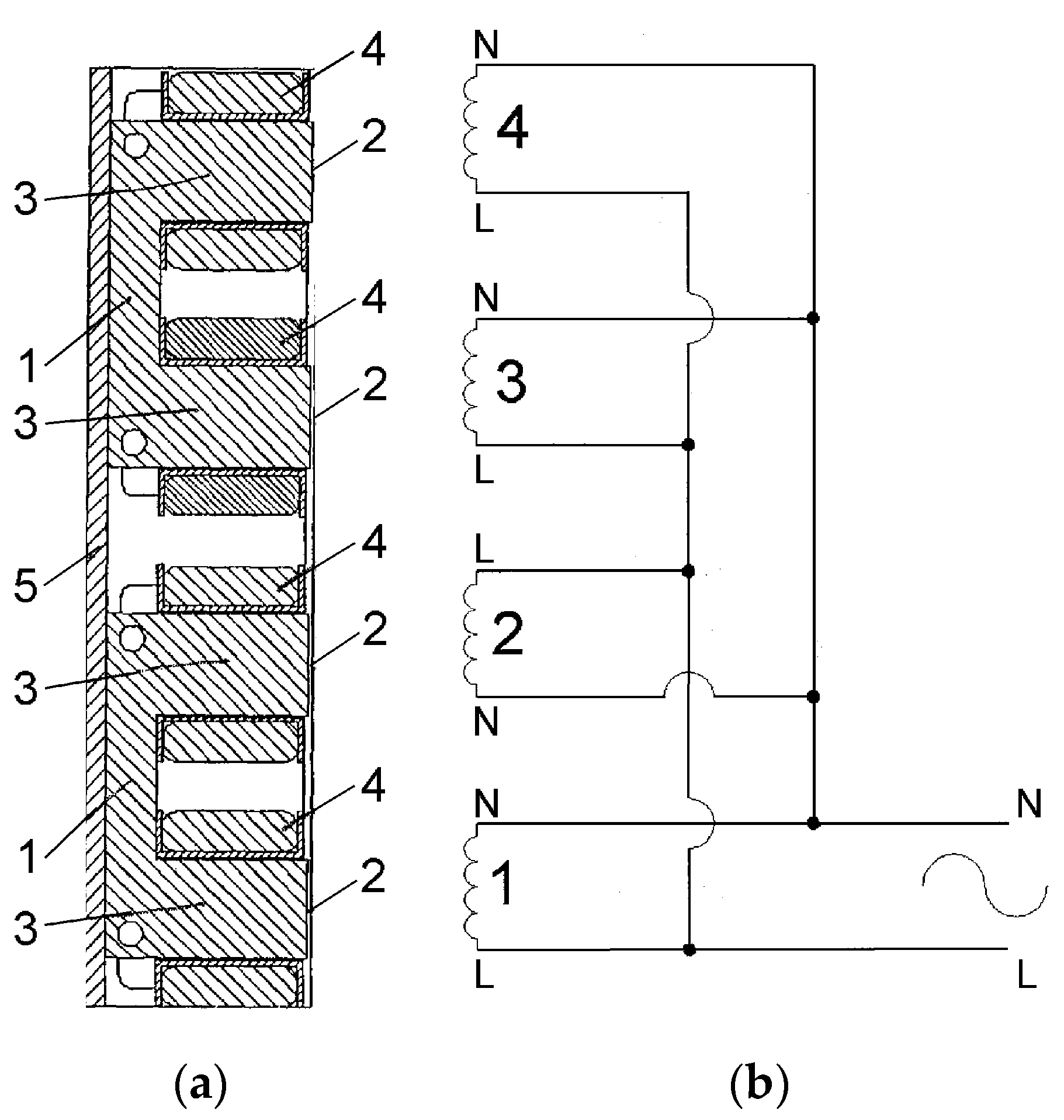
Figure 11 shows a rail heating module consisting of two magnetic field inductors (1), each with two poles (2) oriented towards a rail to be induction heated. Each inductor consists of a magnetic core (3) and windings (4). The poles adhere to the rail web surface. Characteristically, a magnetic flux across one pole has a sense opposite to those of fluxes across the remaining poles. This effect is achieved by modifying polarity of voltage supplied to winding 2 (
Figure 11b) [
17,
18]. The modified polarity improves efficiency of rail heating. The magnetic field of the single pole attracts one of the magnetic fields from one of the other three poles and, as a result, two remaining magnetic fields with the same polarity are obtained. These two magnetic fields counteract one another and the magnetic fields are spread across the rail as a result. By this placement of the coils, uniform heating is achieved.
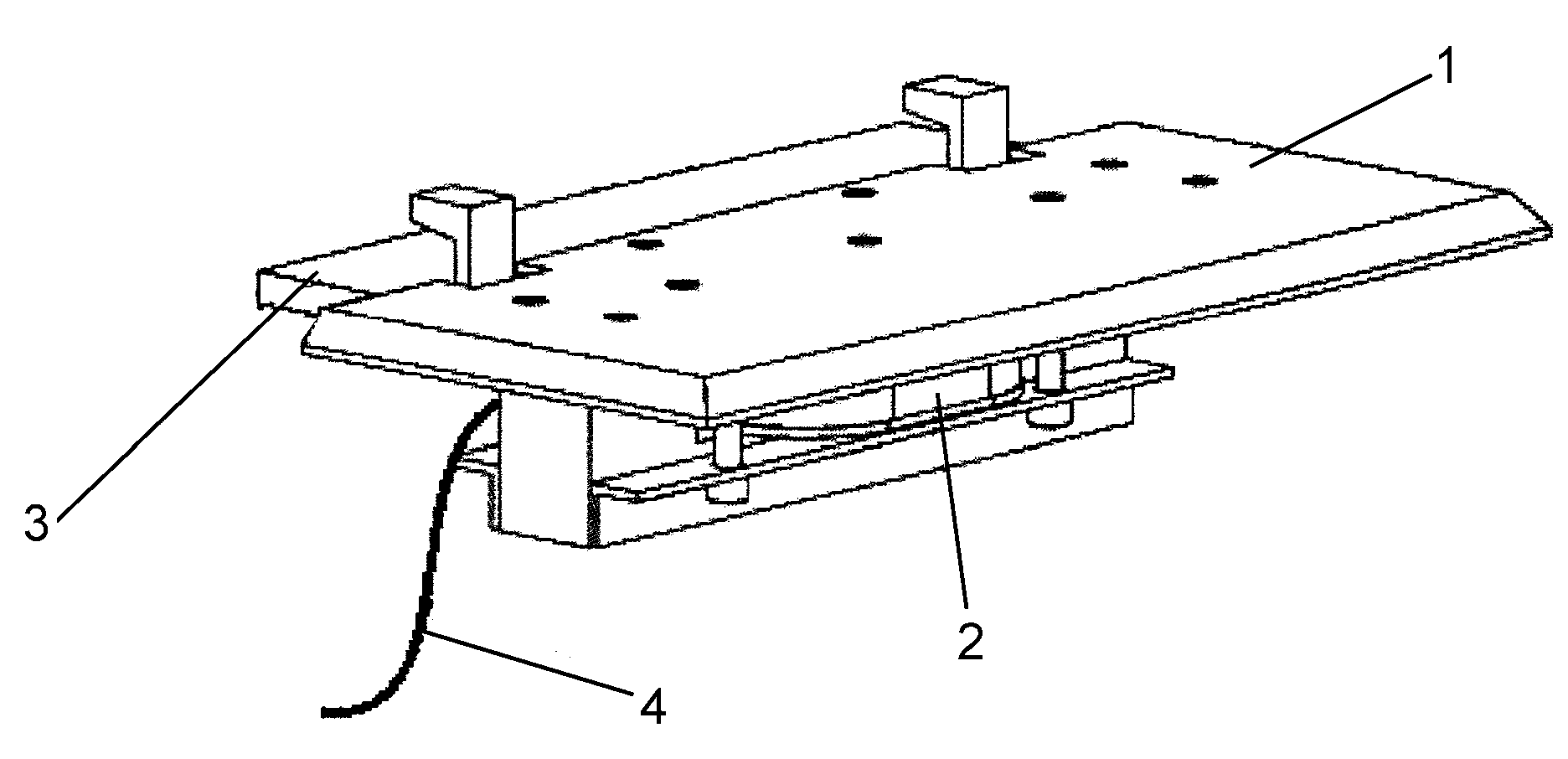
Simple design of the induction heater (1), plates of high thermal conductivity, and threaded fixture to the stock-rail web (2) are characteristics of the device shown in
Figure 12 [
10]. An extensive heating surface, low sensitivity to mechanical damage, and easy access to the apparatus when servicing are advantages of this solution. Unfortunately, it is not clear how the inductor winding is to be mounted. Simplicity of the solution, the possibility of installing the heater between the switch-rail and stock-rail, easy installation without interfering with other electric systems of a rail line, and effective and fast heating of the stock-rail head make this solution particularly interesting.
Another device for melting snow on turnouts by induction heating of the rail web is presented in
Figure 13. It consists of a heater (2) and a clamping system (3). The electromagnetic heater (2) adheres to the rail web (1). An inductor producing a variable magnetic field (5) and a ferrite protective plate (6) are the basic parts of the heater. Placement of a power supply and control system (4) within the heater (2) is characteristic of this solution. Its simple design, high efficiency, fast snow melting, and applicability to all turnout models are among its advantages [
20].
Figure 14 presents a modern solution of turnout induction heating [
21,
22]. This setup consists of an internal coil that generates a magnetic flux in the main core. The heating plate is made of a material that has poor magnetic properties, causing losses in the magnetic flux. The heat from the heating plate is distributed to the space between the stock-rail and switch-rail. The heating element reaches its operating temperature of about 120–135 °C within five minutes, melting away snow and ice very effectively. Because of this rapid warming, it is enough to turn on the heater only when snowfall has begun. It provides for high energy efficiency saving about 60% costs compared to systems based on resistance heating. This heating method effectively melts snow between the stock-rail and switch-rail. It is not known how efficiently ice is melted from the stock-rail head when the switch-rail is moved away.
The turnout induction heating equipment illustrated in
Figure 9,
Figure 10,
Figure 11,
Figure 12,
Figure 13 and
Figure 14 are notable for the variety of novel technological solutions. The authors are not aware of any laboratory test results or practical implementations of these solutions. Absence of such publications is evidence of the scale of the problem of effective turnout de-snowing and the consequent safety of rail traffic. Any results for effects of these systems on rail control systems are not available either.
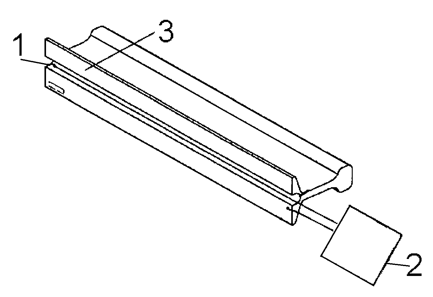
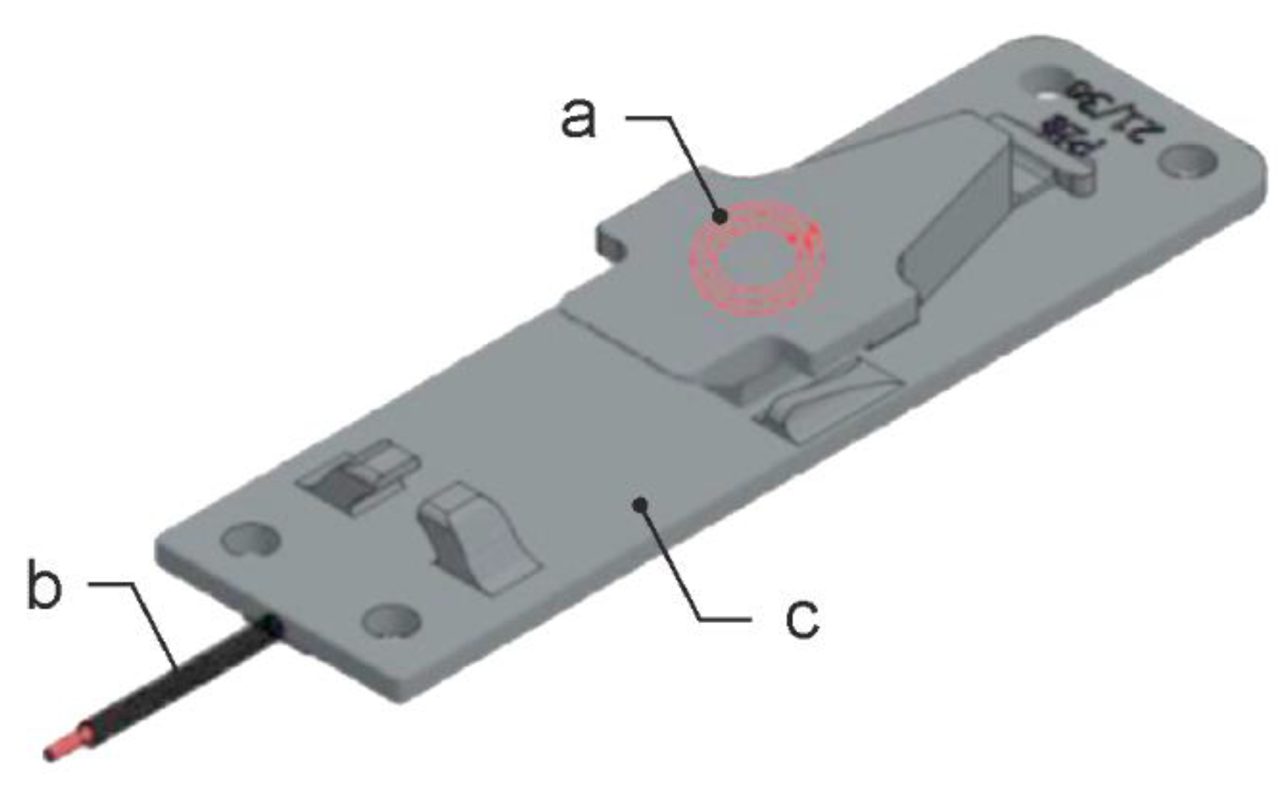
An original turnout induction heating solution is depicted in
Figure 15 [
23,
24]. Inductor a is installed in the part of the slide plate c along which the switch-rail travels. The inductor winding is supplied from a high-frequency voltage generator c. The solution is simple in its design. Heat released in the process of induction heating increases the slide plate temperature, while temperatures of the stock-rail and switch-rail, which are in direct contact with the slide plate, rise as well. Such a heating system appears energy efficient, since ice or snow should melt rapidly in the space between the stock-rail and switch-rail and on their heads.
Owing to the original method of inductor attachment and expected high energy efficiency, this article evaluated heating properties of the device compared to those of universally used resistance heating.
4. Data and Methodology of Experimental Turnout Heating
Keeping a switch-rail and stock-rail snow-free for the purpose of safe turnout operation is the key objective of the turnout heating process. Complex design of a turnout, changing position of switch-rail relative to stock-rail, variable weather conditions, and a heating method in place have decisive impact on effectiveness of heating. Energy efficiency of turnout heating should be understood as the process of transforming electricity supplied to a heating device into an effective quantity of thermal energy capable of removing snow and ice from all crucial parts of a turnout over an adequately short period of time. At the same time, energy used to this end should be as low as possible. Safety of rail traffic is the overarching criterion in evaluation of energy efficiency of heating equipment.
Experimental testing of energy efficiency of turnout heating is a long process. The turnout’s complex design makes precise analysis of its heating difficult. In real conditions, changeable weather and snow brought by passing trains are some added factors interfering with the analysis. A comparative analysis of energy efficiency of RH and IH systems based on climatic chamber testing is undertaken in this paper.
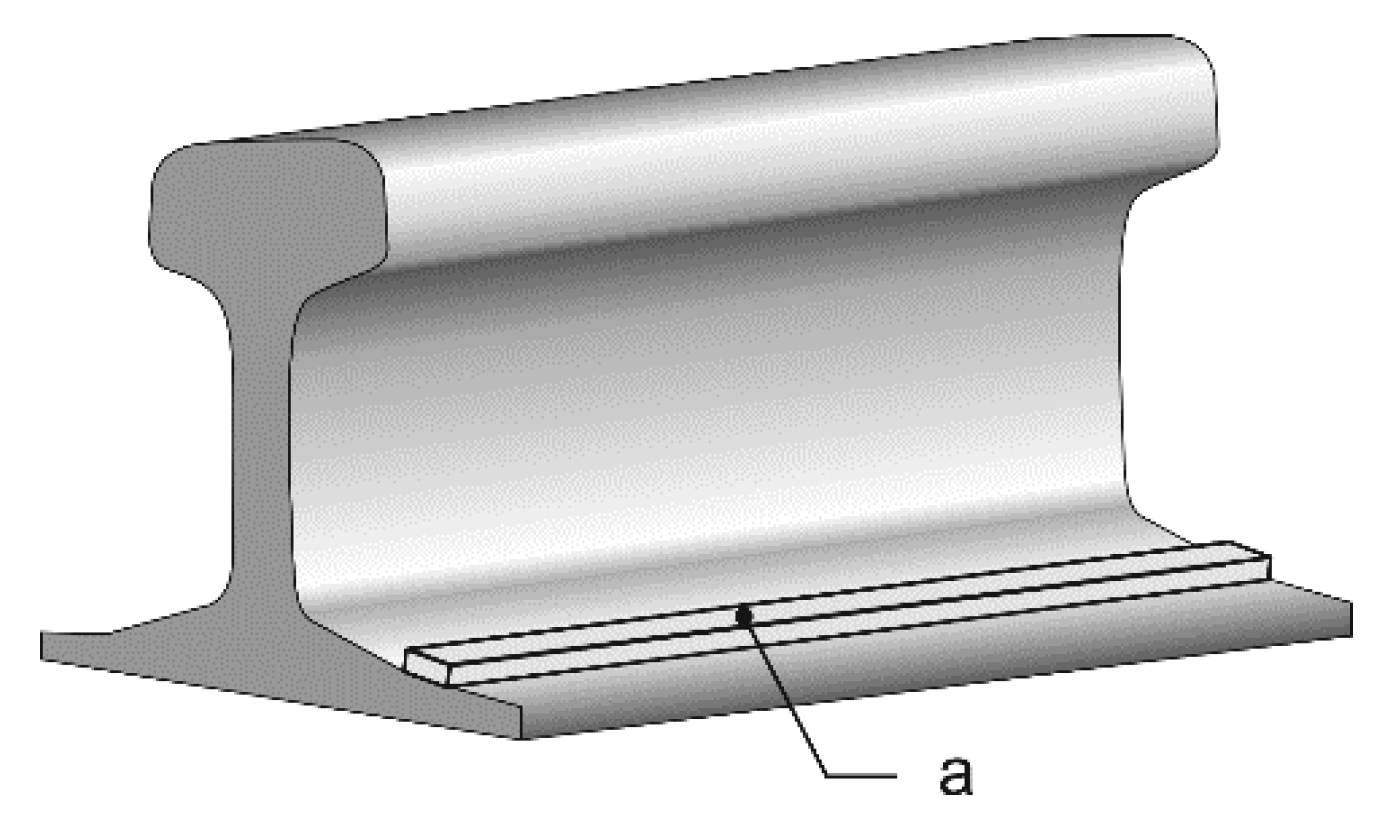
The comparative analysis of IH (
Figure 15) and RH (
Figure 1) addresses the following conditions, known from the literature and the authors’ own experience [
1,
3,
4,
12,
14]:
Turnout heating should aim for high energy efficiency, associated with total snow or ice melting in the area between a switch-rail and stock-rail while consuming a minimum of electricity.
RH exhibits low efficiency of snow or ice melting on the slide plate from the switch’s internal side. This is caused by the fact that only thermal conductivity of the material is taken advantage of. In practice, this may mean insufficient heating of a lubricant on the slide plate plane along which the switch-rail travels. The lubricant maintains good tribological properties at temperatures above −30 °C [
25]. However, as the switch-rail travels along an iced slide plate, the lubricant may wear (vanish) faster from the slide plate surface and friction between the switch-rail and slide plate surfaces may increase. Not heating the lubricant but melting ice from the slide plate surface before the switch-rail moves should be the goal.
IH uniformly heats the entire surface of the slide plate; therefore, lubricant properties remain identical all along the path of the switch-rail’s travel.
IH rapidly melts snow or ice all along the slide plate on the switch-rail’s internal and external sides. This improves snow melting above the slide plate surface by thermal radiation in a space delimited by the stock-rail and switch-rail dimensions.
There is a risk IH will insufficiently melt snow deposits between the slide plates in the space between the stock-rail and switch-rail. This may be particularly dangerous as the switch-rail shifts towards the stock-rail, causing insufficient contact between both the parts.
As the switch-rail touches the stock-rail in RH, energy efficiency improves considerably since thermal energy losses to the air diminish. Snow and ice in the heated space melt more quickly.
As the switch-rail touches the stock-rail in RH, temperature of the heating element reaches 200 °C. The rear part of the slide plate between the stock-rail and switch-rail heats rapidly and the lubricant on the slide plate surface dries ([
25] gives the lubricant’s flash point of 110 °C). The risk of escalating friction between moving parts of the turnout and their freezing to one another emerges.
The stock-rail can be positioned in relation to a sleeper by means of a plastic washer. This significantly impairs thermal conductivity conditions from the stock-rail to the for both the heating systems.
In general, an in-depth assessment of advantages and disadvantages of both the systems of turnout heating should be attempted, considering experimental results and guided by the overarching criterion of safe rail travel.
In view of the above, the authors have proposed the following assumptions for efficiency assessment of turnout heating:
Figure 7 and
Figure 8 imply rail temperature may vary considerably when heated. Depending on sensor location, temperature on the rail head ranges between (5–12) °C after 180 min of heating, while the web reaches (5–17) °C. When tested in a climatic chamber, temperature distribution along the rail head or web may vary considerably from temperatures measured at specific locations. Therefore, reading errors of sensors themselves are ignored in analysis of rail heating results and treated as an acceptable part of measurement inaccuracy.
Analysis of both the systems’ heating efficiency may be liable to error as snow is absent from a turnout in climatic chamber testing. Its melting is the key function of heating systems. To substitute for snowfall, the turnout was iced prior to heating by spraying the switch-rail and stock-rail with water, then the instant of total ice melting was observed.
It should be noted that there is no unambiguous method for comparing both the systems of turnout heating. Taking the above conditions and assumptions into account, the authors have formulated the following criteria of assessing efficiency of turnout heating:
For an open turnout, the part of the slide plate between the switch-rail and stock-rail must be free from snow and ice; in addition, snow cannot prevent continuing contact of the switch-rail and stock-rail after the switch-rail changes its position.
For a closed turnout—the switch-rail touching the stock-rail—the part of the slide plate between the switch-rail and the medium section of the turnout must be free from snow and ice. The contact between heads of the switch-rail and of the stock-rail cannot be iced, either.
Moving parts of the turnout are completely free from snow or ice in a relatively short period of time.
Quantity of electricity required to heat a unit distance of rail should be as low as possible.
Dynamics of temperature should be maximum possible.
Realizing the foregone conditions is chiefly based on reading temperature variations at designated points of the turnout and visual verification of the moment ice turns into water on selected turnout elements from the time the heating begins. Given temperature values, dynamics of its variations, location of the measurement sensor, and time of the heating, the process of snow melting can be analyzed.
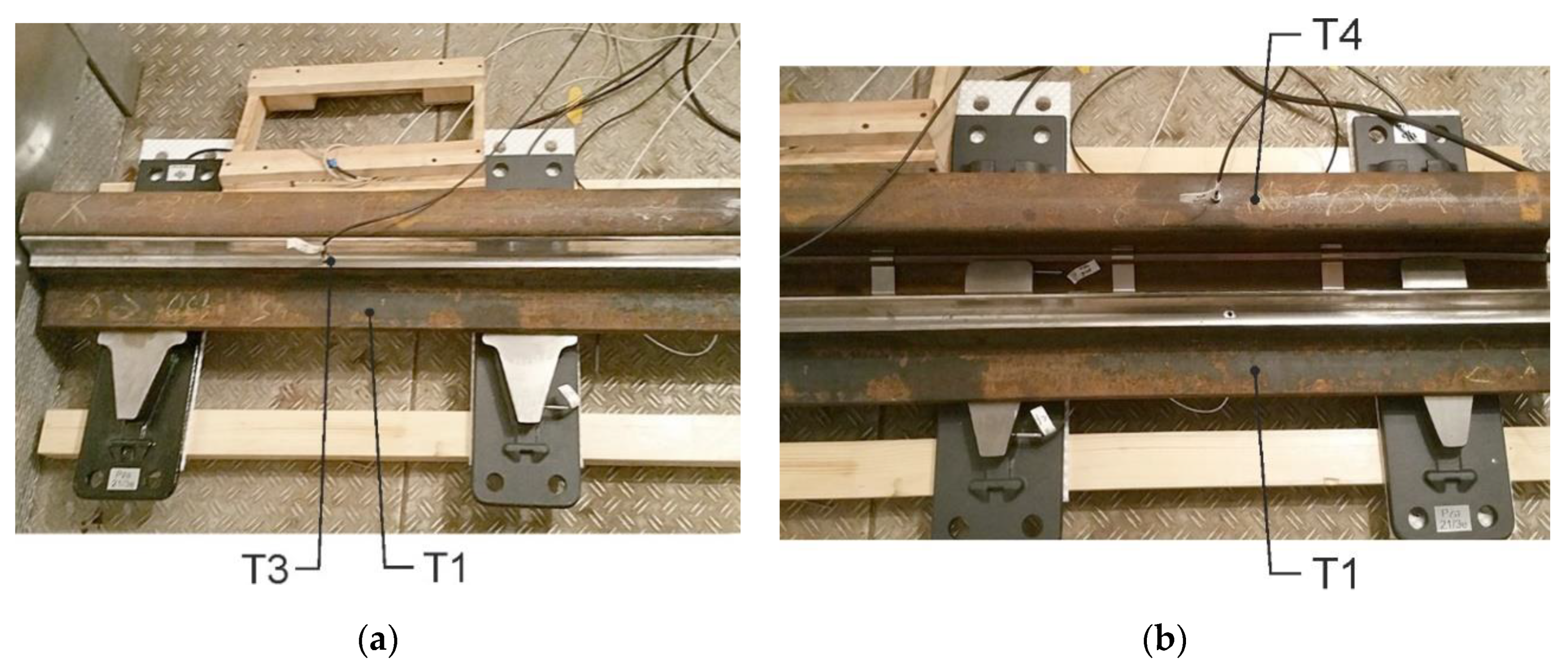
6. Results and Discussion of Test Results for Resistance and Induction Turnout Heating
Measurement results for the ambient temperature of −30 °C are illustrated in
Figure 18. Two positions of the switch-rail in relation to the stock-rail were assumed: in contact and 7 cm away. For the switch-rail touching the stock-rail in resistance heating, maximum temperature (T1) increment was 15 °C for the switch-rail foot and stock-rail head (
Figure 18a). When the switch-rail was shifted away from the switch-rail in resistance heating, temperature of the stock-rail head (T4) was approximately −13 °C while the temperature (T1) of the switch-rail foot reduced dramatically (
Figure 18c). Temperature of the stock-rail foot (T2) was identical in both cases and its increment was circa 12 °C (
Figure 18a,b).
In the case of induction heating, the temperature (T5) rose by 25 °C for the slide plate to the side of the stock-rail and (T6) by approximately 15 °C for the part of the slide plate towards the switch-rail for both switch-rail positions (
Figure 18b,d).
The switch-rail’s position has no marked effect on reaching maximum temperatures that are lower 0 °C for both the heating systems. Negative temperatures at each turnout point were noted for both the heating systems. This means they do not operate efficiently at such low temperatures.
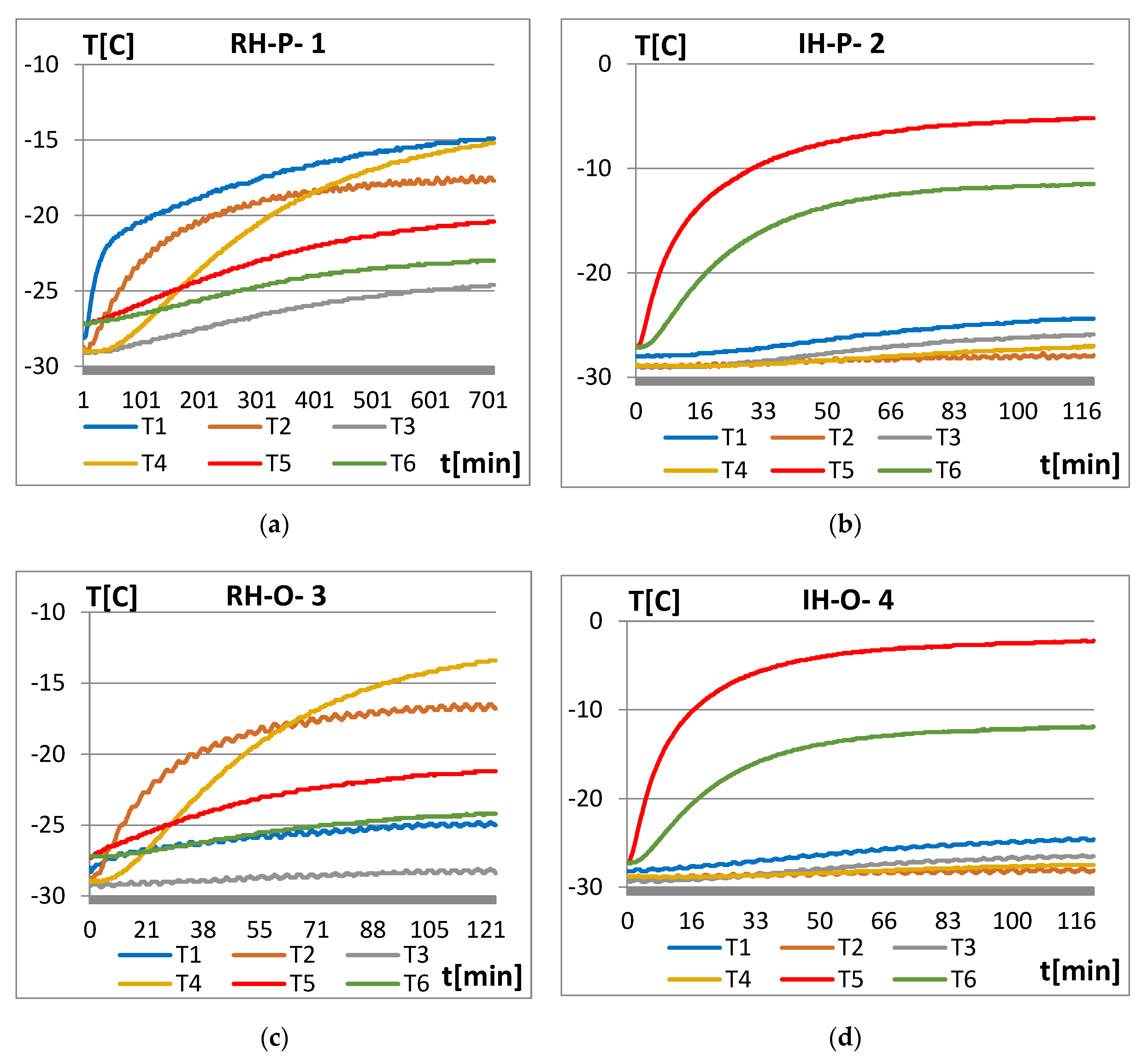
Since the heating is inefficient at −30 °C, the testing was undertaken for −5 °C, the most frequent annual average in temperate climate (
Figure 19). Maximum temperatures of selected turnout parts are well in excess of 0 °C, contributing to melting of snow. For resistance heating and the switch-rail in contact with the stock-rail, maximum temperature increment was circa 14–15 °C for the head (T4) and foot of the stock-rail (T2), as well as for the switch-rail foot (T1) (
Figure 19a). When the switch-rail was moved away from the stock-rail in resistance heating, temperature (T4) of the stock-rail head rose by ca. 15 °C while temperature (T1) of the switch-rail foot fell dramatically to approximately 0 °C (
Figure 19.). Temperature (T2) of the stock-rail foot was identical in both cases and increased by 12 °C (
Figure 19a,c).
As far as induction heating is concerned, temperature (T5) grew by 22 °C for the slide plate from the side of the stock-rail and (T6) approximately 16 °C for the slide plate towards the switch-rail (
Figure 19b). In the case of induction heating, shifting the switch-rail away caused temperature (T5) of the slide plate from the side of the stock-rail to rise by ca. 25 °C (
Figure 19d). Temperatures (T2, T4) of the entire stock-rail are below zero. This was a result of the poor heat conduction between the slide plate and the switch-rail.
It can be said the switch-rail’s position and changes of air temperature had no significant impact on increments of turnout temperatures in the foregoing cases. During heat induction, slight rises of stock-rail and switch-rail temperatures were observed, as the turnout parts did not have major roles in the process of snow melting. This indicated thermal energy of induction heating was generated in the slide plate and was for the most part convected in the area of a stock-rail and switch-rail. This was evidence of good snow melting conditions and high heating efficiency. Higher stock-rail temperatures were produced during resistance heating. This caused additional dispersion of thermal energy into the air without influencing snow melting between the stock-rail and switch-rail. Heating efficiency was lower for the same electric power, i.e., 450 W for both the heating systems tested.
Snow melting across the slide plate surface was attempted in order to ensure properly lubricate the slide plate and switch-rail surface. For induction heating, the slide plate temperature was considerably greater than the melting point, whereas the temperature increment was ca. 5 °C in the case of resistance heating when the switch-rail moved away. This value determined the minimum ambient temperature at which the switch-rail may traveled along an ice-free slide plate surface.
There was more effective snow melting in the stock-rail and switch-rail space, as well as more reliable lubrication of moving turnout parts expected in the case of induction heating. In the practice of resistance heating, lubricant was additionally dried in the vicinity of a heating element due to the latter’s high temperatures of approximately 200 °C. Tribological parameters of a turnout’s moving parts were impaired.
The turnout with a switch-rail shifted toward and away the stock-rail sprayed with water at an ambient temperature of −5 °C. This was done to compare efficiency of both the heating systems. When the switch-rail was away from the stock-rail, the turnout began to be heated after the water had frozen. Ice on the slide plate prevented the switch-rail from moving. During 150 min of resistance heating, an attempt was undertaken to shift the switch-rail, but to no effect. It remained so solidly frozen to the slide plate foot that the upward force could have lifted the entire turnout.
Induction heating was applied in the above conditions of a water sprayed turnout. Water drops began appearing on the slide plate feet after five minutes and it was possible to move the switch-rail. This means resistance forces to turnout drive reduce quickly and quality of lubrication of the turnout’s moving parts is improved compared to resistance heating.
Similar testing was conducted for the switch-rail touching the stock-rail. It was only after 90 min of resistance heating that the switch-rail could be shifted away from the stock-rail due to some ice on the slide plate inside the turnout. On the other hand, the slide plate, stock-rail head, and switch-rail head remained iced together after 30 min of induction heating. The switch-rail could be shifted away, nonetheless. This may suggest greater start-up force in the initial phase of moving the switch-rail away from the stock-rail.
In general, the switch-rail was more ready to shift and lubrication conditions of moving turnout parts were better for the induction heating of an iced turnout with the switch-rail moved away from and moved to the stock-rail than for resistance heating.
Dynamics of temperature variations of selected turnout elements are an important criterion when evaluating turnout heating. This parameter is closely correlated with a system of turnout heating control. Greater dynamics also influence effectiveness of heating, expressed as a high capacity for heat emissions to melt snow.
Based on the temperature distribution across the stock-rail web by means of turnout automatic controls, it was assumed that the heating element temperature in constant operation should vary within (+2–+6) °C (
Figure 20). In Polish weather conditions, the minimum ambient temperature of −10 °C can be assumed at which a heating system is capable of maintaining a turnout snow-free. Snow is rare at lower temperatures. For the minimum ambient temperature
Tam = −10 °C and assuming a maximum temperature of a heated turnout part equal to +6 °C, a maximum temperature increment Δ
Tmax = 16 °C required for the purpose of comparative analysis was adopted.
Given these assumptions, the dynamics of temperature increment are defined as:
where:
—temperature increment over the initial value of
Tam,
Dynamics of temperature increment for the stock-rail web of a turnout installed in the field was 5/20 [C/min] = 0.25 [C/min] (
Figure 20). In turnout testing in a climatic chamber (
Figure 18a), the foot temperature increment for the RH system was 7/23 [C/min] = 0.3 [C/min]. Both the results were comparable, which validated the correctness of adopting the testing methodology with a climatic chamber.
Analysis of temperature increment across one of temperature measurement points for both the RH and IH systems was undertaken to evaluate energy efficiency of turnout heating. Temperature increment ∆
T of this point had a considerable impact on effectiveness of snow melting across moving parts of the turnout and in the space between the stock-rail and the switch-rail. Temperature increment ∆
T defined the difference between a current
T and initial temperature
Tam= −5 °C (
Figure 21) and
Tam = −15 °C (
Figure 22).
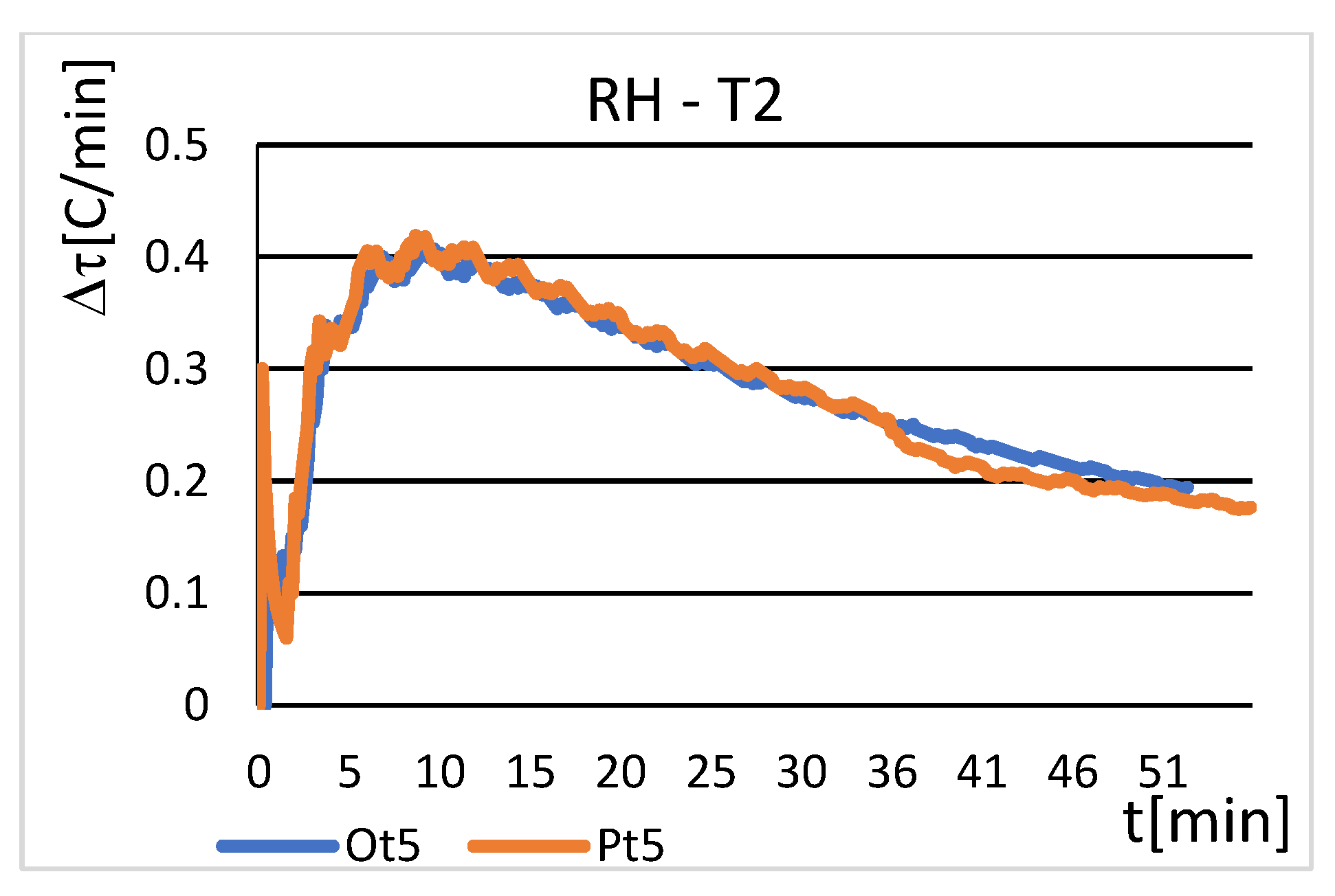
Temperature variations (T2) of the stock-rail foot for the switch-rail shifted away from (Ot) and touched (Pt) the stock-rail. Thus, they were selected for resistance heating RH (
Figure 21). The temperature distribution (T2) was limited to the time interval of 50 min, when effective heating of the stock-rail foot took place. The temperature rose by about 10 °C. The ambient temperature at the time of testing was
Tam = −5 °C. For
Tam < −15 °C. The RH system was inefficient, attaining maximum temperatures below zero.
Dynamics of temperature increment in the adopted time interval were maximum—i.e., approximately 0.4—for an interval of around 10 min (
Figure 23). Temperature increment (T2) and its dynamics were independent from the position of the switch-rail in relation to the stock-rail.
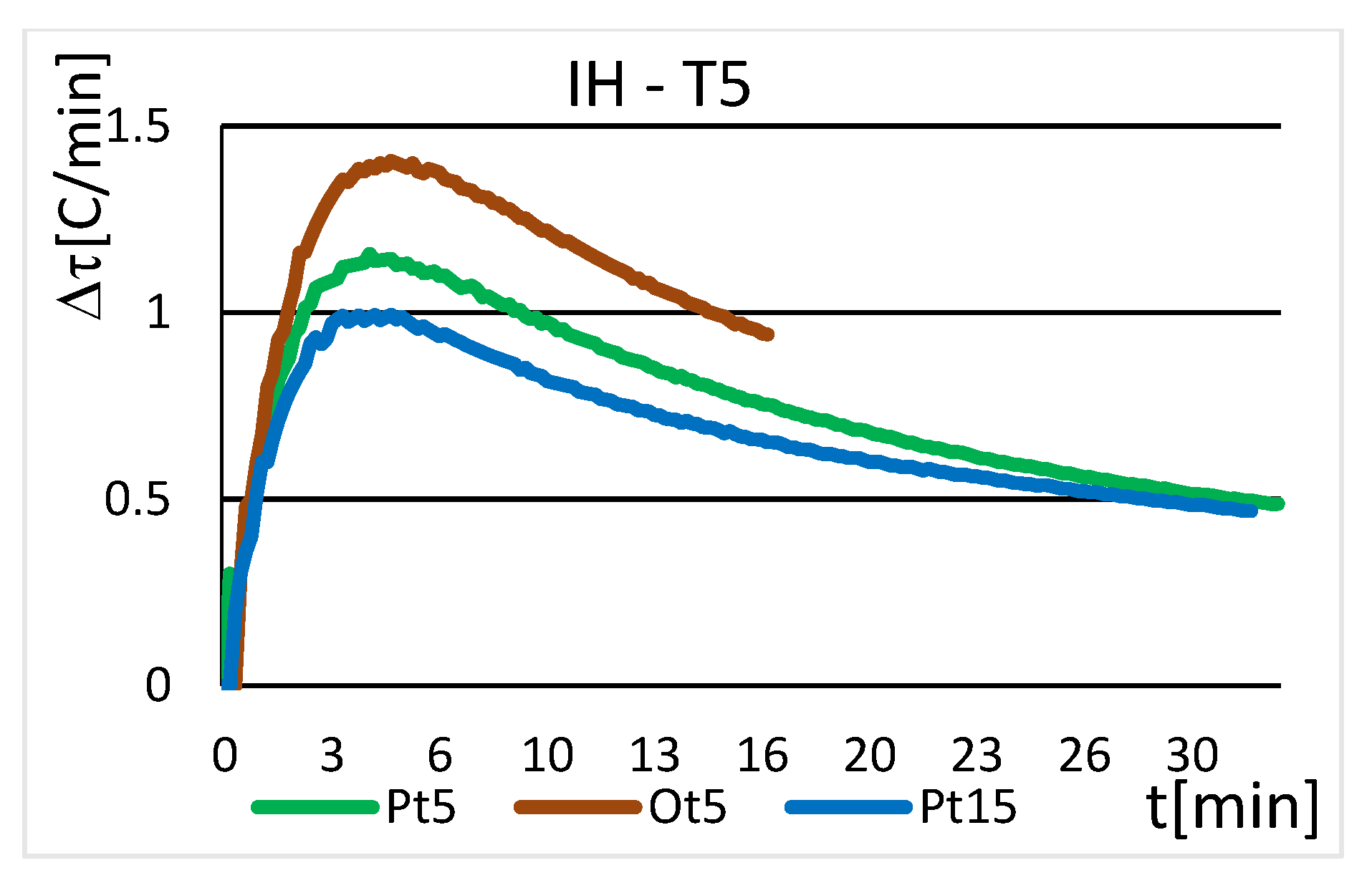
Temperature increments (T5) of the slide plate towards the stock-rail for the switch-rail shifted away from (Ot) and touching (Pt) the stock-rail were selected for the induction heating IH (
Figure 22). The testing was conducted for the ambient temperatures
Tam = −5 °C and
Tam = −15 °C. The IH system was assumed to be inefficient for lower ambient temperatures.
The temperature distribution (T5) was limited to the time interval of 35 min. The temperature increments gained their maximum required value then: ∆
Tmax = 16 °C (
Figure 22). The time interval needed to reach ∆
Tmax depended on the switch-rail’s position (Ot or Pt) and ambient temperature
Tam. When the switch-rail was in contact with the stock-rail, the heating time approximately doubled. This was not a major limitation since snow melting in the space between the switch-rail and the stock-rail was not required in the circumstances. The 10 °C lower ambient temperature contributed to extension of the heating time by several minutes.
Dynamics of temperature increment in the IH were maximum in the range Δ
τ∈(1–1.4) for approximately 5 min (
Figure 24). Shifting the switch-rail away from the stock-rail or increasing the ambient temperature contribute to greater dynamics of the temperature increment.
In general, the maximum dynamics of temperature increment in induction heating were approximately 3–4 times higher than in resistance heating, thus becoming maximum twice as soon. As a result, the slide plate was faster to reach its temperature set by the IH control system than in the RH, thereby melting snow more efficiently.
Results of the climatic chamber testing also required analysis with regard to their uncertainty. The uncertainty of the measurements were related to a higher number of possible sources of impact, i.e., imperfect realization of a measured quantity, incomplete knowledge of impact of external conditions on the measurement procedure, finite resolution capabilities of measurement equipment, simplifying approximations, and assumptions adopted for the testing.
Figure 6 and
Figure 7 indicate that temperatures across the stock-rail head (T4) varied at the same instant when the rail was heated. Temperature variations between points 5 and 3 may reach ca. 10 °C. For the purpose of climatic chamber testing, the sensor (T4) was placed 0.5 m from one rail’s end and 1 m from the other end. Rail head temperatures in the remaining positions are unknown. A rail was considerably longer in real turnouts, which may have added effect on temperature.
The imperfect temperature measurements made the results display slight oscillations (
Figure 18 and
Figure 19). This could be explained with variable conditions in the climatic chamber. The temperature varied a little.
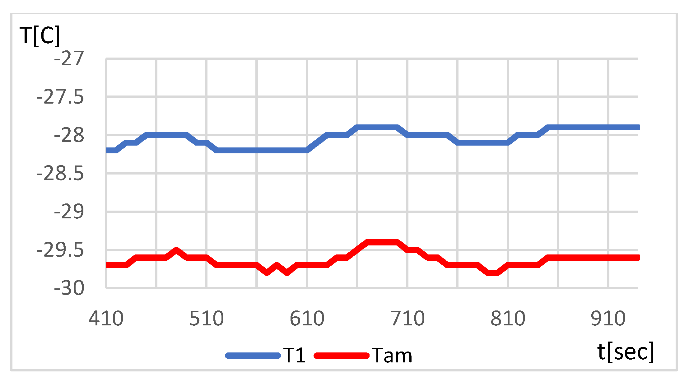
Figure 25 shows a correlation between temperature in the climatic chamber (
Tam) and temperature of the switch-rail foot (T1) in the time interval of 500 s. As
Tam grows, temperature (T1) increased, and vice versa. Low-amplitude oscillations appeared in a broader time interval.
Temperature changes on the switch-rail foot (T1) exhibited a sudden drop at 33 min (
Figure 19a). This was most likely caused by shifting of measurement wires and loss of precise contact.
Oscillations of a significant amplitude were observed in the initial phase of the measurements. According to Equation (3), dynamics of temperature variations defined how quickly temperature increased from the start of the heating process. As the measurement accuracy of 0.1 °C was adopted, the temperature change ∆
T (3) was constant, 0.1 °C, in the time interval of 110 s. As the time of heating increased, temperature dynamic variations diminished. Therefore, temperature variability in the climatic chamber had some impact on the process of oscillations (
Figure 25).


