1. Introduction
The microgrid (MG) is the development trend of the modern electric power system, since the renewable energy power generation is one of the available means to solve the global energy crisis and decrease environmental pollution [
1,
2,
3]. The conception of microgrid has been defined as a small controlled power system composed of generators, loads, an energy storage system, and control units. The microgird can be operated in two modes: grid-connected and island-connected to serve in the specified area to facilitate the supply of power to user’s premises and improve the quality of power [
4,
5]. According to the form of electricity, the microgrid is mainly divided into AC and DC microgrids [
6]. The DC microgrid can reduce energy conversion, improve system efficiency and reliability, and it is much easier to connect different kinds of energy sources and loads to DC microgrid when compared with the AC power grid [
7,
8].
To ensure the stable operation of DC microgrid, it is necessary to comprehensively consider the operation status of each unit in the microgrid and formulate an effective energy management strategy to meet different system requirements. Conventional centralized control and decentralized control strategies are used for the energy management system. The centralized approach relies heavily on communication; i.e., one single point of failure can influence the entire system [
9]. At the same time, decentralized control has limitations of poor voltage regulation and control accuracy, which affect effectiveness and reliability [
10].
The distributed control is an effective approach to solve the disadvantages of centralized and decentralized control, which requires only neighbor-to-neighbor information on a sparse communication graph [
11,
12]. In each unit, it has its local controllers, which can operate independently according to the local controller. The control objectives, such as current sharing, voltage restoration, and state of charge (SOC) balancing, are easily achieved. Hence, distributed control strategies can enhance system reliability and modularity and provide wider functions than centralized control [
13,
14].
To mitigate the uncertainty problems of renewable energy sources, the microgrid is commonly quipped with energy storage units (ESUs) to supply and store system power [
15]. The difference in battery characteristics hardware parameters and control accuracy of control systems may lead to the imbalance of SOC between parallel energy storage systems [
16]. Hence, in order to balance the output power of each ESU and to coordinate the battery control in different states, an effective load sharing method is needed. Specifically, a higher SOC unit should supply more power; in contrast, a lower one should supply less. In this way, SOC balancing can be achieved [
17] When the DC microgird operates in the island mode, the accurate proportional power sharing can be realized through droop control, which becomes an essential means to achieve system energy management [
5]. However, given the difference between the line impedances, there are still some limitations in using droop control to equalize the current; i.e., droop control can influence the output voltage drop, which may cause damage to the power quality [
18,
19]. To solve this problem, a secondary control method should be applied to realize power sharing between each ESU and to restore the average reference voltage [
20].
The studies on distributed droop control of SOC balancing have been discussed in [
21,
22,
23,
24,
25,
26]. In [
21], a droop method based on SOC was introduced to adjust the droop coefficient and the load sharing speed due to the order of SOCs among ESUs. In [
22], SOC balancing was achieved by adjusting virtual impedance loops by utilizing the coordinated secondary control. A double-quadrant SOC-based droop control was proposed for power sharing in autonomous DC microgrid in [
23]. A distributed multiagent based algorithm was introduced in [
24] to achieve SOC balancing by scheduling the reference voltage. A SOC balancing method based on the distributed secondary level was proposed in [
25] by changing the droop virtual resistances. The authors modified the droop coefficient according to the deviation between local SOC and average SOC value. In [
26], the authors proposed a concept of virtual power rating to calculate the load power sharing algorithm for realizing SOC balancing and power sharing. These studies mainly focused on regulating the reference voltage or correcting virtual impedance, and few considered that the coupling between those two processes may lead to the instability of virtual impedance.
In practical operation, the virtual impedance can be affected by the initialization of the system. It may fluctuate due to the communication noise of the system, even if the loads are constant. The value of virtual impedance not only effects the dynamic performance of the system, but also affects the stability. To overcome this problem, a distributed droop control method is proposed considering the stability of virtual impedance. There are four designed controllers in secondary control level, the aim of which is to balance SOC, achieve accurate power sharing proportionally, restore the virtual impedance, and maintain the local reference voltage of each energy storage unit.
The main contributions of this paper include: (1) By using the control method, the droop coefficient distribution and load distribution is a one-to-one correspondence whose droop coefficient is only affected by the load distribution and topology. Also, system initialization and noise will not have an impact on droop coefficients. (2) The coupling relationship is analyzed by Kron reduction, and the sufficient condition for the uniqueness of droop coefficient is deduced. (3) SOC balancing among each ESU is achieved with accurate proportional power sharing and steady-state analysis is provided.
The paper is structured as follows.
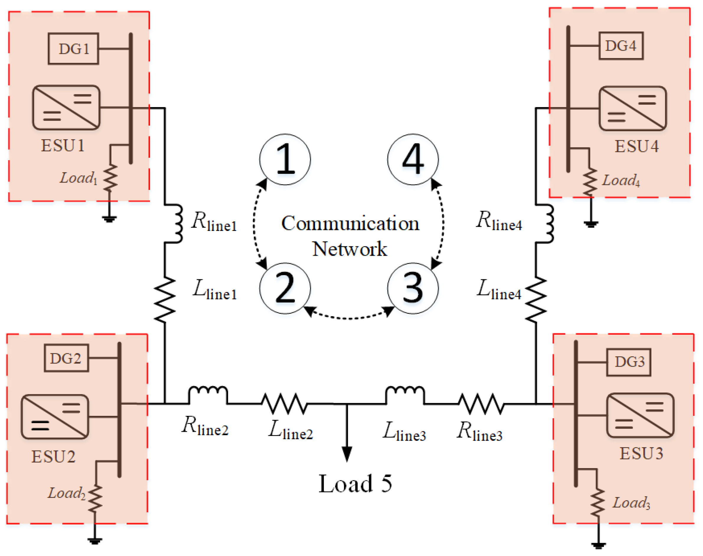
Section 2 demonstrates the problem formulation and system structure. Besides, both output power and voltage only influenced by the system load is proved.
Section 3 illustrates the proposed controller, which consists of a current sharing controller, SOC balancing controller, virtual impedance correction controller, and the local voltage controller, and provides a steady-state analysis. A small-signal model was implemented to ensure the stability of the controller strategy in
Section 4. The simulation results are shown in
Section 5; they validate the effectiveness of the proposed control scheme. At last,
Section 6 concludes.
3. Proposed Secondary Control Scheme
In this section, the control method designed for droop-controlled DC MGs is introduced by using a slope-adjusting method. The control scheme consists of four controllers. The distributed SOC balancing controller guarantees that the SOC of the ESUs are balanced so that the ESU with higher SOC should supply more power, while the unit with lower SOC supplies less. The purpose of the distributed current sharing controller in this paper is to achieve proportional accurate current sharing. However, if only the current and SOC compensation controllers are used, the droop coefficient can have multiple combinations, which means that the droop coefficient can be very different from the initial value. Hence, an additional compensating controller, i.e., the average droop coefficient controller, is designed in the control method. Through the average estimator controller, the uncertain droop coefficients could be avoided. Also, the information of droop coefficients is only exchanged among the interface of converters through the communication network, and is restored to a rated value. Then, the local voltage controller adjusts the reference value of the voltage through the feedback of the output current. Three compensation controllers are employed in the secondary control scheme to improve the dynamic load sharing performance of the system.
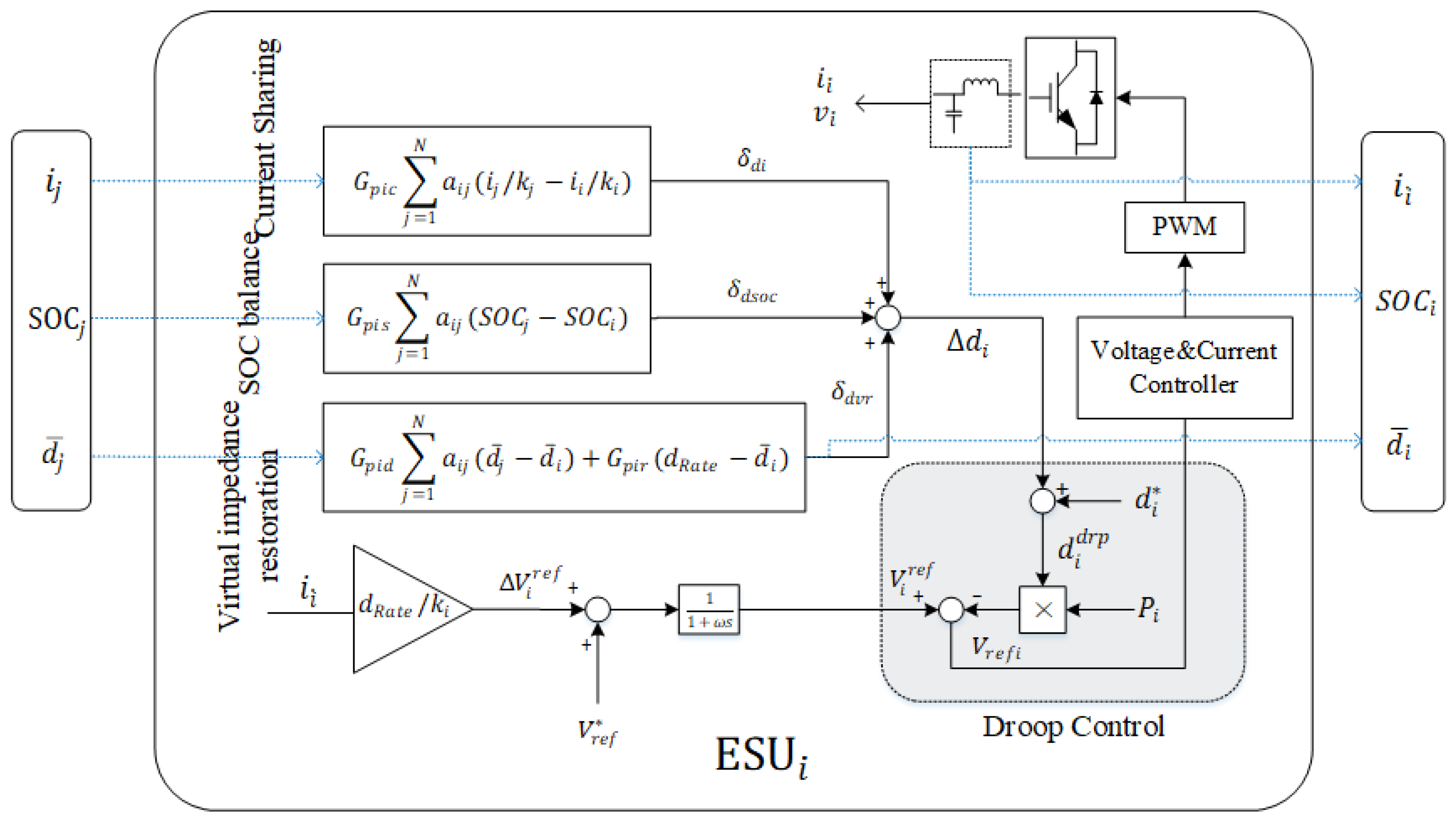
The boost converters are used as DC-DC interfaces to avoid loss of generality and the control strategy is consists of inner loops, a DC droop, and a secondary adjustment. The inner loops contain the current loop and voltage loop to control the output voltage of converters. The voltage produced by the droop controller is the reference value of the inner-loop control. The detailed diagram is shown in
Figure 2.
The improved control method can be rewritten as follows:
where
is the given reference value of the droop coefficient,
is the rated value of the microgrid, and
and
are the correction terms of the reference voltage and droop coefficient, respectively.
The secondary controller produces three correction terms to modify the droop coefficient. The adjustment of each droop coefficient in the proposed strategy can be expressed as follows:
where
,
, and
are the current correction term, SOC correction term, and the droop coefficient correction term, respectively.
3.1. Distributed Current Sharing Controller and SOC Balancing Controller
Before the implementation of the distributed current sharing controller, the accurate current sharing is difficult to achieve, and the currents will be unequal due to the different line impedances. The consensus protocol accumulates the difference between its current and its neighboring current; the difference will multiply a communication weight
and a Proportional-Integral controller will produce the correction term. After starting the distributed current consensus protocol, the converter will adjust the currents of ESUs to the same value. And the transfer function of the current consensus controller can be derived as
where
and
are the proportional and integral gains, respectively.
The current correction term produced is given by
where
and
are the current sharing ratios of each ESU, and
is the communication weight.
For SOC balancing, the initial value of each one may not be the same and a dynamic consensus controller will generate a correction term by exchanging the information with the neighbor node. Use a PI controller to regulate a SOC correction term and finally realize SOC balancing. The transfer function of SOC balancing controller is
where
and
are the proportional and integral gains, respectively.
The deviation of SOC between neighborhood node
i and
j is generated by the PI controller to produce a correction term for modifying the droop coefficient, which can be written as
3.2. Distributed Virtual Impedance Restoration Controller
The current sharing controller regulates the output current by adjusting the virtual impedance in an ESU, and it may vary over a wide range because of the influence of line resistance. As explained in [
29], the virtual impedance could affect the dynamic current sharing and system stability. In this section, a controller is used to compensate the weighted average droop coefficient to a reference value, which can be expressed as
where
is the weight coefficient,
is the average droop coefficient, and
.
Before using the virtual impedance restoration controller, the global average estimator needs to be designed, which was first proposed in [
30]. Its calculation formula is as follows
where
and
are the estimated average values of all nodes for nodes
i and
j, and
is the real-time sampling value of the node
i.
When the average estimator works, on the one hand, it needs to keep the estimated values of each node consistent. On the other hand, each node needs to feedback on the local state of each node to the average estimation distributed controller in real-time to ensure that the estimated average value can track the dynamic change of the system.
From the above analysis, the estimated weighted average value of droop coefficients
can be written as
where the
is the
i-th droop coefficient value.
and
are the estimated average droop coefficients at the nodes
i and
j, respectively.
According to the graph Laplacian matrix
L= D − A discussed above, the global observer dynamic can be given by
where
and
.
Since the average droop coefficient is same as the real-time droop coefficient at the beginning, we can obtain
; Equation (
24) can be expressed in the frequency domain as
where the
and
are the Laplace transforms of
and
.
From the Laplacian matrix
L =
D −
A, we can obtain
where
Q is the
average matrix with all the elements equal to 1/N.
So, in the steady-state, all the average droop coefficients converge to the real-time average droop coefficient.
After the average droop coefficient controller is adopted, the uncertain values are avoided by exchanging the values of each node and using additional constraints. The average droop coefficients must be restored to a reference value. The average droop coefficient
and the reference value
is regulated by a PI controller to produce a correction term. The transfer function is defined as
where
and
are the proportional and integral gains, respectively.
The mismatch between
and
are processed through a PI controller, whose transfer function is defined as
where
and
are the proportional and integral gains, respectively.
Therefore, the average droop coefficient is restored to the reference value. The droop coefficient term can be calculated as follows:
3.3. Reference Voltage Controller
The reference voltage controller is involved in the proposed secondary controller method to ensure each the reference voltage of each ESU is the same. The droop control method for DC microgrid can be expressed as
In order to solve the coupling relationship between the reference voltage and the droop coefficient, and to keep the reference voltage values consistent, the proposed reference voltage controller is designed as
where the
is the voltage correction term. The complete control scheme is consists of (
17), (
20), (
29), and (
31).
3.4. Steady-State Analysis
Based on the analysis from
Section 2.1, it is known that the output powers
and output voltages
are regarded as known quantities. The relationship between them can be expressed as
where the number of droop coefficients
and reference voltages
is 2N. After using the proposed voltage controller, it will be reduced to N + 1. The weighted average droop coefficient value is defined as (
21). Therefore, considering the Equations (
21) and (
33) together, the following relationship can be employed
where
Based on the uniqueness of the solution of Equation (
34), whose necessary and sufficient condition is rank(
U) = N + 1, the matrix
U is post-multiplication of a full rank matrix
Q, which can be written as
Therefore, the result of product
Q and
U is given as
To obtain the uniqueness of the solution of (
34), the rank of the matrix (
40) should have a full rank, which is
Here, the weight coefficient is
usually equal to
, which satisfies the condition (
41).
4. Small-Signal Stability Analysis
The small-signal model for the control strategy of the ESU is derived to investigate the impact on system stability in this section. Then, the eigenvalues are calculated and the root locus is drawn when control parameter changes.
The two switches of the boost converter enable bidirectional power flowing. The averaged model of the boost converter is given in
where
is the inductance,
is the output filter capacitor,
is the inductor current,
is the output current,
is the input voltage, and
is the output voltage.
Note that
equals to
, and
equals the output voltage
in steady state; then, we can build the following small-signal model:
where
D is the DC component of the duty cycle of switches and
is the DC component of the output voltage.
Two PI controllers control the voltage and inner current loops utilized in this paper. The voltage loop has a slower dynamic response stabilizing the DC bus voltage through the PI compensator. The controlled strategy is given as follows:
where
,
,
, and
are the integral term and proportional terms of voltage and current loops, and
and
are two state variables that are assumed.
The relationship between the inductance current
(current of battery
) and the actual DC-bus voltage of the converter
can be derived as
According to the system topology, the virtual impedance
is restored by utilizing the additional PI controllers. It is given by
where
is the reference value of virtual impedance. Linearizing (
46) yields
The current correction term
and SOC correction term
introduced by the current sharing controller and SOC balancing controller are defined as (
17) and (
20). Linearizing yields
In order to simplify the calculation, we assume two state variables
and
, and the small-signal model can be derived as
At the steady-state, from (
29), the droop coefficient correction term is a constant value and can be omitted in small-signal analysis. Therefore, after substituting (
48)–(
51) into (
47), the small-signal model of virtual impedance can be rewritten as
The complete small-signal model of the energy storage unit can be derived by combining (
42)–(
47), including the DC/DC converters and the droop controllers and the secondary controllers. The vector of corresponding state variables is
. The detailed parameters of the circuit and controllers are shown in
Table 1.
Then, the equation of state-space models can be calculated and the linear differential equations of the whole system can be obtained as follows.
where
Furthermore, stability analysis can be derived through eigenvalues methods. Eigenvalues can indicate the dynamic performance of the system simulated using MATLAB/SIMULINK with different virtual impedance.
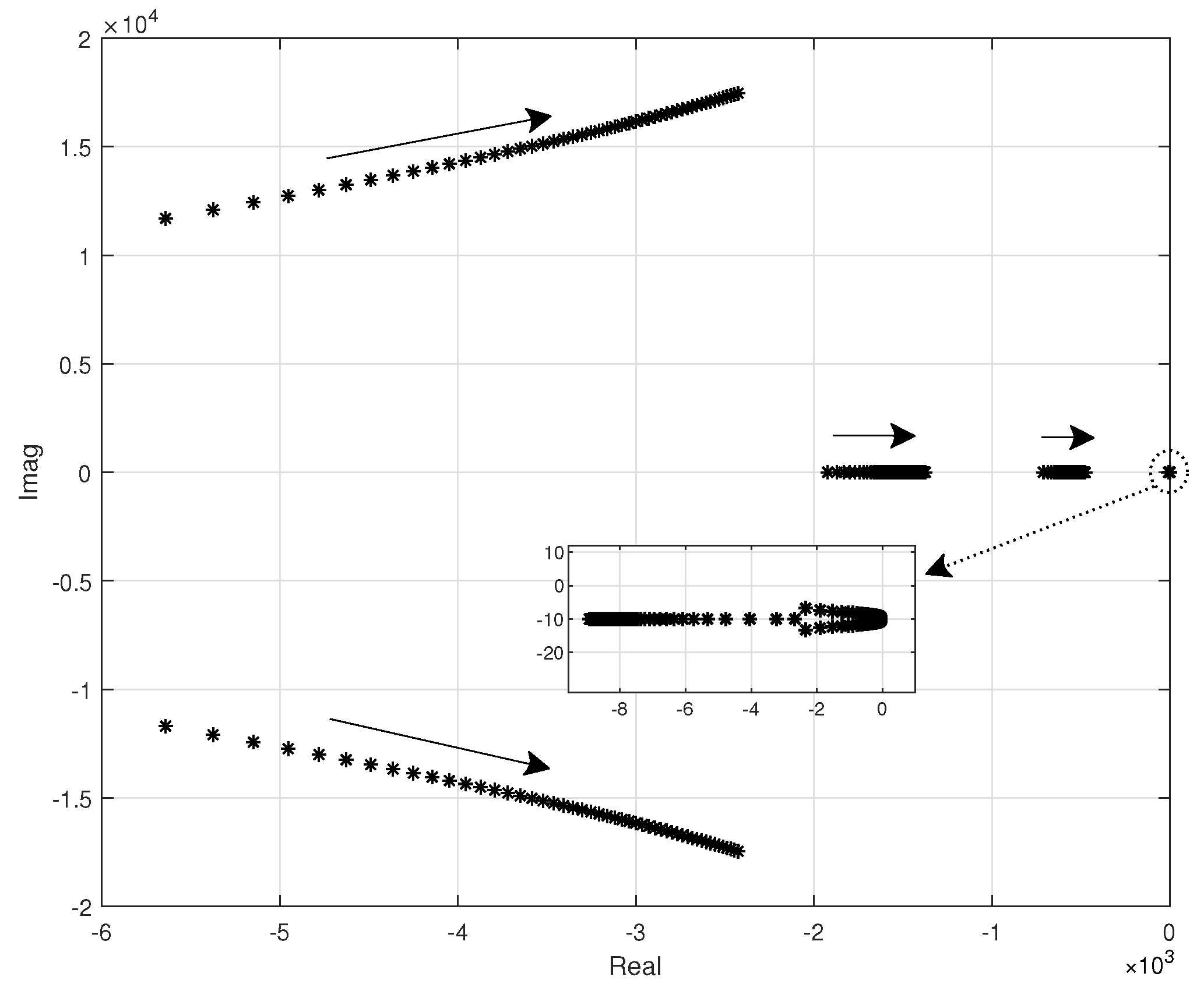
Figure 3 shows the root locus by varying virtual impedance
. It can be seen that the characteristic roots of matrix
A are all on the left half complex plane, hence, system can run steadily under the reasonable virtual impedance.
5. Simulation and Results
The simulation results using Matlab/Simulink were to verify the proposed secondary control strategy of the DC microgrid system, which are shown in
Figure 2. The system structure is described in
Section 2.1. The simulation parameters are listed in
Table 2. The system is comprised of four boost converters, four DC power sources, and DC loads, including a common load and local loads (10
, 20
, 30
, 40
, respectively).
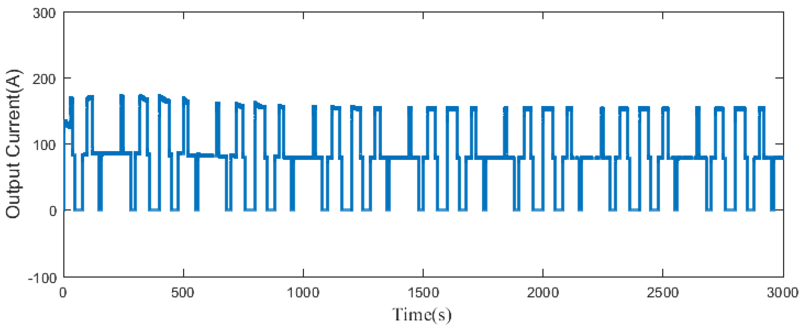
is the common load connected to four ESUs whose load fluctuations performance is shown in
Figure 4. During the period of 50–6000 s, the
is connected and disconnected periodically. In this simulation, the current sharing ratios
in (
18) were set 1, 1, 2, and 2 for ESU1–4, respectively.
Each ESU can communicate with the neighbor via a low band communication network. Simulation results are presented in
Figure 5,
Figure 6,
Figure 7 and
Figure 8.
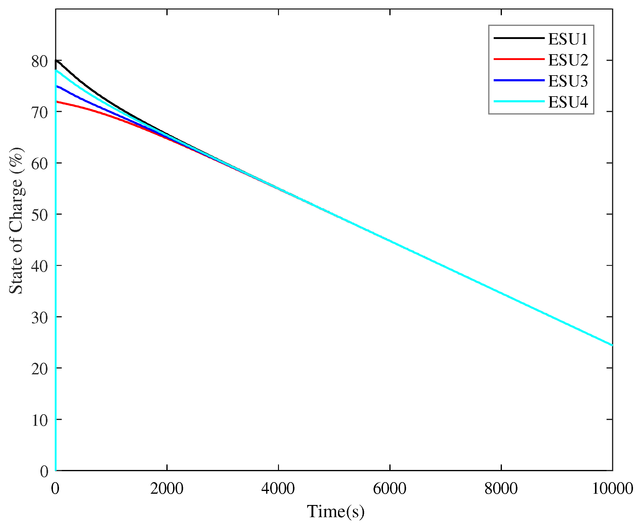
Figure 5 represents the simulation result of the SOC level of four ESUs.
Figure 6 represents the simulation result of the output current using a current sharing controller.
Figure 7 represents the results of output voltages with conventional (a) and proposed (b)controller, respectively. And
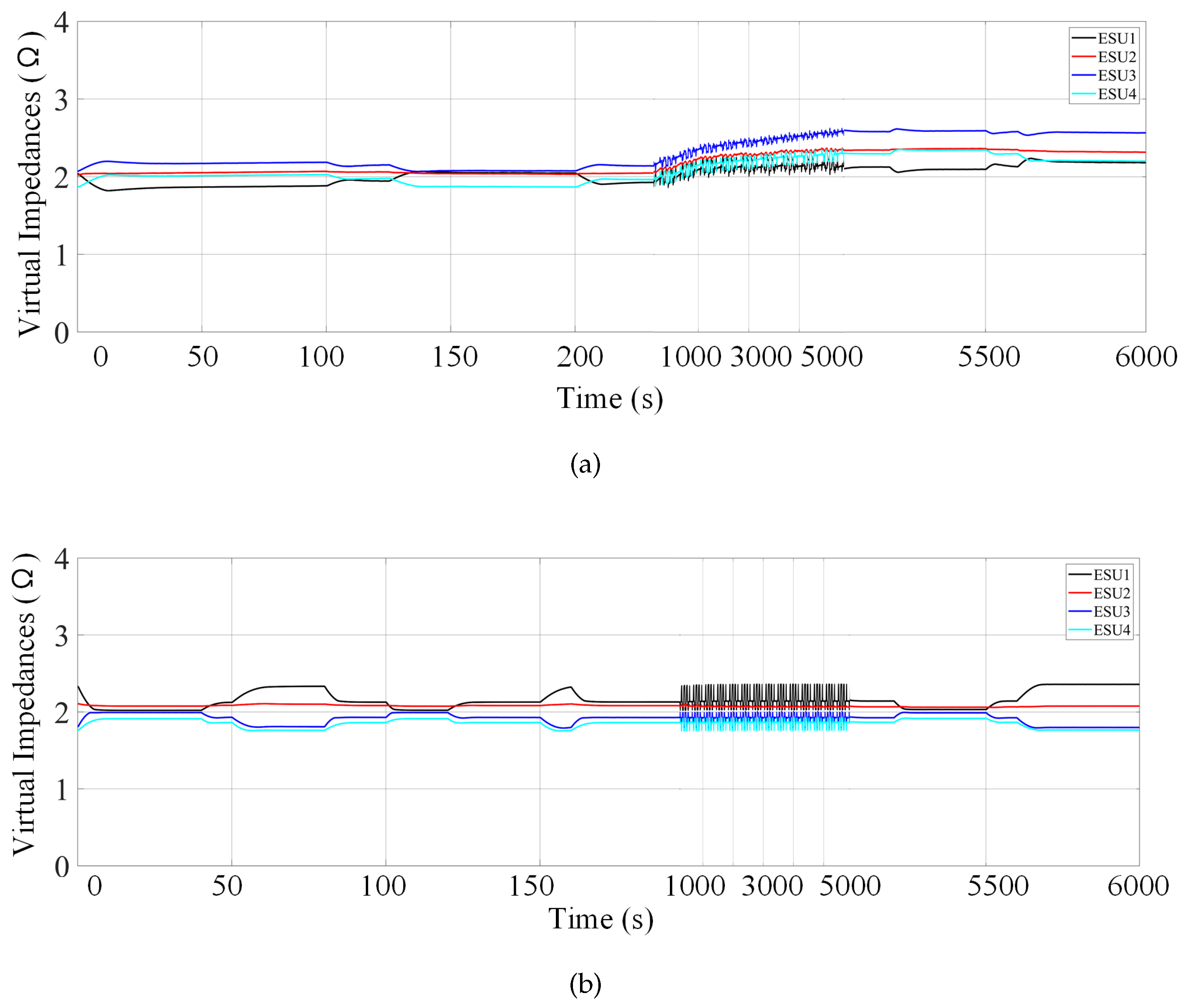
Figure 8 represents the results of virtual impedances with conventional (a) and proposed (b)controller. The simulation time is 6000 s, which is divided into three timing phases, i.e., 0–1000 s, 1000–5000 s, and 5000–6000 s.
The result of SOC with the proposed method is presented in
Figure 5. It can be seen the initial values of SOC1, SOC2, SOC3, SOC4 were
,
,
, and
, respectively. When the simulation began, the ESUs with higher SOC gave more power, while the lower one gave less. So the difference between SOCs of every ESU gradually became smaller, and eventually trended toward balance (at about 2000 s), thereby equalizing the state of charge of each ESU. This strategy is effective in cases where the initial SOC is different.
Before the implementation of secondary control, the output currents of four units are different. When proposed controllers are activated, the voltage deviation is gradually decreased, and the output current of each ESU can be accurately shared. From
Figure 6, the output currents of ESU 1 and 2 change from 53.56 to 80.56 A, and ESU 3 and 4 change from 106.74 to 160.16 A. Therefore, the proportional current sharing can be achieved, and the simulation results correspond to the current sharing ratio
1:1:2:2 for ESU 1–4.
The output voltages can be ensured to operate at the reference value because of the proposed control strategies, which show in
Figure 7b. At 3000 s, the output voltages are 785.4, 792.6 V, 807.9, and 815.1 V with the proposed method. Without the local voltage controller, the voltages cannot be restored to the reference value compares with
Figure 7b.
The differences between
Figure 8a,b have shown the droop coefficient with the conventional controller, and the proposed controller performs differently at the steady-state. From
Figure 8a we can see that the virtual impedances of four ESUs change a lot with the conventional controller. At 250 s, the virtual impedances were 2.18
, 2.05
, 1.96
, and 1.92
; they changed to 2.60
, 2.36
, 2.34
, and 2.12
. The upward trend was continuing at the end of
Figure 8a, and it could not reach a steady state. However, from
Figure 8b, the virtual impedances with the proposed controller operate stably, the values of which at the steady state were 2.14
, 2.06
, 1.92
, and 1.87
.
The simulation results between the conventional way and proposed method including the theoretical and the measured values, verify the improved control method performs better than the conventional one.
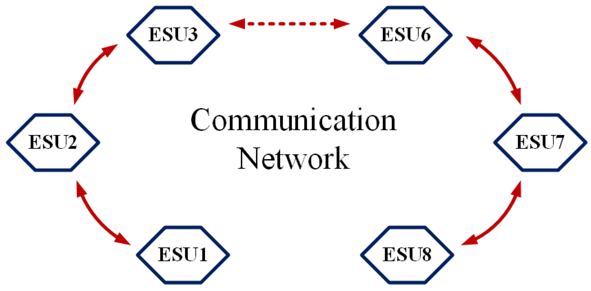
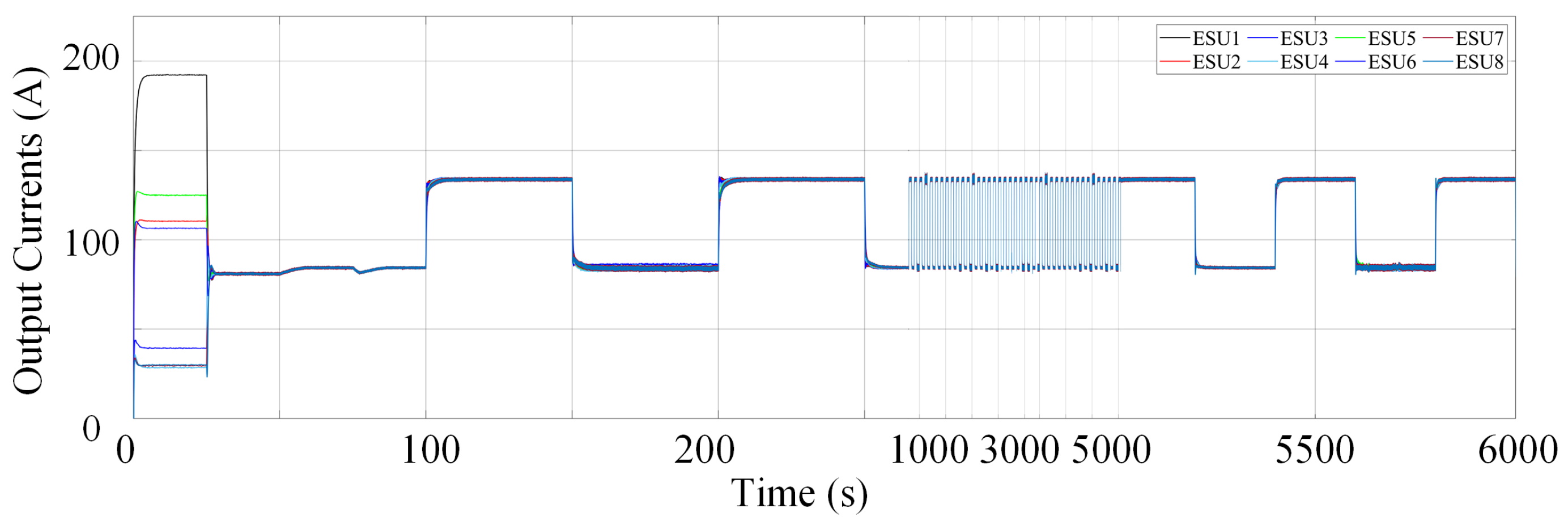
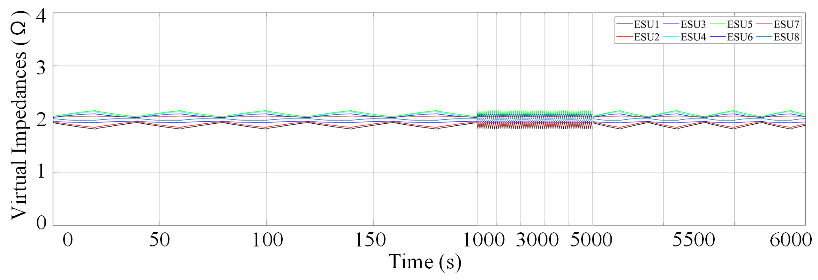
In order to further validate the reliability of the proposed model, we also adopted a large distribution network with eight ESUs and DC loads, including a common load and local loads using neighbor-to-neighbor communication, as shown in
Figure 9. Simulation results are presented in
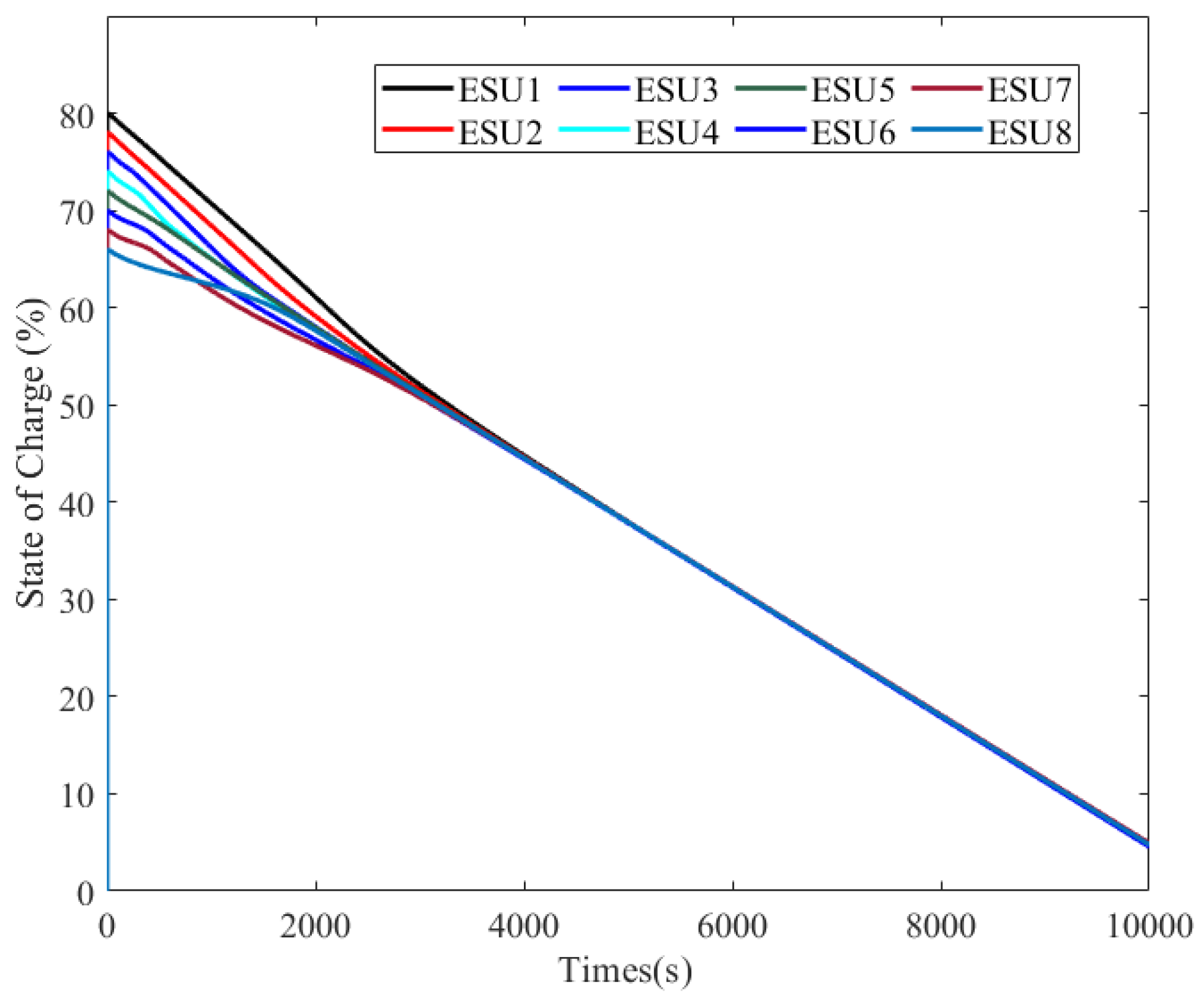
Figure 10,
Figure 11,
Figure 12 and
Figure 13 which are the results of SOC, output current, output voltage, and virtual impedances for each ESU. In this simulation, the output current sharing ratio
was set to 1 for each ESU. The simulation time was 6000 s, which was divided into three timing phases; i.e., 0–1000 s, 1000–5000 s, and 5000–6000 s. From the simulation results, it can be seen that SOC balancing and output current sharing can be achieved, the output voltages can be ensured to operate at the reference value, and the virtual impedances can operate stably with the proposed strategy. Hence, the effectiveness of the proposed method is proven.
