Thermodynamic Analysis of Advanced Gas Turbine Combined Cycle Integration with a High-Temperature Nuclear Reactor and Cogeneration Unit


Abstract
1. Introduction
2. Mathematical Model and Assumptions
3. Results and Discussion
4. Conclusions
Author Contributions
Funding
Conflicts of Interest
Abbreviations
| SMR | Small Modular Reactors |
| HTR | High-Temperature Reactor |
| HRSG | Heat Recovery Steam Generator units |
| GT | Gas Turbine |
| ST | Steam Turbine |
| Symbols | |
| Tout | Reactor outlet temperature (K) |
| Tin | Reactor inlet temperature (K) |
| Ti | Working fluid temperature at point i (K) |
| hi | Working fluid enthalpy at point i (MJ) |
| pi | Working fluid pressure at point i (MPa) |
| Helium mass flow rate (kg/s) | |
| Steam mass flow rate (kg/s) | |
| Water mass flow rate (kg/s) | |
| Helium specific heat (J/kgK) | |
| Qr, | Reactor thermal power (MW) |
| η | Cycle thermal efficiency |
| ηi | Steam turbine isentropic efficiency |
| ηip | Pump isentropic efficiency |
| ηmech | Generator mechanical efficiency |
| ηgen | Generator electrical efficiency |
| ηiGT | Gas turbine isentropic |
| ηmechGT | Gas turbine mechanical efficiency |
| ηiC | Compressor isentropic efficiency |
| Gas turbine work (MJ) | |
| Compressor work (MJ) | |
| Pumps work (MJ) | |
| Steam turbine electrical power (MW) | |
| Gas turbine electrical power (MW) | |
| Fan energy demand (MW) | |
| Pumps energy demand (MW) | |
References
- van der Westhuizen, S. World Energy Resources Coal; World Energy Council: London, UK, 2016. [Google Scholar]
- IAEA Nuclear Energy. Opportunities for Cogeneration with Nuclear Energy Series; NP-T-4.1. STI/PUB/1749; IAEA Nuclear Energy: Vienna, Austria, 2017. [Google Scholar]
- Méndez-Vigo, I.; García Peña, F. Puertollano IGCC Plant: Operating experience and potential for further technology development. In Proceedings of the POWER-GEN Europe, Brussels, Belgium, 29–31 May 2001. [Google Scholar]
- Jaszczur, M.; Dudek, M.; Rosen, M.A.; Kolenda, Z. An analysis of integration of a power plant with a lignite superheated steam drying unit. J. Clean. Prod. 2020, 243, 1–14. [Google Scholar] [CrossRef]
- Jaszczur, M.; Rosen, M.A.; Śliwa, T.; Dudek, M.; Pieńkowski, L. Hydrogen production using high temperature nuclear reactors: Efficiency analysis of a combined cycle. Int. J. Hydrog. Energy 2016, 41, 7861–7871. [Google Scholar] [CrossRef]
- World Energy Council. World Energy Resources; World Energy Council: London, UK, 2016. [Google Scholar]
- Urbanucci, L.; D’Ettorre, F.; Testi, D. A Comprehensive Methodology for the Integrated Optimal Sizing and Operation of Cogeneration Systems with Thermal Energy Storage. Energies 2019, 12, 875. [Google Scholar] [CrossRef]
- Carrero, M.M.; Sanchez, I.R.; De Paepe, W.; Parente, A.; Contino, F. Is There a Future for Small-Scale Cogeneration in Europe? Economic and Policy Analysis of the Internal Combustion Engine, Micro Gas Turbine and Micro Humid Air Turbine Cycles. Energies 2019, 12, 413. [Google Scholar] [CrossRef]
- International Energy Agency. Energy Technology Perspectives; International Energy Agency: Paris, France, 2015. [Google Scholar]
- Jaskólski, M.; Reński, A.; Minkiewicz, T. Thermodynamic and economic analysis of nuclear power unit operating in partial cogeneration mode to produce electricity and district heat. Energy 2017, 141, 2470–2483. [Google Scholar] [CrossRef]
- Elektrownia Jądrowa a Konwencjonalna. Energetyka Cieplna I Zawodowa; WNT: Warszawa, Poland, 2005. [Google Scholar]
- Mitenkov, F.M.; Kusmartsev, E.V. Nuclear Heat Applications in Russia: Experience, status and prospects. OKB Mech. Eng. 1998, 29, 291–312. [Google Scholar]
- Dudek, M.; Kolenda, Z.; Jaszczur, M.; Stanek, W. Thermodynamic Analysis of Power Generation Cycles with High-Temperature Gas-Cooled Nuclear Reactor and Additional Coolant Heating Up to 1600 °C. J. Energy Resour. Technol. 2018, 140, 020910. [Google Scholar] [CrossRef]
- Terazi, R.; Kurt, E. Improving the Efficiency of a Nucler Power Plant Using a Thermoelectric Cogeneration System. Int. J. Renew. Energy Dev. 2018, 7, 77–84. [Google Scholar] [CrossRef]
- Jaszczur, M.; Dudek, M.; Kolenda, Z. Numerical investigation of advanced gas turbine combined cycle coupled with high-temperature nuclear reactor and cogeneration unit. E3s Web Conf. 2019, 128, 03005. [Google Scholar] [CrossRef]
- Nuclear Energy Agency. On the Role and Economics of Nuclear Cogeneration in a Low Carbon Energy Future; Nuclear Energy Agency: Paris, France, 2012. [Google Scholar]
- Jędrzejewski, J.; Hanuszkiewicz-Drapała, M. Analyses of the Efficiency of a High-Temperature Gas-Cooled Nuclear Reactor Cogeneration System Generating Heat for the Sulfur–Iodine Cycle. J. Energy Resour. Technol. 2018, 140, 112001. [Google Scholar] [CrossRef]
- Hanuszkiewicz-Drapała, M.; Jędrzejewski, J. Thermodynamic analysis of a co-generation system with a high-temperature gas cooled nuclear reactor. J. Power Technol. 2015, 95, 32–41. [Google Scholar]
- Atkinson, S.; Litskevich, D.; Merk, B. Variable Reactivity Control in Small Modular High Temperature Reactors Using Moderation Manipulation Techniques. Energies 2018, 11, 1897. [Google Scholar] [CrossRef]
- Pieńkowski, L.; Jaszczur, M.; Dudek, M.; Skolik, K. CCGT and small nuclear SMR hybrids system for flexible energy generation. E3s Web Conf. 2019, 108, 01023. [Google Scholar] [CrossRef]
- Hirota, N.; Terada, A.; Yan, X.; Tanaka, K. A Concept of Intermediate Heat Exchanger for High-Temperature Gas Reactor Hydrogen and Power Cogeneration System. Next Generation Nuclear Plant Research and Development Program Plan. In Proceedings of the 2018 26th International Conference on Nuclear Engineering, London, UK, 22–26 July 2018. [Google Scholar]
- Zhou, X.; Tang, Y.; Lu, Z.; Zhang, J.; Liu, B. Nuclear graphite for high temperature gas-cooled reactors. New Carbon Mater. 2017, 32, 193–204. [Google Scholar] [CrossRef]
- McDonald, C.F. Power conversion system considerations for a high efficiency small modular nuclear gas turbine combined cycle power plant concept (NGTCC). Appl. Eng. 2014, 73, 82–103. [Google Scholar] [CrossRef]
- Zuoyi, Z.; Dong, Y.; Li, F. The Shandong Shidao Bay 200 MWe high-temperature gas-cooled reactor pebble-bed module (HTR-PM) demonstration power plant: An engineering and technological innovation. Engineering 2016, 2, 112–118. [Google Scholar]
- Luo, C.; Zhao, F.; Zhang, N. A novel nuclear combined power and cooling system integrating high temperature gas-cooled reactor with ammonia–water cycle. Energy Convers. Manag. 2014, 87, 895–904. [Google Scholar] [CrossRef]
- Locatelli, G.; Mancini, M.; Todeschini, N. Generation IV nuclear reactors: Current status and future prospects. Energy Policy 2013, 61, 1503–1520. [Google Scholar] [CrossRef]
- Jaszczur, M.; Dudek, M.; Kolenda, Z. Thermodynamic analysis of high temperature nuclear reactor coupled with advanced gas turbine combined cycle. Therm. Sci. 2019, 4, 1187–1197. [Google Scholar] [CrossRef]
- Marsden, B.; Fok, S.L.; Hall, G. High temperature gas-cooled reactor core design future material consideration. In Proceedings of the International Conference on Global Environment and Advanced Nuclear Power Plants (GENES4/ANP2003), Kyoto Research Park, Kyoto, Japan, 15–19 September 2003. [Google Scholar]
- Mylavarapu, S.K.; Sun, X.; Glosup, R.E.; Christensen, R.N.; Patterson, M.W. Thermal hydraulic performance testing of printed circuit heat exchangers in a high-temperature helium test facility. Appl. Eng. 2014, 65, 605–614. [Google Scholar] [CrossRef]
- Benato, A.; Bracco, S.; Stoppato, A.; Mirandola, A. Dynamic simulation of combined cycle power plant cycling in the electricity market. Energy Convers. Manag. 2016, 107, 76–85. [Google Scholar] [CrossRef]
- Bentivoglio, F.; Tauveron, N. Validation of CATHARE2 against OBERHAUSEN II data. Nucl. Technol. 2008, 164, 55–75. [Google Scholar] [CrossRef]
- Saez, M.; Tauveron, M.; Chataing, T.; Geffraye, G.; Briottet, L.; Alborghetti, N. Analysis of the turbine deblading in an HTGR with the CATHARE code. Nucl. Eng. Des. 2006, 236, 574–586. [Google Scholar] [CrossRef]
- Verkerk, E.C.; Kikstra, J.F. Comparison of two models for a high temperature reactor coupled to a gas turbine. Nucl. Eng. Des. 2003, 220, 51–65. [Google Scholar] [CrossRef]
- Li, Y.; Zhang, G.; Bai, Z.; Song, X.; Wang, L.; Yang, Y. Backpressure adjustable gas turbine combined cycle: A method to improve part-load efficiency. Energy Convers. Manag. 2018, 74, 739–754. [Google Scholar] [CrossRef]
- Benato, A.; Bracco, S.; Stoppato, A.; Mirandola, A. LTE: A procedure to predict power plants dynamic behavior and components lifetime reduction during transient operation. Appl. Energy 2016, 162, 880–891. [Google Scholar] [CrossRef]
- Benato, A.; Stoppato, A.; Mirandola, A. Dynamic behavior analysis of a three pressure level heat recovery steam generator during transient operation. Energy 2015, 90, 1595–1605. [Google Scholar] [CrossRef]
- Dudek, M.; Jaszczur, M. An analysis of the thermodynamic cycles with high-temperature nuclear reactor for power generation and hydrogen co-production. E3s Web Conf. 2017, 14, 1–12. [Google Scholar] [CrossRef]
- Jaszczur, M.; Dudek, M.; Śliwa, T.; Kolenda, Z. An analysis of high-temperature nuclear reactor coupled with gas turbine combined cycle. Matec. Web Conf. 2018, 240, 05010. [Google Scholar] [CrossRef]
- Dudek, M.; Podsadna, J.; Jaszczur, M. An numerical analysis of high-temperature helium reactor power plant for co-production of hydrogen and electricity. J. Phys. Conf. Ser. 2016, 745, 032009. [Google Scholar] [CrossRef]
- Dudek, M.; Jaszczur, M.; Skolik, K.; Malicki, M.; Pieńkowski, L. High-temperature nuclear reactor power plant cycle for hydrogen and electricity production–numerical analysis. E3s Web Conf. 2016, 10, 1–6. [Google Scholar] [CrossRef]
- Dudek, M. An Analysis of the Thermodynamic Cycles with High Temperature Nuclear Reactor, Application for Power Generation, Cogeneration, Hydrogen Production and Industrial Application. Ph.D. Thesis, AGH University of Science and Technology, Kraków, Poland, 2018. [Google Scholar]
- Promes, E.J.O.; Woudstra, T.; Schoenmakers, L.; Oldenbroek, V.; Thattai, A.T.; Aravind, P.V. Thermodynamic evaluation and experimental validation of 253 MW Integrated Coal Gasification Combined Cycle power plant in Buggenum, Netherlands. Appl. Energy 2015, 155, 181–194. [Google Scholar] [CrossRef]


| BWR | PWR | RMBK | CANDU | HTR | SFR | |
|---|---|---|---|---|---|---|
| Power (MW) | 600 | 600/1650 | 1200/1500 | 600/880 | 300/600 | 1000/3000 |
| Fuel (% 235U) | 2.6 | 3.2 | 2(2.2) | 0.72 | 10 | 20 (Pu/U) |
| Core dimensions (m) | 3.7 × 3.7 | 3.0 × 3.7 | 11.8 × 7 | 7.1 × 5.9 | 9.8 × 6 | 12 × 16.5 |
| Reactor outlet temperature (K) | 558 | 588 | 557 | 583 | 1023 | 823/833 |
| Reactor pressure (MPa) | 7.6 | 15.0 | 4.7 | 8.6 | 4.8 | 0.1 |
| Steam temperature (K) | 548 | 543–563 | 553 | 533 | 843 | 728 |
| Steam pressure (MPa) | 6.2 | 4–6 | 6.5 | 4.7 | 17 | 15.2 |
| Thermal efficiency (%) | 32–34 | 32–35 | 31 | 30 | >40 | 40 |
| System Configuration | System Configuration | System Configuration |
|---|---|---|
| 1P-HRSG heat recovery system | 2P-HRSG heat recovery system | 3P-HRSG heat recovery system |
| Inter-stage steam superheated system with 1P-HRSG heat recovery system | Inter-stage steam superheated system with 2P-HRSG heat recovery system | Inter-stage steam superheated system with 3P-HRSG heat recovery system |
| Steam regeneration system with 1P-HRSG heat recovery system | Steam regeneration system with 2P-HRSG heat recovery system | Steam regeneration system with 3P-HRSG heat recovery system |
| System with a steam regeneration and inter-stage steam superheat with 1P-HRSG | System with a steam regeneration and inter-stage steam superheat with 2P-HRSG | System with a steam regeneration and inter-stage steam superheat with 3P-HRSG |
| Thermodynamic equations for heat exchanger (IHX) | |||
| p4 = p3 − dp34N | t4 = DTN |  | h4 = f(p4,T4) |
| m4 = m3 | Q4 = m4h4 | dQ = Q3 − Q4 | |
| p2 = p1 − Dp12N | Q2 = Q1 + dQ | m2 = m1 | |
| h2 = Q2/m2 | T2 = f(p2,h2) | DTLO = T4 − T1 | |
| DTUP = T3 − T2 | LMTD = (DTUP-TLO)/(ln(DTUP)-ln(DTLO)) | KAN = DQ/LMTD | |
| Thermodynamic equations for compressor |  | ||
| m2 = m1 | s1 = f(p1,T1) | t2S = f(p2,s1) | |
| h2s = f(p2,T2S) | dhS = h2S − h1 | dh = dhS/ETAI | |
| h2 = h1 + dh | t2 = f(p2,h2) | Q2=m2h2 | |
| h3 = (m2h2 − m1h1)/(m3ETAM) | V1 = f(p1,T1) | Vm1 = m1v1 | |
| Thermodynamic equations for Gas Turbine (GT) | |||
| P1 = P1N * (ETAI/ETAIN) = f(m1/m1N) | ETAI = (ETAI/ETAIN) * ETAIN |  | m2 = m1 |
| s1 = f(p1,T1) | t2S = f(p2,s1) | h2S = f(P2,T2S) | |
| Dh = dhsETAI | h2 = h1 − dh | T2 = f(p2, h2) | |
| Q2 = m2h2 | Q = (m1h1 − m2h2) * ETAMN | P1 = P1NF | |
| h4 = (Q + m3h3FAC)/m4 | F = m1/m1NSqrt((T1+273.14)/(T1N +273.14)) | ||
| Thermodynamic equations for Steam Turbine (ST) | |||
| x1 = f(p1,h1) | s1 = f(p1,h1) |  | V1 = f(p1,h1) |
| Vm1 = m1v1 | s2S = s1 | h2S = f(p2,s2S) | |
| dhS = h1 − h2S | FAK = m1/m1N | ETAI=ETAIN * f(FAK) | |
| FAK = (p1/p2)/(p1N/p2N) | ETAI = ETAIN * f(FAK) | FAK = Vm1/Vm1N | |
| ETAI = ETAIN * f(FAK) | dh2L = dh2LN | FAK = Vm2/Vm2N | |
| dh2L = dh2LN * FAK2} | dh = dhs * ETAI | h2 = h1 − dh + dh2L | |
| x2 = f(p2,h2) | T2 = f(p2,h2) | m1 = m2 + m3 + m4 | |
| p3 = p2 | T3 = T2 | h3 = h2 | |
| Q3 = m3h3 | p4 = p2 | T4 = T2 | |
| h4 = h2 | Q4 = m4h4 | ||
| Thermodynamic equations for evaporator | |||
| p8 = p6 = p5 = p2 = p1 | T2 = T5 = T6 = T8 = fsat(p1) |  | T1 = T2 − TAPPN |
| h1 = f(p1,T1) | h2 = fsat(p2,T2,x = 1) | h5 = fsat(p5,T5,X = 0) | |
| s6 = f(p6,T6) | p7 = p6 + dp12N | h7S = f(p7,s6) | |
| dhs = h7S-h6 | dh = dhs/ETAIN | h7 = h6 + dh | |
| t7 = f(p7,h7) | p4 = p3 − dp34N | T4 = T7 + PINPN | |
| h4 = f(p4,T4) | m4 = m3 | Q3 = m3h3 | |
| Q4 = m4h4 | QN = Q3 − Q4 | Q87 = (Q3 − Q4)(1 − DQLR) | |
| m2h2 − m1h1 + m5h5 − QPUM = Q87 | m6 = m2CN | m1 = m2 + m5 | |
| QPUM = m6dh | DTLO = T4 − T7 | m8 = m7 = m6 | |
| m2 = (Q87 − m5 * (h5 − h1))/(h2 − h1 − CN * dh) | KAN = dQ/LMTD | DTUP = T3 − T8 | |
| Q7 = m7h7 | KANLMTD = (m3h3 − m4h4)(1 − DQLR) | ||
| LMTD = (DTUP − DTLO)/(ln(DTUP) − ln(DTLO)) | KANLMTD = m8h8 − m7 * h7 | ||
| Thermodynamic equations for deareator |  | ||
| F = (m3/m3N)2 | dp32 = dp32NF | p2 = p3 − dp32 | |
| T2 = f’(p2) | h2 = f(p2,T2) | m2 = m1 + m3 + m4 − m5 | |
| Q2 = m2h2 | p5 = p2 = p1 = p4 | T5 = T2 | |
| h5 = f”(T5) | q5 = m5h5 | m3 = ((m2h2 − m1h1 − m4h4 + m5h5))/h3 | |
| Thermodynamic equations for pump | |||
| s1 = f(p1,h1) | T2S = f(p2,s1) |  | h2S = f(p2,s1) |
| h2 = h1 + dhdhs = h2S − h1 | Fluid Oil: dhs = 0.1(p2 − p1)/ρ | m2 = m1 v1 = 1/ρ | |
| vm1 < mINFLOW | RCIRC = MINFLOW/vm1 | RCIRC = 1 | |
| dHEAD = 100000(p2 − p1) * v1/9.81 | RZHF = f(dHEAD/SOH) | dh = dhs/ETAI | |
| vm1 = RZHFZHF | m1 = vm1/(RCIRCv1) | RCIRC = 1 | |
| FCALC = 1 i FSPEC = 1 | ETAI = ETAINf(m1/m1N) | dHEAD = f(vm1) | |
| p2 = p1 + 9.81 * dHEAD/v1 * 0.00001 | h3 = (m2h2 − m1h1)RCIRC/ETAM | ||
| Thermodynamic equations for condenser |  | ||
| K = 6.47878 * (441.325mm − dTUBEAU) * SQRT(UW) * CT * CM * CLTUBE | KA = k * ATUBE | ||
| UW = dx(1)/(ρ * NTUBE * 3.141592 * (DTUBEIN/2)) | CPW = CPW(PX(1),TX(1)) | ||
| RHOW = 1/SPEZVOL(px(1),TX (1)) | |||
| CT = 1.395-EXP(-TX(1)/22.61°C) − (TX(1) − 21°C)/166°C | |||
| Parameter name | Value | Unit |
|---|---|---|
| HTR thermal power | 300 | MWth |
| Primary loop—working fluid | He | - |
| Secondary loop—working fluid | He | - |
| Primary loop—mass flow rate of helium | 128 | kg/s |
| Inlet pressure before Gas Turbine | 6.95 | MPa |
| HTR outlet temperature | 850 | °C |
| HTR coolant pressure | 7 | MPa |
| Outlet pressure after GT | 2 | MPa |
| Secondary loop—mass flow rate of helium | 104.5 | kg/s |
| Temperature of outlet water from condenser | 24.0 | °C |
| Pressure inlet at feedwater preheater | 0.5/0.9 | bar |
| ST inlet temperature | 385 | °C |
| ST inlet pressure | 20.5 | MPa |
| GT isentropic/mechanical efficiency | 0.9/0.99 | - |
| ST isentropic/mechanical efficiency | 0.88/0.998 | - |
| Generator electric efficiency | 0.986 | - |
| System Configuration | Electricity Production (MWe) | Production of Heat Energy (MWth) | Energy Self-Consumption (MW) | Thermal Efficiency (%) | |
|---|---|---|---|---|---|
| Gas Turbine | Steam Turbine | ||||
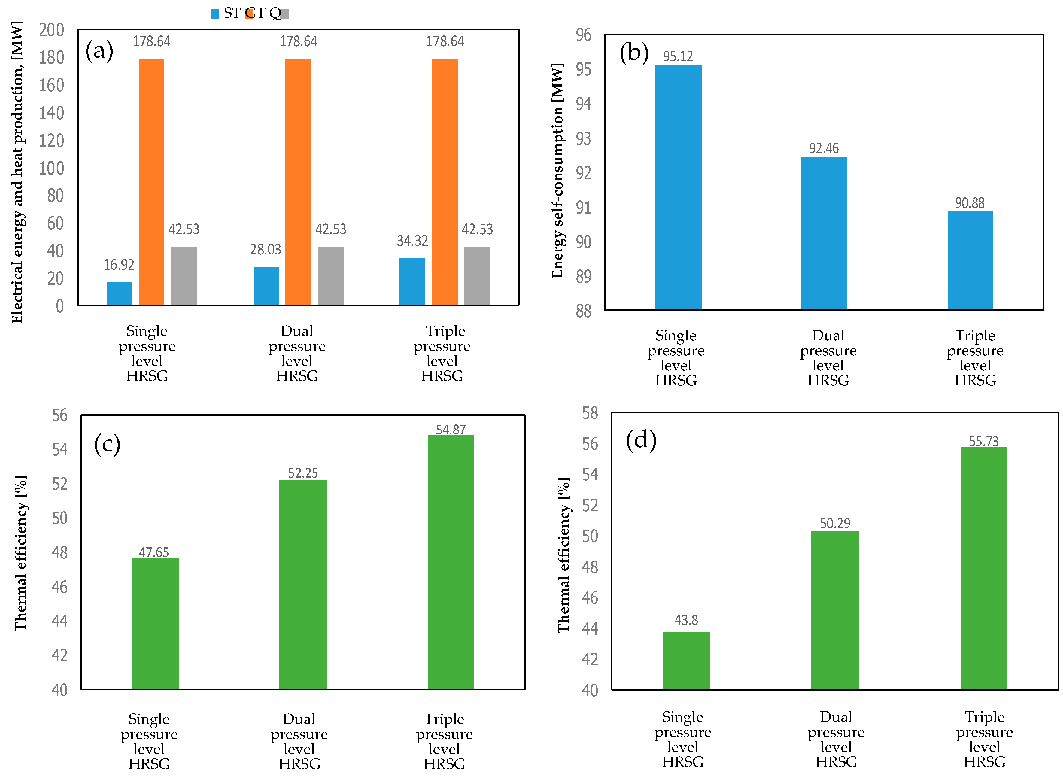
| 1P-HRSG heat recovery system | 16.9 | 42.5 | 95.1 | 47.6 | |
| 2P-HRSG heat recovery system | 28.0 | 42.5 | 92.4 | 52.2 | |
| 3P-HRSG heat recovery system | 34.3 | 42.5 | 90.9 | 54.8 | |
| inter-stage steam superheated system with 1P-HRSG heat recovery system | 17.9 | 31.5 | 96.8 | 43.8 | |
| inter-stage steam superheated system with 2P-HRSG heat recovery system | 22.9 | 42.6 | 93.2 | 50.2 | |
| inter-stage steam superheated system with 3P-HRSG heat recovery system | 35.4 | 42.6 | 89.5 | 55.7 | |
| steam regeneration system with 1P-HRSG heat recovery system | 178.6 | 15.6 | 42.5 | 93.8 | 47.6 |
| steam regeneration system with 2P-HRSG heat recovery system | 25.9 | 42.5 | 89.0 | 52.6 | |
| steam regeneration system with 3P-HRSG heat recovery system | 35.5 | 42.5 | 87.9 | 56.2 | |
| with a regeneration system and inter-stage steam superheat with 1P-HRSG | 17.5 | 30.4 | 96.0 | 43.5 | |
| with a regeneration system and inter-stage steam superheat with 2P-HRSG | 22.4 | 41.1 | 92.1 | 50.0 | |
| with a regeneration system and inter-stage steam superheat with 3P-HRSG | 34.3 | 39.3 | 87.6 | 54.9 | |
© 2020 by the authors. Licensee MDPI, Basel, Switzerland. This article is an open access article distributed under the terms and conditions of the Creative Commons Attribution (CC BY) license (http://creativecommons.org/licenses/by/4.0/).
Share and Cite
Jaszczur, M.; Dudek, M.; Kolenda, Z. Thermodynamic Analysis of Advanced Gas Turbine Combined Cycle Integration with a High-Temperature Nuclear Reactor and Cogeneration Unit. Energies 2020, 13, 400. https://doi.org/10.3390/en13020400
Jaszczur M, Dudek M, Kolenda Z. Thermodynamic Analysis of Advanced Gas Turbine Combined Cycle Integration with a High-Temperature Nuclear Reactor and Cogeneration Unit. Energies. 2020; 13(2):400. https://doi.org/10.3390/en13020400
Chicago/Turabian StyleJaszczur, Marek, Michał Dudek, and Zygmunt Kolenda. 2020. "Thermodynamic Analysis of Advanced Gas Turbine Combined Cycle Integration with a High-Temperature Nuclear Reactor and Cogeneration Unit" Energies 13, no. 2: 400. https://doi.org/10.3390/en13020400
APA StyleJaszczur, M., Dudek, M., & Kolenda, Z. (2020). Thermodynamic Analysis of Advanced Gas Turbine Combined Cycle Integration with a High-Temperature Nuclear Reactor and Cogeneration Unit. Energies, 13(2), 400. https://doi.org/10.3390/en13020400