Article

Experimental Study on a Flue Gas Waste Heat Cascade Recovery System under Variable Working Conditions

1
College of Resources, Shandong University of Science and Technology, Tai’an 271019, China
2
School of Energy and Power Engineering, Shandong University, Jinan 250061, China
3
Shandong Provincial Key Laboratory of Civil Engineering Disaster Prevention and Mitigation, College of Civil Engineering and Architecture, Shandong University of Science and Technology, Qingdao 266590, China
4
National Engineering Laboratory for Coalmine Backfilling Mining, Shandong University of Science and Technology, Tai’an 271019, China
*
Authors to whom correspondence should be addressed.
Energies 2020, 13(2), 324; https://doi.org/10.3390/en13020324
Submission received: 23 December 2019 / Revised: 4 January 2020 / Accepted: 7 January 2020 / Published: 9 January 2020
(This article belongs to the Section A: Sustainable Energy)

Abstract

:
Recovering flue gas waste heat is beneficial to improving the unit efficiency in power plants. To obtain the change rules of performance parameters of a flue gas waste heat cascade recovery system (FWCRS) under variable working conditions, an experiment bench was designed and built. The variation laws of the inlet temperature and exhaust flue gas temperature of a low temperature economizer (LTE), the inlet and outlet air temperature of an air preheater (AP), the heat exchange quantities of the AP, LTE, and front-located air heater and an additional economizer (AE), as well as the waste heat recovery efficiency, the system exergy efficiency, and the energy grade replacement coefficient were obtained as the flue gas flow, flue gas temperature, bypass flue gas ratio, air temperature, and circulating water flow in AE changed. Using an orthogonal test, the flue gas temperature, bypass flue gas ratio and air temperature were proved to be the significant factors affecting the performance parameters of FWCRS, and the bypass flue gas ratio was suggested as an adjusting parameter of FWCRS under variable working conditions.

1. Introduction

With the rapid development of the world economy and increase of the population, the demand for energy sources is growing. In China, most of the electricity still comes from coal-fired power plants, and about half of the produced coal was consumed by thermal power stations over the past decade [1], which brings about greenhouse effect, environmental pollution, and other issues. Despite non-fossil energy being used as much as possible, coal-fired power will still occupy a dominant position in the foreseeable future in China [2]. Reducing coal consumption and improving coal use efficiency on the existing coal-fired units are very necessary for solving the above problems.
For coal-fired power plant units, the exhaust flue gas temperature of boilers can reach more than 120 °C, and about 50–80% of boiler heat loss is due to the exhaust flue gas energy loss, which accounts for 3–8% total energy input of the units [3]. To reduce exhaust heat loss, reducing exhaust flue gas temperature is one of the effective measures to decrease coal consumption and improve unit efficiency, and the temperature can be reduced by recovering the waste heat from high-temperature flue gas. The recovered flue gas waste heat is generally used to heat condensed water from condenser, heat boiler feed water, or preheat air for coal combustion in boilers on coal-fired units [4,5,6,7,8,9], as well as used for drying boiler fuel, waste heat power generation, seawater desalination, organic Rankine cycle, etc. [10,11,12,13,14]. The waste heat in sulfur-reduced flue gas can also be recovered by absorption heat pump to save energy and reduce pollution emissions [15].
The flue gas waste heat is usually recovered by heat exchangers located at tail flue of power plant boilers. Wang [16] assessed the coal-saving effect of a 600 MW unit installed a low pressure economizer (LPE) in three cases, and 2–4 g/(kW·h) standard coal was saved. Xu [17] proposed a novel flue gas waste heat recovery system, in which a low temperature economizer (LTE) was located between a high-temperature air preheater (AP) and a low temperature AP, and 5.6 MW of exergy destruction was saved. Stevanovic [18] studied the unit efficiency improvement when a high pressure economizer (HPE) used for recovering flue gas waste heat was supplied cold or hot feed water on an aged 620 MW coal-fired unit, and the case of HPE fed with cold water proved to be competitive. To recover more waste heat effectively from flue gas, many flue gas waste heat depth use systems were put forward and analyzed. The systems were more complex and can heat feed water and combustion air at the same time. Han [19] proposed a new heat integration system, 4 g/(kW·h) standard coal was saved by adding a steam-air heater on a bypass flue gas waste heat recovery system of a 1000 MW unit. Yan [20] optimized a bypass flue gas waste heat use system on a 1000 MW unit by recovering waste heat from flue gas after wet flue gas desulphurization, the net standard coal consumption was reduced 5.38 g/(kW·h). Fan [21] developed a cascade energy use system by combining flue gas waste heat recovery and bleeding steam energy use, the net efficiency of a double reheat cycle was improved 0.61%. Yang [22] proposed a conceptual waste heat recovery system on a 1000 MW coal-fired unit, in which the AP was divided into high-temperature AP, main AP and low temperature AP, the flue gas waste heat was used to heat condensed water by LTE and heat the combustion air by the APs, and 13.3 MW additional net power output was produced. The above-mentioned flue gas waste heat use systems all have good energy-saving and coal-saving effects; however, the analysis of energy-saving effects of the systems were based only on rated conditions, without analyzing the systems’ performance under variable working conditions.
The performance of flue gas waste heat recovery system under off-design conditions was also studied in the literature. Song [23] used the thermodynamic analysis method to study the off-design operating performance of an LTE system, and the results indicated that the energy-saving effect of the system was stable under high-load conditions. Song [24] also analyzed the energy-saving effect of a deep waste heat use system on a 1000 MW ultra-supercritical unit under variable operating conditions by thermodynamic calculation, and the result showed that the energy-saving effect of the unit was obviously reduced under low-load conditions. Zhang [25] studied the energy-saving potential of an exhaust gas heat recovery system on a 600 MW unit by developing a calculation model of steam turbine and heat exchangers under off-design conditions, and the ratio of bypass flue gas was proved to have the greatest influence on the saved coal amount of the unit. Han [26] simulated the thermal efficiency of a lignite-fired 600 MW unit with a flue gas drying and waste heat use system, and the improvement of plant thermal efficiency was reduced from 1.51% to 1.36% as the operating condition changed from benchmark condition to 50% full load condition. The dynamic model of heat exchangers used for waste heat use and large scale coal-fired power plants were also studied in the literature [27,28]. However, in the study of the performance of the waste heat use systems under variable conditions mainly focused on model analysis, theoretical calculations, and simulation calculations, little experimental research was conducted, and the influence of operating parameters on performance of waste heat use system has not been studied experimentally.
The flue gas from coal-fired boiler generally contains acid gases such as SO2 and NOx, the water vapor in the flue gas will condense and form solution, which may cause corrosion, ash deposit and fouling on the tail flue and heat exchanger surface, affecting the safe and reliable operation of the unit [29,30,31,32]. Therefore, the exhaust flue gas temperature of flue gas waste heat recovery system should not be reduced too much before desulfurization, generally reduced to about 80 °C [33].
During the operation of the power station unit, the unit load often changes due to the influence of electricity demand, the operation of the flue gas waste heat recovery system may deviate from the design working condition and run under variable working conditions, and the flue gas waste heat recovery effect will be affected. To obtain better waste heat recovery effect and guide the operation and regulation of flue gas waste heat recovery system, studying the variation laws of performance parameters of the system under variable operating conditions is necessary. However, as the operating parameters of a flue gas waste heat recovery system may affect system performance and cannot be adjusted arbitrarily on an actual unit, it is difficult to obtain the operating rules of the system by on-site test.
In this study, an experimental bench was built to study the variation laws of performance parameters such as the inlet flue gas temperature and exhaust flue gas temperature of an LTE, the inlet and outlet air temperature of an AP, the heat exchange quantity of the AP, LTE, front-located air heater (FAH) and additional economizer (AE), the waste heat recovery efficiency, the system exergy efficiency, and the energy grade replacement coefficient of a flue gas waste heat cascade recovery system (FWCRS) as the flue gas flow, flue gas temperature, bypass flue gas ratio, air temperature, and circulating water flow in AE changed, and the main factors affecting the performance parameters of FWCRS were determined by orthogonal test. The obtained experimental results can provide a reference for the operation adjustment of actual units.

2. Experimental Section

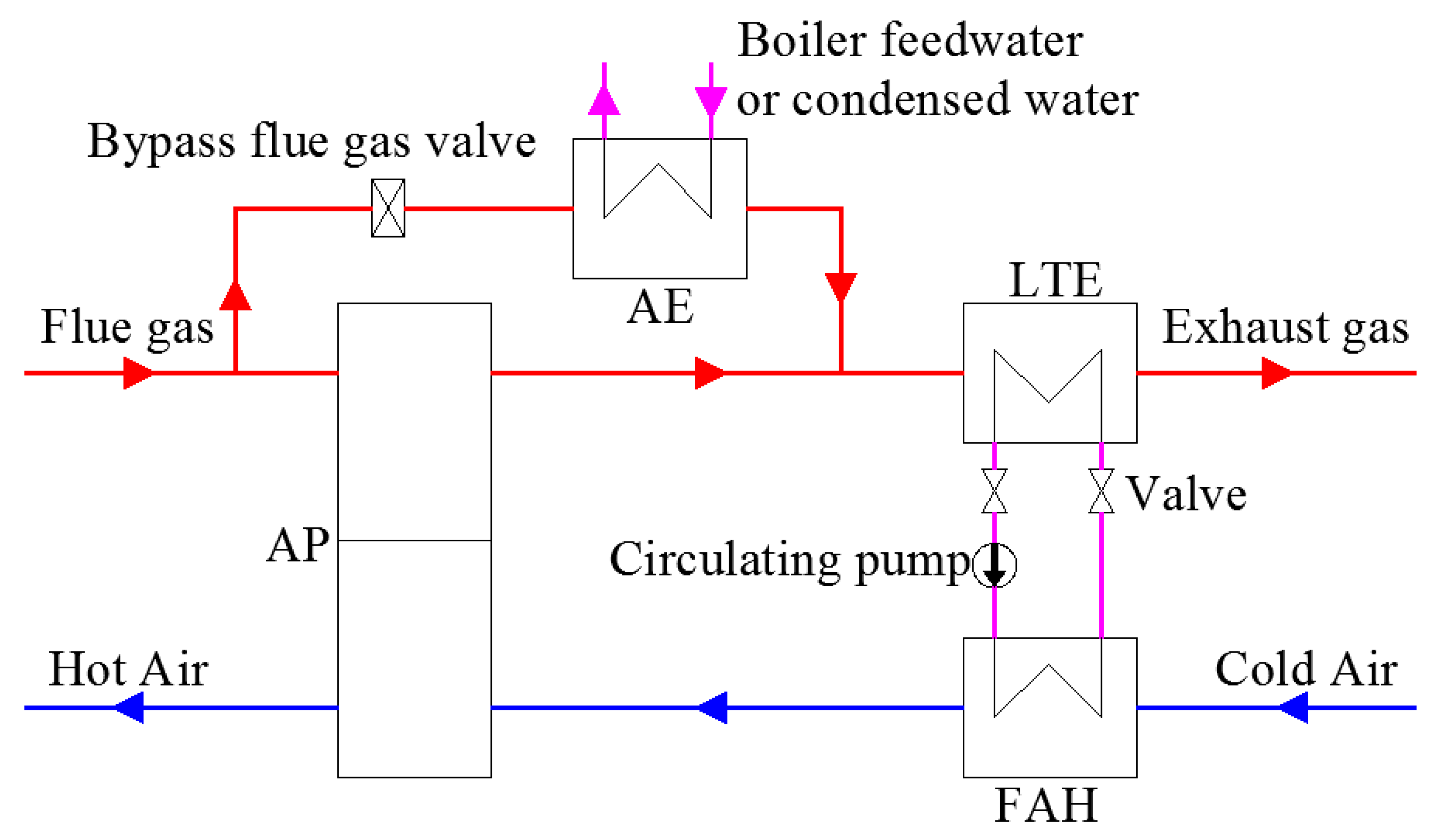
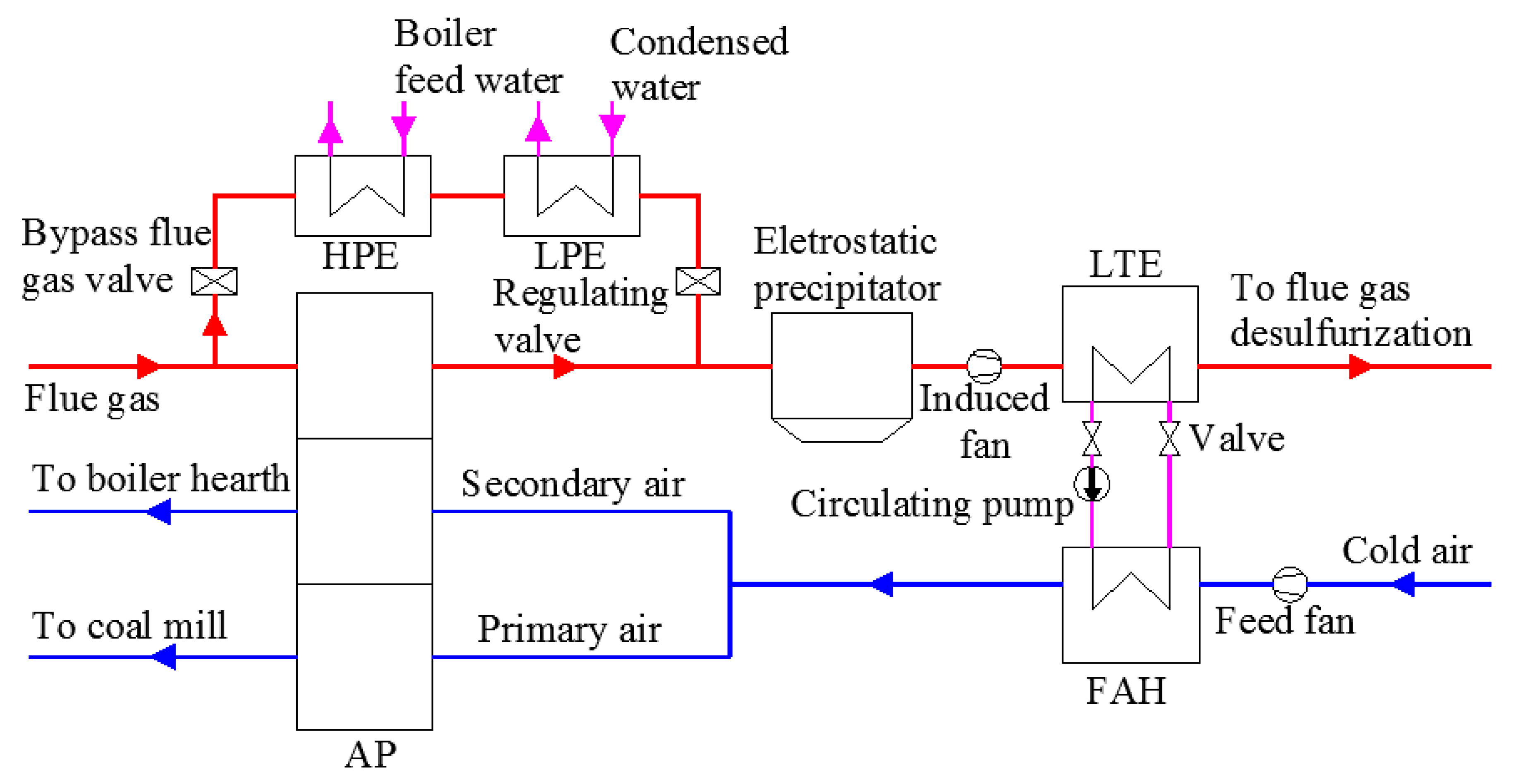
2.1. Description of FWCRS

FWCRS is a flue gas waste heat depth use system. The technical process of the system is shown in Figure 1. Most of the high-temperature exhaust flue gas from boiler economizer flows through an AP to heat combustion air, and small part of flue gas passes through an AE to heat boiler feed water or condense water. After the two parts of flue gas are cooled down, the low temperature flue gas merges into an LTE to heat circulating medium. Then, the heated medium enters into a FAH to heat the air flowing into the AP. In the system, the high-temperature flue gas is used to heat the boiler feed water or condensed water with matching temperature, the low temperature flue gas is used to heat the air with matching temperature by LTE-FAH system, the cascade recovery of exhaust flue gas is achieved.
The FWCRS has been applied to a 1000 MW ultra-supercritical double reheat coal-fired unit [34]. The technical process of the system is displayed in Figure 2 [35]. Up to 30% of high-temperature flue gas flows through an HPE and an LPE in sequence to heat boiler feed water and condensed water respectively, and the bypass flue gas valve is used to adjust the flue gas flow. The rest flue gas flows through an AP and heat primary air and secondary air in it. Then the cooled flue gas flows through electrostatic precipitator and enters into an LTE with the action of an induced fan. In an LTE, the low temperature flue gas heats the circulating medium and enters into desulfurization process. A feed fan drives the cold air into a FAH, in which the air is heated by the heated circulating medium. Then the heated air is further heated in the AP. The primary air flows to coal mill, and the secondary air flows to boiler hearth.
In the process of flue gas heat use in Figure 2, the cold air is heated in the FAH by low energy grade flue gas waste heat transferred from the LTE, saving high energy grade flue gas heat. The saved heat is used to heat boiler feed water and condensed water, reducing the stream for heating the water, and the saved stream can be used to drive steam turbine to generate electricity. The unit efficiency is improved, and the coal consumption and exhaust gas temperature are reduced. When the air temperature meets the unit operation requirements, the more flue gas waste heat is recovered in HPE, LPE, and LTE, the higher is the unit efficiency. However, as the unit often operates under varying loads, the operating conditions of the FWCRS will also change. To guide the system operation adjustment and optimize system design, as well as to obtain higher waste heat use efficiency, it is necessary to study the operating performance of the system under variable working conditions.

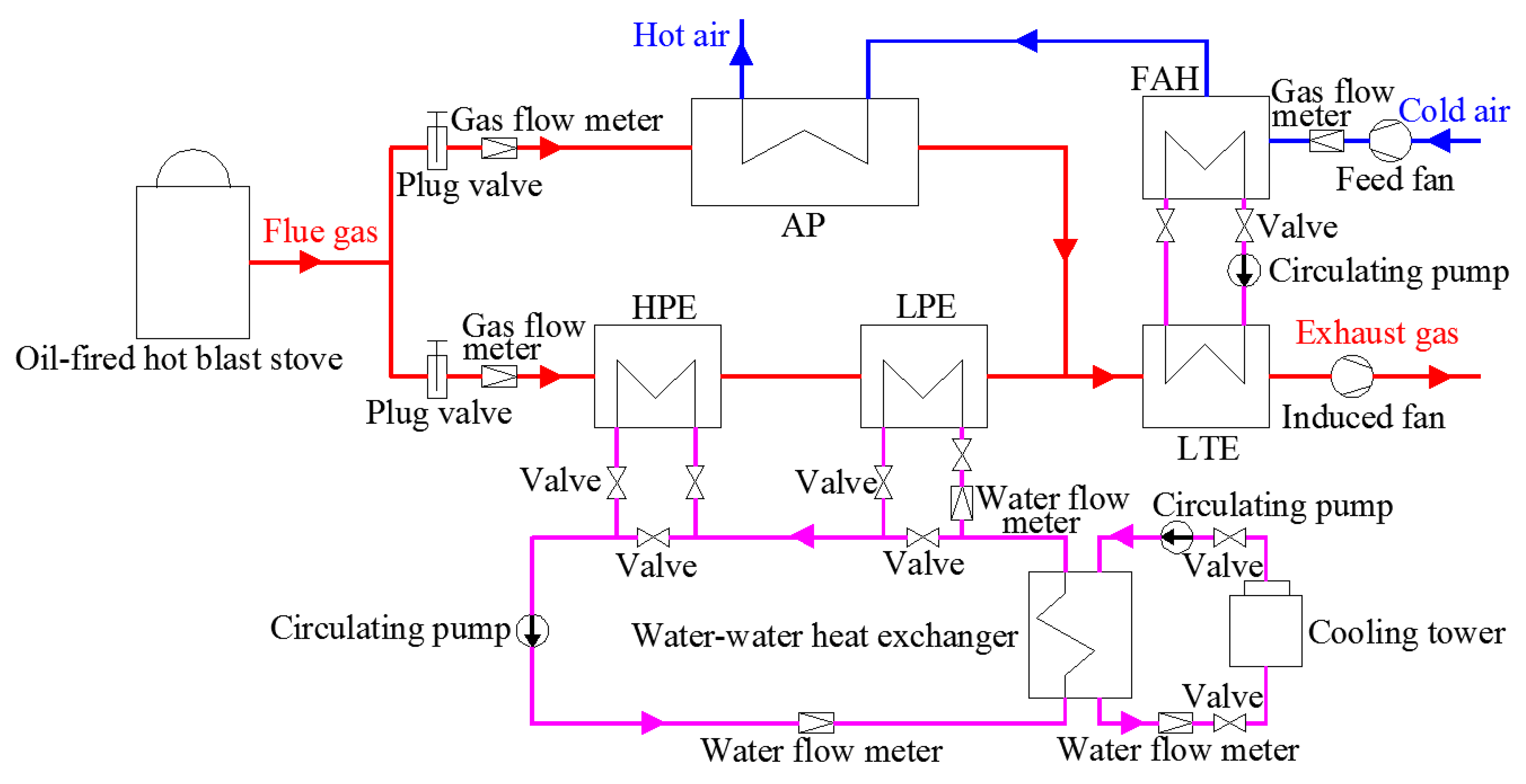
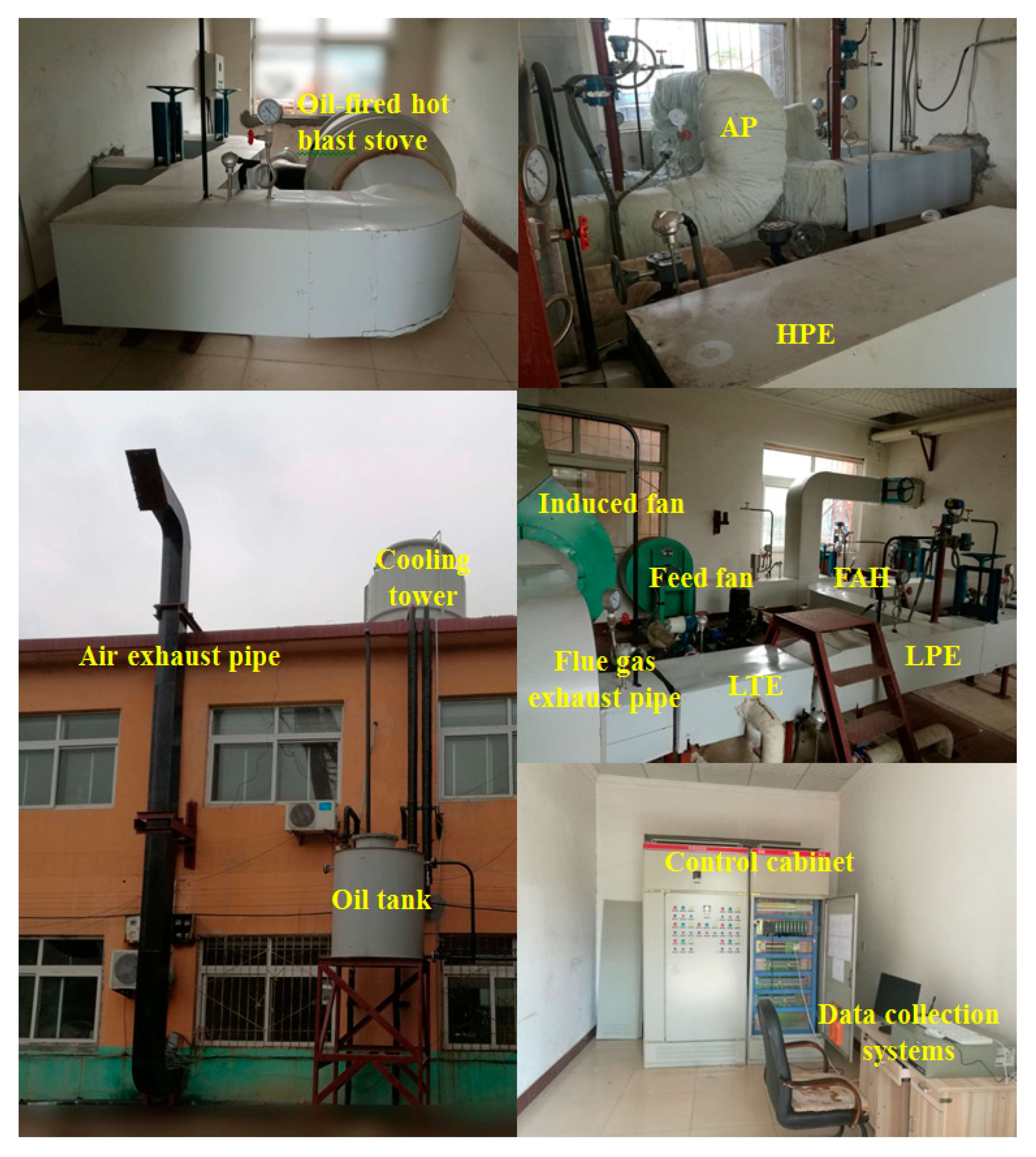
2.2. Experimental Setup

A prototype experimental bench was designed and built based on the technical process of the FWCRS in Figure 1 and the actual system on a 1000 MW double reheat ultra-supercritical coal-fired unit in Figure 2. The flow chart of the flue gas waste heat cascade recovery experimental bench is illustrated in Figure 3. The high-temperature flue gas was produced by a 465 kW oil-fired hot blast stove, and the stove fuel is diesel oil. The temperature and the flow of the flue gas can be adjusted by combustion control system. The initial design flue gas temperature was 400 °C. The hot flue gas entered into an AP and an AE in two ways, respectively. The AE consists of an HPE and an LPE, and they are double H-finned tube heat exchangers. The flue gas flew outside the tubes, and the circulating water flew inside the tubes. The AP is a spiral finned tube heat exchanger, in which the flue gas flew inside the tubes, and the air flew outside the tubes. The gas flow into the AP and AE can be adjusted by plug valves. The cooled flue gas mixed and flowed into an LTE. In an LTE, the flue gas exchanged heat with circulating medium water, and was further cooled and discharged by an induced fan. The inlet flue gas temperature and exhaust flue gas temperature of the LTE were set at 115 °C and 85 °C, respectively. The cold air was sent to FAH by a feed fan and heated by the circulating medium water from the LTE. The LTE and FAH are elliptical finned tube heat exchangers, in which the gas flew outside the tubes, and the circulating water flew inside the tubes. The LTE, FAH, circulating pipeline, and water pump make up an LTE-FAH system. In the system, the flue gas heat was transferred from the flue gas side to the air side by the circulating water. Then the heated air flowed into AP and was heated continuously. Finally, the hot air was discharged outside, and the outlet air temperature was set at 350 °C. The induced fan and the feed fan are centrifugal fans. Driven by a circulating pump, the circulating water entered into the LPE and HPE in sequence, and was heated by the high-temperature flue gas. The water flow into the HPE and LPE can be adjusted by valves on water pipeline. A water-water tube-shell heat exchanger was set on the circulation loop. On one side of the heat exchanger, the circulating water temperature was reduced to prevent vaporization. On the other side of the heat exchanger, a cooling tower was located on the roof of the laboratory and used to reduce the temperature of circulating water to ensure the safe operation of the system. The on-site layout of flue gas waste heat cascade recovery experimental bench is shown in Figure 4.

2.3. Data Acquisition and Processing

On the above experimental bench, the thermal resistances were set at the inlet and outlet of the heat exchangers to obtain the temperatures of the flue gas, air, and water. The gas flow meter and water flow meter were used to measure the flow of flue gas, air, and water, respectively. The measured data were all transmitted by an industrial switch typed X108 to an industrial computer typed IPC-610H in a control room for subsequent processing. The data acquisition system was set up based on WinCC software, and Origin software was used for data subsequent processing. The models and accuracies of the measuring instruments are displayed in Table 1. For every test condition, the data acquisition system collects data every minute. As all data fluctuations did not exceed 1%, five sets of data were selected for subsequent calculations. Affected by the accuracies of measuring instruments, the experimental parameters have uncertainties. Assuming the expression of the tested parameters is Y = f(x1, x2, …, xn), and x1, x2, …, xn are independent variables, the uncertainty transmission of the experimental parameter Y can be obtained using Equation (1).
σ Y = ( f x 1 ) 2 ( δ x 1 ) 2 + ( f x 2 ) 2 ( δ x 2 ) 2 + + ( f x n ) 2 ( δ x n ) 2
δ x = | Δ x | max x ¯ × 100 % = | x i x ¯ | max x ¯ × 100 %
Where σY is the uncertainty of Y, δx1, δx2, δxn are the relative errors of x1, x2, and xn, respectively, and can be calculated by Equation (2). |Δx|max, xi, x ¯ are the maximum absolute error, test value and average value of the measured x, respectively. In the experiment, the uncertainties of the calculated parameters are not more than 5%.

3. Performance Parameters of FWCRS

Under variable working conditions of FWCRS, the inlet and outlet temperature of each heat exchangers change constantly. Too low exhaust flue gas temperature may cause corrosion and ash fouling in the tail flue, and too high exhaust flue gas temperature will reduce the waste heat recovery efficiency. Too high or too low inlet combustion air temperature of boiler will affect the safe and reliable running of the unit. The inlet flue gas temperature of LTE is an important parameter affecting system efficiency [36]. The lower outlet air temperature of FAH may lead to ash deposit and corrosion in AP. Therefore, the exhaust flue gas temperature to,LTE and the inlet flue gas temperature ti,LTE of LTE, the outlet air temperature to,FAH of FAH, and the outlet air temperature to,AP of AP were studied as important operating parameters of FWCRS in the experiment. The temperatures can be measured using thermal resistances in the experiment.
For FWCRS, the heat exchange quantities of AP, AE, LTE, and FAH directly related to the flue gas waste heat recovery effect. The heat exchange quantities Q are also used as performance parameters of the system and are calculated using Equation (3).
Q = ρ G c p ( T 1 T 2 )
where Q is the heat exchange quantity of each heat exchangers, ρ is the density of flue gas, water, or air, G is the flow rate of flue gas, water, or air in unit time, cp is the specific heat of flue gas, water, or air, T1 and T2 are the initial temperature and final temperature of flue gas, water and air, respectively. The energy grade replacement coefficient ε is defined to evaluate the increase degree of energy grade of flue gas waste heat, which can be obtained using Equation (4).
ε = λ s λ r λ r
where ε is the energy replacement coefficient, λr is the energy grade of recovered low-grade flue gas waste heat, and λs is the energy grade of replaced high-grade flue gas waste heat. The energy grade of flue gas waste heat can be calculated by Equation (5) [36].
λ = E q = c ρ G ( T 1 T 2 T 0 ln T 1 T 1 ) c ρ G ( T 1 T 2 ) = 1 T 0 T 1 T 2 ln T 1 T 2
where λ is the energy grade of flue gas waste heat, E is the exergy released by flue gas, q is the heat released by flue gas, c is the average specific heat of flue gas, m is the flow of flue gas, T1 and T2 are the initial temperature and final temperature of flue gas, T0 is the ambient temperature.
According to Figure 2, the recovered flue gas waste heat is finally used to save steam for heating boiler feed water and condensate from condenser, improving the working capacity of the unit. The more flue gas waste heat is recovered, the more steam is saved. The waste heat recovery efficiency is used to evaluate the amount of the recovered waste heat. Due to the exergy loss caused by the irreversibility of energy conversion, the recovered waste heat cannot be completely converted into useful work. The exergy is defined as the available energy in the recovered waste heat that can be converted into work. The system exergy efficiency is introduced to evaluate the amount of the available energy in the input energy of FWCRS. The waste heat recovery efficiency ηr and the system exergy efficiency ηe of FWCRS are determined by the following Equations, respectively.
η r = Q AE + Q FAH Q f × 100 %
η e = E AE + E AP E f + W × 100 %
where ηr and ηe are the waste heat recovery efficiency and system exergy efficiency, respectively, Qf is the heat supplied by flue gas to the system, QAE is the heat released by flue gas in AE, QFAH is the heat obtained from the air from FAH, Ef is the exergy released by flue gas in FWCRS, EAE is the exergy obtained from the water in AE, EAP is the exergy obtained from the air in AP, W is the electric power consumption of fans and water pumps in FWCRS in unit time. In Equation (6), Qf, QAE, and QFAH are determined by Equation (3), EAE, and EAP are calculated by Equation (8) [36].
E = ρ G c p [ ( T 1 T 2 ) T 0 ln T 1 T 2 ]
where E is the exergy, ρ is the density of flue gas, water, or air, G is the flow rate of flue gas, water, or air in unit time, cp is specific heat of flue gas, water, or air, T1 and T2 are the initial temperature and final temperature of flue gas, water and air, respectively, T0 is ambient temperature.

4. Results and Discussion

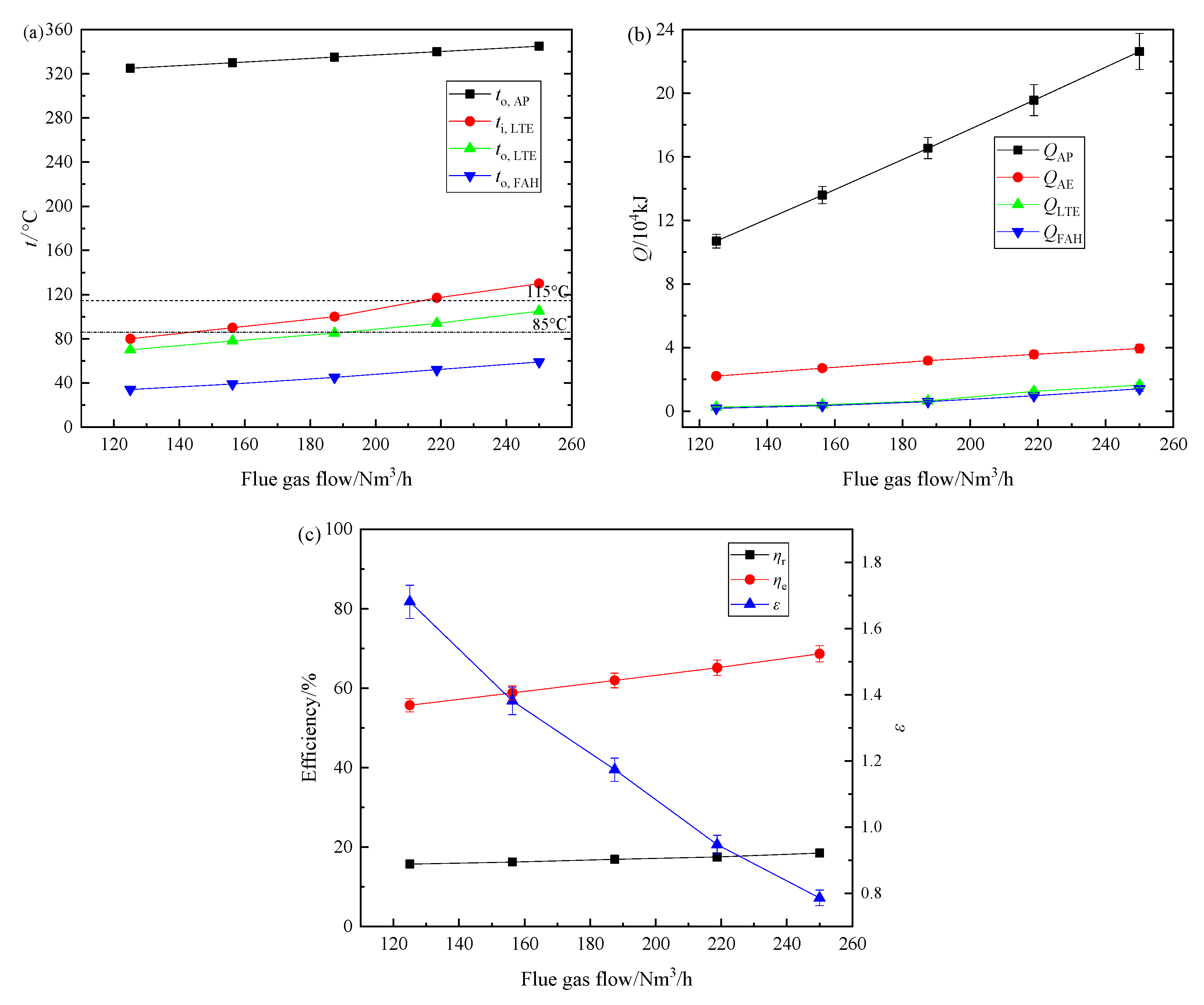
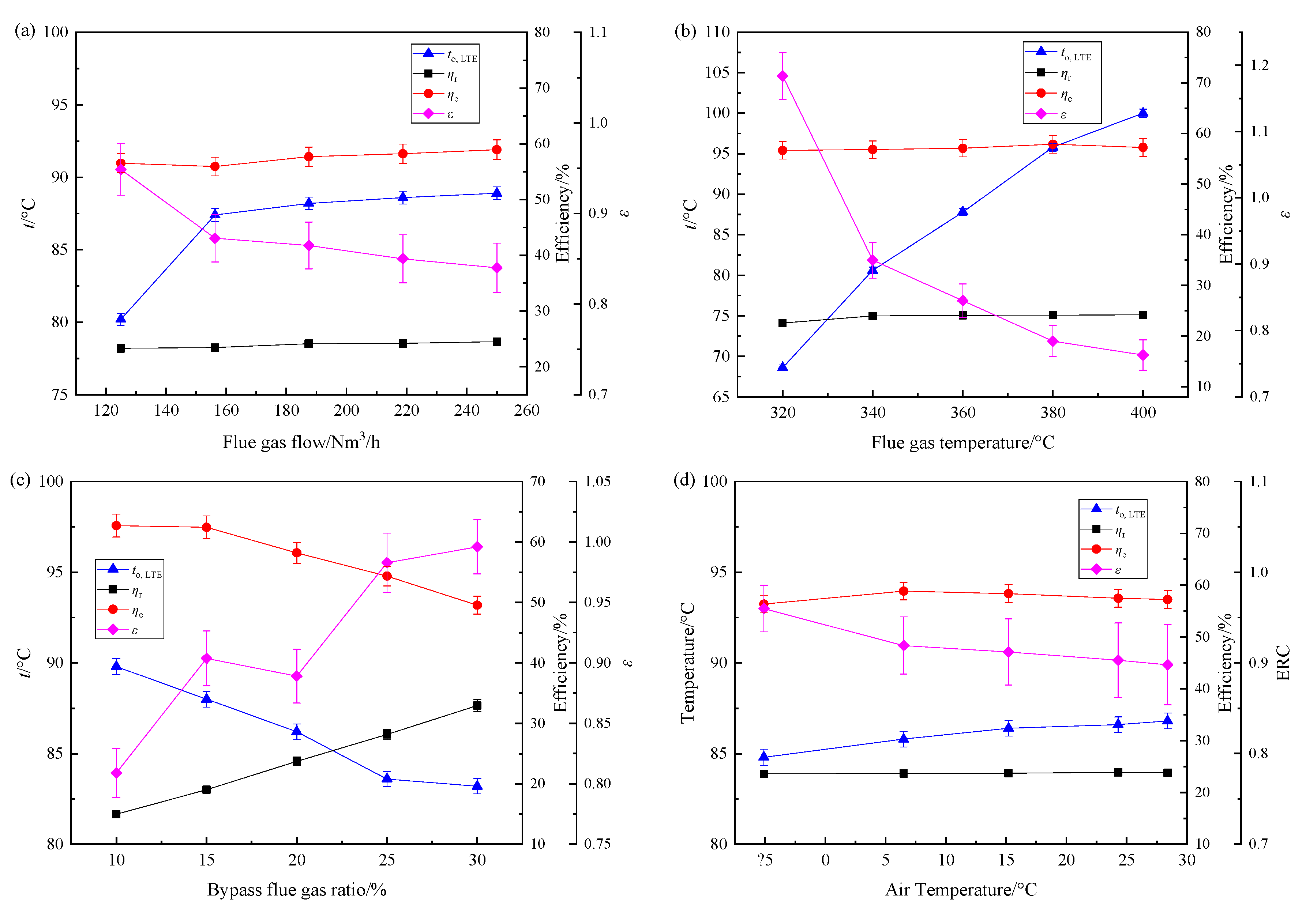
4.1. Effect of Flue Gas Flow on Performance Parameters of FWCRS

The flue gas temperature was set at 380 °C, the initial air temperature was 24.3 °C, and the bypass flue gas ratio was about 15% of the total flue gas flow. As the flue gas flow varied from 125 to 250 Nm3/h, the relationships between the flue gas flow and the performance parameters of FWCRS such as main node temperatures, heat exchange quantities of exchangers, waste heat recovery efficiency ηr, system exergy efficiency ηe, and energy grade replacement coefficient ε are shown in Figure 5 with error bars.
As shown in Figure 5a, with the flue gas flow increased, the outlet air temperature of AP, the inlet flue gas temperature of LTE, the outlet air temperature of FAH, and the exhaust flue gas temperature of LTE increased to different degrees. When the flue gas flow was about 220 Nm3/h, the inlet flue gas temperature of LTE was nearly 117 °C, slightly higher than the design temperature, the exhaust flue gas temperature was about 90 °C, higher than the design value, and the outlet air temperature of FAH and AP were close to the design conditions. The increasing flue gas flow led to higher exhaust flue gas temperature, and measures should be taken to reduce the temperature to improve waste heat recovery. Figure 5b indicates the heat exchange quantities of AP, AE, LTE, and FAH increased with the flue gas flow added. The heat exchange quantity of AP increased greatly because more high-temperature flue gas flowed across the AP. In Figure 5c, the waste heat recovery efficiency and system exergy efficiency increased slightly, which revealed the added flue gas flow was beneficial to improve waste heat recovery. However, the energy grade replacement coefficient decreased with the flue gas flow increased, the main reason was the increased exhaust flue gas temperature and inlet flue gas temperature of LTE reduced the energy grade improvement of flue gas waste heat. For an actual coal-fired unit, as the unit load rises, the flue gas flow increases, the variation of theoretical calculation results such as some node temperatures and heat exchange quantities of HPE and LPE on a 1000 MW unit in [24] is consistent with the experiment results. A large amount of flue gas flow will cause the exhaust flue gas temperature to increase. As the unit load rises, the FWCRS should be adjusted to reduce the exhaust flue gas temperature to ensure the waste heat recovery effect.

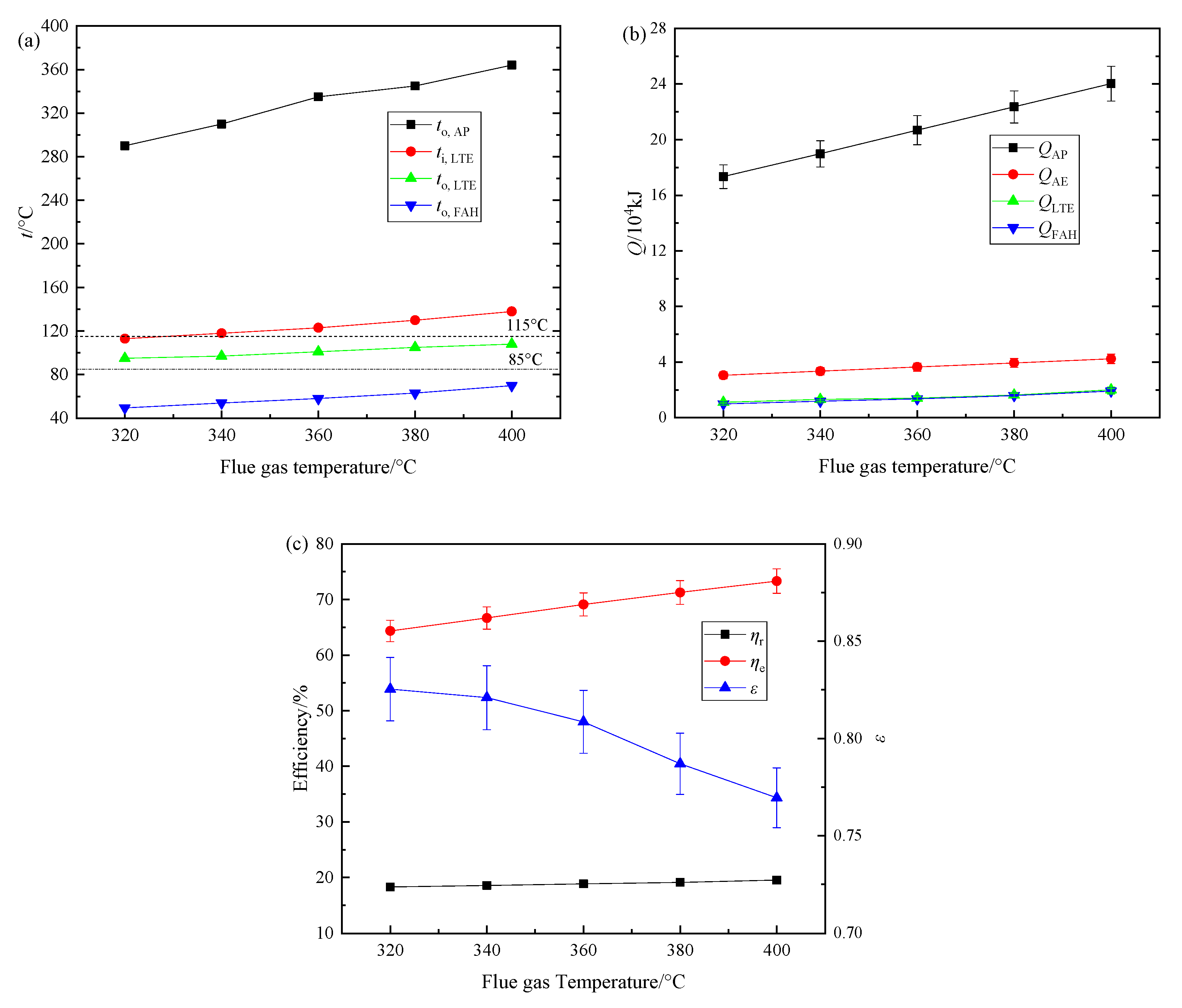
4.2. Effect of Flue Gas Temperature on Performance Parameters of FWCRS

The flue gas flow was set at 250 Nm3/h, the initial air temperature was 24.5 °C, and the bypass flue gas ratio was about 15% of the total flue gas flow. As the flue gas temperature varied from 320 °C to 400 °C, the relationship between the flue gas temperature and the performance parameters of FWCRS are displayed in Figure 6 with error bars.
In Figure 6, as the flue gas temperature rose, the main node temperatures, and the heat exchange quantities of the exchangers increased. The waste heat recovery efficiency and the system exergy efficiency rose, and the energy grade replacement coefficient decreased. The change trends of the parameters were basically the same as the trends when the flue gas flow was added. This is consistent with the actual operation of a power station unit. As the unit load increases, the flue gas flow and the flue gas temperature will increase at the same time, leading to the increased exhaust flue gas temperature and more heat recovery. However, excessive exhaust flue gas temperature will result in greater waste heat loss. As the flue gas temperature and flue gas flow increase, the FWCRS should be adjusted to transfer the flue gas waste heat to the boiler’s feed water and condensate as much as possible by AE to decrease the exhaust flue gas temperature and improve the waste heat use efficiency, saving more steam for power generation.

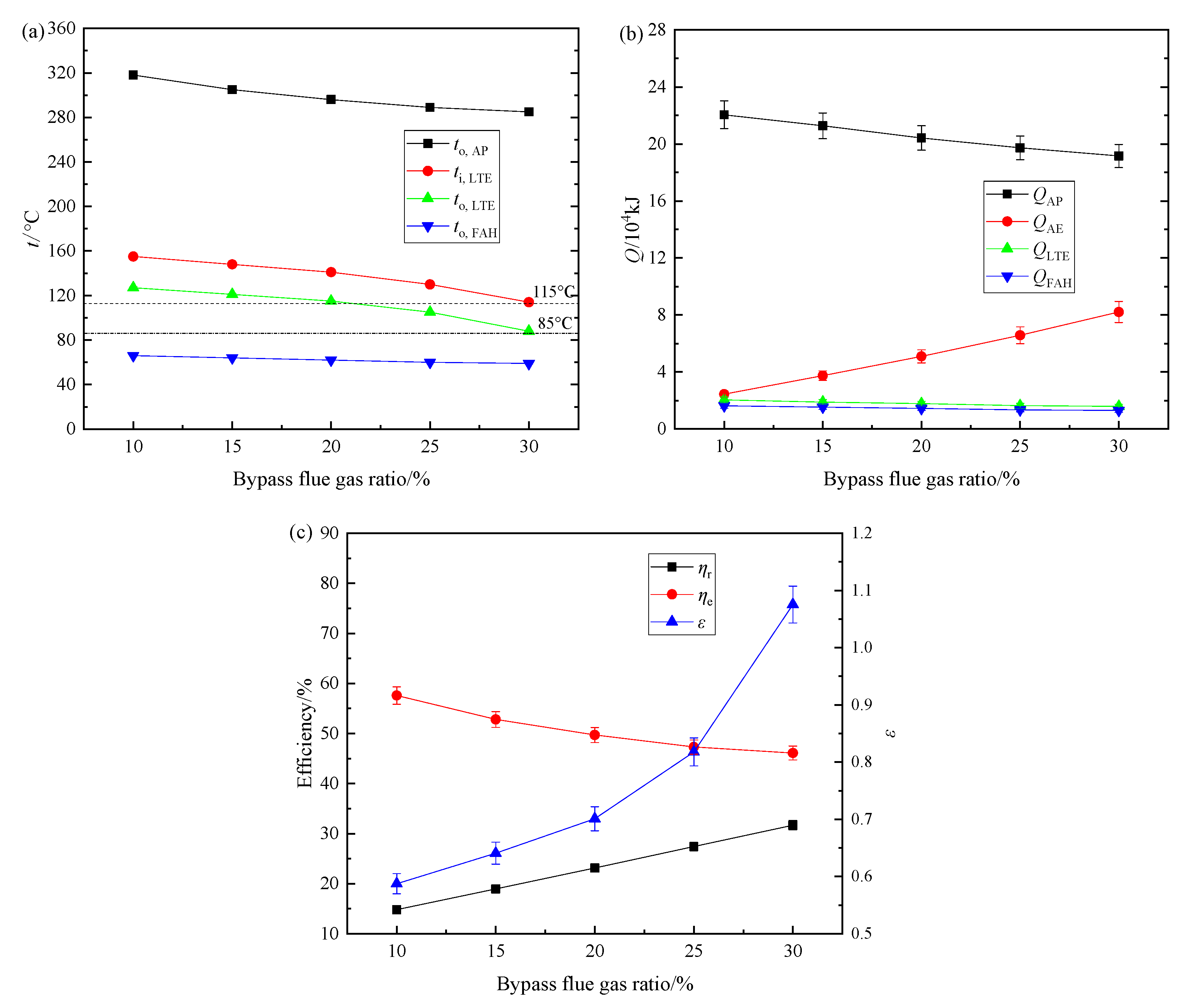
4.3. Effect of Bypass Flue Gas Ratio on Performance Parameters of FWCRS

The flue gas flow was set at 250 Nm3/h, the initial air temperature was 27.1 °C, and the flue gas temperature was 380 °C. As the bypass flue gas ratio varied from 10% to 30% of the total flue gas flow, the relationship between the bypass flue gas ratio and the performance parameters of FWCRS are shown in Figure 7 with error bars.
Figure 7 indicates the main node temperatures decreased as the bypass flue gas ratio increased. When the ratio was about 30%, the exhaust flue gas temperature of LTE was close to the designed value. As the bypass flue gas flow added, more heat was transferred to the circulating water by the HPE and LPE, the bypass flue gas temperature decreased, and at the same time, the flue gas used to heat the air in AP was reduced, the outlet flue gas temperature of AP also decreased. Then the inlet flue gas temperature of LTE was reduced. The heat exchange quantities of AP, LTE, and FAH decreased, and the heat exchange quantity of AE increased. As the flue gas flowed through the AP was reduced, the heat exchange quantity of AP decreased. More flue gas flowed through AE increased heat exchange quantity of AE. The lower node temperature caused the decreased heat exchange quantity in LTE and FAH. As the bypass flue gas ratio added, the inlet flue gas temperature of LTE was greatly reduced, the exergy released by flue gas increased, the reduction of exergy obtained from the air flowing through the AP was dominant, the total exergy decreased, so the system exergy efficiency was reduced. However, more waste heat was recovered in AE, leading to increased waste heat recovery efficiency. The energy grade replacement coefficient increased because the large bypass flue gas ratio reduced the inlet flue gas temperature and exhaust flue gas temperature of LTE, increasing the energy grade of recovered waste heat. It can be seen that changing the bypass flue gas flow can effectively adjust the exhaust temperature and the waste heat recovery efficiency of FWCRS. So the bypass flue gas flow ratio can be used as an important adjustment parameter for FWCRS operation.

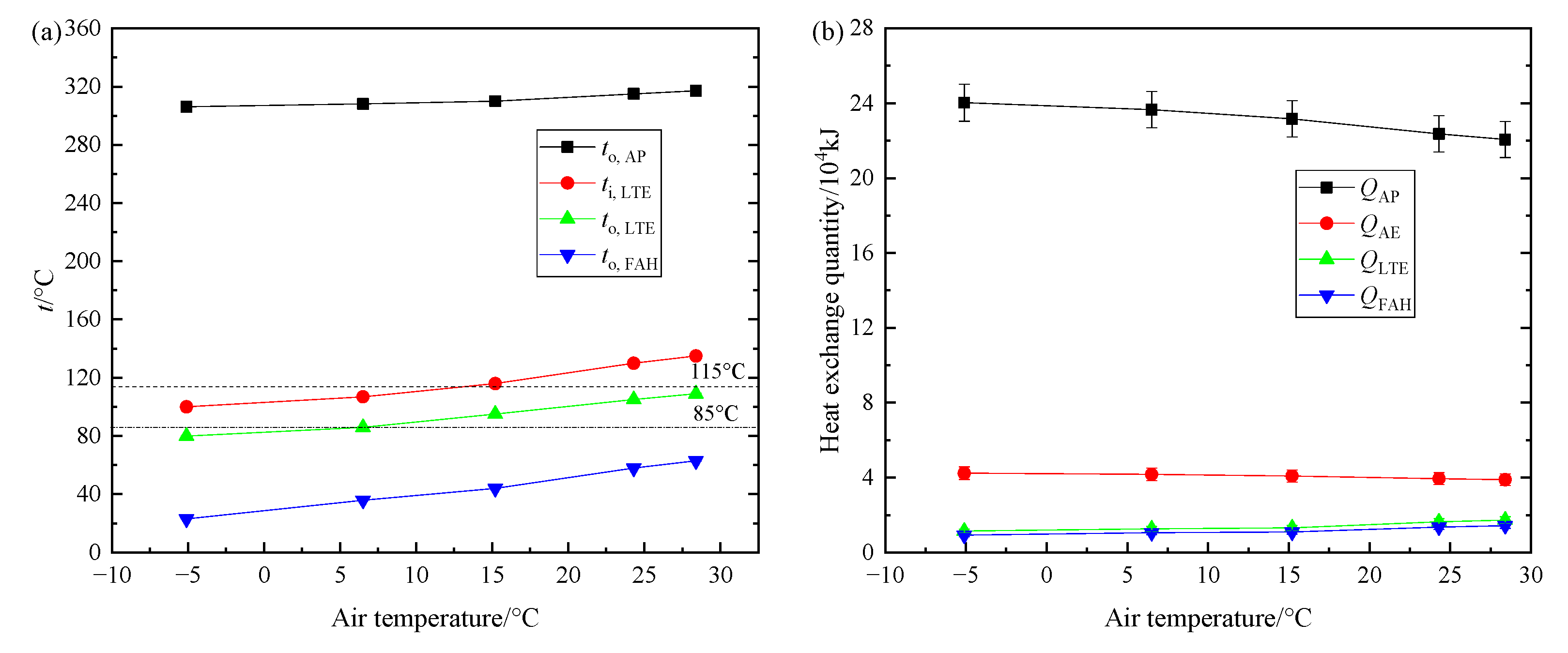
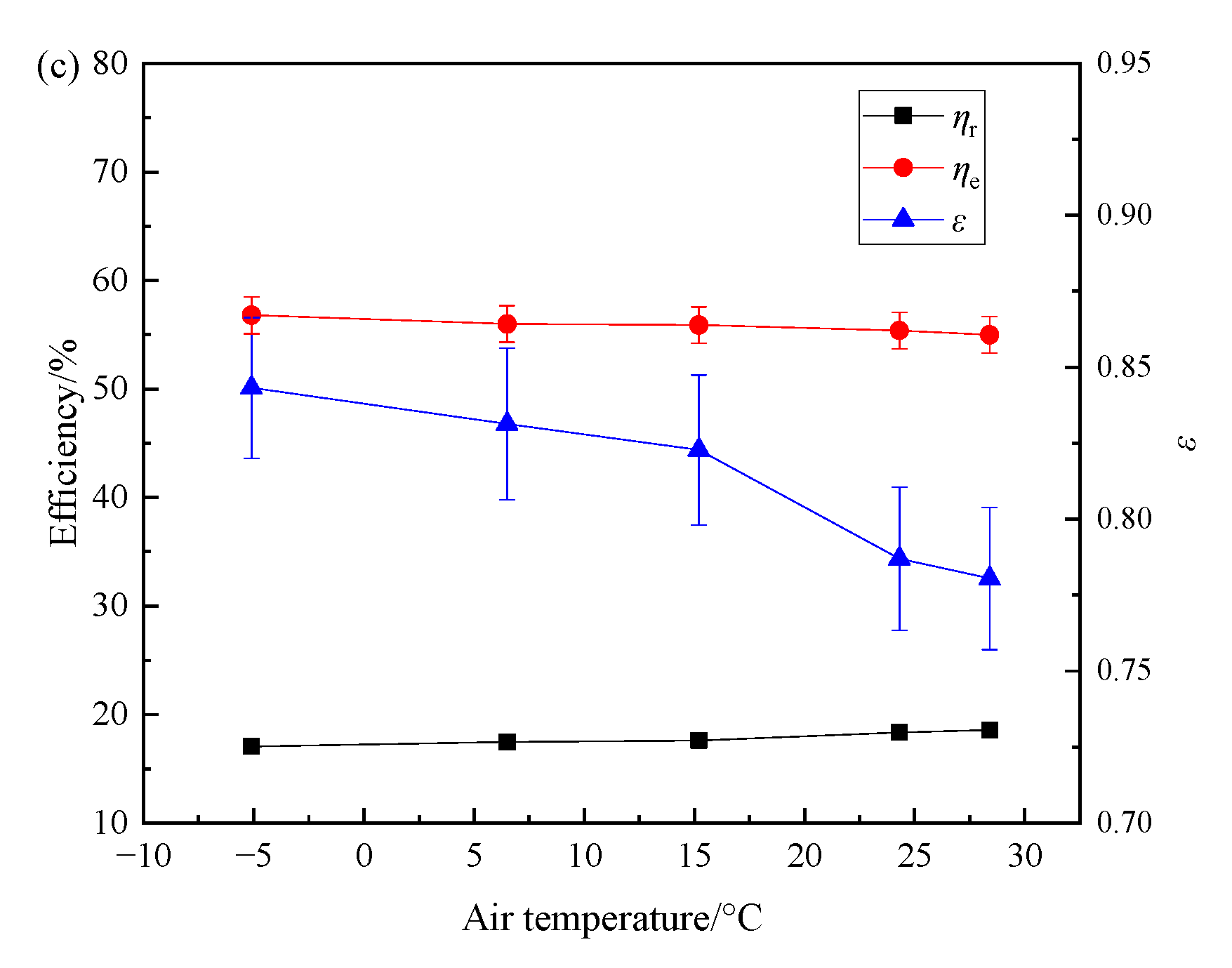
4.4. Effect of Air Temperature on Performance Parameters of FWCRS

The flue gas temperature was set at 380 °C, the flue gas flow was 250 Nm3/h, and the bypass flue gas ratio was about 15% of the total flue gas flow. The experiment was carried out respectively when the air temperature was −5.1 °C, 6.5 °C, 15.2 °C, 24.3° C, and 28.4 °C. The relationship between the air temperature and performance parameters of FWCRS such as main node temperatures, heat exchange quantities of the exchangers, waste heat recovery efficiency, system exergy efficiency, and energy grade replacement coefficient are shown in Figure 8 with error bars.
In Figure 8, as the air temperature increased, the main node temperatures were raised. When the air temperature was −5.1 °C, the exhaust flue gas temperature was about 80 °C, below the designed temperature. The lower air temperature may lead to too low exhaust flue gas temperature and too low inlet air temperature of AP, low−temperature corrosion or ash fouling will occur in the tail flue and cold end of AP, affecting the safe and reliable operation of the unit. Therefore, as the air temperature is low, measures must be taken to control the exhaust flue gas temperature above the safe temperature in the operation of FWCRS. The higher air temperature was not good for reducing exhaust flue gas temperature. The higher air temperature can cause high exhaust flue gas temperature, so the higher air temperature was not good for reducing exhaust flue gas temperature. The heat exchange quantities of LTE and FAH increased slightly and the heat exchange quantities of AE and AP decreased. The main reason was the heat transfer temperature difference of AE and AP was reduced and the temperature difference of LTE and FAH was added because of the increased air temperature. The exergy released from the flue gas was reduced, and the exergy obtained from the air in FAH and AP and the water in AE also decreased, but the obtained exergy reduced more, leading to decreasing system exergy efficiency. The increased air temperature reduced the heat released by the flue gas, the recovered heat in AE and FAH changed slightly, resulting in rising of waste heat recovery efficiency. The increased inlet air temperature and exhaust flue gas temperature of LTE reduced the energy grade replacement coefficient, decreasing the energy grade promotion effect. For FWCRS on an actual unit, the system should be adjusted to make the exhaust flue gas temperature higher than the safe operating temperature of tail heating surface in cold season, and to reduce the exhaust flue gas temperature as much as possible to improve the waste heat use effect in hot season.

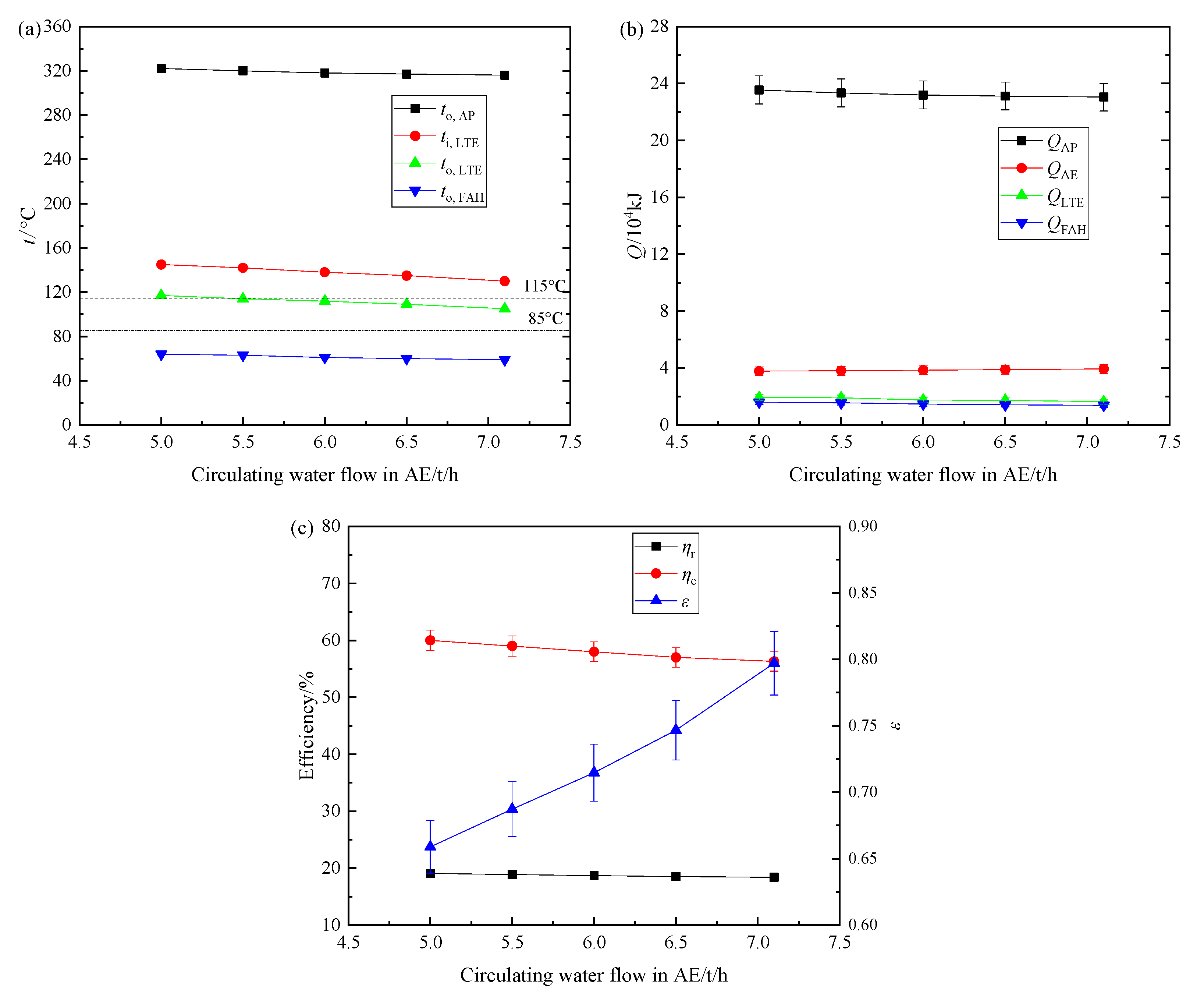
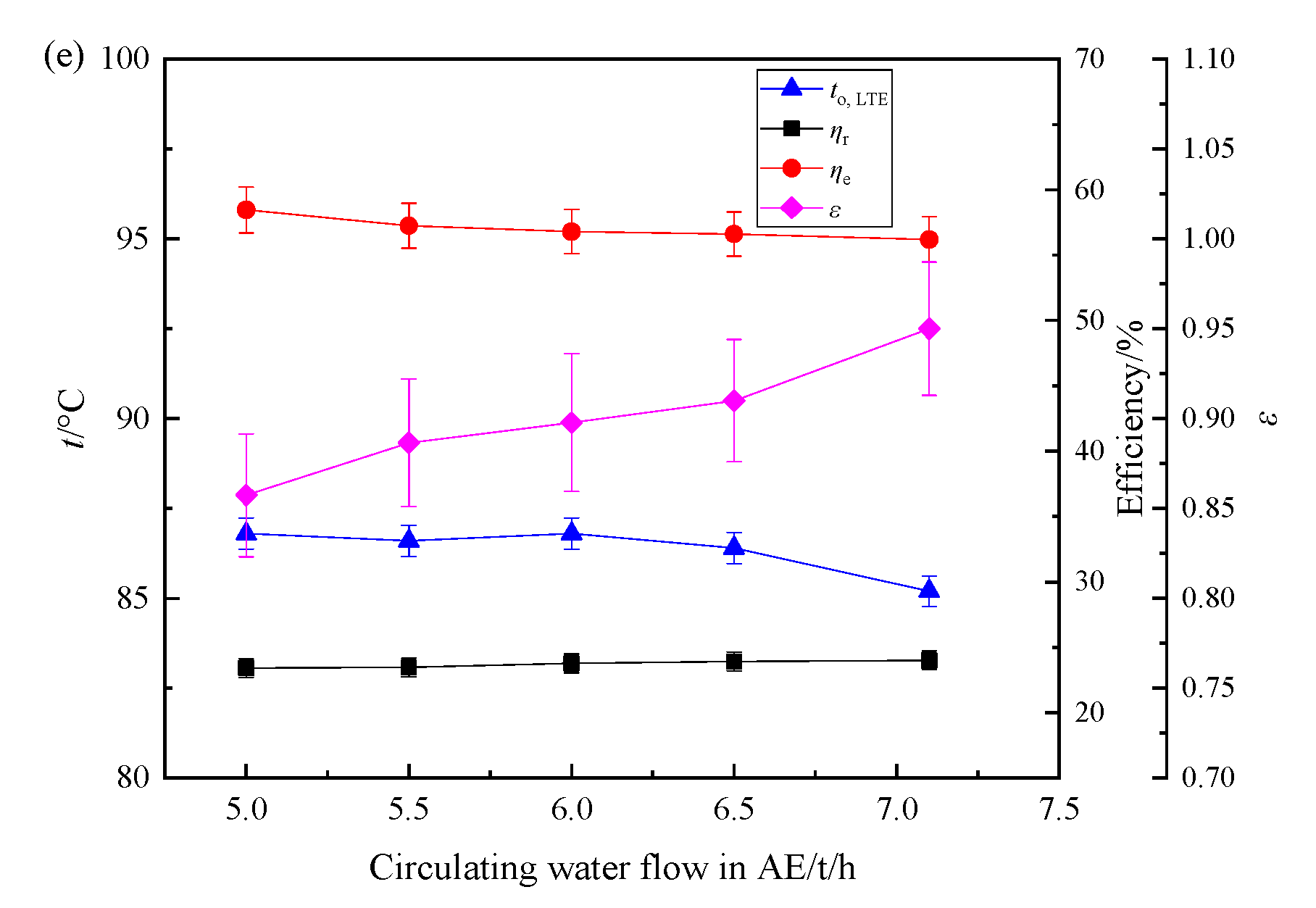
4.5. Effect of Circulating Water Flow in AE on Performance Parameters of FWCRS

The flue gas temperature was set at 380 °C, the flue gas flow was 250 Nm3/h, and the bypass flue gas ratio was about 15% of the total flue gas flow. The circulating water flow in AE was adjusted from 5.0 to 7.1 t/h. The relationship between the circulating water flow in AE and the performance parameters of FWCRS are illustrated in Figure 9 with error bars.
In Figure 9, as the circulating water flow in AE increased, the main node temperatures decreased slightly. The inlet flue gas temperature of LTE and the exhaust flue gas temperature were higher than design value. The node temperatures were not sensitive to circulating flow changes in AE. The heat exchange quantity of AE increased and the heat exchange quantities of AP, LTE and FAH decreased slightly, mainly because the added water flow reduced the inlet flue gas temperature of LTE and decreased the heat exchange quantity. The changes in circulating water flow of AE had a small effect on heat exchange quantities of heat exchangers. The reduced exhaust flue gas temperature increased exergy released from flue gas. However, less exergy obtained in AP and AE increased, leading to decreasing system exergy efficiency. The recovered waste heat in AE increased slightly, and the recovered heat in FAH decreased, the total recovered heat changed a little, but the released heat by flue gas in FWCRS increased more because of the decreased exhaust flue gas temperature, the waste heat recovery efficiency was reduced slightly. The decreased inlet flue gas temperature and exhaust flue gas temperature of LTE promoted the energy grade replacement coefficient, improving the energy grade of waste heat recovered. The changes of circulating water flow in AE have less effect on node temperatures, heat exchange quantities, and waste heat recovery efficiency. The inlet and outlet water temperature of AE are restricted by the water temperature required by other heat exchangers on an actual unit, adjusting the circulating water flow in AE plays a limited role in regulation of FWCRS.

5. Orthogonal Test of Influence Factors

It can be seen from 4.1–4.5, for FWCRS, the main node temperatures, heat exchange quantities in heat exchangers, waste heat recovery efficiency, system exergy efficiency, and energy grade replacement coefficient of the system were affected to different degrees by the operating parameters such as the flue gas flow, flue gas temperature, bypass flue gas ratio, air temperature, and circulating water flow in AE. However, in the actual operation of FWCRS, the operating parameters usually change at the same time. To obtain the variation laws of the main node temperatures, heat exchange quantities in heat exchangers, waste heat recovery efficiency, system exergy efficiency, and energy grade replacement coefficient under variable working conditions by comprehensive experiments, more experiments and more time are required. To determine the main factors affecting the system’s performance, and to guide the operation adjustment of FWCRS, orthogonal test was carried out using exhaust flue gas temperature, waste heat recovery efficiency, system exergy efficiency, and energy grade replacement coefficient of FWCRS as test factors.
In the orthogonal test, five level data of each test factors was selected, and the data is shown in Table 2. The orthogonal table L25 (56) was used in the test. The level data of each test factors was chosen individually based on the orthogonal table for 25 tests, and 25 sets of test results of exhaust flue gas temperature, waste heat recovery efficiency, system exergy efficiency, and energy grade replacement coefficient of FWCRS under different flue gas flow, flue gas temperature, bypass flue gas ratio, air temperature, and circulating water flow in AE were obtained. The influence of the test factors on system performance can be got by range analysis and variance analysis.
Figure 10 indicates the influence of test factors on the performance parameters of FWCRS. It can be seen the variation rules of exhaust flue gas temperature, waste heat recovery efficiency, system exergy efficiency, and energy grade replacement coefficient of FWCRS were basically consistent with the laws in 4.1–4.5. According to the range analysis, the range value and important order of the main factors affected the systems performance parameters were determined and are displayed in Table 3. It can be seen the initial flue gas temperature has the greatest effect on exhaust flue gas temperature to,LTE, the bypass flue gas flow has the most important effect on waste heat recovery efficiency ηr and system exergy efficiency ηe, the air temperature is the most important factor affecting the energy grade replacement coefficient ε. In addition, the flue gas flow is also an important factor affecting performance parameters such as to,LTE and ηe. The circulating water flow in AE has a small impact on the performance parameters of FWCRS. In the actual operation of unit, as the flue gas flow, flue gas temperature, and air temperature are mainly affected by fuel properties, unit loads and ambient environment, they are generally difficult to be adjusted arbitrarily. Therefore, when the unit runs under variable working conditions, adjusting the bypass flue gas ratio is an important way to improve flue gas recovery effect, adjusting circulating water flow in AE can be used as an auxiliary adjustment mean.

6. Conclusions

An experiment bench was designed and built, and using experiments the variation rules of performance parameters of FWCRS such as main node temperatures, heat exchange quantities of AP, AE, LTE, and FAH, as well as waste heat recovery efficiency, system exergy efficiency, and energy grade replacement coefficient of FWCRS were obtained. The orthogonal test was carried out using exhaust flue gas temperature, waste heat recovery efficiency, system exergy efficiency, and energy grade replacement coefficient of FWCRS as test factors, and the main factors affecting the system’s performance were determined. The conclusions are as below.
As the flue gas flow varied from 125 to 250 Nm3/h, the outlet air temperature of FAH and AP, the inlet flue gas temperature of LTE, and the exhaust flue gas temperature increased, the heat exchange quantities of AP, AE, LTE, and FAH also increased, the waste heat recovery efficiency and system exergy efficiency rose slightly, and the energy grade replacement coefficient decreased.
As the flue gas temperature varied from 320 °C to 400 °C, the main node temperature including the outlet air temperature of FAH and AP, inlet flue gas temperature of LTE, and the exhaust flue gas temperature all increased, the heat exchange quantities of exchangers increased, the waste heat recovery efficiency and system exergy efficiency rose slightly, and the energy grade replacement coefficient decreased.
As the bypass flue gas ratio varied from 10% to 30% of the total flue gas flow, the main node temperatures such as the outlet air temperature of FAH and AP, the inlet flue gas temperature of LTE, and the exhaust flue gas temperature decreased, the heat exchange quantities of AP, LTE, and FAH decreased, and the heat exchange quantity of AE increased, the system exergy efficiency was reduced, and the waste heat recovery efficiency and the energy grade replacement coefficient increased.
As the air temperature rose from −5.1 to 28.4 °C, the main node temperatures increased, the heat exchange quantities of LTE and FAH increased slightly and the heat exchange quantities of AE and AP decreased, the waste heat recovery efficiency rose, and the system exergy efficiency and energy grade replacement coefficient decreased.
As the circulating water flow in AE was adjusted from 5.0 to 7.1 t/h, the main node temperatures decreased, the heat exchange quantity of AE increased and the heat exchange quantities of AP, LTE and FAH decreased slightly, the waste heat recovery efficiency rose, and the system exergy efficiency were reduced, and the energy grade replacement coefficient rose.
The orthogonal test proved the variation laws of the exhaust flue gas temperature, waste heat recovery efficiency, system exergy efficiency, and energy grade replacement coefficient of FWCRS were basically consistent with the experiment results. The flue gas temperature, bypass flue gas ratio and air temperature were the significant factors affecting the performance of FWCRS. The bypass flue gas ratio was suggested to be a main adjusting parameter of FWCRS under variable working conditions.

Author Contributions

J.L. designed the experimental bench, carried out the experiments and wrote the manuscript, X.G. and W.Z. processed the experiment data, F.S. provided experimental conditions, reviewed the manuscript and provided valuable suggestions, Q.W. assisted in conducting experiments and made recommendations. All authors have read and agreed to the published version of the manuscript.

Funding

This work was supported by the National Development and Reform Commission Fund of the Power Industry Low–carbon Technology Innovation and Industrialization Demonstration Projects [Development and Reform Office High–tech (2013) 1819] and SDUST Research Fund (2018TDJH101).

Conflicts of Interest

The authors declare no conflict of interest.

Abbreviations

AEAdditional Economizer
ATAir temperature
APAir Preheater
BFRBypass flue gas ratio
CWFCirculating water flow in AE
FAHFront located Air Heater
FGFFlue gas flow
FGTFlue gas temperature
FWCRSFlue gas Waste heat Cascade Recovery system
HPEHigh Pressure Economizer
LPELow Pressure Economizer
LTELow Temperature
Symbols
cAverage specific heat of flue gas, kJ/(kg·K)
cpSpecific heat of flue gas, water, or air, kJ/(kg·K)
EExergy released by flue gas, kJ/kg
EAEExergy obtained by water in AE, kJ
EAPExergy obtained by air in AP, kJ
EfExergy released by flue gas in FWCRS, kJ
GFlow of flue gas, water, or air in unit time, m3/s
QHeat exchange quantity of each heat exchangers, kJ
QAEHeat released by flue gas in AE or heat exchange quantity in AE, kJ
QAPHeat exchange quantity in AP, kJ
QfHeat supplied by flue gas to the system, kJ
QFAHHeat obtained by air from FAH or heat exchange quantity in FAH, kJ
QLTEHeat exchange quantity in LTE, kJ
qHeat released by flue gas, kJ/kg
T1Initial temperature, K
T2Final temperature, K
T0Ambient temperature, K
ti,LTEInlet flue gas temperature of LTE, °C
to,LTEExhaust flue gas temperature of LTE, °C
to,FAHOutlet air temperature of FAH, °C
to,APOutlet air temperature of AP, °C
WElectric power consumption of fans and water pumps in FWCRS in unit time, kJ
xiSingle value of measured x
x ¯ Average value of measured x
x|maxMaximum absolute error of measured x
δxRelative errors of x
εEnergy replacement coefficient
ηeSystem exergy efficiency, %
ηrWaste heat recovery efficiency, %
λEnergy grade of flue gas waste heat
λrEnergy grade of recovered low-grade flue gas waste heat
λsEnergy grade of replaced high-grade flue gas waste heat
ρDensity of flue gas, water, or air, kg/m3
σYUncertainty of Y

References

  1. Chen, H.; Qi, Z.; Dai, L.; Li, B.; Xu, G.; Yang, Y. Performance evaluation of a new conceptual combustion air preheating system in a 1000 MW coal-fueled power plant. Energy 2020, 193, 116739. [Google Scholar] [CrossRef]
  2. Fan, H.; Zhang, Z.; Dong, J.; Xu, W. China’s R & D of advanced ultra-supercritical coal–fired power generation for addressing climate change. Therm. Sci. Eng. Prog. 2018, 5, 364–371. [Google Scholar] [CrossRef]
  3. Xu, G.; Huang, S.; Yang, Y.; Wu, Y.; Zhang, K.; Xu, C. Techno-economic analysis and optimization of the heat recovery of utility boiler flue gas. Appl. Energy 2013, 112, 907–917. [Google Scholar] [CrossRef]
  4. Jin, Y.; Gao, N.; Zhu, T. Techno-economic analysis on a new conceptual design of waste heat recovery for boiler exhaust flue gas of coal-fired power plants. Energy Convers. Manag. 2019, 200, 112097. [Google Scholar] [CrossRef]
  5. Stevanovic, V.D.; Wala, T.; Muszynski, S.; Muszynski, S.; Milic, M.; Jovanovic, M. Efficiency and power upgrade by an additional high pressure economizer installation at an aged 620MWe lignite-fired power plant. Energy 2014, 66, 907–918. [Google Scholar] [CrossRef]
  6. Espatolero, S.; Cortés, C.; Romeo, L. Optimization of boiler cold-end and integration with the steam cycle in supercritical units. Appl. Energy 2010, 87, 1651–1660. [Google Scholar] [CrossRef]
  7. Ma, Y.; Yang, L.; Lu, J.; Pei, Y. Techno-economic comparison of boiler cold-end exhaust gas heat recovery processes for efficient brown-coal-fired power generation. Energy 2016, 116, 812–823. [Google Scholar] [CrossRef]
  8. Wang, C.; He, B.; Yan, L.; Pei, X.; Chen, S. Thermodynamic analysis of a low-pressure economizer based waste heat recovery system for a coal-fired power plan. Energy 2014, 65, 80–90. [Google Scholar] [CrossRef]
  9. Liu, M.; Yan, J.; Chong, D.; Liu, J.; Wang, J. Thermodynamic analysis of pre-drying methods for pre–dried lignite–fired power plant. Energy 2013, 49, 107–118. [Google Scholar] [CrossRef]
  10. Han, X.; Liu, M.; Zhai, M.; Chong, D.; Yan, J.; Xiao, F. Investigation on the off-design performances of flue gas pre-dried lignite-fired power system integrated with waste heat recovery at variable external working conditions. Energy 2015, 90, 1743–1758. [Google Scholar] [CrossRef]
  11. Jiménez–Arreola, M.; Pili, R.; Magro, F.; Wieland, C.; Rajoo, S.; Romagnoli, A. Thermal power fluctuations in waste heat to power systems: An overview on the challenges and current solutions. Appl. Therm. Eng. 2018, 134, 576–584. [Google Scholar] [CrossRef]
  12. Mikielewicz, D.; Wajs, J.; Ziółkowski, P.; Mikielewicz, J. Utilisation of waste heat from the power plant by use of the ORC aided with bleed steam and extra source of heat. Energy 2016, 97, 11–19. [Google Scholar] [CrossRef]
  13. Goodarzi, S.; Javaran, E.; Rahnama, M.; Ahmadi, M. Techno-economic evaluation of a multi effect distillation system driven by low–temperature waste heat from exhaust flue gases. Desalination 2019, 460, 64–80. [Google Scholar] [CrossRef]
  14. Li, C.; Wang, H. Power cycles for waste heat recovery from medium to high temperature flue gas sources—From a view of thermodynamic optimization. Appl. Energy 2016, 180, 707–721. [Google Scholar] [CrossRef]
  15. Wei, M.; Zhao, X.; Fu, L.; Zhang, S. Performance study and application of new coal–fired boiler flue gas heat. Appl. Energy 2017, 188, 121–129. [Google Scholar] [CrossRef]
  16. Wang, C.; He, B.; Sun, S.; Wu, Y.; Yan, N.; Yan, L.; Pei, X. Application of a low pressure economizer for waste heat recovery from the exhaust flue gas in a 600 MW power plant. Energy 2012, 48, 196–202. [Google Scholar] [CrossRef]
  17. Xu, G.; Xu, C.; Yang, Y.; Fang, Y.; Li, Y.; Song, X. A novel flue gas waste heat recovery system for coal-fired ultra-supercritical power plants. Appl. Therm. Eng. 2014, 67, 240–249. [Google Scholar] [CrossRef]
  18. Stevanovic, V.; Petrovic, M.; Wala, T.; Milivojevic, S.; Ilic, M.; Muszynski, S. Efficiency and power upgrade at the aged lignite-fired power plant by flue gas waste heat utilization: High pressure versus low pressure economizer installation. Energy 2019, 187, 115980. [Google Scholar] [CrossRef]
  19. Han, Y.; Xu, G.; Zheng, Q.; Xu, C.; Hu, Y.; Yang, Y.; Lei, J. New heat integration system with bypass flue based on the rational utilization of low-rade extraction steam in a coal–fired power plant. Appl. Therm. Eng. 2017, 113, 460–471. [Google Scholar] [CrossRef]
  20. Yan, M.; Zhang, L.; Shi, Y.; Zhang, L.; Li, Y.; Ma, C. A novel boiler cold-end optimisation system based on bypass flue in coal-fired power plants: Heat recovery from wet flue gas. Energy 2018, 152, 84–94. [Google Scholar] [CrossRef]
  21. Fan, C.; Pei, D.; Wei, H. A novel cascade energy utilization to improve efficiency of double reheat cycle. Energy Convers. Manag. 2018, 171, 1388–1396. [Google Scholar] [CrossRef]
  22. Yang, Y.; Xu, C.; Xu, G.; Han, Y.; Fang, Y.; Zhang, D. A new conceptual cold-end design of boilers for coalfired power plants with waste heat recovery. Energy Convers. Manag. 2015, 89, 137–146. [Google Scholar] [CrossRef]
  23. Song, J.; Li, Y.; Xu, Q.; Han, Y.; Xu, G. Analysis and optimization of the low temperature economizer under off-design operating conditions. Power Syst. Eng. 2015, 31, 17–20. (In Chinese) [Google Scholar]
  24. Song, J.; Li, Y.; Li, F.; Han, Y.; Xu, G. Energy–saving effect variable condition analysis of depth waste heat utilization system under off–design condition in utility boiler. Boiler Technol. 2015, 46, 6–12. (In Chinese) [Google Scholar]
  25. Zhang, G.; Liu, M.; Zhang, J.; Yang, L.; Liu, J. Performance Analyses of a 600MW Coal–Fired Power Plant Integrated with a Novel Boiler Exhaust Heat Recovery System at Overall Working Conditions. Chin. Soc. Elec. Eng. 2018, 38, 3588–3596. [Google Scholar]
  26. Han, X.; Liu, M.; Wang, J.; Yan, J.; Liu, J.; Xiao, F. Simulation study on lignite-fired power system integrated with flue gas drying and waste heat recovery—Performances under variable power loads coupled with off-design parameters. Energy 2014, 76, 406–418. [Google Scholar] [CrossRef]
  27. Starkloff, R.; Alobaid, F.; Karner, K.; Epple, B.; Schmitz, M.; Boehm, F. Development and validation of a dynamic simulation model for a large coal-fired power plant. Appl. Therm. Eng. 2015, 91, 496–506. [Google Scholar] [CrossRef]
  28. Alobaid, F.; Mertens, N.; Starkloff, R.; Lanz, T.; Heinze, C.; Epple, B. Progress in dynamic simulation of thermal power plants. Prog. Energy Combust. Sci. 2016, 59, 79–162. [Google Scholar] [CrossRef]
  29. Chen, H.; Pan, P.; Shao, H.; Wang, Y.; Zhao, Q. Corrosion and viscous ash deposition of a rotary air preheater in a coal-fired power plant. Appl. Therm. Eng. 2017, 113, 373–385. [Google Scholar] [CrossRef]
  30. Chen, H.; Pan, P.; Wang, Y.; Zhao, Q. Field study on the corrosion and ash deposition of low–temperature heating surface in a large-scale coal-fired power plant. Fuel 2017, 208, 149–159. [Google Scholar] [CrossRef]
  31. Li, Z.; Sun, F.; Shi, Y.; Li, F.; Ma, L. Experimental Study and Mechanism Analysis on Low Temperature Corrosion of Coal Fired Boiler Heating Surface. Appl. Therm. Eng. 2016, 80, 355–361. [Google Scholar] [CrossRef]
  32. Wei, W.; Sun, F.; Ma, L. Effect of fine ash particles on formation mechanism of fouling covering heat exchangers in coal-fired power plants. Appl. Therm. Eng. 2018, 142, 269–277. [Google Scholar] [CrossRef]
  33. Wei, W.; Sun, F.; Shi, Y.; Ma, L. Theoretical prediction of acid dew point and safe operating temperature of heat exchangers for coal-fired power plants. Appl. Therm. Eng. 2017, 123, 782–790. [Google Scholar] [CrossRef]
  34. Liu, J.; Sun, F.; Ma, L.; Wei, W. Coupled high-low energy level flue gas heat recovery system and its application in 1000 MW ultra-supercritical double reheat coal-fired unit. In Proceedings of the ASME 2017 Power Conference Joint with ICOPE–17, Charlotte, NC, USA, 26–30 June 2017. [Google Scholar]
  35. Liu, J.; Sun, F. Experimental study on operation regulation of a coupled high–low energy flue gas waste heat recovery system based on exhaust gas temperature control. Energies 2019, 12, 706. [Google Scholar] [CrossRef] [Green Version]
  36. Liu, J.; Sun, F. Node temperature of the coupled high-low energy grade flus gas waste feat recovery system. Energies 2019, 12, 248. [Google Scholar] [CrossRef] [Green Version]
Figure 1. Technical process of flue gas waste heat cascade recovery system. AP: Air Preheater; AE: Additional Economizer; LTE: Low Temperature Economizer; FAH: Front-located Air Heater.
Energies 13 00324 g001
Figure 2. Technical process of FWCRS on a 1000 MW ultra-supercritical double reheat coal-fired unit. AP: Air Preheater; HPE: High Pressure Economizer; LPE: Low Pressure Economizer; LTE: Low Temperature Economizer; FAH: Front-located Air Heater.
Energies 13 00324 g002
Figure 3. Flow chart of flue gas waste heat cascade recovery experimental bench. AP: Air Preheater; FAH: Front-located Air Heater; HPE: High Pressure Economizer; LPE: Low Pressure Economizer; LTE: Low Temperature Economizer.
Energies 13 00324 g003
Figure 4. Experimental setup of flue gas waste heat cascade recovery system. AP: Air Preheater; FAH: Front-located Air Heater; HPE: High Pressure Economizer; LPE: Low Pressure Economizer; LTE: Low Temperature Economizer.
Energies 13 00324 g004
Figure 5. Effect of flue gas flow on FWCRS: (a) Relationship between flue gas flow and main node temperatures; (b) Relationship between flue gas flow and heat exchange quantities of heat exchangers; (c) Relationship between flue gas flow and ηr, ηe, and ε.
Energies 13 00324 g005
Figure 6. Effect of flue gas temperature on FWCRS: (a) Relationship between flue gas temperature and main node temperatures; (b) Relationship between flue gas flow and heat exchange quantities of heat exchangers; (c) Relationship between flue gas temperature and ηr, ηe, and ε.
Energies 13 00324 g006
Figure 7. Effect of bypass flue gas ratio on FWCRS: (a) Relationship between bypass flue gas ratio and main node temperatures; (b) Relationship between bypass flue gas ratio and heat exchange quantities of heat exchangers; (c) Relationship between bypass flue gas ratio and ηr, ηe, and ε.
Energies 13 00324 g007
Figure 8. Effect of air temperature on FWCRS: (a) Relationship between air temperature and main node temperatures; (b) Relationship between air temperature and heat exchange quantities of heat exchangers; (c) Relationship between air temperature and ηr, ηe, and ε.
Energies 13 00324 g008aEnergies 13 00324 g008b
Figure 9. Effect of circulating water flow in AE on FWCRS: (a) Relationship between circulating water flow in AE and main node temperatures; (b) Relationship between circulating water flow in AE and heat exchange quantities of heat exchangers; (c) Relationship between circulating water flow in AE and ηr, ηe, and ε.
Energies 13 00324 g009
Figure 10. Orthogonal analysis of the factors affected exhaust flue gas temperature, waste heat recovery efficiency, system exergy efficiency, and energy grade replacement coefficient: (a) Flue gas flow; (b) Flue gas temperature; (c) Bypass flue gas ratio; (d) Air temperature; (e) Circulating water flow in AE.
Energies 13 00324 g010aEnergies 13 00324 g010b
Table 1. Measuring instruments used in the experiments.
Measuring InstrumentsManufacturerModelAccuracy
Thermal resistanceHong De Control Technology (Shanghai) Co., Ltd., Shanghai, ChinaHD-WZPK-2380.1 °C
Gas flow meterXi’an Zhongwang Measurement and Control Instrument Co., Ltd., Xi’an, ChinaFCY-110D-AMYG±1%
Water flow meterHebei Feigerise Automation Technology Co., Ltd., Langfang, ChinaPMFG-S-32-FAPAC0116EIASAR0.5
Smart pressure transmitterHong De Control Technology (Shanghai) Co., Ltd., Shanghai, ChinaHD3051GP3S22M3B3C10.1
Table 2. Level data of test factors in orthogonal test.
Level DataTest Factors
Flue Gas Flow/Nm3/hFlue Gas Temperature/℃Bypass Flue Gas Ratio /%Air Temperature/℃Circulating Water Flow in AE/t/h
112532010−5.15
2156340156.55.5
31883602015.26
42193802524.36.5
52504003028.47.1
Table 3. Importance order of the influencing factors.
Test FactorsRange ValueImportance Order
FGF 1FGT 2AT 3BFR 4CWF 5
to,LTE8.431.42.06.22.2FGT > FGF > BFR > CWF > AT
ηr0.00830.01620.00410.17990.0046BFR > FGT > FGF > CWF > AT
ηe0.03020.01020.02030.13160.0186BFR > FGF > AT > CWF > FGT
ε0.08390.42040.46450.17380.1058AT > FGT > BFR > CWF > FGF
Notes: 1 FGF: Flue gas flow; 2 FGT: Flue gas temperature; 3 AT: Air temperature; 4 BFR: Bypass flue gas ratio; 5 CWF: Circulating water flow in AE.

