Article

Expansion of Operating Speed Range of High-Speed BLDC Motor Using Hybrid PWM Switching Method Considering Dead Time

1
Future Transport Machinery Technology Department, Busan Technopark, Busan 46742, Korea
2
Department of Electrical Engineering, Pusan National University, Busan 46241, Korea
*
Author to whom correspondence should be addressed.
Energies 2020, 13(19), 5212; https://doi.org/10.3390/en13195212
Submission received: 31 August 2020 / Revised: 30 September 2020 / Accepted: 1 October 2020 / Published: 6 October 2020
(This article belongs to the Special Issue Control of Power Electronics Converters and Electric Motor Drives)

Abstract

:
In vehicle electrical systems with limited battery power, the output torque and speed of high-speed brushless DC (BLDC) motors can decrease due to unstable and reduced supply voltage or manufacturing errors in the motor back electromotive force (EMF). This paper presents a method that can guarantee the output performance of an inverter through a control algorithm without a separate power supply system and DC-link voltage increase. The proposed control algorithm can increase the output torque and speed of a high-speed BLDC motor by using appropriate selection and change of the inverter’s pulse width modulation (PWM) control method. In this paper, the operation and electrical characteristics of various PWM methods of BLDC motors are analyzed, and the optimal PWM method for improving the control performance of high-speed BLDC motors is presented. In addition, the relationship between the switching frequency, dead time, and voltage utilization was mathematically analyzed. Based on the results of this analysis, the proposed control algorithm automatically changes the PWM switching mode at the point where the output torque and speed need to be extended. The effectiveness and feasibility of the control method proposed in this paper is verified through the experimental results on the designed and manufactured high-speed BLDC motor system for vehicles.

1. Introduction

Recently, the importance and proportion of electrical and motor drive systems have been on the rise in automobile systems that require advanced technology [1,2,3,4]. In particular, the use of high-speed motors, such as electric compressors and superchargers in the intake and exhaust systems of engines, is increasing [3,4]. Permanent magnet brushless DC (BLDC) motors are used mainly as high-speed motors for several industrial applications because they offer numerous advantages in terms of high efficiency and power density, power factor and torque characteristics, compactness, and weight [5,6,7].
A stable power supply environment of the vehicle system is important for the control of power electronics converters and electric motor drives inside the vehicle. However, it is possible that the voltages of the vehicle battery and the power storage system decrease due to changes in the temperature and electrical load, without keeping the voltage value constant [8,9]. In addition, high-speed motors are designed and manufactured to have a very low inductance and back electromotive force (EMF) for operation at a target speed in a limited voltage environment, but an error may occur in the back-EMF value in the manufacturing process [10,11,12,13].
These two practical problems adversely affect the performance of inverter and motor drive systems. The torque and speed of the motor may output as much as the difference between the supply voltage of the inverter and the back-EMF voltage [14]. However, if the supply voltage of the inverter is decreased or the back-EMF value of the motor windings is increased, the output torque and speed of the motor cannot reach the target value. Achieving the target torque and speed output of the motor is essential to satisfying vehicle performance.
To solve these practical problems, the solution in the existing literature is to additionally build a power storage system or a step-up converter for stable power supply to the inverter. The additional power storage system can serve as an auxiliary battery by using a super- or ultra-capacitor, so that stable power supply of the inverter is possible [15,16]. Moreover, the step-up converter can supply a high and stable voltage by adding a DC/DC boost converter to the front of the inverter [17,18,19]. Accordingly, the motor output torque and speed can be increased even under increased back-EMF conditions. However, the additional configuration of these auxiliary systems increases the cost and size and requires a separate control, management, balancing, and monitoring system [20,21,22].
Therefore, the stability of the output performance of the high-speed BLDC motor and inverter system should be guaranteed independently of the construction of such an additional power supply system. In this paper, without the additional power supply system and an increase in the DC-link voltage, a method for increasing the motor output torque and speed through the inverter control algorithm is presented. Under the same operating conditions of the inverter, the proposed control algorithm can increase the output torque and speed of a high-speed BLDC motor by using appropriate selection and change of the inverter’s pulse width modulation (PWM) control method. Section 2.1 introduces the basic configuration and operating method of a three-phase BLDC motor inverter system. In Section 2.2 and Section 2.3, various PWM methods of BLDC motors are analyzed, and a PWM method suitable for the operation of high-speed BLDC motors is presented. In Section 2.4, the effect of the dead time on the motor output performance of the complementary/non-complementary switching mode of the optimal PWM method presented in Section 2.3 is analyzed. Section 3 describes the proposed overall control algorithm. In Section 4, the effectiveness of the proposed control algorithm is verified through experimental results obtained from the high-speed BLDC motor drive system designed and manufactured for a vehicle compressor. Finally, conclusions are presented in Section 5.

2. Three-Phase BLDC Motor Inverter System and PWM Methods

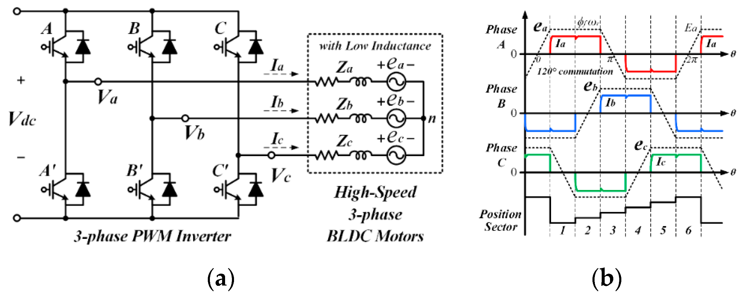
2.1. Three-Phase BLDC Motor Inverter System

Figure 1a presents the equivalent circuit of the three-phase BLDC motor inverter system. The BLDC motor is driven and controlled by an inverter, and energy is transferred from the DC power supply to the BLDC motor through the sequential commutation and conduction operation of the three-phase inverter. As shown in Figure 1b, a three-phase BLDC motor with a trapezoidal back-EMF waveform is driven by two-phase excitation method, which involves the principle of injecting positive and negative rectangular phase currents during 120° periods while the back-EMF is flat as per the rotor position. Accordingly, it becomes possible to keep the torque output of the BLDC motor constant, and the remaining one phase for which the back-EMF is not flat does not become excited. Here, the position information of the rotor (i.e., back-EMF) is essential: the rotor position is divided into six position sectors with 60° intervals using the hall effect sensors. Then, the phase windings of the stator are sequentially excited according to the position sectors. The magnitude of the injected current for each phase can be controlled by the PWM’s ON/OFF operation [23,24,25,26].
In the motor drive system, the direction of energy transfer depends on the operating mode. The operation mode is divided into four quadrants according to the motor rotation and torque direction. In the BLDC motor drive system, the possibility of four-quadrant operation is determined by the PWM method. Under the PWM method, which cannot generate a reverse voltage in the direction opposite to the phase back-EMF of the motor, the BLDC motor cannot operate in four quadrants without an additional control approach [27,28].

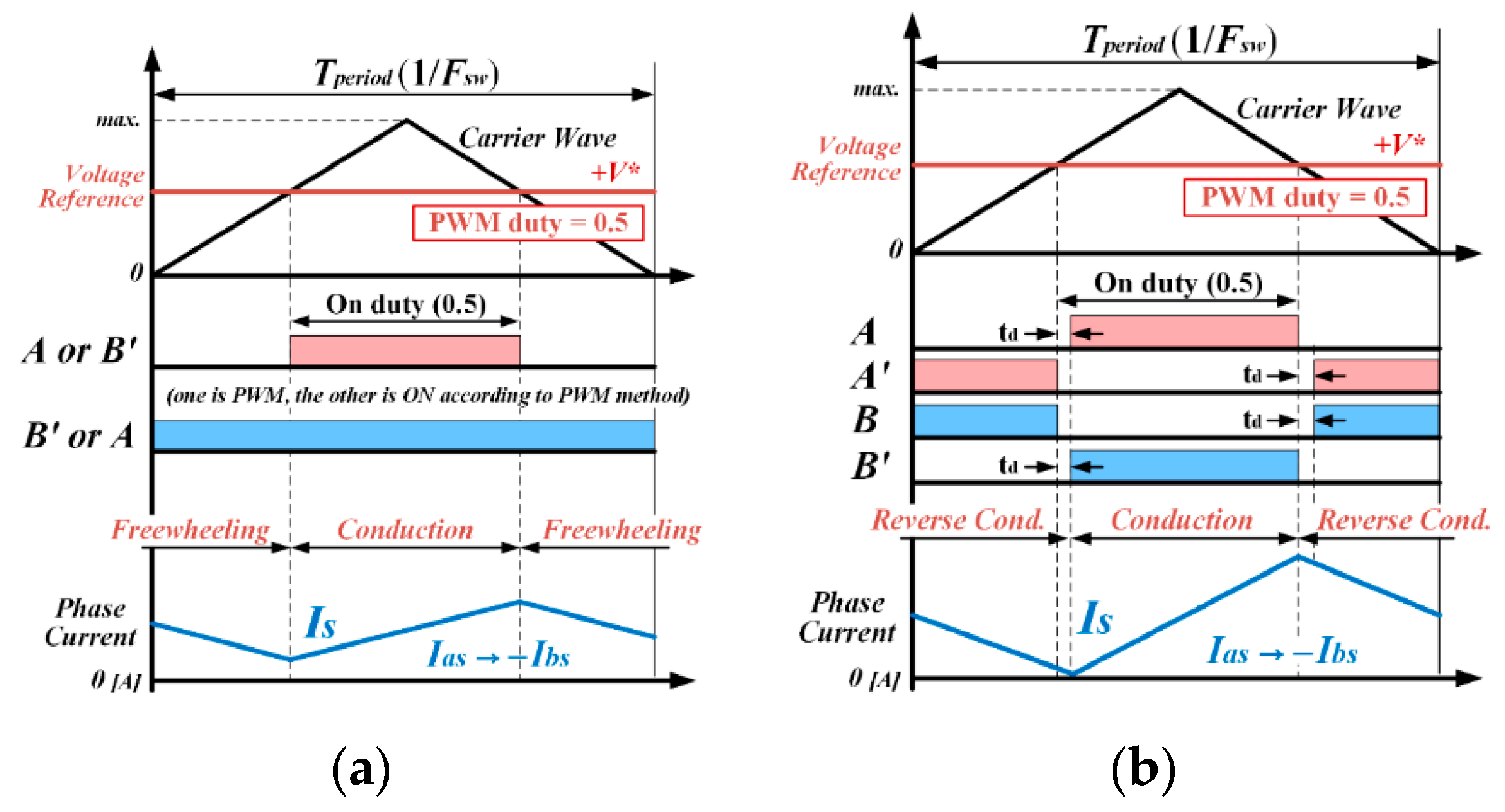
2.2. Unipolar and Bipolar PWM Methods

The output performance and electrical characteristics of a BLDC motor system can be determined based on the PWM control method used. Among the six switching devices of an inverter, the PWM ON/OFF patterns for each position sector vary according to the PWM technique employed. The various PWM methods for a BLDC motor can be classified into unipolar and bipolar PWM methods depending on their output voltage type. Figure 2 shows an example of a PWM pattern formed by using unipolar and bipolar PWM methods in one switching cycle of Position Sector 1 [23,24,25].
The unipolar PWM method in Figure 2a uses two switching devices on two excited phases. One switching device operates in the PWM mode, while the other switching device operates in the ON mode depending on the position sector. Accordingly, the unipolar PWM method outputs forward voltage and 0 during conduction and freewheeling operations, respectively, by activating the PWM ON and OFF cycles. Here, the operating mode and sequence of the two switching devices operating in PWM or ON modes are different depending on the PWM method used [29,30]. Compared to the bipolar method, this unipolar PWM method provides the advantage of reducing the amplitude of the current ripples by half, as the output voltage fluctuation between PWM ON and OFF is half of that in the bipolar method. However, the low voltage fluctuation that occurs with the unipolar method degrades the control responsiveness, and the four-quadrant operation and regenerative braking are impossible because the inverter cannot output the reverse voltage without using the additional control approach [31,32].
On the other hand, the bipolar PWM method of Figure 2b uses both the upper and lower four switches in the two excited phases, and the PWM operation of the upper and lower switches of each phase is complementary. Accordingly, the inverter outputs the forward voltage and reverse voltage alternately through the conduction and reverse conduction operations, respectively, without the freewheeling operation. This bipolar output type PWM method has the opposite advantages and disadvantages to those of the unipolar PWM method. Since reverse voltage output is possible, the control response is fast, and four-quadrant operation and regenerative braking are possible. However, since the voltage fluctuation between PWM ON and OFF is doubled, the amplitude of the current ripples, heat, and electrical loss also increase [24,32].

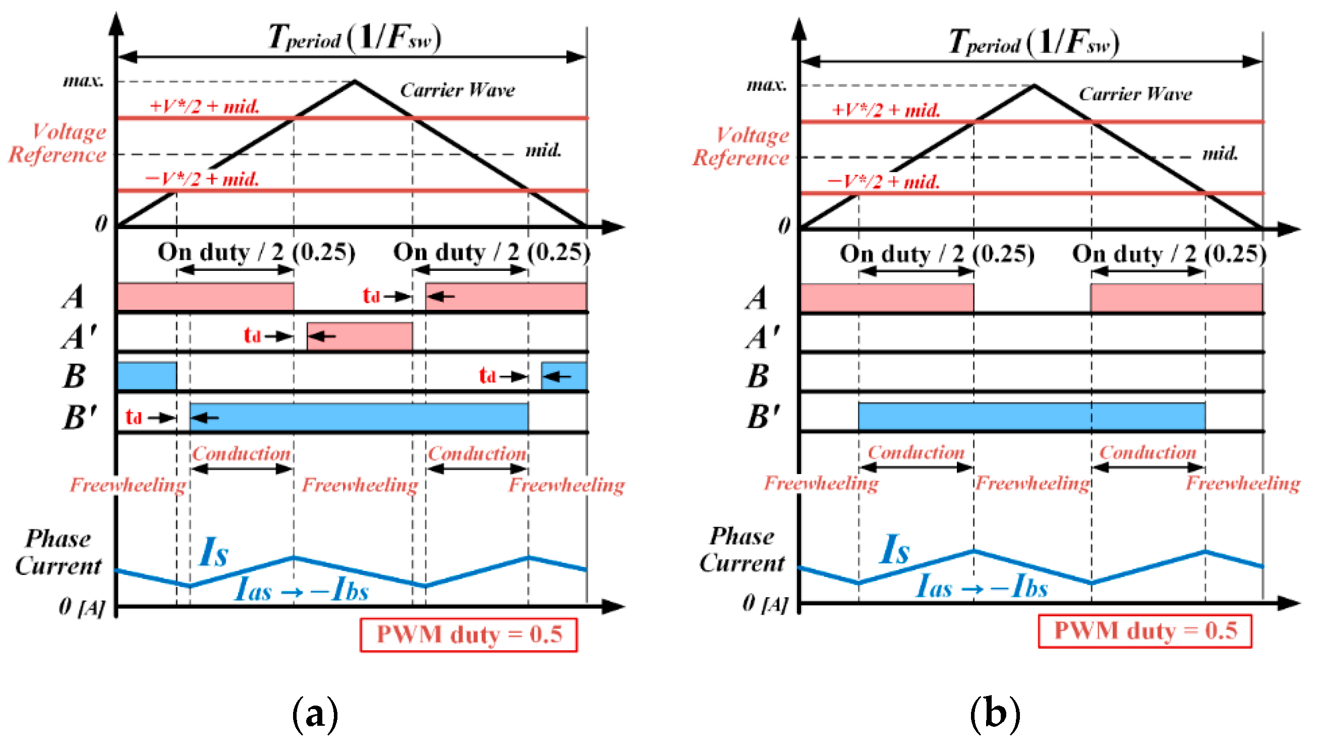
2.3. H-PWM-L-PWM Method for High-Speed BLDC Motors

In order to overcome the shortcomings of the unipolar and bipolar PWM methods, the H-PWM-L-PWM method (called the modified bipolar or double unipolar PWM method), a PWM method that appropriately combines the two PWM methods, is used. As shown in Figure 3, this method operates two switching devices in the two excited phases using an interleaved PWM pattern with a phase-angle difference of half the switching cycle. Accordingly, the conduction and freewheeling operations are divided into two time intervals, each within one switching cycle, and the ON and OFF times are also divided in half and each occurs twice. In this method, the voltage fluctuation between PWM ON and OFF is the same as in the unipolar PWM method. However, due to the conduction time being half, the current ripple is reduced by half. Theoretically, the reduction ratio is 1/2 and 1/4 compared to the unipolar and bipolar PWM methods, respectively [33,34].
In a high-speed BLDC motor in an environment of limited power supply, such as a vehicle in which the inductance and resistance of the phase windings are very small, very large current ripples occur compared to those produced in general BLDC motors. Such a current ripple not only causes noise, mechanical vibration, and heat generation along with torque pulsation but also causes instability of the control system due to difficulties in measuring current and the generation of electromagnetic noise. Thus, reducing of current ripples in high-speed BLDC motor drive systems is a crucial control goal. Therefore, in high-speed BLDC motor inverter systems that require improved control responsiveness and reduced current ripple, the H-PWM-L-PWM method is the most suitable PWM method for reducing the current ripples while enabling four-quadrant operation [33,34,35].
The H-PWM-L-PWM method can be used in two modes based on the complementary or non-complementary switching operation of the upper and lower switching devices of the two excitation phases, as illustrated in Figure 3. The complementary switching mode in Figure 3a enables bipolar voltage output by operating four switches complementarily, while the non-complementary switching mode in Figure 3b outputs only unipolar voltage by operating only two switches non-complementarily. Since the complementary switching mode is capable of providing bipolar voltage output, it can be used for the four-quadrant operation and regenerative braking, but the maximum voltage utilization rate is reduced because the dead time is applied twice per switching cycle. The voltage utilization rate is the ratio of the actual output voltage to the input power supply of the inverter. On the other hand, in the non-complementary switching mode, the four-quadrant operation and regenerative braking are not possible as they were in the unipolar PWM method, but the maximum voltage utilization rate can be increased because the dead time is not used. Table 1 presents the electrical characteristics, advantages, and disadvantages of the unipolar, bipolar, and H-PWM-L-PWM methods.

2.4. Relationship between Dead Time and Voltage Utilization Rate

For the four-quadrant operation of BLDC motors, a complementary PWM switching operation is required between the upper and lower switching devices on each arm of the inverter, and a dead time to avoid the arm-short circuit must be applied to the complementary PWM switching pattern [36,37]. The dead time is a constant value that is determined by the electrical characteristics of the power switching device, such as turn-on/off delay time. It is set in a range in which the upper and lower switches do not turn on simultaneously and is applied to the complementary PWM pattern with a constant length in every switching cycle. In commercial switching devices, such as silicon IGBT or MOSFET, a dead time of about 1~3 μs is generally required [37].
However, no output voltage can be produced during the dead time within one switching cycle, and the maximum voltage utilization (output) rate of the inverter is reduced by the respective dead time. Accordingly, the maximum output torque and speed of the high-speed BLDC motor are also reduced. In addition, high-speed BLDC motors are generally operated with high-frequency switching to ensure control precision at high operating speeds [11]. However, under an operating condition with a high switching frequency, the actual conduction time decreases under the same PWM ratio because the dead time is always applied with a constant length, even when the switching period decreases. This means that, as the switching frequency increases, the proportion of dead time within one switching period increases and the output torque and speed decrease due to the reduced output voltage.
Equation (1) gives the calculated voltage utilization rate Rate-VU using the PWM duty ratio, dead time, and switching frequency in the H-PWM-L-PWM method. This rate is the ratio of the actual voltage output (conduction) time, excluding the dead time, to the switching period according to the switching frequency. Here, D is the PWM duty ratio, fsw is the switching frequency, and Td is the dead time. The equation for the maximum output voltage utilization rate Rate-Max.VU is Equation (2); this is for the case in which the PWM ON duty ratio D is 1 in Equation (1).
Rate-VU = (D/2 fswTd) × fsw
Rate-Max.VU = 0.5 − Td × fsw
For example, the switching period is 40 or 20 μs for a switching frequency of 25 or 50 kHz, respectively. Under the 1.5 μs dead-time condition, the total dead time is 3 μs within one switching period due to the two conduction operations of the H-PWM-L-PWM method. This 3 μs interval used as dead time in the 40 and 20 μs switching periods corresponds to 7.5% and 15% of the time, respectively. Accordingly, the maximum output voltage of the inverter power supply is 92.5% and 85%, respectively. If the number of motor poles is increased or higher speed operation is required, the reduction in the maximum voltage utilization rate can be more significant due to the increased switching frequency. This will result in a reduction in the maximum speed range of the BLDC motor as well.

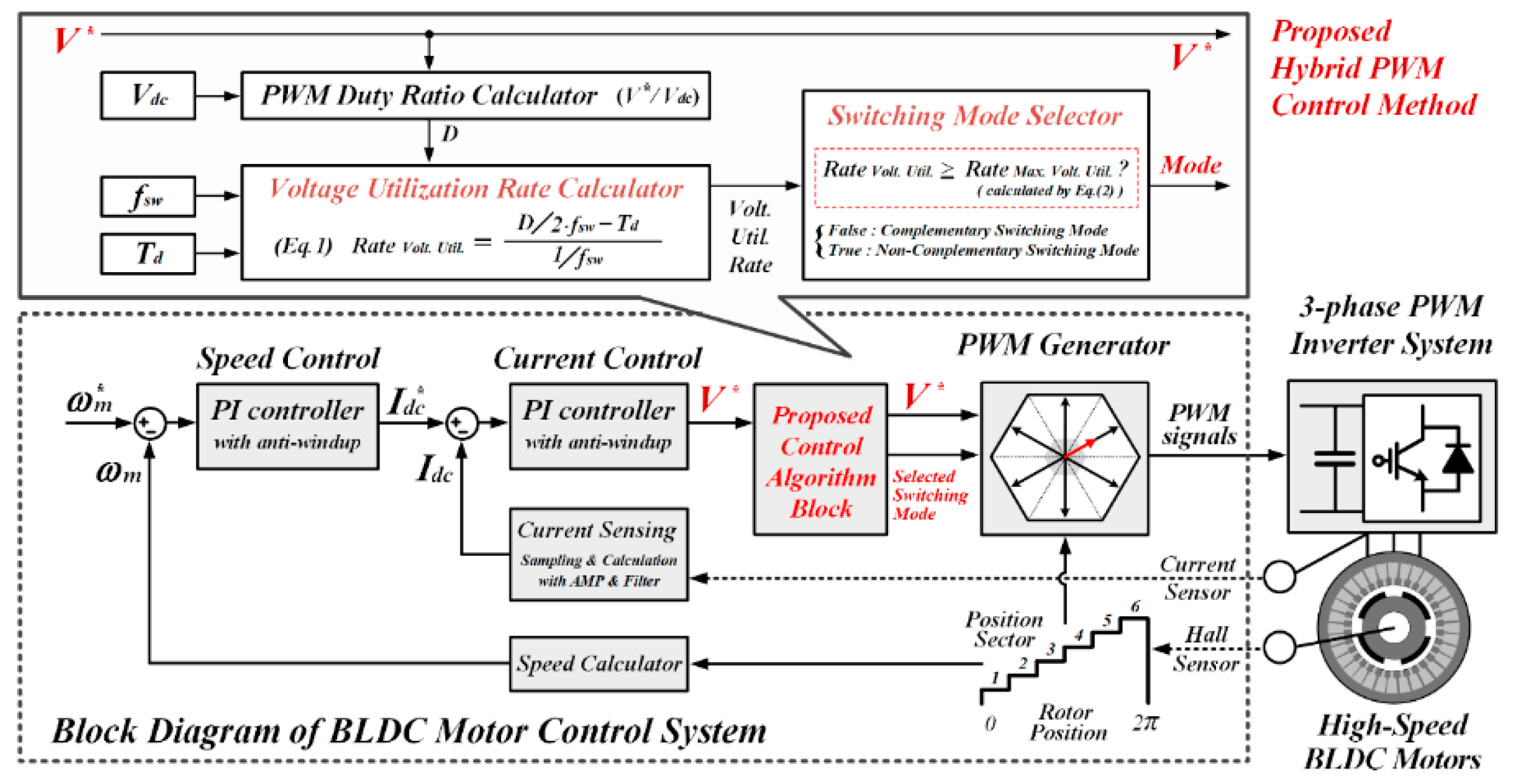
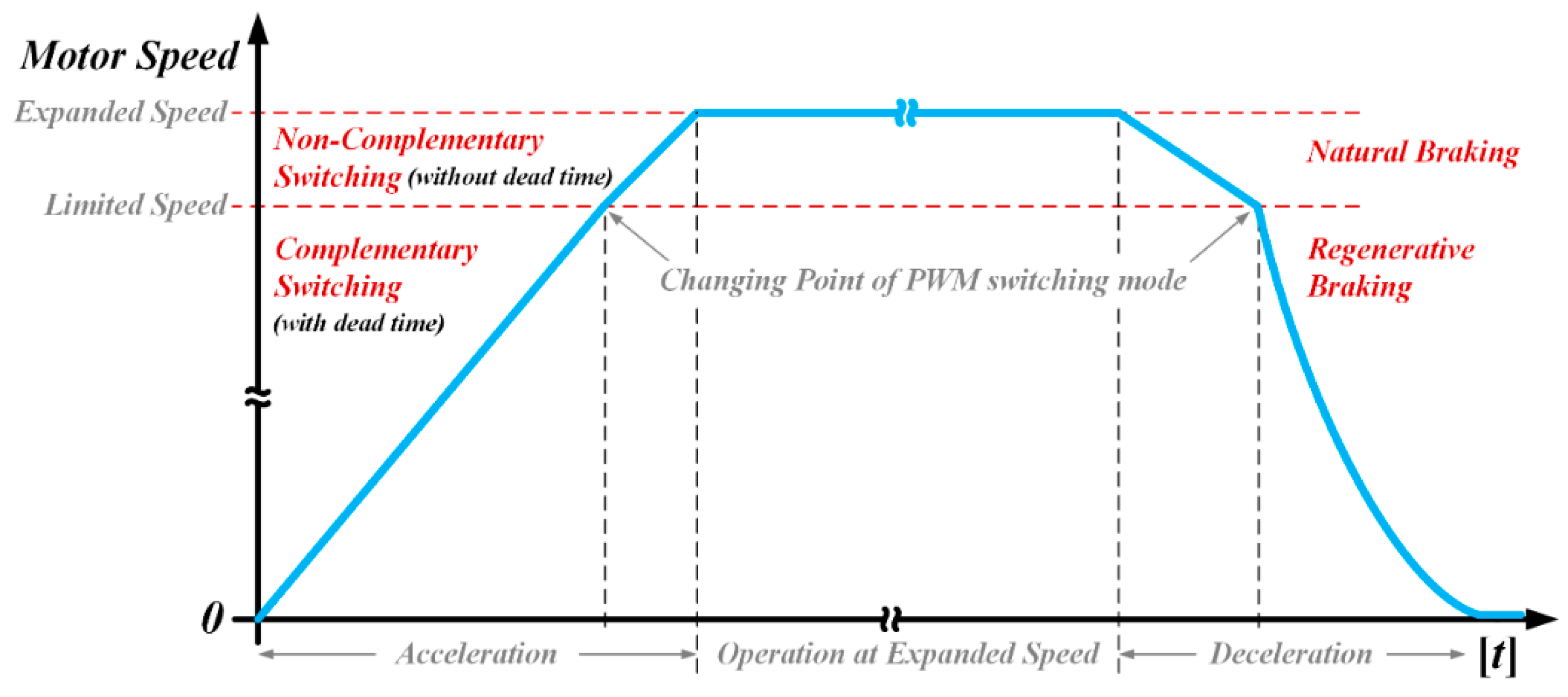
3. Proposed Hybrid PWM Control Method

In order to expand the operating speed range of the high-speed BLDC motor system in vehicles in which the inverter supply voltage is limited, this paper proposes a control algorithm that selectively uses the two switching modes of the H-PWM-L-PWM method depending on the operating region. Figure 4 presents the overall control block diagram for the three-phase BLDC motor drive system to which the proposed PWM control algorithm has been applied. The current and voltage references are generated from the speed and current controllers, respectively, and are modulated to generate PWM signals. This entire control loop is the same as the general three-phase BLDC motor control algorithm [23,24,25,26].
The proposed control block is added between the voltage reference and the PWM signal generator. In the proposed control block, the voltage utilization rate according to the voltage reference is calculated using Equation (1). The PWM method is selected by verifying whether the calculated value is greater or smaller than the maximum voltage utilization rate calculated by Equation (2). Here, the switching frequency and dead time used in the equation are predetermined constant values that are being applied in the system.
By using the proposed control algorithm, as shown in Figure 5, the high-speed BLDC motor can be operated in four-quadrants up to the limited operating speed with the maximum voltage utilization being limited by the dead time used in the complementary H-PWM-L-PWM method. For speeds above the limited operating speed, it is possible to increase the voltage utilization rate and expand the operating speed range by using the non-complementary H-PWM-L-PWM method without applying a dead time. During the deceleration operation, the BLDC motor speed is reduced by natural braking because the non-complementary H-PWM-L-PWM method cannot operate in the quadrants. However, the fast deceleration operation is possible because the complementary H-PWM-L-PWM method can switch from limited operation speed to stopping.

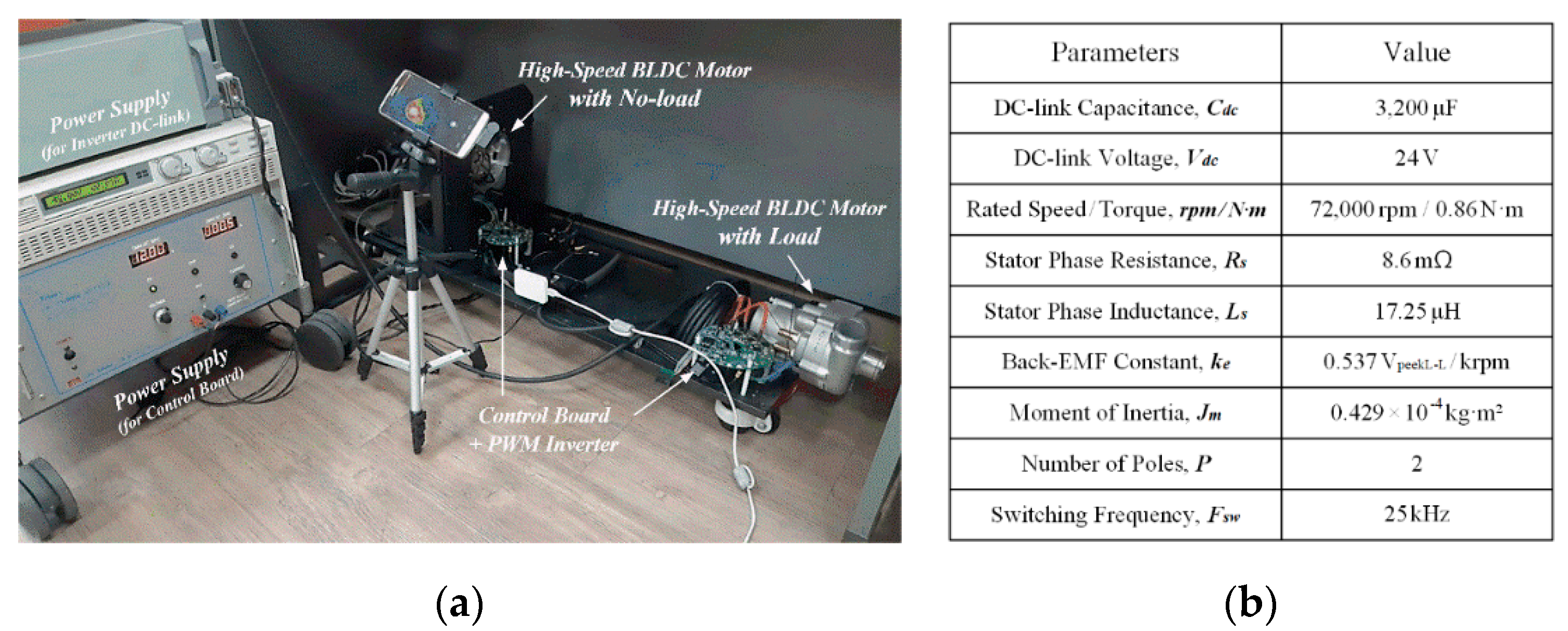
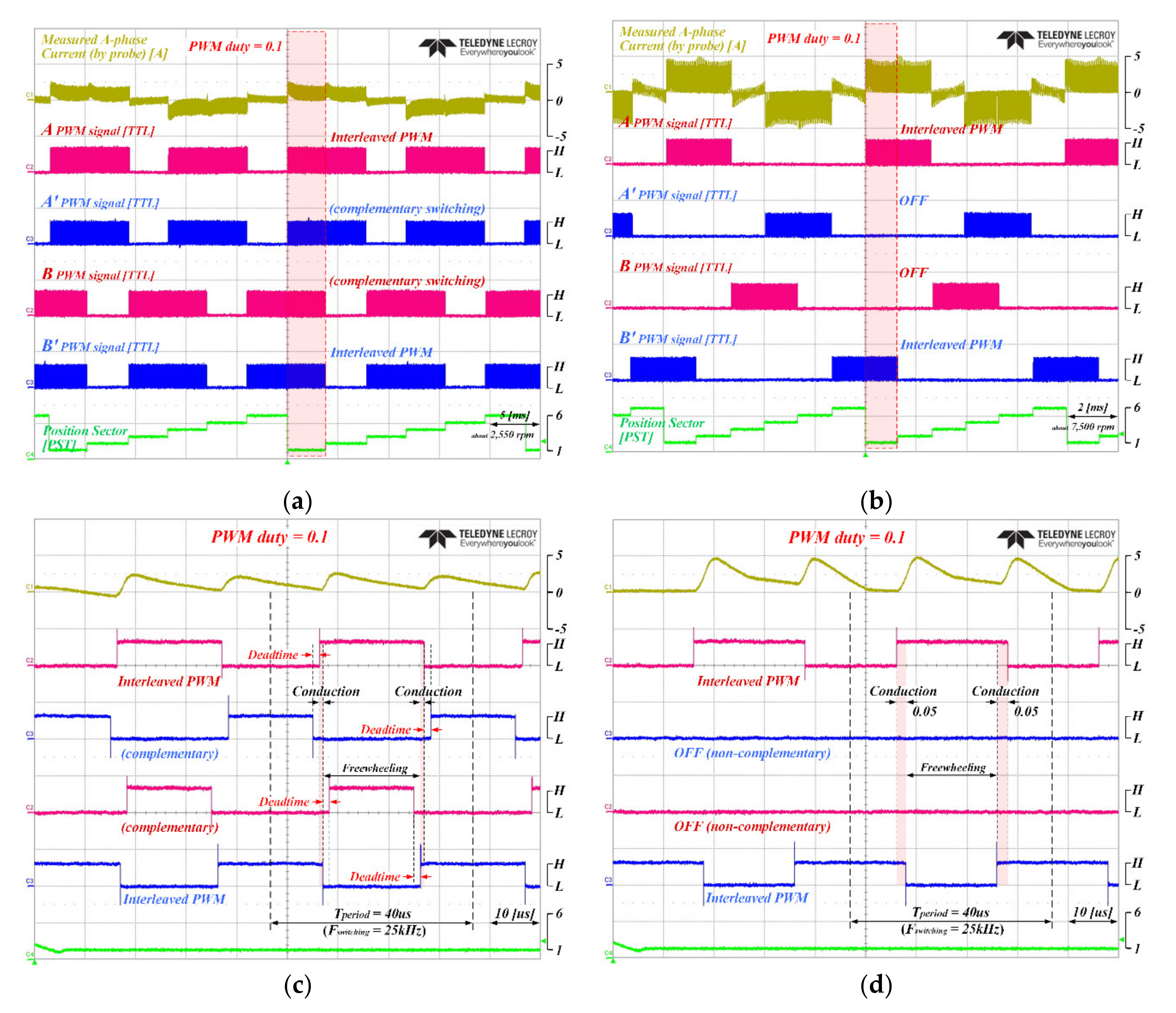
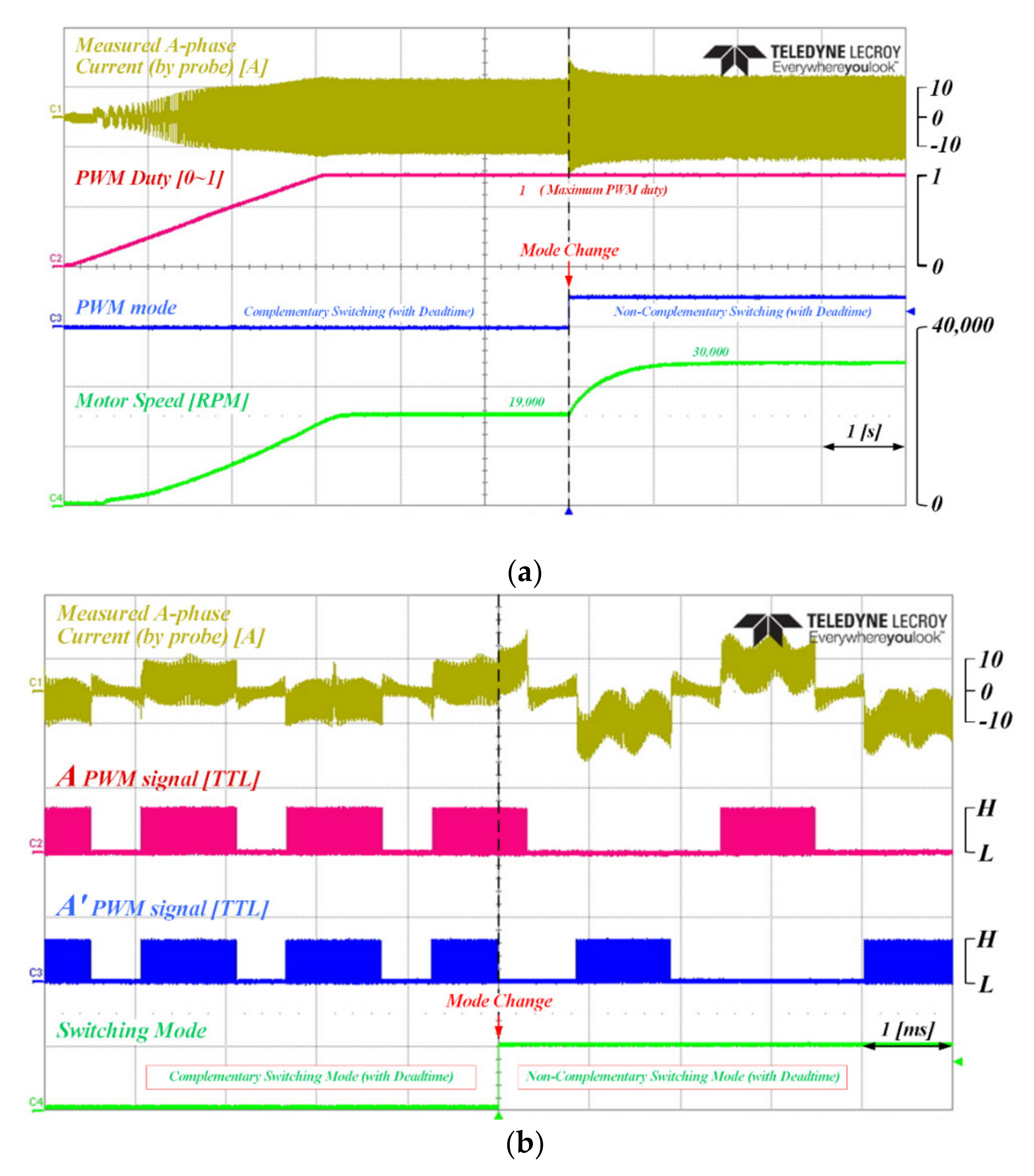
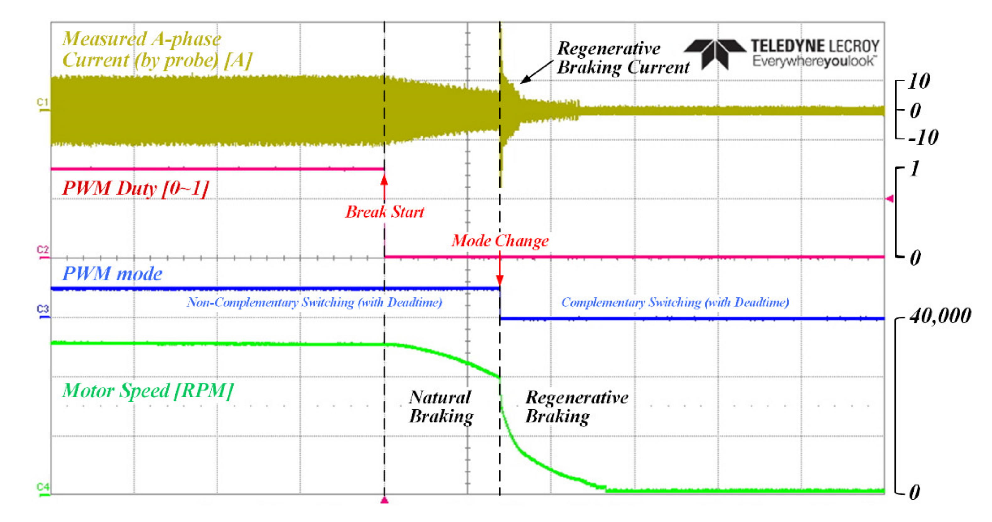
4. Experimental Results and Discussion

In this paper, an experiment was performed in order to verify the performance of the proposed control method in a high-speed BLDC motor system for a vehicle. Figure 6a shows the 6.5-kW electric supercharger system (high-speed electric compressor) designed and built for the experiment. The three-phase high-speed BLDC motor and inverter control board are integrated into the supercharger system. Further, Figure 6b presents the electrical specifications of the system. (For safety, the applied DC-link voltage and the maximum operating speed were reduced by half.).
Figure 7 shows the waveforms of the PWM pattern, phase current, and rotor position of the H-PWM-L-PWM methods for two switching modes. Figure 7a,b illustrate the results of the complementary and non-complementary switching modes, respectively, and Figure 7c,d show the waveforms enlarged in Position Sector 1 of Figure 7a,b, respectively. Since the BLDC motor is operated by the A-phase upper and B-phase lower switches in Position Sector 1, the PWM signals for the A- and B-phase switches have been presented. The switching frequency is 25 kHz (one switching cycle is 40 μs, indicated by the dotted line), the PWM duty ratio is 0.1, the applied dead time is 1.33 μs, and both switching modes were operated under the same conditions. For the 0.1 PWM duty ratio, the total PWM ON time is 4 μs within a 40-μs switching period. However, in the H-PWM-L-PWM method, the ON time is divided into two intervals, which results in one ON time being 2 μs.
In the complementary switching mode of Figure 7a,c, a dead time of 1.33 μ s is applied, so the actual conduction time is 0.67 μs. On the other hand, in the non-complementary switching mode of Figure 7b,d, the dead time is not applied, which means that the entire 2 μs PWM ON time is used as the actual voltage output time. It can be confirmed that a difference occurs in the actual conduction time and the voltage utilization rate depending on whether the dead time is used under the same duty ratio condition. In addition, a difference also occurs in the conduction current and operation speed.
Figure 8 displays the experimental results of the BLDC motor from start to the limited and expanded speeds using the proposed hybrid PWM control algorithm. The figure presents the waveforms of the measured phase current, applied voltage, switching mode, and operating speed. Figure 8a is the waveform for the entire operation region, while Figure 8b is the enlarged waveform of the phase current and the PWM pattern at the time of switching mode conversion. From the start to the limited speed on the left side of Figure 8a, the motor speed increases as the applied voltage increases using the H-PWM-L-PWM method with the complementary switching mode. Then, when the applied voltage (PWM duty ratio) reaches its maximum value, the motor speed is limited to a restricted value.
At this time, the PWM switching mode automatically changes from the complementary switching mode to the non-complementary switching mode due to the proposed control algorithm. In order to display a clear difference, the PWM switching mode was set to change after about 2.5 s from the limited time point. Although the maximum applied voltage (or PWM duty ratio) remains the same, the speed of the motor increases. This is because the dead time is not applied when using the non-complementary switching mode and, thus, the actual conduction time and voltage utilization rate increase. Figure 8b is an enlarged waveform of the change point of the complementary/non-complementary switching mode and, in addition, shows the A-phase upper and lower PWM signals. Before the switching mode changes, the upper and lower PWM signals are being generated complementarily, while the non-complementary PWM signal is generated by changing the switching mode.
Figure 9 presents the experimental results from the expanded speed to the limited speed and the stopping of the BLDC motor using the proposed hybrid PWM method. The reference voltage becomes “0” to stop (or decelerate) the motor during expanded speed operation. In the non-complementary switching mode in which regenerative braking is not possible, the speed gradually decreases through natural braking. After that, when the switching mode changes to the complementary switching mode, rapid deceleration is possible with the generation of a regenerative current. Therefore, as shown in the experimental results, by using the proposed control algorithm, the BLDC motor was operated by selectively using a complementary switching mode capable of four-quadrant operation and a non-complementary switching mode capable of expanding the speed range.
This paper proposed a control algorithm that selectively uses two switching modes of the H-PWM-L-PWM method depending on the operating region in order to increase the output performance of a high-speed BLDC motor for a vehicle. Additionally, the experimental results present the effectiveness and feasibility of the proposed method. Discussions on the experimental results were presented together in the description of each experimental result. In these experimental results, the indicator of the increase in inverter output power is the increased motor speed. The load torque of high-speed BLDC motors is almost constant in automotive compressors. Therefore, only the increased speed was adopted as the indicator of output performance improvement, and the motor speed before and after the application of the proposed control algorithm was shown comparatively as a result. However, in other vehicle motor systems with large load fluctuations, the increased power output of the inverter by the proposed control algorithm is transmitted not only to the output motor speed but also to the output motor torque. Therefore, in order to improve the practicality and effectiveness of the proposed control algorithm, it is necessary to apply the proposed control algorithm to other motor systems with large load fluctuations and to experimentally check both inverter output, motor speed and torque changes. This is an additional study of this paper to be carried out later.

5. Conclusions

In this paper, in order to expand the operating speed range in the high-speed BLDC motor system of a vehicle in which the inverter supply voltage is limited, a control algorithm was proposed that selectively uses the H-PWM-L-PWM method with complementary or non-complementary switching depending on the operating region. The operation and electrical characteristics of the various PWM methods of BLDC motors were analyzed, and the optimal PWM methods for improving the control performance of high-speed BLDC motors were summarized. In addition, the relationship between the switching frequency, dead time, and voltage utilization was mathematically analyzed. Based on the results of this analysis, the proposed control algorithm automatically changed the switching mode according to the operation region through the calculated voltage utilization rate. Accordingly, the operating speed of the high-speed BLDC motor could be increased. The control algorithm proposed in this paper was verified through the experimental results on the designed and manufactured high-speed BLDC motor system for vehicles.
The proposed control method, which can expand the operating speed range without increasing the DC-link voltage, can be applied to solve the problem of insufficient supply power that can occur in the actual development process. It can be practically applied not only in vehicle motor systems but also in various inverter system environments where the supply DC-link voltage is limited.

Author Contributions

Methodology, H.-J.K.; software, H.-J.K. and H.-S.P.; validation, H.-J.K. and H.-S.P.; formal analysis, H.-J.K.; data curation, J.-M.K.; writing—original draft preparation, H.-J.K. and H.-S.P.; writing—review and editing, J.-M.K.; visualization, H.-S.P.; project administration, J.-M.K. All authors have read and agreed to the published version of the manuscript.

Funding

This research received no external funding.

Acknowledgments

This work was supported by BK21PLUS, Creative Human Resource Development Program for IT Convergence.

Conflicts of Interest

The authors declare no conflict of interest.

References

  1. Lee, W.; Schubert, E.; Li, Y.; Li, S.; Bobba, D.; Sarlioglu, B. Overview of electric turbocharger and supercharger for downsized internal combustion engines. IEEE Trans. Transp. Electrif. 2017, 3, 36–47. [Google Scholar] [CrossRef]
  2. Lequesne, B. Automotive electrification: The nonhybrid story. IEEE Trans. Transp. Electrif. 2015, 1, 40–53. [Google Scholar] [CrossRef]
  3. Johneric, L. Automotive 48-volt technology: Chapter 4. 48-volt electrification enabling vehicle efficiency. SAE Int. 2016, 16–18. [Google Scholar] [CrossRef]
  4. Moghaddam, R.R. High speed operation of electrical machines, a review on technology, benefits and challenges. In Proceedings of the IEEE ECCE 2014, Pittsburgh, PA, USA, 14–18 September 2014. [Google Scholar]
  5. Gerada, D.; Mebarki, A.; Brown, N.L.; Gerada, C.; Cavagnino, A.; Boglietti, A. High speed electrical machines: Technologies, trends and developments. IEEE Trans. Ind. Electron. 2014, 61, 2946–2959. [Google Scholar] [CrossRef]
  6. Tavernier, S.; Equoy, S. Design and characterization of an E-booster driven by an high speed brushless DC motor. SAE Int. J. Passenger Cars-Electron. Elect. Syst. 2013, 6, 360–365. [Google Scholar] [CrossRef]
  7. Pillay, P.; Krishnan, R. Application characteristics of permanent magnet synchronous and brushless dc motors for servo drives. IEEE Trans. Ind. Appl. 1991, 27, 986–996. [Google Scholar] [CrossRef] [Green Version]
  8. Zhao, N.; Schofield, N.; Yang, R.; Gu, R. Investigation of DC-link voltage and temperature variations on EV traction system design. IEEE Trans. Ind. Appl. 2017, 53, 3707–3718. [Google Scholar] [CrossRef]
  9. Choi, M.-E.; Lee, J.-S.; Seo, S.-W. Real-time optimization for power management systems of a battery/ supercapacitor hybrid energy storage system in electric vehicles. IEEE Trans. Vehicular Technol. 2014, 63, 3600–3611. [Google Scholar] [CrossRef]
  10. Van der Geest, M.; Polinder, H.; Ferreira, J.A.; Christmann, M. Power density limits and design trends of high-speed permanent magnet synchronous machines. IEEE Trans. Transp. Electrif. 2015, 1, 266–276. [Google Scholar] [CrossRef]
  11. Zwyssig, C.; Round, S.D.; Kolar, J.W. An ultrahigh-speed, low power electrical drive system. IEEE Trans. Ind. Electron. 2008, 55, 577–585. [Google Scholar] [CrossRef]
  12. Fakham, H.; Djemai, M.; Busawon, K. Design and practical implementation of a back-emf sliding-mode observer for a brushless dc motor. IET Electric Power Appl. 2008, 2, 353–361. [Google Scholar] [CrossRef]
  13. Kim, S.-I.; Lee, G.-H.; Hong, J.-P.; Jung, T.-U. Design process of interior PM synchronous motor for 42-V electric air-conditioner system in hybrid electric vehicle. IEEE Trans. Magn. 2008, 44, 1590–1593. [Google Scholar]
  14. Pillay, P.; Krishnan, R. Modeling, simulation, and analysis of permanent-magnet motor drive, Part II: The brushless DC motor drive. IEEE Trans. Ind. Appl. 1989, 25, 274–279. [Google Scholar] [CrossRef]
  15. Wang, J.; Chen, C.; Chorian, S.; Huang, Y. Auxiliary power supply for hybrid electric vehicles. In Proceedings of the IEEE PESC, Orlando, FL, USA, 17–21 June 2007. [Google Scholar]
  16. Evzelman, M.; Rehman, M.M.; Hathaway, K.; Zane, R.; Costinett, D.; Maksimovic, D. Active balancing system for electric vehicles with incorporated low-voltage bus. IEEE Trans. Power Electron. 2016, 31, 7887–7895. [Google Scholar] [CrossRef]
  17. Tani, A.; Camara, M.B.; Dakyo, B.; Azzouz, Y. DC/DC and DC/AC converters control for hybrid electric vehicles energy management-ultracapacitors and fuel cell. IEEE Trans. Ind. Inform. 2013, 9, 686–696. [Google Scholar] [CrossRef]
  18. Hegazy, O.; Barrero, R.; Van Mierlo, J.; Lataire, P.; Omar, N.; Coosemans, T. An advanced power electronics interface for electric vehicles applications. IEEE Trans. Power Electron. 2013, 28, 5508–5521. [Google Scholar] [CrossRef]
  19. Anun, M.; Ordonez, M.; Zurbriggen, I.G.; Oggier, G.G. Circular switching surface technique: High-performance constant power load stabilization for electric vehicle systems. IEEE Trans. Power Electron. 2015, 30, 4560–4572. [Google Scholar] [CrossRef]
  20. Camara, M.B.; Gualous, H.; Gustin, F.; Berthon, A.; Dakyo, B. DC/DC converter design for supercapacitor and battery power management in hybrid vehicle applications—Polynomial control strategy. IEEE Trans. Ind. Electron. 2010, 57, 587–597. [Google Scholar] [CrossRef]
  21. Thounthong, P.; Chunkag, V.; Sethakul, P.; Davat, B.; Hinaje, M. Comparative study of fuel-cell vehicle hybridization with battery or supercapacitor storage device. IEEE Trans. Vehicular Technol. 2009, 58, 3892–3904. [Google Scholar] [CrossRef]
  22. Chen, G.; Deng, Y.; Dong, J.; Hu, Y.; Jiang, L.; He, X. Integrated multiple-output synchronous buck converter for electric vehicle power supply. IEEE Trans. Vehicular Technol. 2017, 66, 5752–5761. [Google Scholar] [CrossRef]
  23. Elevich, L.N. 3-Phase BLDC Motor Control with Hall Sensors Using56800/E Digital Signal Controllers; Application Note, Freescale Semiconductor Inc.: Austin, TX, USA, 2005. [Google Scholar]
  24. Song, K.Y.; Jin, Y.S.; Kim, H.W.; Cho, K.Y.; Han, B.M. Position control of BLDC motor with modified bipolar PWM for clutch system of PHEV. In Proceedings of the IEEE ECCE Asia Downunder, Melbourne, Australia, 3–6 June 2013. [Google Scholar]
  25. Sathyan, A.; Milivojevic, N.; Lee, Y.-J.; Krishnamurthy, M.; Emadi, A. An FPGA-based novel digital PWM control scheme for BLDC motor drives. IEEE Trans. Ind. Electron. 2009, 56, 3040–3049. [Google Scholar] [CrossRef]
  26. Rodriguez, F.; Emadi, A. A novel digital control technique for brushless DC motor drives. IEEE Trans. Ind. Electron. 2007, 54, 2365–2373. [Google Scholar] [CrossRef]
  27. Joice, C.S.; Paranjothi, S.R.; Kumar, V.J.S. Digital control strategy for four quadrant operation of three phase BLDC motor with load variations. IEEE Trans. Ind. Inform. 2013, 9, 974–982. [Google Scholar] [CrossRef]
  28. Yang, M.-J.; Jhou, H.-L.; Ma, B.-Y.; Shyu, K.-K. A cost-effective method of electric brake with energy regeneration for electric vehicles. IEEE Trans. Ind. Electron. 2009, 56, 2203–2212. [Google Scholar] [CrossRef]
  29. Lai, Y.-S.; Lin, Y.-K. Quicken the pulse. IEEE Ind. Appl. Mag. 2008, 14, 34–44. [Google Scholar] [CrossRef]
  30. Li, Q.; Huang, H.; Yin, B. The study of PWM methods in permanent magnet brushless DC motor speed control system. In Proceedings of the Int. Conf. on Elect. Mach. and Syst, Wuhan, China, 17–20 October 2008. [Google Scholar]
  31. Valle, R.L.; Almeida, P.M.; Ferreira, A.A.; Barbosa, P.G. Unipolar PWM predictive current-mode control of a variable-speed low inductance BLDC motor drive. IET Electric Power Appl. 2017, 11, 688–696. [Google Scholar] [CrossRef]
  32. Pindoriya, R.M.; Mishra, A.K.; Rajpurohit, B.S.; Kumar, R. An analysis of vibration and acoustic noise of BLDC motor drive. In Proceedings of the IEEE PESGM, Portland, OR, USA, 5–10 August 2018. [Google Scholar]
  33. Baszynski, M.; Pirog, S. Unipolar modulation for a BLDC motor with simultaneously switching of two transistors with closed loop control for four-quadrant operation. IEEE Trans. Ind. Inform. 2018, 14, 146–155. [Google Scholar] [CrossRef]
  34. Kim, H.W.; Shin, H.K.; Mok, H.S.; Lee, Y.K.; Cho, K.Y. Novel PWM method with low ripple current for position control applications of BLDC motors. J. Power Electron. 2011, 11, 726–733. [Google Scholar] [CrossRef]
  35. Park, S.J.; Park, H.W.; Lee, M.H.; Harashima, F. A new approach for minimum-torque-ripple maximum-efficiency control of BLDC motors. IEEE Trans. Ind. Electron. 2000, 47, 109–114. [Google Scholar] [CrossRef]
  36. Choi, J.-W.; Sul, S.-K. Inverter output voltage synthesis using novel dead time compensation. IEEE Trans. Power Electron. 1996, 11, 221–227. [Google Scholar] [CrossRef]
  37. Zhao, Y.; Qiao, W.; Wu, L. Dead-time effect analysis and compensation for a sliding-mode position observer-based sensorless IPMSM control system. IEEE Trans. Ind. Appl. 2015, 51, 2528–2535. [Google Scholar] [CrossRef]
Figure 1. Three-phase high-speed brushless DC (BLDC) motor inverter system: (a) equivalent circuit; (b) three-phase current and back-EMF waveforms.
Energies 13 05212 g001
Figure 2. Example of PWM patterns in one switching cycle of Position Sector 1: (a) unipolar type PWM method; (b) bipolar type PWM method. V* is the value of reference voltage for the PWM control. This value is output from the current controller and used for PWM generation.
Energies 13 05212 g002
Figure 3. The PWM pattern of the H-PWM-L-PWM method in one switching cycle of Position Sector 1: (a) complementary switching mode; (b) non-complementary switching mode. V* is the value of reference voltage for the PWM control. This value is output from the current controller and used for PWM generation.
Energies 13 05212 g003
Figure 4. Block diagram of the BLDC motor control system with the proposed control algorithm. V* is the value of reference voltage for the PWM control. This value is output from the current controller and used for PWM generation.
Energies 13 05212 g004
Figure 5. Expanded operating range of the high-speed BLDC motor using proposed control algorithm.
Energies 13 05212 g005
Figure 6. Experimental high-speed BLDC motor drive system: (a) experimental setup; (b) electrical parameters.
Energies 13 05212 g006
Figure 7. PWM pattern of the H-PWM-L-PWM method according to position sector: (a) complementary switching mode; (b) non-complementary switching mode; (c) enlarged waveform in Position Sector 1 of Figure 7a; and (d) enlarged waveform in Position Sector 1 of Figure 7b.
Energies 13 05212 g007
Figure 8. Experimental results of the acceleration operation using the proposed control algorithm (from start to limited speed and expanded speed): (a) entire operation region; (b) enlarged waveform of the phase current and PWM pattern at the time of switching mode conversion.
Energies 13 05212 g008
Figure 9. Experimental results of the deceleration operation using the proposed control algorithm (from expanded speed to limited speed and stopping).
Energies 13 05212 g009
Table 1. Electrical and operation characteristics of various PWM methods for BLDC motors.
PWM TypeUnipolar PWMBipolar PWMH-PWM-L-PWM
Switching modenon-complementarycomplementarycomplementarynon-complementary
Dead timenot usedusedusednot used
Ratio of voltage fluctuation
between PWM ON and OFF
121
Number of conduction
(per one switching period)
112
Ratio of phase current
ripple amplitude
120.5
Four-quadrant operation and regenerative brakingimpossiblepossiblepossibleimpossible
Maximum voltage
utilization rate (Equation (2))
11 − Td × fsw0.5 − Td × fsw1

