Abstract
Various efforts have been made worldwide to reduce energy use for heating, ventilation, and air-conditioning (HVAC) systems and lower carbon dioxide (CO2) emissions. Research and development are essential to ensuring the efficient use of renewable energy systems. This study proposes a multiple sources and multiple uses heat pump (MMHP) system that can efficiently respond to heating, cooling, and domestic hot water (DHW) loads using multiple natural heat sources. The MMHP system uses ground and air heat as its primary heat sources and solar heat for heat storage operations and ground temperature recovery. For the efficient use of each heat source, it also determines the heat source required for operation by comparing the heat source temperatures in the same time zone. A model for predicting the heat source temperatures, electricity use, and coefficient of performance (COP) was constructed through simulation. To analyze the efficiency of the proposed system by comparing the existing air source heat pump with ground source heat pump systems, a performance analysis was conducted by setting regional and system configurations as case conditions. The results demonstrate that the electricity use of the MMHP system was 13–19% and 1–3% lower than those of air source heat pump (ASHP) and ground source (GSHP) systems, respectively. In addition, the MMHP system was the most favorable in regions with a low heating load.
1. Introduction
To reduce energy use and associated carbon dioxide (CO2) emissions in the building sector, various studies focusing on heating, ventilation and air conditioning (HVAC) systems have been conducted worldwide. Specifically, the South Korean government has set their renewable energy installation rate to 30% for newly constructed public buildings with a total floor area of 1000 m2 or higher [1]. It also recently published the Green New Deal Policy [2] and established a plan to install renewable energy facilities in existing public buildings. The government provides subsidies to residential buildings in which renewable energy systems are installed according to the capacity of the systems. Therefore, there is a growing demand for renewable energy, and it is essential to develop technologies for the construction of efficient renewable energy systems.
The ground source heat pump (GSHP) system is a renewable energy system that uses the ground, which can have favorable temperature conditions relative to the air temperature, as a source of heating/cooling for buildings because it is a stable temperature zone. The continuous operation and long-term use of GSHP, however, can cause changes in ground temperature around the borehole. In other words, the efficiency of the system decreases if sufficient time for ground temperature recovery is not given. Various studies have been conducted to prevent the reduction in efficiency by hybrid systems.
Methods for increasing the efficiency of heat pump systems have been developed by combining GSHP and solar-thermal systems [3,4,5,6,7,8,9,10,11,12,13,14,15]. Through the combination of the GSHP system and PVT, the heat of PVT can be stored in a heat storage tank or used to allow the underground temperature to recover. In a system that combined GSHP and photovoltaic thermal (PVT) systems, the power generation efficiency of PV was increased by supplying the relatively low temperature of the ground to the bottom of the PVT panel [3]. Xi [4] compared the performance of a solar assisted ground source heat pump (SAGSHP) system with that of a GSHP system. The COP of the SAGSHP system was 26% higher than that of the GSHP system. After operation for 20 years, the heat pump COP of the SAGSHP system was 4.18, and that of the GSHP system was 3.73. Bae [5] devised a design method in which an auxiliary heat storage tank (HST) was placed in the SAGSHP system and the heat produced by a solar source could be used for the water inlet temperature of the heat pump. In the study, energy use was analyzed by comparing the developed design method with the existing design method. Razavi [6] analyzed COP and electricity use according to the SAGSHP system configuration. Among them, the method in which the circulating water of GSHP passed through the ground heat exchanger and the tube of PVT, and flowed into GSHP was the most efficient. This method can reduce energy use by 8.4% compared to conventional GSHP systems. Lazzarin [7] compared the performance of SAGSHP and GSHP systems and found that the former had a stronger performance. They also found that the use of a solar heat source and reducing the length of the ground heat exchanger led to a lower investment cost than that of the GSHP system. Yang [8] developed a system that uses solar heat and the ground as heat sources and conducted research on the optimal number of boreholes and solar collector areas for the SAGSHP system. The length of the ground heat exchanger had a significant impact on system efficiency, but the size of the HST had an insignificant influence. Xia [9] proposed an optimal control method for the SAGSHP system and formulated a control strategy using a simplified adaptive mode and a genetic algorithm for the efficient control of a PVT system. Through the optimal control strategy, energy use was reduced by 7.8% for cooling and 7.1% for heating compared to the existing control method. In addition, the solar power generated was increased by 4.4 and 6.2%. Emmi [10] analyzed the ground temperature and performance for ten years according to the configuration of the SAGSHP system. When the solar heat collector of the SAGSHP system was used for ground temperature recovery operation and building cooling/heating, more efficient operation compared to a conventional GSHP system was shown to be possible. In addition, energy efficiency remained constant for ten years. even when half the initial value of the ground heat exchanger was used. Bakirci [11] installed a SAGSHP system in the Erzurum cold climate area and analyzed the performance of the system through experiments. The heat pump COP ranged from 3.0 to 3.4 and the system COP ranged from 2.7 to 3.0, confirming that the SAGSHP system supplied sufficient residential heating in the Erzurum area. Eslami-nejad [12] developed a double U-tube system in which one U-tube was connected to a heat pump and the other to a solar heat collector. In the developed system, the length of the ground heat exchanger could be reduced by 17.6–33.1% compared to an existing GSHP system.
Moreover, studies were conducted to improve efficiency through the combined use of air and ground sources. [13,14]. Nam [13] developed a heat pump that used both groundwater and air as heat sources and analyzed its performance. The COP of the developed heat pump system was higher than that of the single heat source system, and the system had a positive effect on the recovery of the groundwater temperature. Corberán [14] developed a heat pump that used ground heat and air as its heat sources. The developed heat pump system exhibited the same performance as existing GSHP systems, even when the length of the ground heat exchanger was reduced by half.
However, there are few studies [15] on hybrid systems that simultaneously use multiple natural heat sources such as solar, air and ground for heating, cooling, and providing domestic hot water in buildings. Air heat source systems can be introduced to buildings as heating and cooling systems and can reduce total system costs, even though their performance significantly depends on the local climate. There are many conditions in which the air source is more efficient than the water source, owing to the electricity use of the circulation pump or the heat loss of the piping. In view of system performance, the most efficient source in multiple sources heat pump systems should be selected based on transient conditions.
In this research, to determine the performance of multiple sources and multiple uses heat pump (MMHP) systems according to local climates, a dynamic energy simulation was conducted by an integrated simulation model with ASHP, GSHP, a solar model, and a building load model.
This study quantitatively analyzes the superiority of MMHP systems compared with conventional systems in three different climates. The system proposed in this study uses the air and ground as the main heat sources, and solar heat for the ground temperature recovery and as an auxiliary heat source. In this study, the cooling, heating, and domestic hot water (DHW) demands in each region were calculated using the TRNSYS (TRNSYS 18, Thermal Energy System Specialists, Madison, WI, USA). In addition, each system model was constructed and its annual performance analyzed. The most efficient system in each region was identified through the constructed simulation model, and additional analyses were conducted on a control method to further improve performance.
2. Description of the MMHP System
The configuration and operation method of the MMHP system are described in this section. The MMHP system was designed to meet the heating, cooling, and DHW demands of residential models. MMHP can improve system performance by selectively using a heat source with the highest energy efficiency among the three heat sources (air, ground, and solar heat). It can also prevent the efficiency reduction normally caused by the continuous operation and long-term use of ground heat. The proposed MMHP system consists of a ground heat exchanger, a heat pump, PVT, a HST, and a fan coil unit (FCU) (Figure 1).
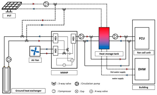
Figure 1.
Schematic diagram of MMHP.
Figure 2 shows the eight operation modes of the MMHP system. Heating is performed by three operation methods. Figure 2a shows direct heating using the ground heat exchanger, Figure 2b demonstrates direct heating using air, and Figure 2c details heating using the HST. Regarding cooling operations, only direct cooling operation was performed, as shown in Figure 2a,b. Figure 2d shows a DHW operation in which hot water is supplied using the heat of the HST. To perform heating and hot water supply using the HST, heat storage is required. Figure 2e–g shows the methods for supplying heat to the tank using ground, air, and solar heat. Solar heat is stored through the circulating water at the bottom of the solar collector (Figure 2e). The ground and air are used as the heat sources of the heat pump, and the heat produced by the heat pump is supplied to the HST (Figure 2f,g). Figure 2h shows the operation for recovering the ground temperature through heat exchange between solar heat and the cooled ground.
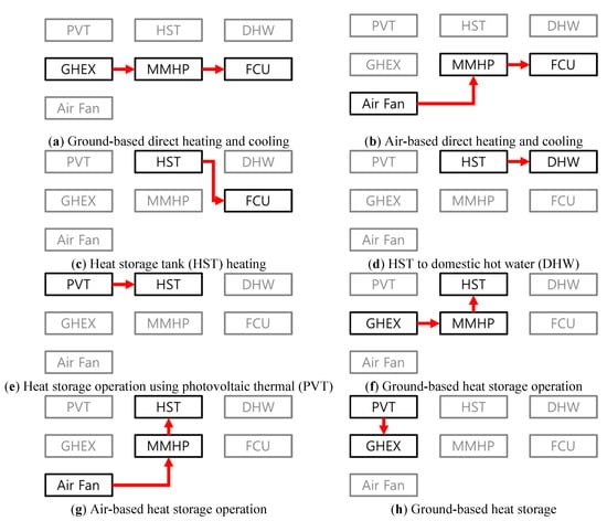
Figure 2.
Operation modes of the multiple sources and multiple uses heat pump (MMHP) system.
Figure 3 shows the operation logic of the MMHP system. The eight operation methods described above are controlled by this logic. In the winter, the indoor temperature was set to 24 ± 1 °C. During heating, priority was given to heating that uses the HST. When the temperature of the HST () decreased to 40 °C or lower, direct heating was performed using the heat pump. For direct heating that used the heat pump, the air and ground temperatures were compared; air was used as a heat source when the air temperature was 2 °C higher than the ground temperature, while ground heat was used when the air temperature was lower than the ground temperature. In the summer, the indoor temperature () was set to 26 ± 1 °C. A cooling operation using the heat pump was performed. Regarding the heat source of the heat pump, the air and ground temperatures were compared and air was used when the ground temperature () was 10 °C higher than the air temperature (). Although air was used as a heat source, the ground was used if the air temperature was 8 °C higher than the ground temperature.
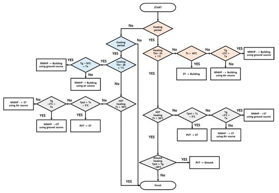
Figure 3.
MMHP system control logic.
Heat storage operations were performed both in summer and winter to supply hot water to the user. During this operation, priority was given to the heat storage operation that used PVT. This mode was used when the water outlet temperature of PVT () was more than 5 °C higher than the temperature of the HST. Otherwise, a heat storage operation was performed using the heat pump. In this instance, the heat source of the heat pump was selected using the same method as in heating. The ground heat storage operation was performed when the temperature of the HST was sufficiently high, and a heating operation was not performed in winter. When the water outlet temperature of PVT was 30 °C higher than the ground temperature, the circulating water of PVT was supplied to the ground heat exchanger to recover the ground temperature that was reduced by heating and heat storage operations.
3. Simulation Model
In this study, the simulation model was constructed to calculate the COP and electricity use of the MMHP system. The method of constructing building and system models is described in this section. First, the load of the target building was calculated through building modeling. Based on the calculated load, capacity design was performed by applying regional design standards.
3.1. Overview of the Building Model
The building model used for simulation was created by referring to the standard housing proposed by the Ministry of Land, Infrastructure and Transport of South Korea [16]. Its floor area was 140 m2. Table 1 shows the boundary conditions of the building model. The standards of South Korea [17] and Canada [18] were applied for the thermal transmittance values. In addition, the internal heating conditions (lighting, equipment, and human body) and infiltration of the building model were set by referring to ASHRAE 90.1-2004 [19]. For the amount of hot water supply, four family members were considered. The daily amount and schedule of the hot water supply were set by referring to the ASHRAE Handbook’s HVAC applications [20].

Table 1.
Load calculation conditions by region.
3.2. Heating, Cooling, and DHW Load
The load of each region was calculated based on the building model. Table 2 shows the heating and cooling peak loads of each region. The system capacity was designed based on each peak load. The detailed capacity of each system can be found in Section 3.3. Ottawa exhibited the highest heating load, followed by Seoul and Ulsan. On the other hand, Ulsan exhibited the highest cooling load, followed by Seoul and Ottawa. The DHW load was calculated based on a daily hot water supply of 252 L/day [20].
Table 2.
Heating, cooling, and DHW loads.
3.3. Modeling of the MMHP System
The MMHP system performance simulation model was constructed using TRNSYS. The constructed system calculated the amount of heat exchanged between the ground heat exchanger, PVT, heat pump, HST, and FCU, as well as their electricity use and COP. To construct the MMHP system model, a ground heat exchanger (type 557a), PVT (type 560), heat pump (type 927), HST (type 4c), and FCU (type 987) components were used. The ground heat exchanger model is the vertical U-tube type that interacts thermally with the local earth. The PVT component can calculate the production rate considering the PV back temperature and solar radiation. The heat pump model is based on the performance curve according to the entering source temperature, load temperature, source flow rate, and load flow rate. The HST model has multiple inlet and calculates heat losses according to the ambient temperature. The FCU model is a four-pipe, fan coil unit.
3.3.1. Ground Heat Exchanger Component
The ground heat exchanger component was created based on the duct ground heat storage model developed by Hellstrom [21]. The heat flow from the ground heat exchanger to the ground was determined by the ground around the ground heat exchanger and circulating water temperatures. If transient terms in the fluid are neglected, the heat balance equation for the heat carrier fluid can be defined, as shown in Equation (1).
The water outlet temperature () of the ground heat exchanger can be expressed as Equation (2).
The damping factor () can be defined as shown in Equation (3).
Here, is the volumetric heat capacity of the fluid, is the flow rate, is the heat transfer coefficient, is the fluid temperature, is the ground temperature, is the exponential function, and is the pipe length. is the water inlet temperature of the ground heat exchanger.
3.3.2. PVT Component
The PVT component consists of PV cells, an absorber plate, a tube, and back insulation. The energy received by PVT was calculated using the method presented by Duffie and Beckman [22]. PVT receives solar radiation energy and the received energy is given by Equation (4).
Some of the received energy is used by PV cells to generate power based on the photoelectric effect. The power generated by the PV cells () is calculated using Equation (5).
Here, is the transmittance-absorptance product for the solar collector, is the incidence angle modifier, is the total solar radiation, is the solar panel area, is the nominal efficiency, is the multiplier for the PV cell efficiency as a function of the cell temperature, and is the multiplier for the PV cell efficiency as a function of the incident radiation.
The absorbed energy () is the net rate at which energy is absorbed by the collector plate excluding the energy used for power generation. The absorbed energy is shown in Equation (6).
The absorbed energy is lost to the ambient conditions through convection off the top of the collector (; some is lost to the sky through radiation off the top of the collector ( and some is lost to ambient conditions through the back of the collector. The energy ( left after such losses is used for heat production in the tube. The energy used for heat production is shown in Equation (7).
3.3.3. Heat Pump Component
The heat pump of the MMHP system has two heat sources, i.e., air and water. As there is no model that can implement two heat sources in TRNSYS, MMHP was implemented by combining air-to-water and water-to-water heat pump components. The heating/cooling capacity and power of the heat pump were determined by the performance data of the heat pump manufacturer [23,24,25]. The amount of heat absorbed () by the heat pump during heating can be obtained using Equation (8).
is the heat pump heating capacity at current conditions and is the power drawn by the heat pump in the heating mode.
When heating using the ground, the water outlet temperature ( of the ground heat exchanger is determined by Equation (9). is the water inlet temperature of the ground heat exchanger, is the mass flow rate of the liquid on the source side of the heat pump, and is the specific heat of the liquid on the source side of the heat pump.
When heating using the air, the temperature of the air discharged ( from the heat pump to the atmosphere is given by Equation (10). is the air inlet temperature of the ambient, is the mass flow rate of the air on the source side of the heat pump, and is the specific heat of the air on the source side of the heat pump.
The temperature of the water outlet temperature () from the load side can be obtained using Equation (11). is the water inlet temperature of the load side, is the mass flow rate of the water on the load side of the heat pump, and is the specific heat of the water on the load side of the heat pump.
The amount of heat released ( through the heat pump during MMHP cooling can be obtained using Equation (12).
is the heat pump cooling capacity at current conditions and is the power drawn by the heat pump in cooling mode.
When ground heat is used as a heat source, the water outlet temperature of the ground heat exchanger is determined by Equation (13).
When air heat is used as a heat source, the air outlet temperature on the heat source side of the heat pump is determined by Equation (14).
The temperature of the air discharged from the load side can be obtained using Equation (15).
3.3.4. System Capacity
Table 3 shows the capacity of each component of the MMHP system. The capacity design of a system that uses multiple heat sources is not quantified, unlike the capacity design of the existing system. Therefore, the standards of the regions and previous studies were referred to [3,5,26,27]. There is a difference in average ground temperature between Canada and South Korea. Therefore, the two countries apply different standards for the design of ground heat exchangers. Ground heat exchangers were designed based on 30 W per meter in Canada [26] and 60 W per meter in South Korea [27]. The PVT installation area was set to 60% of the rooftop area as staircase rooms, elevated tanks, and outdoor units are usually installed on the roof, typically occupying 40% of the total rooftop area. The capacity of the heat pump was designed considering the safety factor in terms of building cooling and heating loads in each region. Previous studies were referred to for the circulation pump and FCU [3,5].
Table 3.
Capacity design by region.
3.4. Case Conditions
In this study, cases were created using three regions and five systems to determine the optimal heat source for each region. The regions used were Ottawa, Seoul, and Ulsan. The systems used were ASHP, GSHP, solar assisted air source heat pump (SAASHP), SAGSHP, and MMHP. Figure 4 shows a schematic diagram of each system.
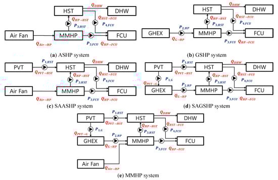
Figure 4.
Schematic diagrams of the systems used.
Figure 4a shows the schematic diagram of the ASHP system. This system consists of an air-to-water heat pump, a HST, and FCU. It uses air heat as a single heat source, and the transfer process from the heat pump to the load side is the same as the MMHP system. Figure 4b shows a schematic diagram of the GSHP system. This system consists of a ground heat exchanger, a water-to-water heat pump, a HST, and FCU. It uses ground heat as a single heat source. Figure 4c shows the SAASHP. PVT is added to the ASHP system, and PVT generates power and transfers heat to the HST. Figure 4d shows the SAGSHP system. PVT is added to the GSHP system. PVT generates power and transfers heat to the HST in the same manner as the aforementioned ASHP system. This system additionally performs heat exchange with the ground heat exchanger to recover the ground temperature when the temperature of the HST is sufficient and the water outlet temperature of PVT is higher than the ground temperature. Figure 4e shows a schematic diagram of the proposed MMHP system. It consists of an MMHP which is capable of using air and water as heat sources, a ground heat exchanger, a PVT module, a HST, and an FCU. Table 4 describes the cooling/heating, DHW, and heat storage operation of each system.
Table 4.
System operating mode.
4. Results and Discussion
4.1. Performance Characteristic Analysis
Figure 5 shows the heat production of each MMHP system heat source as well as the heat consumption on representative heating days. As the representative day was selected based on the day with the highest load, the air temperature was significantly lower than the ground temperature. In addition, the amount of heat produced using solar was also small owing to the low outside temperature. Therefore, heat was produced using ground heat as the source on the representative heating days. In addition, as the system had a HST, there was a difference between the heat production and heat consumption patterns.
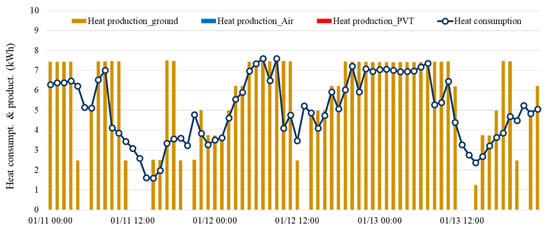
Figure 5.
Heat production and consumption on representative heating days (Seoul).
Figure 6 shows the heat production of each MMHP system heat source, as well as the heat consumption for three interseason days. Heating was required in the interseason period, but the air temperature became higher than the ground temperature. In addition, the ground temperature further decreased because ground heat was intensively used in January and February. Therefore, heat production through air was mainly observed, and heat production through PVT also significantly increased owing to the increase in outside temperature.
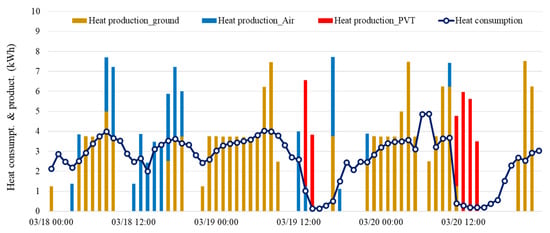
Figure 6.
Heat production and consumption on interseason days (Seoul).
4.2. System-Based Energy and Performance Analysis
Figure 7 shows the average COP values of the ASHP, GSHP, and MMHP systems by month. The heat pump COP of the GSHP system was generally higher than that of the ASHP system, but the COP of the ASHP system was higher in interseason periods (May and October). The MMHP system exhibited a higher heat pump COP than the ASHP and GSHP systems because it selectively used the efficient heat source between air heat and ground heat. The heat pump COP during the heating period was 2.89 for the ASHP system, 3.63 for the GSHP system, and 3.64 for the MMHP system. The average COP during the cooling period was 4.61 for the ASHP system, 4.90 for the GSHP system, and 5.48 for the MMHP system. This appears to be the difference caused by the DHW load that occurred during the cooling period. During the cooling period, the use of air efficiently produced heat in the heat pump to respond to the DHW load because the air temperature was higher than the ground temperature. On the other hand, the use of the ground temperature, which was lower, was favorable for responding to the building cooling load. Therefore, the MMHP system, which used both heat sources at the same time, exhibited high COP during the cooling period. The annual average heat pump COP was 3.75 for the ASHP system, 4.26 for the GSHP system, and 4.56 for the MMHP system.
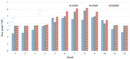
Figure 7.
Heat pump COP of the MMHP, ASHP, and GSHP systems (Seoul).
Figure 8 shows the annual electricity use of the ASHP, GSHP, SAASHP, SAGSHP, and MMHP systems, as well as the annual power production of PV. In Ottawa, the electricity use of the ASHP system was 12,011 kWh and that of the GSHP system was 9798 kWh. The GSHP system exhibited an 18% lower electricity use than the ASHP system. Meanwhile, the electricity use of the MMHP system was 9784 kWh, which was 14 kWh lower than that of the GSHP system. However, when the ground temperature recovery operation was not performed, it was 143 kWh lower. The electricity use of the SAGSHP system was 10,038 kWh. It appears that the electricity use of the SAGSHP system was higher than that of the GSHP system because the electricity use of the pump that circulated ground heat and PVT increased, owing to the ground heat storage operation. In Seoul, the electricity use of the ASHP system was 6722 kWh and that of the GSHP system was 5993 kWh. Meanwhile, the electricity use of the MMHP system was 5838 kWh, which was 13% and 3% lower than those of the ASHP and GSHP systems, respectively. Conversely, in Ulsan, the electricity use of the ASHP system was 5386 kWh and that of the GSHP system was 4945 kWh. Meanwhile, the electricity use of the MMHP system was 4780 kWh, which was 11% and 3% lower than those of the ASHP and GSHP systems, respectively.
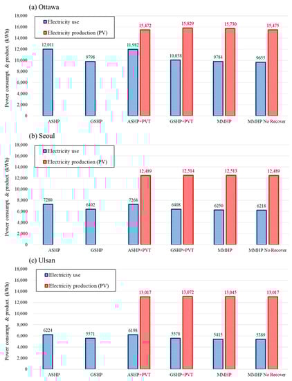
Figure 8.
Electricity use and production by the system.
In terms of annual electricity use, the efficiency of the GSHP system was significantly higher than that of the ASHP system in the region with a high heating load. When the GSHP and MMHP systems were compared, however, the MMHP system was the most favorable in regions with a low heating load. In terms of power production, the SAGSHP system was 25–357 kWh higher than the SAASHP system. This was because the SAGSHP system both recovered ground heat and reduced the back-side temperature of PVT through heat exchange with the ground. This increased the power production efficiency of PV. The power production of the MMHP system was lower than that of the SAGSHP system. This was likely because the burden of ground heat decreased for the MMHP system, as it used both air heat and ground heat, and thus, the ground temperature recovery operation using PVT decreased.
In Ottawa, when the MMHP system did not perform ground temperature recovery operations, electricity use decreased by 129 kWh, but the power production also decreased by 255 kWh, owing to the difference in PVT back-side temperature. In other words, in Ottawa, the increase in PV power production caused by the ground temperature recovery operation was larger than the use of the circulation pump for ground temperature recovery operations. Meanwhile, PV power production was higher than system electricity use for the SAASHP, SAGSHP, and MMHP systems with PVT.
Figure 9 shows the TRNSYS simulation results for 10 years of ground temperature distribution of the GSHP and MMHP systems in Ottawa. From the initial ground temperature of 10 °C, the ground temperature in ten years decreased to 8.8 °C for the GSHP system and 9.7 °C for the MMHP system. This indicated that the MMHP system could maintain ground temperature at a constant level, preventing efficiency degradation caused by a decrease in this temperature.
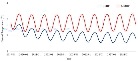
Figure 9.
Ten-year ground temperature distribution in Ottawa.
5. Conclusions
In this study, a MMHP system that uses multiple heat sources (air, ground, and solar heat) was proposed. To evaluate the efficiency of the proposed system, a simulation model was constructed by applying the proposed system to a residential model. Through the simulation model, the MMHP system was compared with existing systems (e.g., GSHP, ASHP, SAGSHP, and SAASHP) in Seoul, Ulsan, and Ottawa. The performance of the proposed system according to the control method was also compared. The results of this study can be summarized as follows:
- The MMHP system operates by comparing the temperatures of solar, air, and ground heat and by selecting an efficient heat source. Therefore, it operates using ground heat when the heating load is high because the outside temperature is low. However, the system uses both ground and air in interseason periods as the outside temperature is relatively high. In addition, the use of solar heat also increases in interseason periods owing to the outside temperature.
- When the heat pump COP values of the ASHP, GSHP, and MMHP systems were analyzed by month, the GSHP system exhibited higher values than the ASHP system, except during the interseason periods of May and October. However, in the interseason periods, the heat pump COP of the ASHP system was higher. The MMHP system had a higher COP than the GSHP and ASHP systems because it selectively used the optimal heat source between air heat and ground heat. The annual average value of heat pump COP was 3.75 for the ASHP system, 4.26 for the GSHP system, and 4.56 for the MMHP system.
- The electricity use of the MMHP system was 13–19% and 1–3% lower than those of the ASHP and GSHP systems, respectively.
- In terms of annual energy use, MMHP systems can be used efficiently in areas where both cooling and heating are required throughout the year. However, it is disadvantageous to use various heat sources in regions dominated by heating and cooling loads.
- The electricity use of the MMHP system was higher when the ground temperature recovery operation was conducted. It was determined that this was due to the electricity use of the circulation pump for ground temperature recovery. However, considering both the power generation of PVT and the recovery of the ground temperature, it is possible that performing the ground recovery operation is advantageous in terms of energy efficiency and system sustainability. When the ground temperature recovery operation was applied, electricity use increased by 129 kWh owing to the circulation pump, but the PV power production increased by 255 kWh because of the decrease in the back-side temperature of the PVT system. In addition, the decrement in ground temperature in 10 years decreased by 25% through ground temperature recovery operations.
The performance of the MMHP system was analyzed through an energy simulation capable of performing dynamic and transient analyses. The analysis results confirmed that the MMHP system could reduce electricity use compared to the existing systems in all the regions. The system was also sustainable, as it increased PV power production and minimized the ground temperature change caused by using the system. This study was conducted for residential buildings and was limited to performance analyses.
However, because the MMHP system uses multiple heat sources, to apply the MMHP system to an actual building, simplification of the complex control methods and economic analysis research are essential. Therefore, future research will conduct life-cycle cost and payback period analyses based on real-scale experiments. Lastly, research will be conducted on the optimal operation method by predicting the performance and electricity use of the MMHP system through ANN models.
Author Contributions
H.K. and Y.N.; methodology, H.K. and S.B.; software, Y.N. and S.C.; validation, H.K.; writing—original draft preparation, H.K and Y.N.; writing—review and editing, H.K.; visualization, Y.N.; supervision. All authors have read and agreed to the published version of the manuscript.
Funding
This research was supported by the MSIT (Ministry of Science, ICT), Korea, under the High-Potential Individuals Global Training Program) (2019-0-01600) supervised by the IITP (Institute for Information & Communications Technology Planning & Evaluation).
Conflicts of Interest
The authors declare no conflict of interest.
Nomenclature
| A | Area |
| C | Specific heat capacity (kJ/Kg·K) |
| Cap | Capacity (kW) |
| COP | Coefficient of performance (-) |
| e | Exponential function (-) |
| E | Energy (kW) |
| G | Total solar radiation (kJ/hr·K) |
| IAM | Incidence angle modifier (-) |
| L | Length (m) |
| m | Flow rate (kg/hr) |
| P | Power drawn (kW) |
| Q | Amount of heat (kW) |
| T | Temperature (°C) |
| X | Multiplier for photovoltaic cell efficiency (1/°C or h·m2/kJ) |
| α | Heat transfer coefficient (-) |
| η | Efficiency (-) |
| τα | Transmittance-absorptance product for solar collector (-) |
| Subscript | |
| absorbed | absorber heat |
| air | air |
| back | back |
| conv | convection |
| cooling | cooling |
| ct | cell temperature |
| f | fluid |
| gr | ground |
| heating | heating |
| i | in |
| lat | latent heat |
| load | load side |
| loss | loss energy |
| nom | nominal |
| o | out |
| p | pipe |
| pv | photovoltaic |
| rad | incidence radiation |
| source | source side |
| top | top |
| u | tube |
| Abbreviations | |
| ASHP | air source heat pump |
| COP | coefficient of performance |
| DHW | domestic hot water |
| FCU | fan coil unit |
| GHEX | ground heat exchanger |
| GSHP | ground source heat pump |
| HST | heat storage tank |
| HVAC | heating, ventilation, and air conditioning |
| MMHP | multiple sources and multiple uses heat pump |
| PV | photovoltaic |
| PVT | photovoltaic thermal |
| SAASHP | solar assisted air source heat pump |
| SAGSHP | solar assisted ground source heat pump |
References
- Korea Energy Agency (KEA). Available online: www.energy.or.kr (accessed on 26 July 2020).
- Ministry of Economy and Finance of Korea. Available online: www.moef.go.kr (accessed on 26 July 2020).
- Jeong, Y.D.; Yu, M.G.; Nam, Y. Feasibility Study of a Heating, Cooling and Domestic Hot Water System Combining a Photovoltaic-Thermal System and a Ground Source Heat Pump. Energies 2017, 10, 1243. [Google Scholar] [CrossRef]
- Xi, C.; Lin, L.; Hongxing, Y. Long term operation of a solar assisted ground coupled heat pump system for space heating and domestic hot water. Energy Build. 2011, 43, 1835–1844. [Google Scholar] [CrossRef]
- Bae, S.; Nam, Y.; da Cunha, I. Economic Solution of the Tri-Generation System Using Photovoltaic-Thermal and Ground Source Heat Pump for Zero Energy Building (ZEB) Realization. Energies 2019, 12, 3304. [Google Scholar] [CrossRef]
- Razavi, S.H.; Ahmadi, R.; Zahedi, A. Modeling, simulation and dynamic control of solar assisted ground source heat pump to provide heating load and DHW. Appl. Therm. Eng. 2018, 129, 127–144. [Google Scholar] [CrossRef]
- Lazzarin, R.M. Dual source heat pump systems: Operation and performance. Energy Build. 2012, 52, 77–85. [Google Scholar] [CrossRef]
- Macía, A.; Bujedo, L.A.; Magraner, T.; Chamorro, C.R. Influence parameters on the performance of an experimental solar-assisted ground-coupled absorption heat pump in cooling operation. Energy Build. 2013, 66, 282–288. [Google Scholar] [CrossRef]
- Xia, L.; Ma, Z.; Kokogiannakis, G.; Wang, S.; Gong, X. A model-based optimal control strategy for ground source heat pump systems with integrated solar photovoltaic thermal collectors. Appl. Energy 2018, 228, 1399–1412. [Google Scholar] [CrossRef]
- Emmi, G.; Zarrella, A.; Carli, M.D.; Galgaro, A. An analysis of solar assisted ground source heat pumps in cold climates. Energy Convers. Manag. 2015, 106, 660–675. [Google Scholar] [CrossRef]
- Bakirci, K.; Ozyurt, O.; Comakli, K.; Comakli, O. Energy analysis of a solar-ground source heat pump system with vertical closed-loop for heating applications. Energy 2011, 36, 3224–3232. [Google Scholar] [CrossRef]
- Eslami-nejad, P.; Bernier, M. Coupling of geothermal heat pumps with thermal solar collectors using double U-tube boreholes with two independent circuits. Appl. Therm. Eng. 2011, 31, 3066–3077. [Google Scholar] [CrossRef]
- Nam, Y.; Ooka, R.; Shiba, Y. Development of dual-source hybrid heat pump system using groundwater and air. Energy Build. 2010, 42, 909–916. [Google Scholar] [CrossRef]
- Corberán, J.M.; Cazorla-Marín, A.; Marchante-Avellaneda, J.; Montagud, C. Dual source heat pump, a high efficiency and cost-effective alternative for heating, cooling and DHW production. Int. J. Low Carbon Technol. 2018, 13, 161–176. [Google Scholar]
- Danny, J.; Georg, F.; Danjana, T. Simulation and performance analysis of combined parallel solar thermal and ground or air source heat pump systems. Sol. Energy 2017, 150, 500–511. [Google Scholar]
- Beginning Farmers Center. Available online: www.returnfarm.com (accessed on 26 August 2019).
- Framework Act on Low Carbon, Green Growth. Available online: www.law.go.kr (accessed on 26 August 2019).
- Natural Resources Canada. National Energy Coed of Canada for Buildings 2017; Natural Resources Canada: Hamilton, ON, Canada, 2017.
- ASHRAE. Energy Standard for Buildings Except Low-Rise Residential Buildings; ASHRAE Standard 90.1; ASHRAE: Atlanta, GA, USA, 2004. [Google Scholar]
- ASHRAE. ASHRAE Handbook HVAC Application; ASHRAE: Atlanta, GA, USA, 2011. [Google Scholar]
- Hellström, G. Duct Ground Heat Storage Model Manual for Computer Code; Department of Mathematical Physics, University of Lund: Lund, Sweden, 1989. [Google Scholar]
- Duffie, J.A.; Beckman, W.A. Solar Engineering of Thermal Process, 4th ed.; John Wiley & Sons, Inc.: Hoboken, NJ, USA, 2013. [Google Scholar]
- TRNSYS 17. HVAC Library Mathematical Reference; TESS Libs 17: Milwaukee, WI, USA, 2012; Volume 6. [Google Scholar]
- Kim, M.-H.; Kim, D.-W.; Yun, R.; Heo, H. Operational Energy Saving Potential of Thermal Effluent Source Heat Pump System for Greenhouse Heating in Jeju. Int. J. Air Cond. Refrig. 2017, 25, 1–12. [Google Scholar]
- LG Airconditioner Engineering Product Data Book. Available online: https://www.lg.com/global/business/heating-awhp (accessed on 18 September 2020).
- Government of Canada. Available online: https://www.nrcan.gc.ca (accessed on 26 July 2020).
- Korean Institute of Architectural Sustainable Environment and Building Systems (KIAEBS). Design Guide for Ground Source Heat Pump System; KIAEBS S-4: Seoul, Korea, 2016. [Google Scholar]


© 2020 by the authors. Licensee MDPI, Basel, Switzerland. This article is an open access article distributed under the terms and conditions of the Creative Commons Attribution (CC BY) license (http://creativecommons.org/licenses/by/4.0/).