1. Introduction
Compared with other types of compressors, the wear of each part of the scroll compressor has a great impact on the reliability and performance of it [
1,
2]. The axial force of the orbiting scroll is shown in
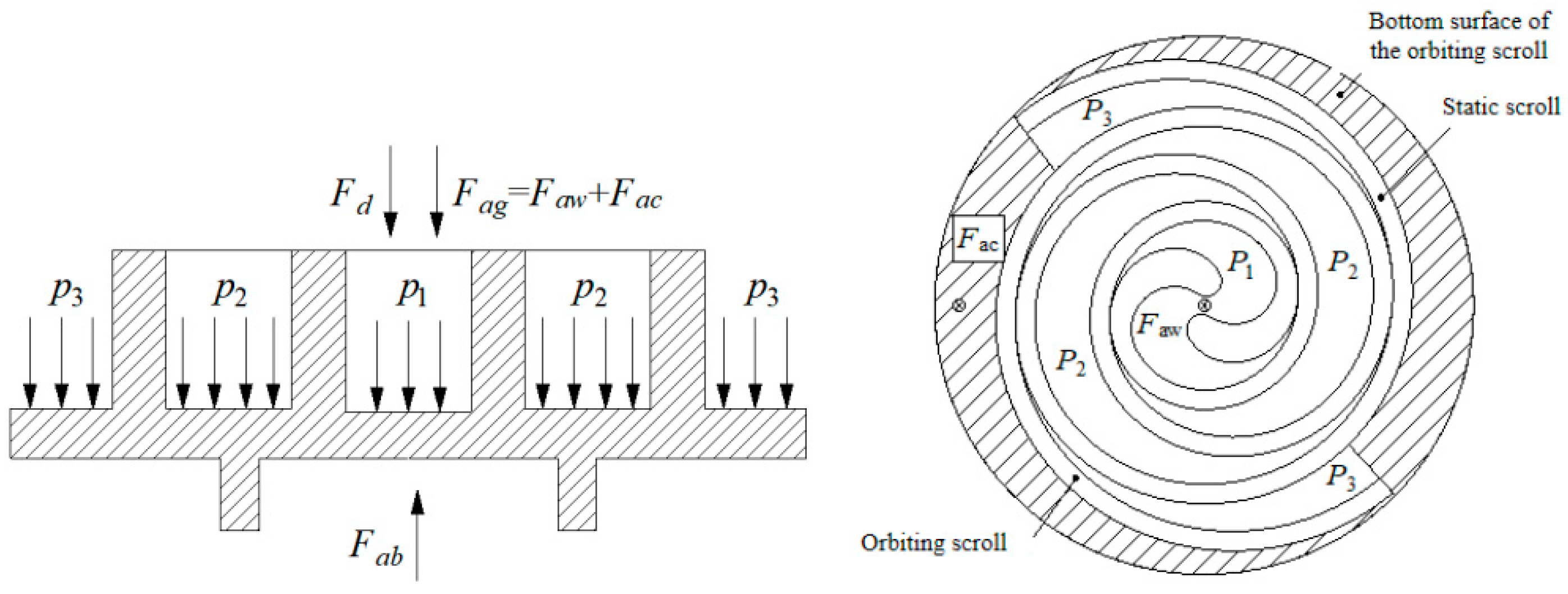
Figure 1. Under a normal operation condition, the forces acting on both sides of the orbiting scroll in the axial direction should be equal. According to the source of forces, forces on the scroll can be divided into the axial gas force
Fag, the axial back force
Fab, and the axial seal reaction force
Fd. The axial force
Fa is the difference between the axial gas force and the axial back force. In order to obtain the axial sealing force of the orbiting scroll, the axial force is generally ensured to be negative. In practical applications, a certain axial back force is often obtained through structural design. The first method is to install a thrust bearing on the back of the orbiting scroll, such as the spherical coupling used in the scroll compressor of automobile air conditioning. This structure not only provides axial back force, but also has the function of preventing rotation. However, when the scrolls are worn, they cannot be automatically compensated, so the axial back force will be reduced. The second method is to apply spring force on the back of the orbiting scroll. Although this method can solve the problem of automatic compensation when the scroll is worn, when the operating conditions of the compressor change, the axial gas force and the axial sealing force will change, but the spring force is unchanged, so it cannot be realized. For automatic compensation for the best condition, the third method is to apply oil pressure on the back of the orbiting scroll. This method can reduce the friction loss between the end surface and the bottom surface due to the lubricating effect of the oil, but as the working conditions change, the oil pressure is difficult to maintain in the appropriate range, so the axial back force is also difficult to adjust to the most appropriate status. The last method is to use a back-pressure cavity structure, that is, to apply gas force on the back of the orbiting scroll. This method is to introduce the gas in the working cavity into the back-pressure cavity by opening suitable small holes on the bottom surface of the scroll, thereby generating the axial back force and the axial sealing force [
3,
4]. If the axial back force can be kept negative, the friction loss of the scroll will be generated. If the axial sealing force is too large, the performance and reliability of the scroll compressor will be compromised. The axial back force in scroll compressor of automobile air-conditioning is obtained by using thrust bearing, but it cannot be compensated automatically after the scroll is worn and the axial force will be reduced, which will result in the increase in internal leakage of the compressor. Therefore, the balance between seal and friction loss can be obtained by reducing the friction coefficient of the orbiting scroll surface to improve the performance of the compressor. Surface treatment is an effective and direct solution.
Among many wear resistance materials, the diamond-like carbon (DLC) film has obvious advantages because of its very low friction coefficient and wear rate. Its friction coefficient is generally below 0.20, and the friction coefficient can even be reduced to 0.00549 by improving the preparation process, compared with other wear-resistant materials with general friction coefficient 0.35–0.70 [
5,
6,
7,
8]. Under normal circumstances, the diamond-like carbon film has a high hardness, and its hardness can reach up to 95 GPa, which is similar to the hardness of diamond. The hardness of the DLC film is mainly determined by the ratio of SP
3 bonds. The larger the ratio of SP
3 bonds, the higher the hardness, so the hardness of the DLC film can be adjusted [
9,
10]. When the ambient temperature is lower than 400 °C, the structure of the DLC film remains stable and the performance is good. When the ambient temperature is higher than 400 °C, the hydrogen in the hydrogen-containing DLC film will escape. What is more, it will be converted into graphite when it is higher than 500 °C [
11]. Therefore, the DLC film should not be used in high temperature environments. When the scroll compressor is working normally, the discharge temperature will not exceed 120 °C. When it is higher than 120 °C, the compressor’s thermal protector will act and stop the compressor. Therefore, the ambient temperature will not affect the DCL film on the surface of the scroll.
Many researchers are devoted to the study of surface texturing progress and deposition methods of DLC films. Dongqing He et al. revealed tribological behaviors of DLC films with different densities fabricated by unbalanced magnetron sputter technology under dry friction and liquid lubrication conditions. The double roles of wear debris and lubricating oil reservoirs, resulting from the micro-dimples, produce lower friction and wear [
12]. Chaoqian Guo et al. studied the modulation of Si on microstructure and tribomechanical properties of hydrogen-free DLC films, which was prepared by a hybrid HiPIMS (High-power Pulsed Magnetron Sputtering) and middle-frequency magnetron sputtering deposition technique [
13]. For the AISI 304 stainless steel as base material, Ping Xu et al. and Liping Wang et al. used an unbalanced magnetron sputtering method, and the method combined ion plating technology and magnetron sputtering technology, respectively, to prepare the composite films containing DLC on the aluminum alloy surface to give it a better bearing capacity, wear resistance, and self-lubricating ability [
14,
15,
16,
17]. Ting Guo et al. fabricated the Ti/Al-DLC films using a unique hybrid ion beam system [
18]. In medical applications, Xi Rao et al. used a filtered cathodic vacuum arc (FCVA) method to prepare DLC films with different C-C SP
2/SP
3 ratios to improve hemolysis rate and cytotoxicity level [
19]. Xuexing Ding et al. applied the magnetron sputtering technology to prepare DLC film to improve the tribological behavior of the SiC dry gas seal rings [
20]. Although there are plentiful research studies about the DLC film, whether it is numerical simulation or development of new composite materials, the research on DLC film in the scroll compressor to solve the friction and wear-loss problem is still insufficient due to many complicated control factors, such as suitable base materials and a reasonable coating method [
21,
22,
23,
24,
25].
In this paper, considering the unique properties of Al material and the advantages of the unbalanced magnetron sputtering method—high bonding strength, easy to control thickness and suitable for large-area coating—we coated the DLC film on the surface of the orbiting scroll by unbalanced magnetron sputtering equipment with Cr as the transition layer to reduce its friction coefficient and thus, improve the film-substrate adhesion, wearing resistance, and the performance of the compressor. Then, the friction coefficient, hardness, thickness, surface morphology, film-substrate adhesion, composition structure analysis of the DLC film surfaces were measured and tested to verify the feasibility of the unbalanced magnetron sputter technology.
The innovation of this paper mainly focuses on the film coating technology applied in the scroll compressor to find its feasibility and advantage. Using the film coating technology to improve performance is only found in few compressors, such as the piston compressor. For example, Yan Qiang [
26] et al. proposed using column arc ion coating technology to prepare TiN on the piston rod of the CNG (Compressed Natural Gas) piston compressor, which effectively improved the film-base bonding force, but the friction coefficient was relatively large. The internal structures and working progress of these two kinds of compressors are so different. Whether this technology can be applied on scroll compressors is an unknown research. For the first reason, whether coating film to improve scroll compressors can be achieved needs to be confirmed. Secondly, the technology for coating DLC film is a subject much to be studied. Thirdly, the film properties in scroll compressors are influenced by so many factors like the controlling parameters, the index of the device, the manipulation and so on. Therefore, the film properties need to be tested. This will involve material-industry-related information. Solving the above problems is the main innovation point. Our results could provide a theoretical basis and experimental evidence for optimizing the surface treatment of the orbiting scroll and improving the performance of scroll compressors.
2. Experimental Methods
Experiments were carried out to prepare the DLC film, test the characteristic parameters of the DLC film, and measure the performance parameters of the scroll compressor. Friction coefficient, hardness, thickness, surface morphology, film–substrate adhesion, and composition structure of the DLC film are the main testing parameters. The power and volumetric efficiency reflect the performance of the compressor. By analyzing and comparing the above parameters, the rationality and feasibility can be obtained. In order to demonstrate the performance characteristics of the DLC film, a sample that had been plated with an anodic oxide film was selected as the control object.
2.1. The Surface Treatment of the Orbiting Scroll
Diamond-like carbon film is a kind of metastable amorphous material in the form of SP
2 bonds and SP
3 bonds. As a result, DLC film has unique properties which cannot be replaced by diamond and graphite. In general, the magnetron sputtering coating equipment uses an equilibrium magnetic field to control the plasma to form a stable and continuous plasma region. Additionally, magnetron sputtering coating technology has the advantages of a wide range of target sources, uniform and dense film formation, and high bonding strength [
23,
27,
28]. However, if the coating is placed in the plasma region, the ion current density and energy of the coating will affect the structure and performance of the coating. In addition, if the shape of the coating is more complex, the shadow problem on the film surface will be more serious [
29]. To solve these problems, an unbalanced magnetron sputtering (UBMS) technology is proposed.
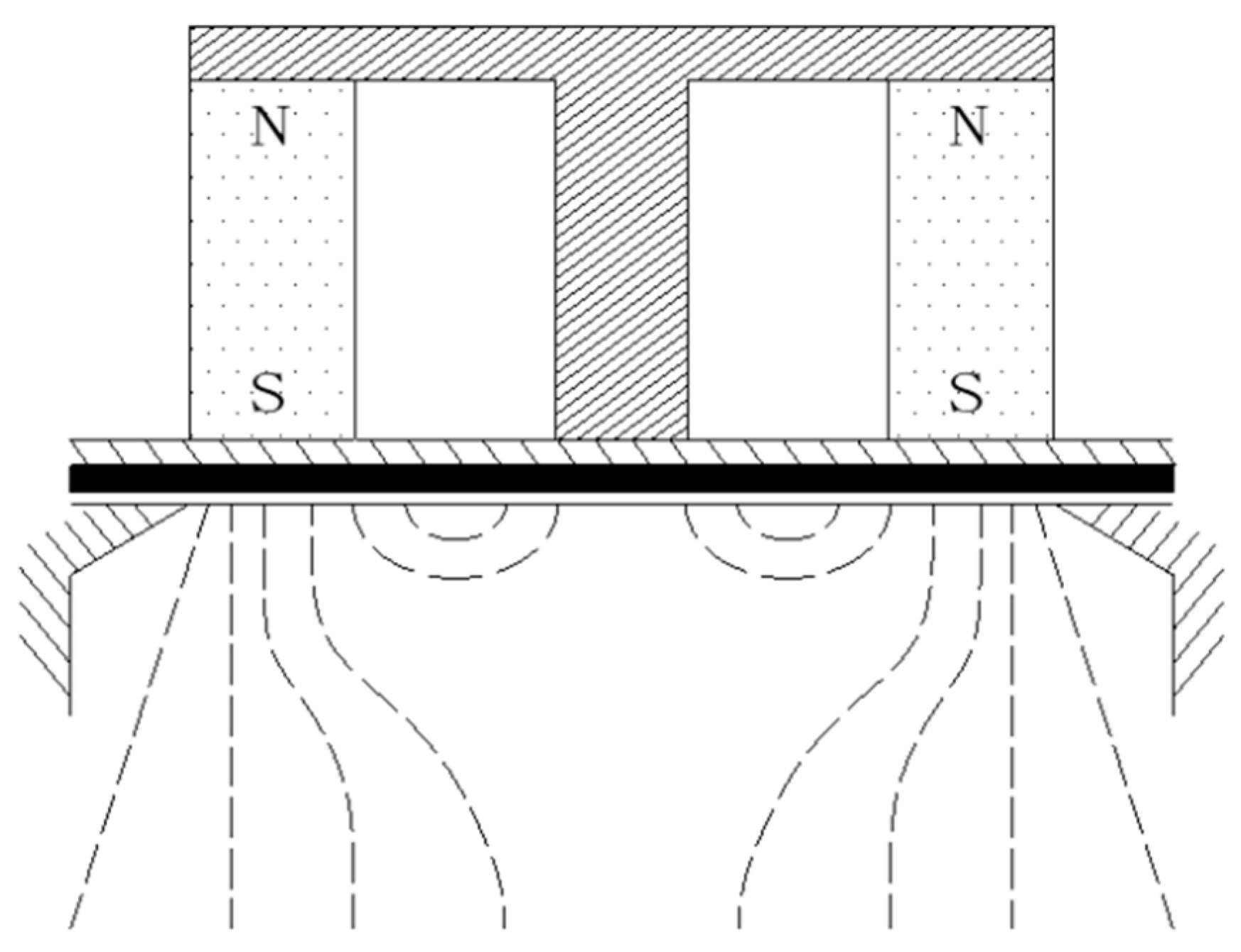
The UBMS working principle is shown in
Figure 2. It enhances the magnetic field of the N pole on both sides or weakens the magnetic field of the intermediate S pole such that the S pole and N pole form a transverse magnetic field on the surface of the target to ensure that the secondary electrons deposited can be effectively constrained and stably discharged by changing the distribution of magnetic fields via balanced magnetron sputtering. Further, the other part of the electrons escapes from the target surface through the longitudinal magnetic field of the N pole and enters the coating area [
30].
After the preparation of the orbiting scroll specimens, the grease and residual dirt on the surface of the orbiting scroll was removed to make the film layer easier to fit the substrate material. The acetone and the ethanol were used as the cleaning medium in ultrasonic cleaning machine to remove remaining impurities on the metal surface. Then, in this unbalanced closed magnetic field magnetron sputtering surface treatment progress, the glow discharge cleaning method was applied to remove the carbon and hydrocarbon impurities. The cleaning process was filled with appropriate inert gas argon, and the working pressure was adjusted to 10 Pa. After dehydration and the drying progress, the specimen was put into a vacuum chamber (0.0027 Pa). Next, the fiber laser marking machine was used to generate ionization power to heat and etch the surface of the sample to increase the bonding force between the film and the surface of the sample. Finally, the Cr transition layer was coated on the substrate surface to enhance the bonding force, and then the DLC film was coated on the Cr layer through opening the magnetron target successively (coating time 75 min).
2.2. Characteristic Parameters Testing of the DLC Film
2.2.1. Wearing Coefficient
The friction and wearing experiments are critical for the analysis of friction performance of solid surface. Two samples and a ball of 5 mm diameter made of Al2O3 were rubbed for 10 thousand revolutions under certain loads to measure the change of the wearing coefficient on the friction testing machine.
2.2.2. Thickness
There are usually three ways to express the film thickness: shape thickness, mass thickness, physical thickness. The thickness here refers to the shape thickness, that is, the distance between the substrate surface and the film surface. In practical measurement, the surface of the film is rough, and there are many impurities in it. An appropriate measurement method should be selected to characterize the thickness of the film. The thickness of the anodic oxide film in this experiment was measured by indirect measurement method with the spherical pit thickness measuring instrument. The thickness of the DLC film was measured by direct measurement using a scanning electron microscope (SEM).
2.2.3. Microhardness
The hardness of the orbiting scroll is not only closely related to its service life but also the efficiency of compressors, so it is one of the most important parameters to evaluate the quality of the orbiting scroll. A microhardness tester (Vickers indenter) was used to test the hardness of the material. In order to avoid the deformation of the body in the testing process, an appropriate load should be used. In this testing experiment, the MH-VK (Microhardness-Vickers and Knuckle indenter) microhardness test system was used to measure the microhardness. We put 50 g loads on the surfaces of the two samples, respectively, with Vickers indenter and measured the diagonal length of indentations after loading, holding, and unloading to calculate the microhardness of samples.
2.2.4. Film–Substrate Adhesion
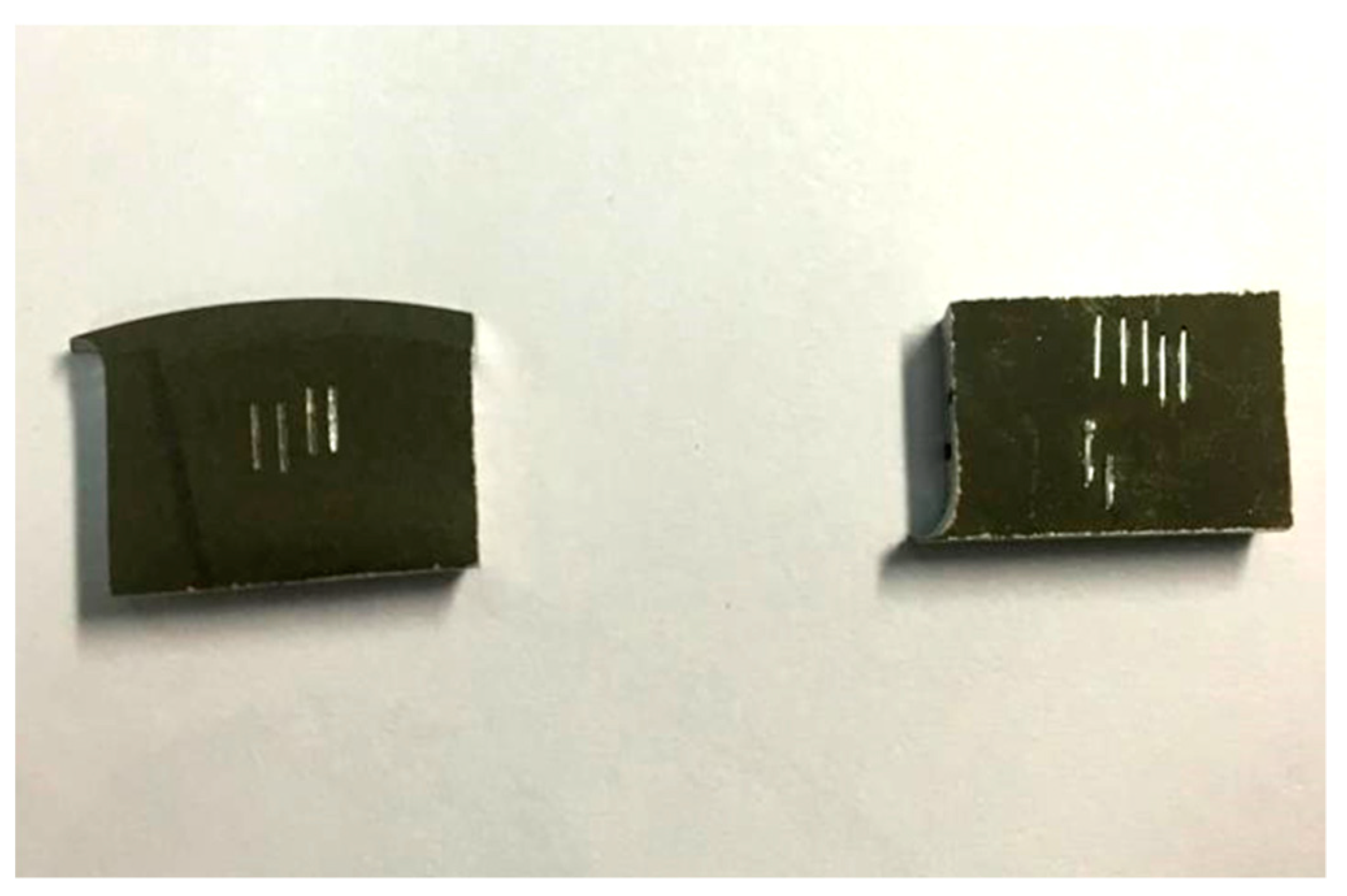
The film–substrate adhesion refers to the external force required to peel the film from the substrate, which indicates the bonding strength between the film and the substrate. In general, the smaller the difference in the physical and chemical properties between the film and the substrate, the higher the adhesion. Besides, the adhesion is also affected by the factors such as the preparation process, the transition layer, and the film composition. In this paper, the film-substrate adhesion of the anodic oxide film and the DLC film was measured by scratch method which is a quantitative measuring method. First, we used the scratch instrument to leave scratch marks with different loads on the surfaces of the two samples, as shown in
Figure 3. In this figure, the left one is the sample coated with the anodic oxide film and the right one with the DLC film. The loads on the surface of the anodic oxide film from left to right are 60 N, 70 N, 80 N, and 90 N, respectively, and on the surface with the DLC film from left to right are 40 N, 60 N, 70 N, 80 N, and 90 N. Then the peeling point of the film substrate was found under the scanning electron microscope.
2.2.5. Surface Morphology
At present, the most common tool to study the surface morphology of materials is the scanning electron microscope (SEM). It can provide surface morphology images clearly and intuitively and give quantitative or semi-quantitative surface composition analysis results. The principle of scanning electron microscopy is that the surface of the sample is bombarded with a very narrow electron beam to motivate signals, such as the secondary electrons and transmitted electrons on the surface of the sample, which can be analyzed to observe the surface morphology of the sample. The resolution ratio of SEM can reach 5–10 nm, and the magnification times can be adjusted from several times to 1 million times.
2.2.6. Composition Structure
X-ray diffraction (XRD) is usually used to detect the structure and composition of the film surface and determine the crystal plane of solid surface. If the surface crystal composition of the two materials is different, their XRD spectrogram will show obvious differences in angle position, diffraction peak number, and shape. Therefore, the phase composition of the sample can be determined by analyzing the X-ray diffraction pattern on the surface of the experimental sample. For amorphous substances on the surface, because of the irregular arrangement of atoms in space, there will be no obvious diffraction peak in the diffraction spectrum. Therefore, the phase composition of samples was analyzed by the D/max-3A X-ray diffraction instrument.
2.3. Performance Parameters Measuring of the Scroll Compressor
In order to compare and analyze the performance of DLC film in the scroll compressor, a performance experiment was carried out. This performance test bench for automobile air-conditioning compressors was based on the GB/T 5773-2016 Volumetric Refrigerant Compressor Performance Test Method. The test bench was debugged according to the standard operating conditions in GB/T 21360-2008 Refrigeration Compressors for Automobile Air-Conditioning to ensure the accuracy of the compressor performance test.
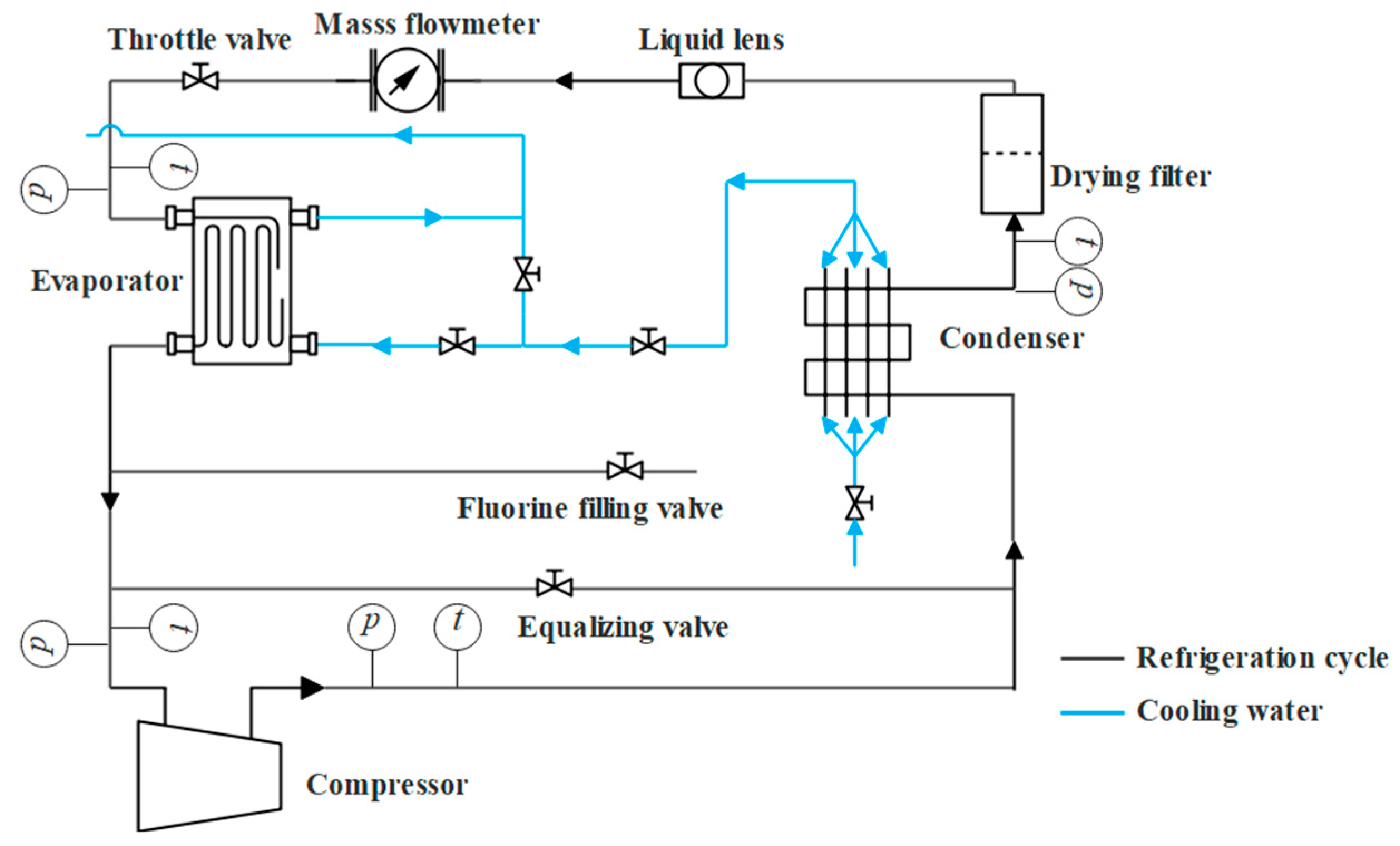
The principle of this experiment is close to a simple automobile refrigeration and air conditioning system.
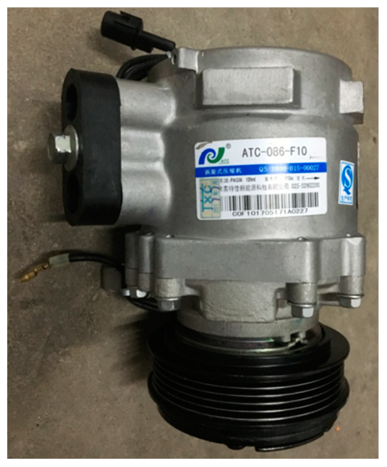
Figure 4 is the schematic diagram of experimental progresses. The refrigerant is R134a. The evaporator and condenser in this experiment all use plate heat exchangers. As an ideal equipment for high-efficiency heat exchange, the plate heat exchanger has two forms: assembled and brazed. The evaporator and condenser used in the experiment are all brazed. The compressors used in the experiment are two scroll refrigeration compressors for fully enclosed cars, the model is ATC-086-F10, and the driving mode is pulley. The basic parameters of the compressors are shown in
Table 1.
Figure 5 shows the real scroll compressor used in experiments.
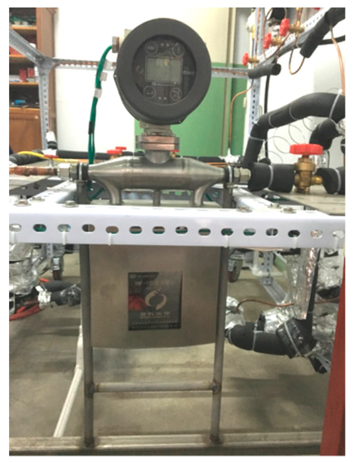
Due to the large resistance of the plate heat exchanger, if an internally balanced thermal expansion valve is used, it will affect the accuracy of the superheat. Therefore, this experiment used an externally balanced thermal expansion valve. As the tube diameter of the mass flow meter was small and easy to be blocked, the filter drier was installed before the mass flow meter to remove mechanical impurities (such as metal chips and oxide scale) in the refrigerant and to adsorb moisture in the refrigerant. We installed a sight glass before the flow meter to observe whether there was a gaseous working fluid. Plus, this experiment uses the refrigerant liquid flowmeter method, and the flowmeter is a Coriolis mass flowmeter, as shown in
Figure 6. The temperature measurement uses a Pt100 thermal resistance temperature sensor with an accuracy of class A, and the temperature measurement range is −50–200 °C, which meets the requirements of use. The temperature of each measuring point is collected in real time with a temperature inspection instrument, and the measurement error is ±0.5% FS (Full Scale) ± 1 word, and the additional cold junction compensation error is ±1 °C. The accuracy of the suction pressure gauge is 0.4, and the range is 0 to 1.6 MPa. The discharge pressure gauge accuracy is 1.6, the range is 0 to 4 MPa, and it is resistant to high temperature and vibration. The refrigerant charge amount is determined according to the actual operating conditions, and its value is obtained through the reading of the electronic scale, and the scale value of the electronic scale is 1 g.
The condensation pressure and the degree of subcooling were adjusted by the cooling water flow rate whose temperature was 16 °C. The evaporation temperature (or pressure) is adjusted by the heat exchange on the evaporation side. The evaporation temperature is adjusted by adjusting the water flow on the evaporation side. The superheat at the outlet of the evaporator is adjusted by the thermal expansion valve. The condensing temperature (or pressure) and the degree of subcooling are adjusted by the heat exchange on the condensing side. In the experiment, the condensing pressure is adjusted by adjusting the water flow on the condensing side. Since the filling of refrigerant and the oil volume in the system can influence experimental results, the optimal values are 1210 g and 217.8 g, respectively, after repeated debugging. The data of performance experiment were recorded after keeping steady for more than 0.5 h. The refrigeration capacity was tested according to the refrigerant liquid flow meter method, and the power was collected by a digital electric parameter measuring instrument. After that, we debugged and collected data on the experimental test bench under standard working conditions, then processed and analyzed the collected data. The experimental working conditions are shown in
Table 2 and
Table 3.
3. Results and Discussion
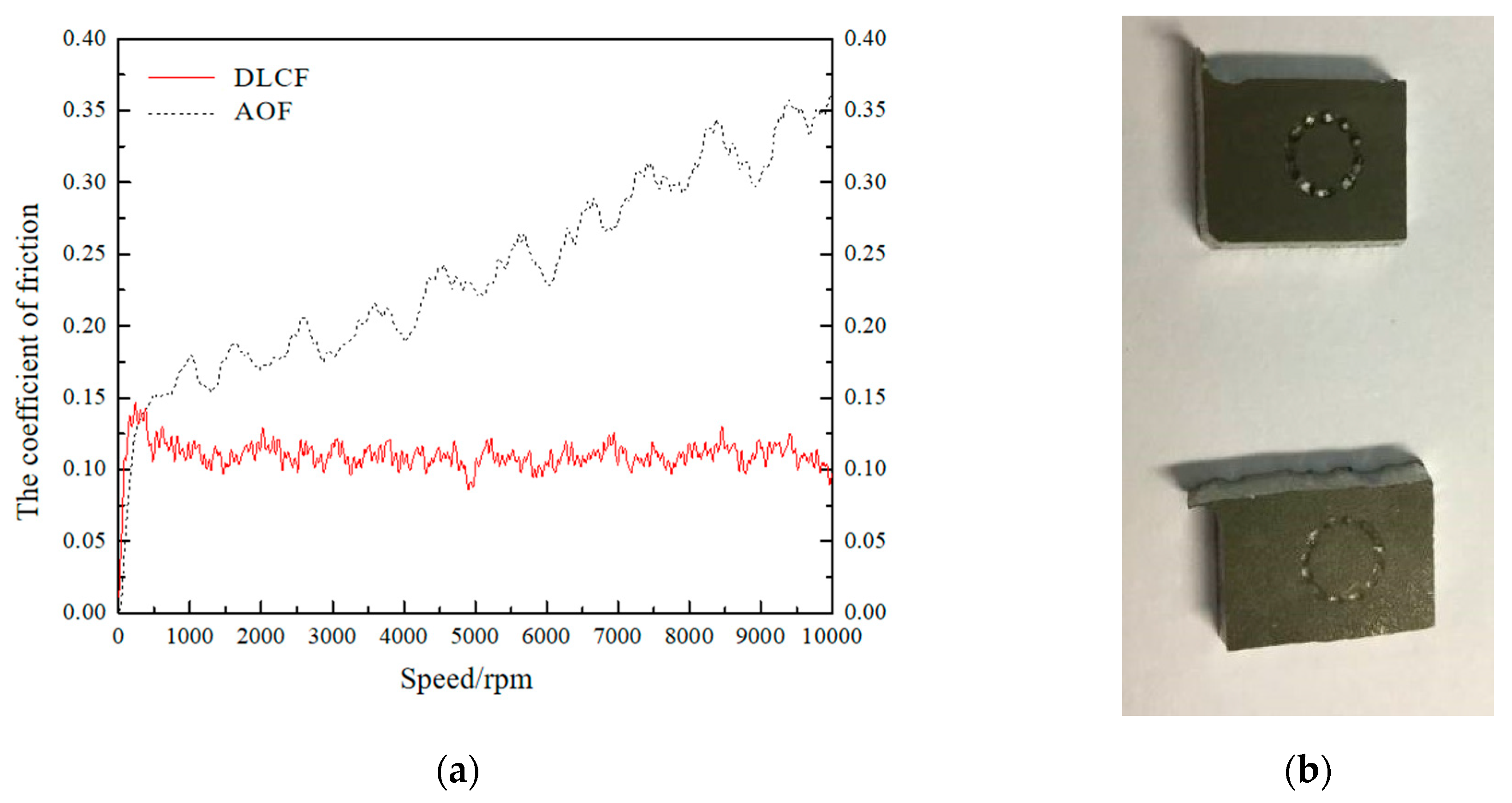
Figure 7 shows friction coefficient curves and test samples. At the initial stage of wear, the friction coefficient of the two samples increases rapidly because the Al
2O
3 ball is polished by the surface of the samples. The friction coefficient of the sample coated with DLC film is gradually stabilized after 10,000 rotations but with the anodic oxide film it is not, showing an increasing trend. The friction coefficient with the anodic oxide film is much larger than that with the DLC film. As shown in
Figure 7b, the surface of the sample with the anodic oxide film has a chip-grinding phenomenon. The surface scratch of the sample with the DLC film is relatively shallow and smooth. It proves that the DLC film has a good wear-reducing effect and an excellent self-lubricating property.
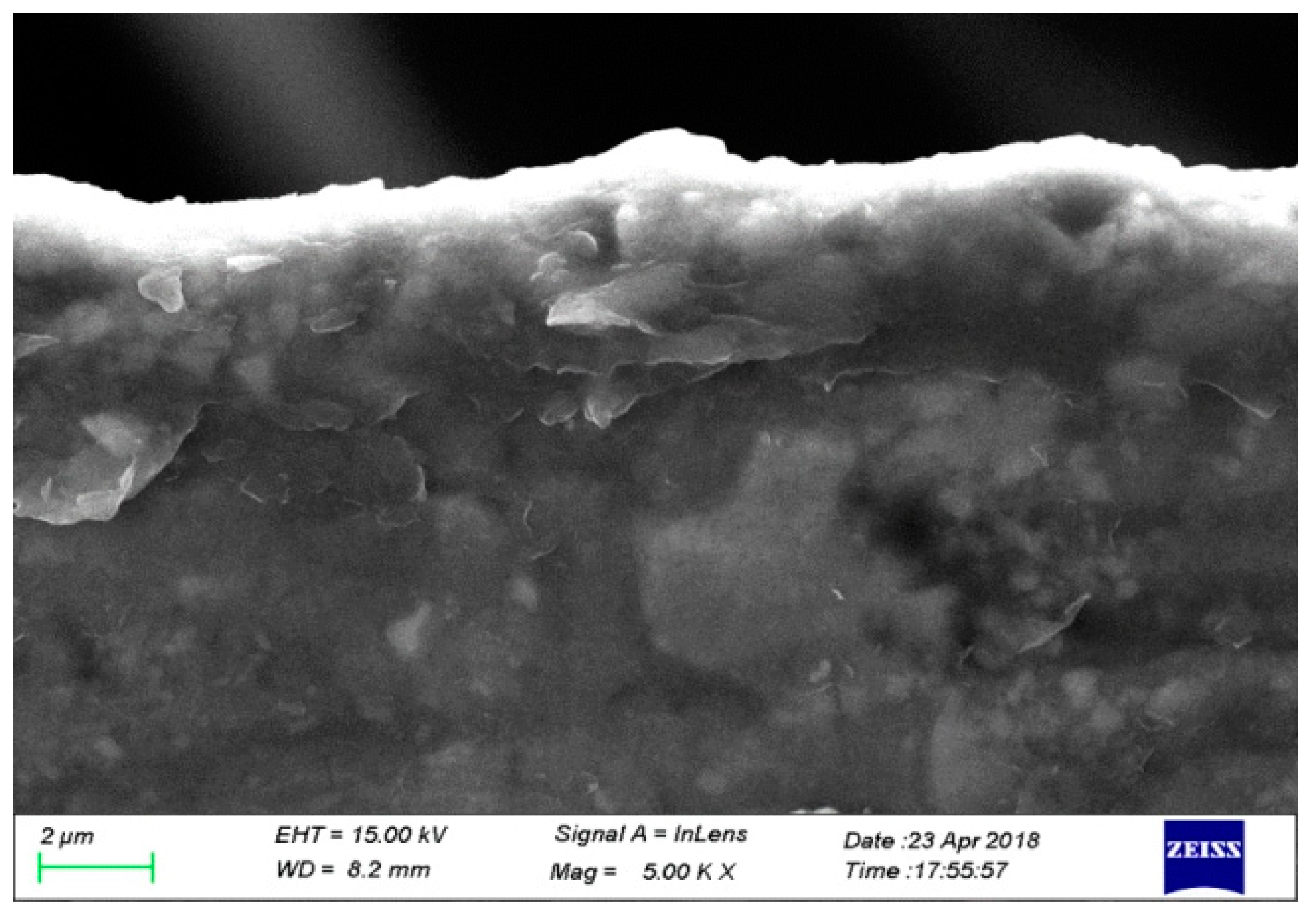
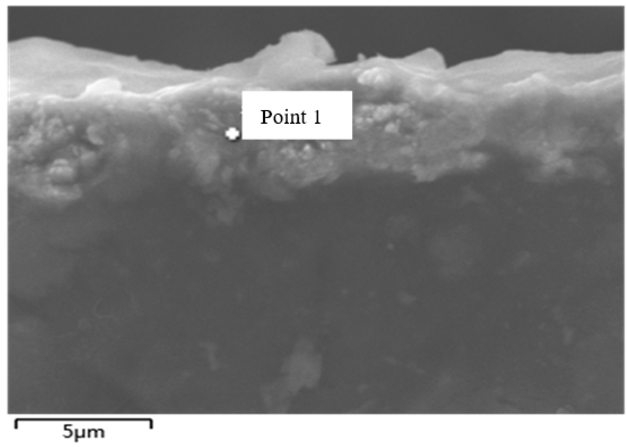
The thicknesses of anodic oxide film and DLC film are 4 μm and 0.73 μm, respectively, which means the DLC film is better than the anodic oxide film.
Figure 8 shows the section topography of the DLC film. The hardness of the anodic oxide film and DLC film are 254.1 HV and 206.7 HV, respectively. The Vickers hardness of the sample with DLC film is lower than that with anodic oxide film. The thickness and the hardness are not related directly. The main reason why the hardness is lower is that there are fewer SP
3 bonds and more SP
2 bonds, which makes the DLC film have a property close to graphite. Furthermore, the hardness of DLC film is related to the working temperature. When the working temperature is increased, the hardness will be decreased.
Figure 9a,b shows the surface of anodic oxide film under 60 N loads and the DLC film under 90 N loads, respectively. As can be seen from
Figure 9, the anodic oxide film is peeling off when the load is 60 N, but no peeling point is found on the surface of the DLC film when the load is 90 N, which proves that the bonding strength of the DLC film is much higher than that of the anodic oxide film.
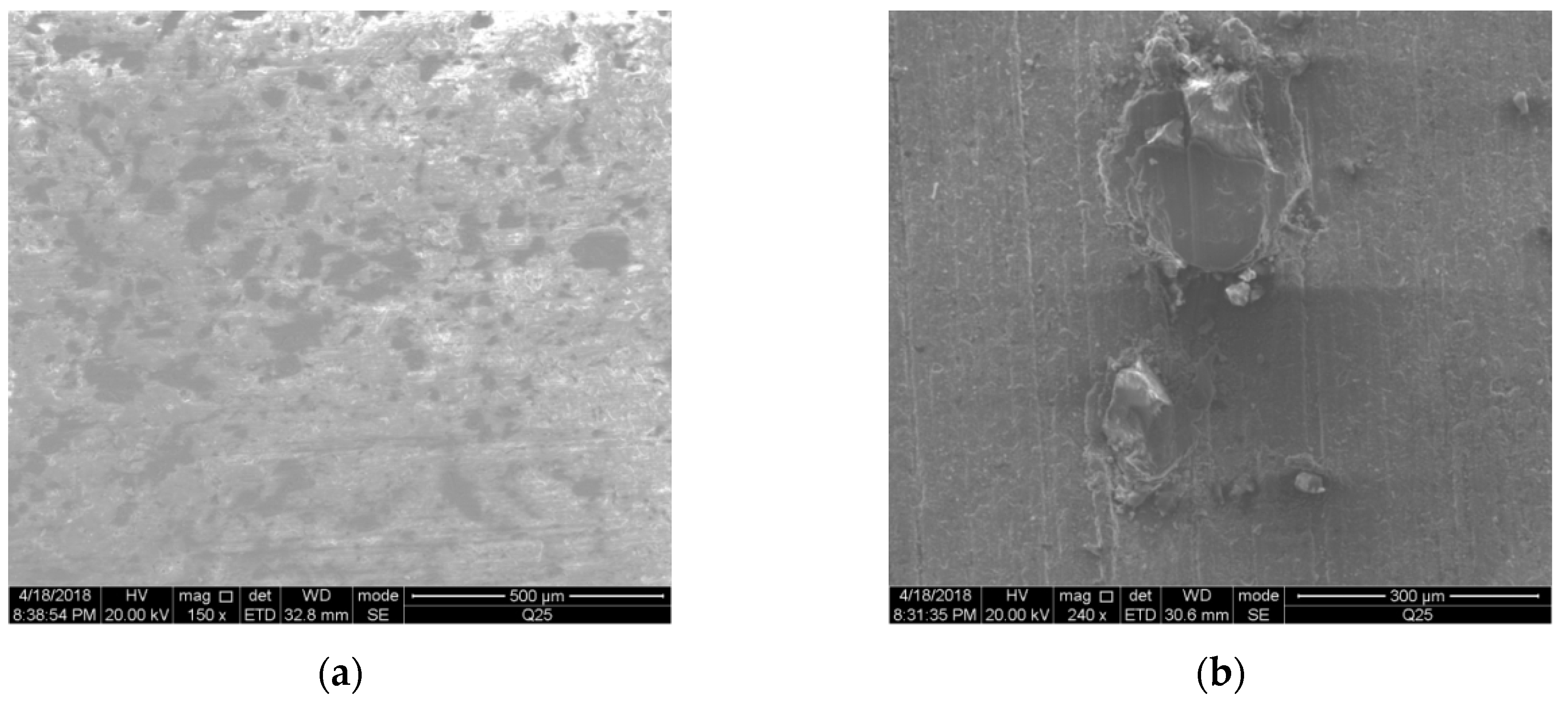
Figure 10 and
Figure 11 show the surface morphology with the SEM. Although the surface of the anodic oxide film (AOF) has been treated, the surface smoothness is poor and there are many pores. These defects could result in a poor film–substrate adhesion and high friction coefficient of the anodic oxide film. However, the surface of the sample coated with DLC film is flat and smooth. The crystalline grain of the DLC film is uniformly and compactly distributed on the surface of the sample with good coating quality, which eliminates the surface defects of the orbiting scroll. In addition, there are no obvious bubbles around the crystalline grain, which ensures the bonding strength between the DLC film and the sample body.
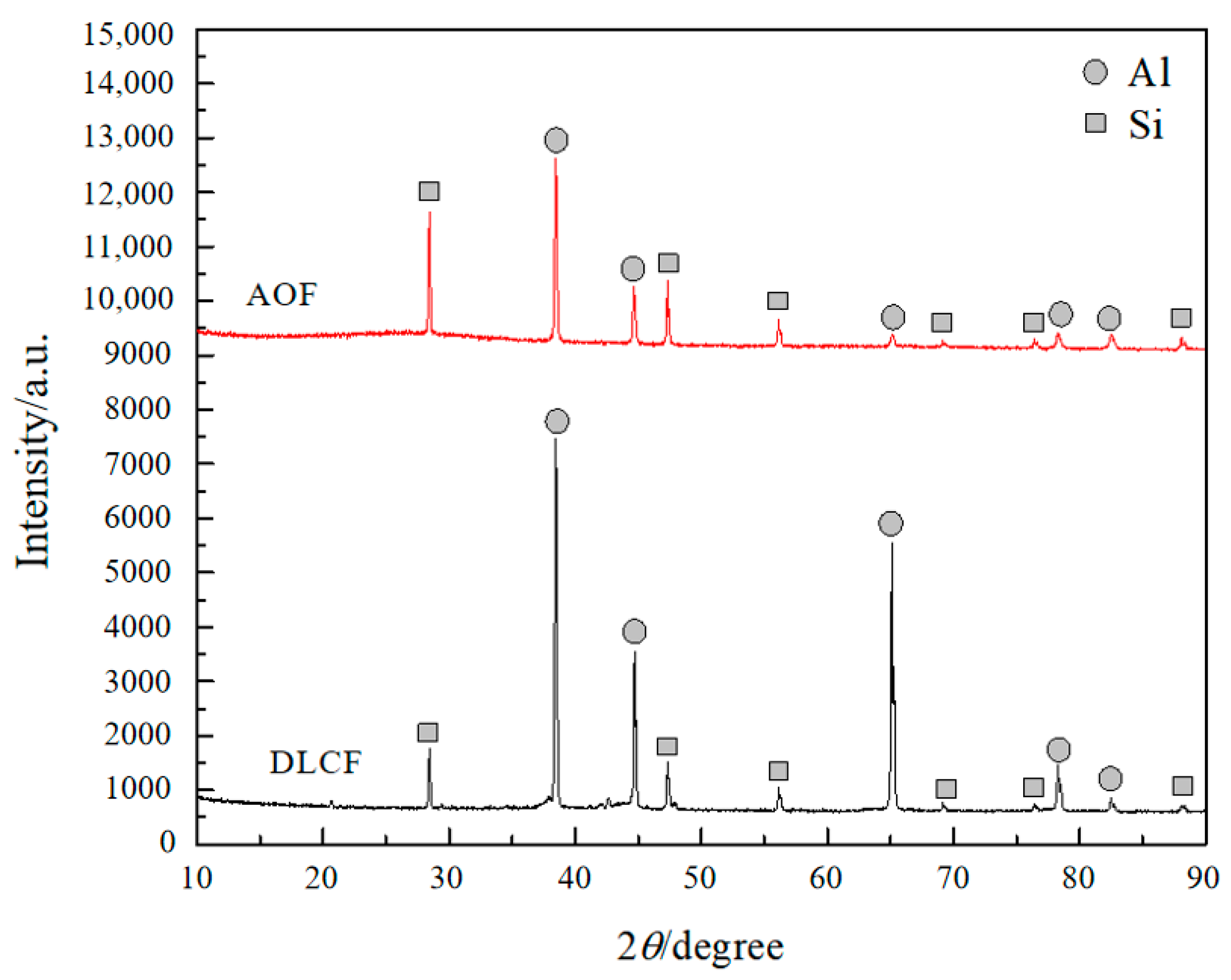
The X-ray diffraction spectrum of the anodic oxide film and the DLC film is shown in
Figure 12. It shows that there is no significant difference in the XRD spectrum between the anodic oxide film surface and the DLC film surface. The DLC film is mainly characterized by the diffraction peak of the substrate. Under the usual diffraction conditions, the penetration depth is about dozens of microns, while the thickness of the anodic oxide film is only 0.73 μm in amorphous state, resulting in no carbon diffraction peak. In order to further analyze the composition of the films, the surface composition and content of the two samples were analyzed by energy dispersive spectrometer (EDS).
Table 4 shows the surface element content and percentage of DLC film. The results show that the carbon content in the DLC film is very low (only 5.90%), and the Cr content is much higher (26.17%). This is because the film layer of the DLC film is thin, and the results detected by EDS mainly are the element content and percentage of the substrate. In order to further analyze whether there are carbon elements on the surface of the DLC film, the energy spectrum analysis of the DLC film section was carried out (
Figure 13). The carbon content maximum value is relatively high (about 54.92%). Based on the previous analysis, the surface substance composition of the DLC film can be determined to be carbon and chromium. Moreover, it is verified that the reason why the micro Vickers hardness of the DLC film is lower than that of the anodic oxide film is fewer SP
3 bonds and more SP
2 bonds, which makes the property of the DLC film close to graphite.
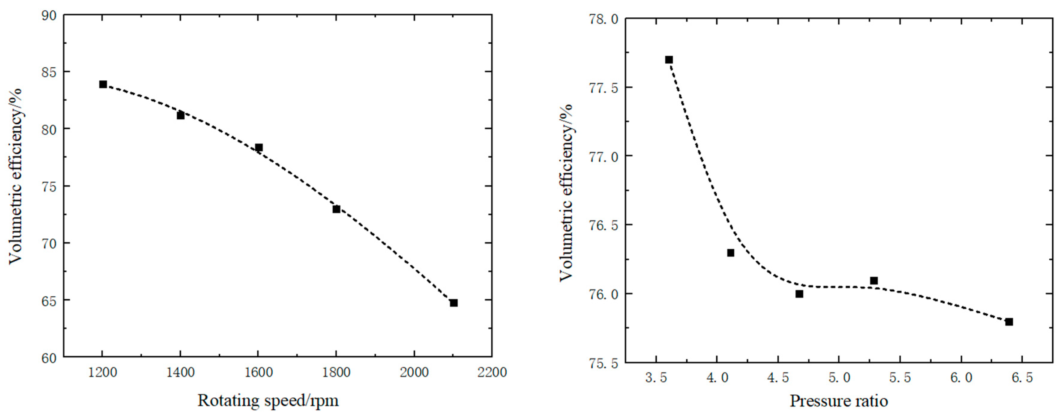
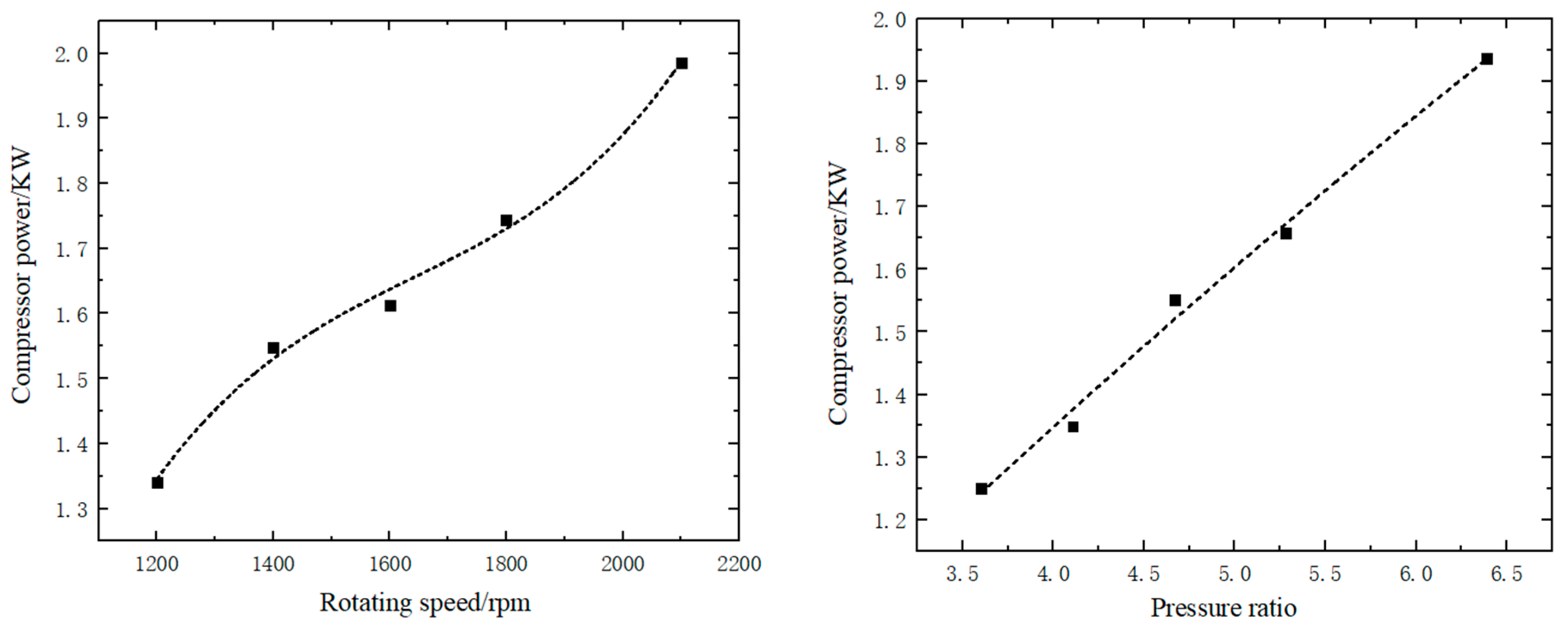
Volumetric efficiency and power consumption are effective parameters to evaluate the compressor performance (
Figure 14 and
Figure 15). It can be noticed that the power of the scroll compressor coated with DLC film increases by 13.6% with the rotating speed increasing by 200 rpm and 14.0% with the pressure ratio increasing by an average 0.56. The volumetric efficiency decreases by 0.0382 with the rotating speed increasing by 200 rpm and 0.00377 with the pressure ratio increasing by an average 0.56. That is because that the thickness of DLC film is too thin to make the internal leakage of the compressor increase and the volumetric efficiency decrease. It means that the thickness of 0.73 μm should be increased. Many research studies show that the thickness should be in the range 2.5–5 μm. As they said, if the thickness is too low, the wear life will drop sharply. When the rotating speed is high, the leakage and wear cannot be ensured to make the machine run normally. If the thickness is too high, the intake and discharge space will be affected, and energy consumption will increase. Whether this phenomenon occurs in the same way in scroll compressors remains to be studied. In addition, because the Vickers hardness of DLC film is lowered by this UBMS technology, the wear of the orbiting scroll is more serious, which makes the power consumption of the compressor and internal leakage increase. It is a key research point for future adjustments and improvements.
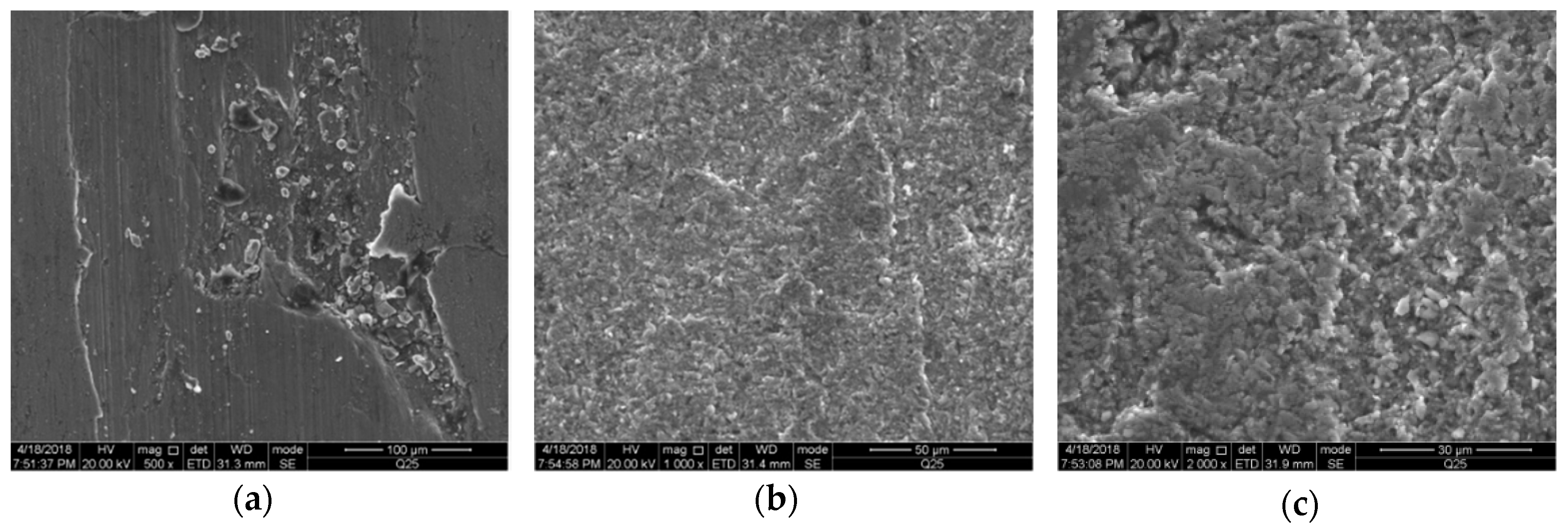
After operating through the experiments, we tested the properties of the DLC film again. There are corresponding scratches and wear on the surface of the compressor scroll, especially the suction and discharge ends. The scratches on the surface of the scroll are due to impurities mixed in the system. Therefore, samples were taken at the suction and discharge ends of the compressor, and the surface morphology of the samples was observed through an electron microscope.
The test results are shown in the
Figure 16 and
Figure 17. It can be found that the surface of the orbiting scroll has fatigue wear mainly due to delamination. Since the discharge end is the area where the scroll is most stressed and thermally deformed, the friction and wear are the most serious. Therefore, combined with the surface morphology of the scroll after operation, it can be concluded that the reason why the performance of the compressor is good at low speeds is the flat surface of the DLC film and low friction coefficient, which reduces the flow-resistance loss of the working fluid. When the speed is high, the main reason for its performance degradation is that under a high rotation speed, the low hardness and thickness of the orbiting scroll results in increased wear and obvious internal leakage.
4. Conclusions
In this paper, we mainly studied the film coating technology of the DLC film for the orbiting scroll of scroll compressors in an automobile air conditioning system to reduce its friction coefficient and improve film–substrate adhesion, wear resistance, and performance of the compressor. Considering that the material of the orbiting scroll is aluminum alloy, we proposed the unbalanced magnetron sputter technology to coat the DLC film on the surface of the orbiting scroll, analyzed the properties of the DLC film, compared the properties of the DLC film with those of the anodic oxide film as controls for the scroll compressor, and designed performance experiments to verify the reliability and feasibility of the unbalanced magnetron sputter film coating technology in scroll compressors.
The friction coefficient with the DLC film is much smaller than that with the anodic oxide film, which makes the DLC film have a good wear-reducing effect and an excellent self-lubricating property. The thickness of the anodic oxide film and the DLC film is 4 μm and 0.73 μm, respectively. The Vickers hardness of the sample with the DLC film is lower than that with the anodic oxide film, and the bonding strength of the DLC film is much higher than that of the anodic oxide film. The surface of the sample coated with DLC film is flat and smooth, which eliminates the surface defects of the orbiting scroll. The surface substance composition of the DLC film was determined to be carbon and chromium. It is also verified that the reason why the micro Vickers hardness of the DLC film is lower than that of the anodic oxide film is fewer SP3 bonds and more SP2 bonds, which makes the property of the DLC film close to graphite. The refrigeration system with the scroll compressors coated with the DLC film can meet the national standards, indicating the surface treatment technology is suitable and appropriate. The DLC film can improve the film–substrate adhesion, wear resistance, and the performance of the compressor. The unbalanced magnetron sputter technology and increasing Cr bond layer are feasible and appropriate for coating DLC film on the orbiting scroll of scroll compressors. Furthermore, through the performance experiments, the power of the scroll compressor coated with DLC film increases and the volumetric efficiency decreases with the rotating speed and pressure ratio increasing. The thickness of DLC film should be increased to 3–4 μm. Finally, the Vickers hardness of DLC film is lowered by this UBMS technology, which is a key development direction for future research.
The optimized scheme of the unbalanced magnetron sputtering technology proposed in this paper to prepare DLC film on the surface of aluminum alloy to improve the wear resistance of the scroll, not only reduces the friction coefficient of the scroll surface, but also improves the bonding force of the film base, which can effectively solve the problem of large friction loss of the scroll compressor. Scroll compressors have been widely used in a variety of refrigeration applications. As the largest energy-consuming component in the system, the ability to use this more energy-saving, environmentally friendly, low cost, safe and reliable method to solve key problems will undoubtedly lead to the further expansion of the material industry and machinery industry. The idea of this solution can not only be applied to scroll compressors but can be applied to power machinery such as hydrogen pumps based on the experimental data parameters, because, at present, in addition to fuel vehicles, fuel cell electric vehicles are also research hotspots and key development projects. The solution can reduce mechanical burden in the automotive industry with higher safety requirements and is one of the technical solutions that are worthy of reference. In the meantime, the experimental data can be used as the training database for compressor fault diagnosis.
