Review

Novel Diagnostic Techniques for Rotating Electrical Machines—A Review †

Department of Electrical, Computer and Biomedical Engineering, University of Pavia, Via Ferrata 5, 27100 Pavia, Italy
This paper is an extended version of my paper published in the 2019 IEEE Workshop on Electrical Machines Design, Control and Diagnosis (WEMDCD), Athens, Greece, 22–23 April 2019.
Energies 2020, 13(19), 5066; https://doi.org/10.3390/en13195066
Submission received: 29 August 2020 / Revised: 16 September 2020 / Accepted: 25 September 2020 / Published: 27 September 2020
(This article belongs to the Special Issue Condition Monitoring and Diagnosis of Electrical Machines)

Abstract

:
This paper aims to update the review of diagnostic techniques for rotating electrical machines of different type and size. Each of the main sections of the paper is focused on a specific component of the machine (stator and rotor windings, magnets, bearings, airgap, load and auxiliaries, stator and rotor laminated core) and divided into subsections when the characteristics of the component are different according to the type or size of the machine. The review considers both the techniques currently applied on field for the diagnostics of the electrical machines and the novel methodologies recently proposed by the researchers in the literature.

1. Introduction

Recently, diagnostic techniques for the condition monitoring of rotating electrical machines have experienced an extraordinary growth and development, as can be observed in the increased number and quality of papers on this topic published in scientific journals, in their special issues and in related conferences of recent years, e.g., Symposium on Diagnostics for Electric Machines, Power Electronics and Drives (SDEMPED), Workshop on Electrical Machines Design, Control and Diagnosis (WEMDCD), International Conference on Electrical Machines (ICEM), etc. This happened for several reasons. First of all, predictive maintenance is increasingly widespread in the industrial sector and in many other fields, such as electric traction, and this strategy requires the use of advanced diagnostic techniques, possibly non-intrusive and on-line. Secondly, the world is becoming more and more electric [1] and therefore electrical machines are progressively more present in any application. Lastly, the sensors needed to measure the quantities to be monitored to predict the condition of the machines are now more reliable, miniaturized and cheaper than in the past, thanks to the progress in electronic and computer engineering, and are consequently easily applicable not only to large power machines, but also to those of small and medium power.
A further evolution of diagnostics (or diagnosis) is prognostics (or prognosis); diagnostics consist in identifying the fault that will lead to a failure and estimating its severity, while prognostics rely on continuous monitoring of the variables and parameters of the system and use this information to predict the time until a failure occurs, known as remaining useful life (RUL) [2]. In other words, prognostics aim to forecast the evolution of a fault and to predict when the machine will no longer operate as designed or desired [3]. Prognostics may be used to evaluate the rate of degradation and may permit the machine to continue to operate regularly until the moment of failure; it may diminish unnecessary expensive maintenance and unexpected failures [4].
Due to the huge amount of papers on both diagnostics and prognostics and their applications to engineering systems, e.g., [3,4,5,6,7], this review focuses on the first theme, with application to rotating electrical machines, therefore excluding mechanical systems, such as gas turbines and engines. Electrical machines obviously include those supplied by electronic converters, but the faults analyzed in this paper do not comprise those that occur in electronic devices.
In recent literature, there are some excellent reviews on diagnostics of electrical machines, published in journals five and six years ago [8,9,10]. Furthermore, a very interesting review was published in the proceedings of a conference last year, but it is limited to the use of the stray flux analysis as a diagnostic technique [11]. As research in this field has recently grown exponentially, this paper aims to update the state of the art, adding the most significant outcomes reported in the literature of the last five years. Unlike previous reviews, this paper is structured with two first sections (the second and the third) that report broad-spectrum considerations on diagnostics of electrical machines, coming from an overall evaluation of the literature on this topic and from the author’s experience. Each of the following seven sections (from Section 4 to Section 10) is dedicated to one of the main components of the machines prone to fault, as graphically shown in Figure 1; in each of these sections, the techniques appropriate to all major types of electrical machines are reviewed, with particular attention to the problems arising from the supply of the machines through electronic converters.

2. The Targets of Diagnostics

Diagnostics are the procedure for translating information deriving from the measurement of parameters relating to a machine into information concerning actual or incipient faults of the machine itself. In other words, diagnostics are the complex of analysis and synthesis activities which—using the acquisition of some physical quantities, characteristic of the monitored machine—allows for collecting significant information on the condition of the machine and on its trend over time, for evaluation of its short- and long-term reliability.
The targets of the diagnostics are: (i) detection (whether the fault is present or not); (ii) isolation (in which part of the machine); (iii) identification (which kind of fault). The general problem of diagnostics is to detect whether or not a specific fault is present based on the available information, preferably without an intrusive inspection of the machine [12]. This problem can be described with a statistical approach as a hypothesis-testing problem: the null hypothesis H0 affirms that the fault is present and the alternative hypothesis H1 asserts that the fault is not present. Hypothesis testing is subject to two types of error. A type I error occurs when the null hypothesis H0 is true and it is rejected, i.e., when, on the basis of the available information, it is decided that the fault is not present, but really it is. Therefore, the machine is not stopped and repaired before the actual manifestation of the failure, with possible catastrophic consequences. A type II error occurs when the null hypothesis is false and one fails to reject it, i.e., when it is decided that the fault is present, but in reality it is not. Then, the machine is stopped and repaired in vain, with useless economic costs.
A diagnostic program is developed according to the following steps: (i) data acquisition; (ii) data processing; (iii) decision-making. The methods employed for data acquisition and processing and for choosing the threshold which separates the faulty condition from the healthy condition of a component can heavily influence the probability of committing an error during the decision-making phase. The term “fault detection” generally refers to a decision made by an individual, while the term “diagnosis” or “diagnostics” usually refers to a decision given by an automatic algorithm.
If the object of diagnostics is a rotating electrical machine, its operation cannot be considered separately from: the operation of the mechanical machine connected along its axis line (pump, fan or other load for an electrical motor; turbine or other prime mover for an electrical generator); the type of the mechanical coupling (joint, gears, belts, etc.); the possible control system (inverter, etc.). All these mechanical and electronic systems can: induce faults in the electrical machine; arouse variations in the parameters of the electrical machine, even in the absence of a fault; suffer faults induced by the electrical machine.
For these reasons, it is important to separate the following situations: (i) a rotating electrical machine directly connected to the grid; (ii) a rotating electrical machine connected to the drive in open loop; (iii) a rotating electrical machine with closed-loop control.

3. Diagnostics of Rotating Electrical Machines

The main types of rotating electrical machines include: induction machine (IM) with a squirrel cage rotor (SCIM) or wound rotor (WRIM); synchronous machine (SM) with salient poles or a wound cylindrical rotor; permanent magnet synchronous machine (PMSM); synchronous reluctance machine (SynRM); switched reluctance machine (SRM); brush DC machine (BDCM). There are many variants of these machines, which can be realized as: single-phase, three-phase or multi-phase; with radial or axial flux; connected directly online (DOL) to the grid or driven by an electronic converter. Further variants comprise: doubly fed induction machine (DFIM), brushless doubly fed induction machine (BDFIM). Each variant determines peculiar features in the behavior of the machine and in its condition monitoring.
Faults can occur in the following components: (i) stator winding; (ii) rotor winding; (iii) magnets; (iv) bearings; (v) airgap; (vi) load and auxiliaries; (vii) stator and rotor laminated core; (viii) other components (commutator, collector rings, slip rings, etc.) [13].
Diagnostic methods can be founded in the analysis of electromagnetic, mechanical and other parameters: vibration, current, external stray flux, internal airgap flux, voltage, electric power (instantaneous, active, reactive), temperature (also with infrared thermography), partial discharges and acoustic noise. Some quantities, such as current, can be measured in steady state or during the starting transient. The methods to analyze the current in steady state are mainly divided into motor current signature analysis (MCSA) and negative sequence (Park current).
Vibration measurement by means of transducers positioned on the bearings is generally employed for the detection of mechanical faults, such as bearing defects, mechanical imbalance (even due to the load) and malfunctions in the transmission system. However, an anomalous vibration can also be a symptom of electrical faults, since any electrical fault produces an asymmetry in the distribution of the magnetic flux at the airgap. In turn, this asymmetry produces an asymmetrical distribution of the electromagnetic forces inside the electrical machine, which affects its vibrations. For this reason, the vibration measured in the casing and in the end-windings can help in the detection of electrical faults, such as non-uniform airgap (static or dynamic eccentricity), faults in stator or rotor windings and imbalance in the power supply.
On the other hand, electromagnetic signals can help in the detection of mechanical faults, since most mechanical faults produce a radial displacement between rotor and stator and this displacement produces an asymmetry in the magnetic flux at the airgap. In turn, this asymmetry affects the inductances of the machine which determine harmonics in the stator current and in the stray magnetic flux. Therefore, not only does the primary effect of each fault need to be evaluated as a possible diagnostic indicator, but even its secondary effect.
In recent years, traditional diagnostic techniques, based on the vibration measurement, have been progressively abandoned in favor of the analysis of electromagnetic signals, in particular the stator current and the external stray flux around the motor [11]. The aim is to use fewer sensors, possibly already existing in the electrical drive for machine control.

Diagnostics of Electrical Motors Fed by Electronic Converter
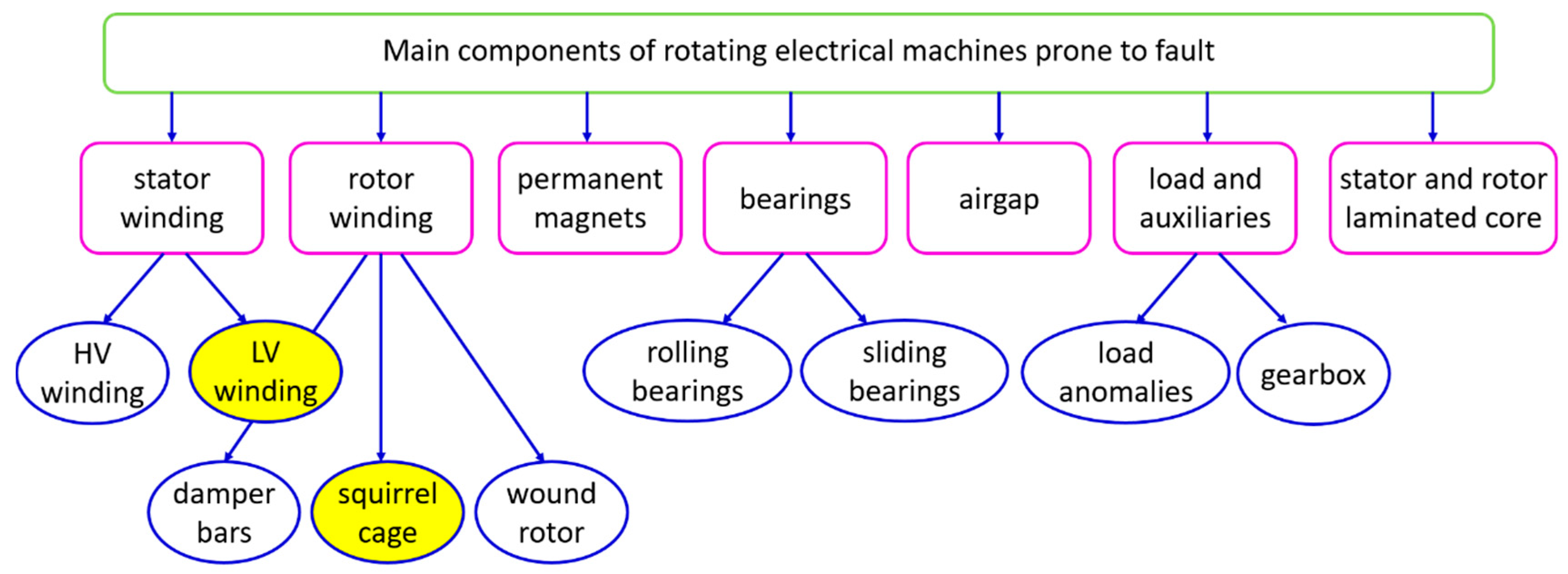
Generally, diagnostics through the measurement of electromagnetic signals are heavily influenced by the power supply of the electronically commutated machines [13]. The main problems examined in the literature are: (i) the presence of harmonics in the electromagnetic signals coming from the inverter, which diminishes the likelihood of fault detection; (ii) the compensation effect due to the control system, if the drive works in closed loop, which masks the effects induced by the fault; (iii) the operations at variable frequency (and hence at variable speed), since the characteristic harmonics of the fault are distributed over a wide frequency range and may be undetectable [14,15]. Moreover, when a motor is working in a closed field-oriented control system, the fault could change the values of stator and rotor winding parameters and this modification could cause disturbances in the proper functioning of the frequency control system, due to the inaccurate value of the estimated flux. An uncontrolled growth in the damage degree can lead to unstable operation of the drive [16,17].
These concerns are common to all faults that require electromagnetic signal analysis for their detection; several researchers have tried to solve them by applying filters and algorithms to these signals, in steady state and during the transient. Since, in the case of stator and rotor winding faults of low voltage machines, the influence of electronic converters is particularly relevant, both for their diagnostics and for the frequency of failure occurrence, a sub-subsection of the following sections is dedicated to this topic.

4. Stator Winding

Insulation is one of the most fault-prone electrical machine components: for example, the proportion of stator winding insulation faults is between 21% and 40% of total faults in IMs, according to the type and dimension of the machine [8]. Stator short circuits may be classified as: (i) turn-to-turn or inter-turns (between turns of the same phase); (ii) phase-to-phase (between turns of different phases); (iii) phase-to-ground (between turns and stator core). The construction of the winding insulation for low (<700 V) and high (≥700 V) voltage machines is very different; therefore, even the phenomenon which leads to the fault and the diagnostic procedures which can be used to detect it are different, as explained in the following subsections. In Figure 2, two examples of a short circuit in stator winding at high voltage (a) and low voltage (b) are reported.

4.1. Stator Winding at High Voltage (HV)

For machines with nominal voltages ≥700 V, the insulation system is manufactured as “form-wound” to prevent partial discharges (PDs) through high dielectric strength materials, such as mica, and by means of a vacuum pressure impregnation (VPI) process [18]. For this type of insulation, the most stressed area is located between the turns and the stator core (phase-to-ground) and its diagnostics are implemented through periodic measurements: off-line (insulation resistance, polarization index, tan delta and, in some cases, AC or DC hipot test) and on-line (PD analysis). Furthermore, to diagnose turn-to-turn short circuits, an off-line insulation measurement may be applied between turns of the same phase. From the interesting reviews of these techniques described in [19,20], it arises that the tan delta and PD measurements may not provide a correct diagnosis of the insulation conditions for machines with voltages lower than 6 kV.
Recently, the issues coming from the supply of motors in the range of 3–13.8 kV by means of pulse-width modulation (PWM) drives have been highlighted and solutions to correctly measure the PDs in these systems have been proposed. These drives generate high-voltage impulses in the kilovolt range with rise times in the sub-microsecond range; therefore, these impulses represent a noticeable electrical interference that can make the on-line detection of PDs difficult, which have magnitudes 1000 times smaller, owing to the overlapping frequency content between PDs and these impulses. For this reason, PD detection in these systems has become a challenge. Additionally, PWM drives may cause more serious stator winding insulation aging. In [21], a method was proposed to measure the stator winding PDs during the operation of medium-voltage motors fed from PWM drives. This method is suitable to diagnose both the normal aging processes in stator windings and the aging processes that can be accelerated in variable-speed drives.
In addition to these tests based on electrical quantities, the condition monitoring of HV stator insulation can be completed with the analysis of winding temperature, the chemical composition of gases and vibrations [19]. Moreover, a new technique based on electromagnetic interference (EMI) seems promising; it may detect insulation deterioration and conductor-related defects, along with some mechanical problems, such as bearing rub or shaft misalignment [22].

4.2. Stator Winding at Low Voltage (LV)

The insulation system for nominal voltages <700 V is manufactured as “random-wound”, because up to this voltage level, PDs are not expected with a sinusoidal power supply [23]. The failure in this kind of winding generally begins as shorts between turns and rapidly progresses to phase-to-phase or phase-to-ground shorts, in just a few minutes or hours. This failure is quickly progressive, unlike the HV stator insulation failure, which is slowly progressive. An early warning of an LV stator insulation fault can only be accomplished if shorts within a few turns can be detected through a continuous on-line diagnostic procedure. Hence, the techniques of the diagnosis of inter-turn short circuits must be able to detect them very fast, in their initial phase, when the fault current is still low or, at least, before the conventional protection system acts by interrupting the power supply [10].
Important reviews of the methods for detecting on-line faults between stator turns in LV electrical motors are described in [24,25], especially regarding IMs and PMSMs. The insulation fault diagnostics are essentially founded on the measurement of stator current and external stray flux. In particular, the stator current analysis can be based on the assessment of the harmonics arising in its spectrum or on the evaluation of its negative sequence component.
The methods founded on the evaluation of the harmonics in the current spectrum of the actual machine with respect to the same machine in a healthy condition are known as MCSA. These methods can also be used with the external stray flux spectrum, because it provides similar diagnostic information, though its signal is normally weaker and may be affected by the sensor location on the motor. Several typical frequencies of inter-turn short circuits, that can be detected in current and flux spectra of IMs, have been proposed in the literature [26,27,28,29,30,31]. The first important work on this topic identified the following frequencies in the axial leakage flux [27]:
( n 1 ± k 1 1 s p ) f s = n 1 f s ± k 1 f r
where fs is the supply frequency, fr the rotational frequency of the rotor, p the number of pole pairs, s the slip, n1 an odd positive integer (1, 3) and k1 a positive integer (1, 2, 3, … 2p−1). The same group of researchers, some years later, discovered two further sets of frequencies in the phase current [28]:
( j r N r 1 s 2 p ± 2 j s + i s ) f s
( ( j r N r ± k ) 1 s 2 p ± 2 j s + i s s ) f s
where Nr is the number of rotor bars, k and is are positive integers (1, 2, 3,...) and jr and js are positive integers or null numbers (0, 1, 2, 3, …). In the same year, another author pointed out a group of frequencies similar to (1) in the current spectrum [29]:
( k 1 s p ± n ) f s = k f r ± n f s
where n is an odd positive integer (1, 3, 5, …). Later, in [26], the following set of frequencies was highlighted in the external stray flux:
( γ N r p ( 1 s ) ± ν ) f s
where γ is a positive integer or null number (0, 1, 2, 3, …) and ν is a harmonic index of the stator current (1, 5, 7, 11, …). Furthermore, some multiples of the supply frequency have been identified as characteristics of this fault; precisely, the third one in the current [30]:
3 f s
and the following multiples in the external stray flux [31]:
15 f s ; 17 f s
The implementation of this methodology must take into account that the current spectrum of a healthy motor always contains harmonic components, which are exhaustively described in [32] for a SCIM. It is worth noting that, if the simple fast Fourier transform (FFT) is applied to analyze the current or flux signals, a high-frequency resolution is necessary and this requires long sampling periods, which may surpass the time sufficient to produce a catastrophic failure. For this purpose, novel signal analysis techniques have been suggested in [33]. However, even these methods may implicate long computation times. Hence, further studies on more efficient signal processing methods have been carried out to detect this fault on time.
An interesting development of these methods comprises the external stray flux analysis through discrete wavelet transform (DWT) at standstill and during the starting transient of an IM. This technique is based on the computation of the energy of the detail decomposition in a healthy condition and during a short circuit [34]. An upgrading of this technique is described in [35,36], where a statistical procedure is shown to detect stator winding short circuits in IMs and SMs: it requires the computation of a correlation coefficient achieved by examining the evolution of magnetic flux harmonics collected in the motor case at no load and in load operation. An adapted wavelet transform (WT) is employed in [37] to identify an intermittent inter-turn fault in a PMSM that induces particular distortions in the stator currents and reference voltages. It is important to note that stator shorts are more dangerous for PMSMs, as they may cause magnetic field strengths greater than the coercivity of magnets, permanently demagnetizing the magnets [25].
From the review of the literature up to this point, it is evident that the processing of the stator current and external stray flux signals with simple techniques, like FFT, or more complex methods, such as WT, could be effective in detecting stator short circuits in low-voltage machines. Nevertheless, other approaches have been suggested, as reported in the following.
Always considering the stator current, the analysis of its negative sequence component has been proposed, starting from the fact that the defective phase has fewer turns and a different impedance than the healthy phases: therefore, it produces lower electromotive force (EMF), causing an imbalance in the three-phase currents. A disadvantage of the methods based on this analysis is that other causes may induce a negative sequence component in the current, for example, imbalanced supply voltages or constructive asymmetries [38].
Other signals and the related sensors needed to collect them also appear to be useful for the same purpose. For example, in [39], the voltage transformers usually installed for a multifunction protection relays in an SM are employed to detect shorts between turns. The measurement of the phase-to-phase voltage to monitor an SM is instead proposed in [40], together with the collection of the airgap magnetic field through a special coil inserted in the stator slots; the authors demonstrate that the 3rd and 9th harmonics in the voltage and the 3rd component in the magnetic field are clearly sensitive to stator inter-turn short circuits. The tests were carried out in open loop, but the authors are confident that the voltage imbalance created by a stator short would remain, even if an increase in excitation was performed by the voltage regulator to maintain the three-phase voltage at the reference level.
For the monitoring of a WRIM, even the rotor current can be measured and, therefore, in [41], a method focused on FFT and WT of the rotor current is evaluated to identify stator shorts between turns. This technique does not practically depend on the load and may quickly diagnose the fault and its seriousness.
A different approach is proposed in [42], starting from the consideration that the origin of the external signals (current and stray flux) is the magnetic flux moving in time and space inside the airgap, which contains indications of any occurring imbalance or fault. However, when transformed into a signal available for external measurements, this information is significantly reduced and distorted. Moreover, it loses one of its dimensions, i.e., the space. Therefore, an array of miniature Hall effect flux sensors (HEFSs), in the order of 1 mm high, was installed within the airgap of a 11 kW IM supplied by a two-level IGBT drive. This technique has been proven to be suitable for detecting both stator short circuits and static eccentricity and for determining the fault location. It is worth noticing that normally the airgap of a small- or medium-power IM is equal to or smaller than 1 mm. Only very high-power IMs have an airgap in the order of 2 or 3 mm, which is sufficient to insert this instrumentation; in a few cases, these large motors could be supplied at low voltage, but over a certain power (about 1300 kW) they need to be supplied at voltage higher than 700 V. In the latter case, the insulation of the winding is different and techniques like those presented in Section 4.1 have to be considered. Therefore, this technique seems practically infeasible in most cases.
The proposal to use a thermographic analysis is evaluated in [43] by means of a finite element method (FEM) simulation, considering that a substantial increment of the temperature in the stator windings is experienced when an inter-turn short circuit occurs. This analysis, based on a thermal camera, can be employed in machines that do not have any temperature sensors inside, while enabling an online noninvasive monitoring.

Stator Winding at Low Voltage Supplied by Electronic Converter

While some works cited in the above subsection consider motors fed by an electronic converter, it is worth dedicating a sub-subsection on this topic.
First of all, it is significant to note that, though with a sinusoidal power supply the winding insulation of LV machines does not experience PDs, they can occur if these machines are driven by inverters; hence, the monitoring and testing of an inverter-fed LV machine should be performed according to IEC 60034-18-41, as described in [44].
Some papers demonstrated the possibility of continuing to use stator current and stray flux to detect stator short circuits, by means of different techniques to process these signals.
In [14], an approach based on WT combined with the power spectral density of the stator current was shown to be able to detect stator inter-turns short circuits and broken rotor bars in IMs during variable load torque operations. In [45], a WT-based pre-processing method proved effective in filtering the stator current and stray flux signals in order to diagnose stator shorts in an IM supplied by an electronic converter, through the typical harmonics of this fault. A subsequent paper [46] has evaluated a procedure to detect stator shorts and bearing defects (even in the case of simultaneous presence), based on the high sampling frequency and filtering process of stator current and stray flux. This procedure allows for the discrimination not only of the existence of single and multiple faults, but also their progression from an early stage to more serious conditions.
Other diagnostic methodologies for inverter-fed IMs are founded on the measurement of their signals during the transients, e.g., the start-up [47]; in particular, the Hilbert–Huang transform results is suitable for non-stationary and non-linear signals and the adaptive slope transform allows for a better adaptation to the time-varying harmonic content of the signal.
In [48], an analysis of the stator current and torque in the frequency domain for a direct torque control (DTC)-driven IM shows that inter-turn shorts cause numerous harmonic components in these signals and even inter-harmonic components that mimic or mask the typical signatures of a DOL faulty IM; this happens due to the DTC reaction, the switching of the inverter, the saturation effect and the noise signal coming from the industrial environment. An update to this study investigates the stray radiated magnetic field measured around the same motor through a magnetic loop antenna at different distances and angles, to examine its influence on the diagnostics of stator shorts [49].
In [50], a real-time procedure is presented for the early detection of stator shorts between turns in an IM supplied by a voltage source inverter (VSI). The methodology is based on the fact that both non-sinusoidal input voltage and short circuits cause harmonics in the stator current; this combination of harmonic components complicates the diagnostics based on spectral analysis. Therefore, the paper aimed to study the effect of the fundamental and switching frequencies of the inverter on the detection and classification of incipient inter-turn shorts. DWT-based analysis is implemented on stator currents; the results are promising, but the disadvantage of the method is that it needs the measurement of all three-phase currents.
A particular machine is considered in [51], i.e., the BDFIM. The diagnostic proposal starts from the reflection that the existing techniques to detect inter-turn short circuits consider rotor slot harmonics in stator current spectra as fault indicators for conventional DFIMs. Nevertheless, these techniques cannot be used for a BDFIM, owing to its different stator and rotor winding structure. Therefore, the paper presents a novel analytical formulation for the nested-loop rotor slot harmonics as inter-turn short circuit indicators in BDFIMs. Another particular machine has been evaluated in [52], i.e., a SynRM with a dual three-phase stator configuration; the novel method proposed for its stator fault detection is based on the reactive power measurement of both three-phase systems.

5. Rotor Winding

Differently from the stator winding, which is manufactured in a similar manner for most electrical machines, the rotor can be wound in various modes, it can consist of a squirrel cage, it can comprise permanent magnets or it can be made only by iron sheets.
A wide and accurate review of the rotor failure diagnostic techniques in IMs is described in [53]. These methods start from the fact that any electrical rotor failure leads to an asymmetry in the equivalent winding impedances, which in turn produces an asymmetry in current distribution. Consequently, as a first effect, a rotor failure modifies the airgap flux and the stator current; thus, the current can be successfully employed to detect this fault, as well as the external stray flux, which provides similar diagnostic information.
For high-power SMs, rotor winding diagnostic techniques have been well established for many years and include: the recurrent surge oscillation (RSO) test, dynamic impedance measurement, shaft voltage measurement and internal rotor stray flux monitoring. Nevertheless, the rotors of these machines also often contain damper bars; the detection of faults in these bars is still not simple and some recent papers have proposed new techniques to solve this problem, as reported in the following subsection.
An additional component that may be present on SM rotors is the rotating rectifier of the brushless excitation system; this component is quite vulnerable and its failure rate is affected by centrifugal force and thermal stress. Due to the ageing phenomenon, rectifier diodes can fail; the two major failure conditions are open circuit and short circuit. This issue is rarely mentioned in reviews on rotating electrical machines diagnostics, although it is relevant in several applications. The main approach to the early detection of diode faults is based on the spectral analysis of the induced electromotive force measured by a search coil, which is often already installed in the exciter stator slots. When this device is not incorporated in the SM, alternative methods can be applied, based on the output voltage analysis [54] or on the total harmonic distortion (THD) and polarity of the asynchronous exciter armature current [55].

5.1. Damper Bars

Damper bars are often used in rotors of high-power SMs, both with salient poles and cylindrical wound rotors, as reported in Figure 3. The damper winding acts like the cage of an SCIM and it consists of short-circuited copper bars embedded in the face of the salient poles or in the slots containing the rotor winding.
When an SM is used as a generator, these bars intervene during the transient following an abrupt change of electromagnetic torque and the consequent variation of the load angle; their purpose is to dampen the transient oscillations by means of an asynchronous torque. When an SM is used as a motor, they also allow the starting of the machine, without any other device.
Several cases of broken damper bars in SMs have recently been reported in the literature [56]. The detection of damper bar failures is difficult, because these bars are active only during the starting or the load transients. The traditional diagnostic tests on damper bars consist in off-line visual inspections. For this reason, in [56], an on-line method has been proposed, based on flux measurements through an airgap search coil during the starting transient. This kind of airgap search coil is increasingly being installed in high-power SMs to detect field-winding short circuits, therefore, the method can be implemented without any additional hardware.
In [57,58], two further methodologies for identifying damper bar faults in salient pole SMs without disassembly have been proposed. The first one is an off-line test able to detect the change in asymmetry by injecting a pulsating field from a low-power three-phase inverter. The second method is on-line and it is based on the analysis of the starting current, by means of time–frequency transforms to extract the fault-related component.

5.2. Squirrel Cage Rotor

The SCIM rotor winding is made up of several bars and two frontal short-circuit rings on opposite sides; it may be produced with two techniques, known as die-cast and fabricated. With the first technique, the complete cage is shaped in a unique piece by pouring molten metal (aluminum or copper) into a mold. With the second technique, copper bars are inserted into the rotor slots and welded to the frontal rings. A fabricated rotor can be used at a high power, generally above 250 kW or less, when the number of poles is large and the rotor diameter is large. For fabricated rotors, the most common fault is caused by the breakage of a bar close to the welding between the bar and ring. Conversely, die-cast rotors are more long-lasting and robust, even if some defects can be introduced during production, e.g., porosity or blowholes, which may worsen the performance and reliability of the motor [59]. The growth in rotor resistance and rotor cage asymmetry caused by porosity give rise to motor efficiency degradation, torque pulsation and imbalanced magnetic pull. Porosity can also affect the starting performance and the torque–speed characteristics, which can differ considerably from those indicated by the manufacturer; this deterioration cannot be tolerated for high-power motors. For this reason, besides the traditional quality assurance tests, a novel off-line test has been proposed in [59], based on a flux injection probe, which can excite each rotor bar to achieve porosity information during the post-production balancing of rotors.
Although die-cast rotors can rarely exhibit breakage of the bars, they are often used in laboratories to validate diagnostic procedures for fabricated rotors [53].
Broken bars and cracked end rings represent only the 5–10% of SCIM failures, nevertheless, their detection is fundamental as they may cause serious secondary effects: broken fragments of the bar may impact the stator winding, severely damaging its insulation, causing an expensive repair and a lost production. Furthermore, the mechanical and thermal stresses increase in the bars adjacent to the broken one, due to the redistribution of the currents in the healthy bars. This produces a slowly progressive propagation of the fault; hence, diagnostics may be useful in preventing it.
Once the rotor is injured, its equivalent winding impedances become asymmetrical and a reverse rotating magnetic field is present. As a consequence, a group of harmonic components arises in the stator current and stray flux spectra at the following frequencies [53]:
( 1 ± 2 γ s ) f s
where γ is a positive integer or null number, as defined in Section 4.2.
The monitoring of these harmonic components at steady state is often sufficient to detect this fault, but the literature has highlighted some conditions which may lead to false positive or false negative diagnostic alarms. False positives are present in the case of load torque oscillations, the existence of rotor cooling axial ducts and magnetic anisotropy issues. This happens because an oscillating load torque induces sidebands that can sometimes be localized near the typical frequencies of the breaking of the rotor bars; moreover, the amplitude of the sidebands caused by a broken bar may be of the order of magnitude of that produced by inherent manufacturing asymmetries or by special rotor structures. False negatives may happen in the case of non-adjacent broken bars, outer bar breakage in double cage rotors and diagnosis under light load or no load [60]. Furthermore, the existence of rotor inter-bar currents may decrease the sideband amplitude.
Several methods have been suggested in the literature to overcome these difficulties, on the basis of various signals (e.g., start-up current and external stray flux, active and reactive power, vibrations, torque, etc.), on sophisticated signal processing methods and artificial intelligent systems or on a combination of the above [53].
The analysis of the stator current during motor starting has been proved to offer satisfying results because the harmonic components typical of the fault are amplified due to the high rotor (and stator) current in high-slip conditions. A time–frequency approach based on WT can be applied to this signal, obtaining an effective diagnosis in double cage rotors, as in [61,62], and in the case of the presence of rotor axial air ducts [63]. Precisely, the left sideband during the starting is examined in [61], while in [62], both sidebands are analyzed during a general transient. Despite the diagnostic reliability offered by this analysis during the transient, in many applications, large induction motors do not experience frequent start-ups. They have a low rotor resistance to keep the steady-state operation very efficient, which reduces the starting capabilities. Therefore, in these applications, diagnostic methods depending on the starting current are not feasible.
A detailed review of the methods to detect load anomalies and to distinguish their effects from those produced by rotor failures is reported in [64,65]; besides, these papers suggest new methodologies to avoid possible false alarms in diagnosing rotor faults.
A recent study is presented in [66,67], which deals with broken bar detection in large IMs, where the sideband components are usually located near the fundamental frequency, owing to the low value of slip at steady state. A time–frequency analysis of the external stray flux is proposed, through short time Fourier transform (STFT), and the sideband signatures of higher harmonics are considered, focusing on the sidebands around the 5th and 7th harmonics, since they stand at the distances (−4s fs) and (−6s fs) for the 5th and at (−6s fs) and (−8s fs) for the 7th harmonic. Further investigations on the diagnostic capability of the stray flux to detect rotor faults are reported in [68], showing that the mechanical frequency-associated harmonics can be purely related to broken bars and totally independent from rotor eccentricity and rotor imbalance. Therefore, these specific harmonics can be good indicators of broken bars at low slip operation.
The feasibility of the stray flux analysis during the start-up of an IM has been investigated in [69], to detect two types of faults (broken bars and misalignment), even when they coexist. Two signal processing techniques were applied for the analysis of the stray flux: a continuous tool (STFT) is used to track the evolutions of the fault harmonics during the start-up and a DWT is employed to calculate a new rotor fault severity indicator.
In [70], an approach focused on the analysis of the axial vibrations, arising in the presence of inter-bar currents, is proposed in combination with MCSA to overcome the problems due to the inter-bar currents in detecting broken rotor bars.

Squirrel Cage Rotor of Motors Fed by Electronic Converter

As mentioned, the supply by electronic converter adds further uncertainties and complications to the diagnostics of the motors. For this reason, different processing techniques have been evaluated in the literature to make more robust the broken rotor bar detection in these systems.
A method based on the standard current sensors already existing in modern industrial inverters is proposed in [71] to identify rotor bar defects at no load and almost at standstill. A new fault indicator is achieved by energizing with voltage pulses generated by the switching of the inverter and measuring the resulting current slope.
An approach based on the combination of complete ensemble empirical mode decomposition (CEEMD) and the multiple signal classification (MUSIC) is presented in [72]; it was applied to the stator current of an inverter-fed IM during a starting transient followed by a steady-state period and its ability to recognize a single broken rotor bar, a mixed eccentricity due to a motor-load misalignment and the coexistence of both defects was proven.
A further improvement of the time–frequency analysis is presented in [73], where the Dragon Transform, applied to the stator current of an IM with a broken bar, represents the harmonic evolutions as very thin lines. Its high time–frequency resolution allows for the detection and quantification of the bar breakage harmonics during the start-up of an inverter-fed IM.
Another technique to diagnose broken bars in IMs supplied by inverters during non-stationary regimes is proposed in [74]; it is based on the combination of two methods, time-corrected instantaneous frequency and a spectrogram, and it is called “reassigned spectrogram”. The effectiveness of this approach to detect one broken bar has been shown during a start-up, followed by a steady-state period. A novel technique to identify broken bars in an IM powered by three different types of inverter is focused on the amplitude of the stator current in the time domain [75]. This paper examines the accuracy in detecting broken bars over a wide frequency range and in various load conditions by evaluating the effectiveness of analog and digital filters applied to the current signal of the inverter-fed IM. Moreover, the performance of four pattern classification methods is evaluated and experimental tests confirm the effectiveness of this methodology. In [76], three types of analysis (FFT, Hilbert transform and modulus of Park’s vector) are implemented on the current signals coming from an IM driven by an inverter at nominal load and with broken bars, and an evaluation of the effectiveness of these methods is shown. Another appropriate methodology for broken bar diagnosis in both DOL and inverter-fed IMs is founded on the Goertzel algorithm [77].

5.3. Wound Rotor

Less research work is available in the literature for WRIMs, compared to SCIMs. However, it is reasonable to presume that the rotor winding failure rate for WRIMs is higher than that for SCIMs, because WRIM rotor windings are generally less protected when auxiliary components (slip ring connections and resistors) are also present. Not many papers have been published on this subject, owing to the few industrial applications of WRIMs, particularly in the past. Recently, renewed interest in WRIMs has arisen as double fed induction generators (DFIGs) for wind power generation, in which the rotor windings are fed by an electronic converter to control the active and reactive power flows from the generator to the electrical network [53,78,79,80]. For this machine, a rotor failure is similar to a stator failure and can manifest itself in an increase in rotor resistance, a short circuit or an open circuit. In the first case, the WRIM may continue to operate, whereas in the event of short or open circuits, the operation is limited to a short period after the fault [53].
Similar to SCIMs, an electrical failure of the rotor in a WRIM induces a phase dissymmetry and MCSA can be useful to detect it. As explained in [80], a rotor dissymmetry produces an inverse rotating magnetic field and an inverse sequence component in the rotor currents at frequency sfs. This inverse sequence is mirrored in the stator currents and causes the frequency component (1 − 2s) fs, which determines both electromagnetic and mechanical interactions between rotor and stator. Consequently, a set of components at frequencies defined by (8) appears in the stator current spectrum and a set of components at the following frequencies in the spectrum of the rotor currents:
± ( 1 + 2 γ ) s f s
where γ is defined as above and the main component is at frequency sfs.
However, in closed-loop and time-varying operations, MCSA presents some problems, as the control system may compensate for current harmonics caused by rotor failure and hide the fault signatures. Hence, as the rotor winding is accessible, rotor currents can also be measured and a group of harmonic components of these currents at frequencies (9) can be examined.
In [79], a diagnostic method based on the combination of WT and a pre-processing of rotor voltages in time-varying operations is investigated to identify rotor imbalances. The paper focuses on tracing the most significant fault frequencies in rotor voltages; since the machine-load inertia produces a damping effect on higher-order fault harmonics, the authors examined only the signature of the sideband sfs on a 5.5 kW WRIM with two pole pairs, connected with a PWM back-to-back converter on the rotor side.
A method to identify a rotor short circuit between turns in a WRIM operating as a generator, through spectral and bispectral analysis, is described in [78]. Stator currents have been shown to contain interesting signatures, because an inter-turn short of the rotor induces novel harmonics in them:
[ 1 ( λ + γ ) ( 1 s ) ] f s
where λ = 6γ ± 1 and γ is defined as above. Spectral analysis demonstrated that these harmonics are sensitive to this failure and their magnitude depends on the seriousness of the fault. In [81], a DWT-based slip-independent technique for detecting stator and rotor asymmetries in WRIMs is presented. Both the space vector magnitude and the instantaneous magnitude of the stator current were proven to be efficient signatures for diagnosing rotor asymmetry. The proposed technique was validated with experimental results on a 7.5 kW WRIM. In [82], the effects of rotor inter-turn shorts and imbalanced rotor resistance on fault indicators were evaluated. The diagnosis of these anomalies was carried out by means of suitable signals present in the DFIG control system (stator current, reactive power and rotor modulating voltage). The capability of the fault indicators was investigated for different degrees of failure and for various DFIG operating conditions.
In [83], a novel approach is introduced to detect rotor asymmetry faults in a WRIM, based on the measurement of the stray flux in three different positions. The level of electrical asymmetry was induced by means of an external rheostat inserted in series with one rotor winding. Similar to the diagnostics of electrical rotor asymmetry in SCIMs, the most significant components amplified by this fault in WRIMs are expected at the frequencies of the main sidebands around the fundamental:
( 1 ± 2 s ) f s
Moreover, additional components at frequencies sfs and 3sfs are expected to be excited in the FFT spectrum of the stray flux signals; the nature of these components is axial, and, consequently, they are more likely to be detected in those sensor locations where a greater part of axial flux is measured. The amplitude of the component at sfs can also be increased by the existence of eccentricity/misalignment. The proposed approach is based on the detection of patterns which arise in the time–frequency maps during the motor start-up. These patterns can be detected by means of different signal processing methods applied to the signal during the transient: the STFT, to track the evolution of fault harmonics, and the DWT, to calculate a fault severity indicator.

6. Permanent Magnets

The demagnetization of the permanent magnets can considerably decrease the torque produced by a PMSM. Consequently, a larger stator current is required to obtain an equal value of torque. Besides, demagnetization gives rise to a growth in Joule losses and in temperature. In turn, this stimulates greater demagnetization, which further increases current and diminishes efficiency [84]. Demagnetization has been recognized as one of the main causes for PMSM failure, because it induces a flux disturbance, which modifies several parameters of the machine [53,85]. A typical signature occurs in the stator current and, therefore, MCSA may be able to identify this problem, although this signature is strongly influenced by the winding configuration, both in case of local and uniform demagnetization. Some research revealed that partial demagnetization produces harmonic components in the stator currents at the following frequencies [84,86,87]:
f d e m a g = ( 1 ± k / p ) f s
However, according to the configuration of the stator windings and the type of demagnetization, sometimes no new harmonic or subharmonic components arise in the case of demagnetization other than those normally existing in a healthy motor [87]. Furthermore, other rotor defects, like dynamic eccentricity, may be identified through the same frequencies in the stator currents [84]. Therefore, in some instances, MCSA does not discriminate between demagnetization and other rotor faults and this is why other techniques have been investigated. In [84], the early rotor demagnetization in a surface-mounted PMSM was detected through an on-line monitoring of the zero-sequence voltage component (ZSVC). By means of simulations and tests, it was proven that local demagnetization reduces the amplitude of the ZSVC and this can allow for fault identification; nevertheless, this method needs windings to have an accessible neutral and an artificial neutral point; the latter is realized with a three-phase balanced resistor network connected to the motor terminals. In [86], time–frequency WT-based techniques were effectively used to diagnose demagnetization in PMSMs during non-stationary operations.
In [88], the Hall sensors already existing in an interior PMSM for its control are employed to measure the flux variation inside the machine caused by a magnetic asymmetry of the rotor; FEM analysis and experimental tests demonstrate that this technique may permit a correct diagnosis of local demagnetization and dynamic/mixed eccentricity. Furthermore, the same research group proposed the zero-sequence component of the magnetic flux density to detect demagnetization [89]. The authors proved that this method considerably decreases the sensitivity of the diagnostics to various problems, such as the position of the sensors, the permanent magnet temperature, etc. This technique can be used for condition monitoring, but also for torque ripple compensation techniques.

7. Bearings

The main classification of bearings used to support the rotor of electrical machines distinguishes them between rolling and plain (or sliding) bearings. Rolling bearings are more common, while sliding bearings are generally employed for high-power SMs or special applications. According to the type and size of the machine, the bearing failure distribution is variable between 40% and 90% of the total faults, from large to small machines [90].

7.1. Rolling Bearings

Condition monitoring of rolling bearings is traditionally performed by analyzing the vibration of the machine frame and/or the bearings themselves. A comprehensive review of this argument is described in [91], even if in recent years further variants of the vibration analysis have been proposed, as, for example, in [92]. Most bearing failures are slowly progressive and then they may normally be prevented through periodic vibration monitoring, along with periodical replacement and/or lubrication after a defined period. This kind of maintenance is usually effective, but: (i) it is costly and it can require the use of resources outside the company; (ii) it may involve premature unnecessary substitution of bearings; (iii) it may be unsuccessful when quickly progressive faults happen in the case of shaft currents due to electronic converters. Therefore, in the last twenty years, a research work has been concentrated on implementing a predictive condition monitoring procedure capable of identifying bearing failures in their early phase through a continuous on-line analysis of current and stray flux [92,93,94].
This detection approach categorizes bearing faults as: (i) single-point defects; (ii) generalized roughness. The first causes an impact between ball and raceway and produces vibrations at specific frequencies, which depend on the surface of the bearing affected by the fault:
Outer   race :   f o = N / 2 ( 1 d / D cos α ) f r
Inner   race :   f i = N / 2 ( 1 + d / D cos α ) f r
Ball :   f b = D / 2 d ( 1 ( d / D ) 2 cos 2 α ) f r
Cage :   f c = 1 / 2 ( 1 + d / D cos α ) f r
where N is the number of balls, d the ball diameter, D the bearing pitch diameter and α the ball contact angle.
The radial movement between rotor and stator due to a single-point bearing defect causes stator currents at the following frequencies:
f p = | f s ± k f v |
where fv is one of the specific vibration frequencies, as defined in (13)–(16). Other typical frequencies have been defined in [90]. Although ideally these harmonics are not present in the event of generalized roughness, the analysis of stator current and external stray flux has been assessed to identify this type of fault in rolling bearings, with promising results [95]. However, it is obvious that the primary effect of bearing failures is in vibration, while in electromagnetic signals, the effect is secondary and weaker, so it could hardly be noticed, especially in inverter-fed motors. Hence, MCSA has been considered a suitable method for integrating other techniques, e.g., vibration or thermography [96].
A different approach, although based on the measurement of the stator current, starts from the consideration that the current spectrum is not effective for bearing fault detection. Therefore, a method based on vibration envelope analysis is applied to the stator current, obtaining promising results by means of the squared envelope analysis. Moreover, the fast kurtogram algorithm has been proved effective in identifying the frequency bands in which the fault impulses are concentrated [97].
In recent years, further alternative methodologies to detect rolling bearing faults, based on different signals, have been assessed. In [98], a method based on rotor speed signal was proposed, which is advantageous in terms of cost and simplicity. This technique was tested under both constant and variable speed, at constant load.
In [99], rolling bearing faults were detected by means of the acoustic signal collected with a mobile phone. This signal was analyzed through a combination of spectral kurtosis and Hilbert transform post-processing methods, therefore using the high-frequency content of the signal. In [100], a different technique for bearing diagnosis in DOL IMs is investigated, based on the voltage and current signals in the time domain; a neural network scheme is proven to be capable of identifying bearing failures by examining a half-cycle sampling of the IM supply voltages and stator currents. In [101], a new diagnostic technique for PMSMs is presented; it is based on a speed sensorless observer, which aims to acquire the rotor angle and speed. The angle signal is utilized to resample the non-stationary speed signal into a stationary signal in the angular domain for order spectrum analysis. The presence of excitation in the bearing fault characteristic order in the resampled signal spectrum is utilized for the diagnosis of the fault.
It is important to note that all papers reviewed until this point in this subsection are aimed at investigating the ability of sensors other than traditional accelerometers to detect various types of bearing defects in different working conditions and in particular when variable speed induction motors are supplied by electronic converters. These papers often have the purpose of identifying the potential of sensors that are cheaper than the traditional ones and/or already present in the overall system in which the electrical machine is inserted (e.g., current sensors for closed-loop control). Another purpose of this group of papers is to discriminate a bearing fault in the event of the coexistence of multiple faults [46].
However, there is another group of papers which is focused on machine learning (ML) and deep learning (DL) techniques [102]; to implement effective ML and DL algorithms for bearing fault detection, good data collection is needed and, therefore, these papers sometimes refer to datasets available on-line [103], but also to wide campaigns of laboratory measurements [104,105]. In [106], a very recent survey of these papers is reported, together with a comparative study of the classification accuracy of various algorithms that use the open-source Case Western Reserve University (CWRU) bearing dataset.

7.2. Plain Bearings

Plain bearing diagnostics require sensors able to measure the relative motion of the rotor with respect to the bearings. Unlike rolling bearings, which present almost no damping, the oil film of plain bearings considerably dampens rotor vibrations. Consequently, rotor excursions must be measured through relative sensors positioned close to both bearings. High-power rotating machines normally operate with permanent monitoring of the relative rotor excursions. The best solution for sliding bearing vibration monitoring is given by two relative sensors positioned 90° from each other at each bearing, since with this method, it is possible to observe not only the vibrations in the time domain, but even the trajectory of the rotor movement [107]. As the fault detection of these bearings is mainly based on mechanical signals, in this paper, the review of the diagnostic techniques in this field is limited to the above considerations.

8. Airgap

Airgap eccentricity causes a force on the rotor, known as unbalanced magnetic pull (UMP), which pulls the rotor towards the stator bore, along the minimum airgap. When the level of eccentricity exceeds definite limits (usually <10%), eccentricity may induce excessive stress on the machine and may increase bearing wear. A strong airgap eccentricity may eventually cause rubbing between rotor and stator, with a consequent damage to the stator and rotor core and windings. This may determine insulation failure of the windings, broken rotor bars (for SCIMs) and shorts between the laminations, as reported in Figure 4.
Eccentricity is generally classified into static and dynamic, which may coexist. It mainly affects the airgap flux and then the stator current; for this reason, most of the literature has used stator current as a fault indicator, along with external stray flux, which provides equivalent diagnostic information. Nevertheless, this fault also significantly affects the vibration of the stator frame and then even this signal can be successfully employed to detect eccentricity, particularly if dynamic. The typical frequencies due to this fault to be identified in the stator current and in the frame vibration of an IM are [108]:
[ ( N r ± n d ) ( 1 s ) p ± n ω ] f s
where nd = 0 for static eccentricity, nd = 1 for dynamic eccentricity, nω = 1, 3, 5, … for current analysis, and nω = 0, 2, 4, … for vibration analysis. Beside these frequencies, the literature points out the following sidebands due to eccentricity in the current spectrum of an IM [109]:
f s ± f r
and further harmonics excited by eccentricity in the vibration spectrum at frequencies [108,109]:
2 f s ; f r ; 2 f s ± f r
In addition, in [110], the coexistence of static and dynamic eccentricities in IMs was evaluated and a novel fault severity index for mixed eccentricity was developed, based on the stator current harmonic components. This index can be computed by no-load or low-load tests and it does not need any preliminary knowledge of the machine in a healthy condition.
A very recent paper, [111], starts with the considerations that: (i) often it is not possible to distinguish rotor eccentricity and load defects; (ii) false rotor cage fault indications are frequent; (iii) a new trend aims to integrate smart self-diagnostics into electrical machines by means of embedded sensors, especially in applications where motor inspection is difficult (e.g., submersible pumps, nuclear plants, etc.). Therefore, the paper evaluates the airgap flux measurement, by means of a search coil, as an alternative for the diagnostics of motor and load defects; a novel technique based on the analysis of the airgap flux during the start-up transient has been proven to be effective in detecting and classifying broken rotor bars, eccentricity and load mechanical anomalies. The method has been shown to be insensitive to load imbalance, misalignment and axial duct influence, which can cause MCSA-based detection of eccentricity and broken bars to fail. This technique should reliably detect rotor failures with an inexpensive airgap search coil, when used together with MCSA.
A different technique described in [112] analyzes the transient current response of an IM to an excitation with voltage pulses provided by the inverter switching and proves that the indicator achieved from the transient current response does not depend on the number of slots per pole, while the performance of the MCSA is affected by this parameter.
Concerning PMSMs, these frequencies have been recognized as typical of eccentricity (static, dynamic and mixed) [113,114]:
[ 1 ± ( 2 k 1 ) / p ] f s
In [113], the analysis of the current spectrum of faulty PMSMs caused by eccentricity, open circuits, short circuits and demagnetization shows that only eccentricity produces these components. In [114], a new index is defined for static and dynamic eccentricity diagnostics in PMSMs; it is calculated through a linear combination of energy, shape factor, peak, head angle of the peak, area below the peak, gradient of the peak of the detail signals in wavelet decomposition and coefficients of the autoregressive model, which are derived from the stator current. Always with reference to PMSMs, a recent paper considers in-wheel motors for automotive machines and proposes a new method to directly measure the airgap width, in either static or dynamic eccentricity, through an optical sensor integrated in the airgap, which acquires the reflection of the infrared radiation between rotor and stator [115]. The technique is validated by means of a parallel measuring system with an analog Hall sensor which measures the change in the magnetic flux density.
Regarding salient-pole SMs, in [116], a new off-line technique was proposed to diagnose static eccentricity through the measurement of the three-phase currents in a locked rotor condition, in three rotor positions; the spectrum of a pseudo zero-sequence current provides reliable indicators to identify this fault.

9. Load and Auxiliaries

9.1. Load Anomalies

Even in the absence of rotor eccentricity, some mechanical load anomalies may cause sidebands in the stator current spectrum. These anomalies are generally divided into two main types. The former is usually due to a speed reduction coupling with speed reduction ratio r. For an IM, the mechanical load oscillations (fr/r) are transmitted to the motor rotor across the coupling and revealed in the stator current at frequencies [64,65]:
f c o u p = f s ± k f r r = f s ( 1 ± k 1 s p r )
The second type of mechanical anomaly is caused by periodic low-frequency oscillations of the load around a constant torque and induces specific sidebands in the stator current at frequencies:
f o s c i l = f s ± k f o
where fo is the fundamental frequency of the torque ripple [117]. As regards the possibility of detecting torque oscillations in IMs powered by inverters, an interesting, although complex, approach is presented in [118]; the stator current and the torque are measured and three fault indicators are calculated through the Wigner distribution and the instantaneous frequency estimation; all these indicators are capable of recognizing small torque oscillations. In [119], a new approach is described to detect load oscillations by means of the harmonic multiple of the fundamental. The paper examines the effects of these oscillations in current and external stray flux signals and proves that the characteristic signatures of this anomaly are also evident in an IM supplied by an inverter. Furthermore, for an automatic diagnosis of this anomaly, a technique focused on linear discriminant analysis and on the calculation of the first odd harmonics of the measured signals is suggested.

9.2. Gearbox

Similarly to bearings, even the diagnostics of the gearbox are mainly handled through the vibration analysis, as, for example, in [120]. Nevertheless, in [121], a comparative study of vibration, acoustic pressure and stator current analysis abilities is proposed for the diagnosis of a gear tooth wear fault and is tested on a 250 W SCIM shaft connected to a single-stage gearbox. Vibrational and acoustic analyses appear as the most suitable techniques to detect these faults, while current analysis is more challenging because the amplitudes of the fault-related harmonics are close to the noise level and long-term data acquisition and high-resolution systems are required to correctly identify some of these amplitudes. To overcome this problem, in [122], a noninvasive approach for the detection of gear tooth surface damage faults, focused on the stator current space vector analysis, is investigated, providing good results. In [123], both electrical and mechanical signatures of a WRIM are used for gear fault diagnosis. Numerical and experimental evidence shows that localized gear tooth defects can be identified by both the mechanical torque and the WRIM stator current signature.

10. Stator and Rotor Laminated Core

Whenever a stator (or rotor) core is crossed by a variable magnetic flux, it is manufactured with thin silicon–steel (Si–Fe) insulated laminations to minimize eddy-current losses. Each lamination sheet is deburred and coated with insulation material to avoid conduction between the sheets and to reduce the risk of inter-laminar eddy currents. The inter-laminar insulation can be damaged due to several causes, e.g., poor or damaged lamination coating, rubbing in a loose core, excessive burrs during processing, mechanical damage from foreign objects or lamination burning in the area of a winding failure. If this damage is unattended, it can spread and cause, in extreme cases, catastrophic failure of the machine [124].
The traditional off-line tests to detect local damages in a stator core are: (i) the core-ring test or loop test; (ii) the low-energy core test, often commercially known as electromagnetic core imperfection detection (EL-CID). The first one requires an external winding around the yoke of the stator core, after the rotor removal, to energize the stator core yoke at 80–100% of the rated flux. After the excitation, an infrared camera is used to discover possible hot spots in the stator bore due to inter-laminar fault currents. The second one needs a similar excitation configuration, but it requires only 3–4% of the rated flux. Both tests have been used for many years and are generally effective, but they involve rotor removal and specialized test equipment. For these reasons, these tests are generally applied to rotating electrical machines above tens of megawatts. For this kind of machine, there is also an on-line diagnostic technique to detect core damage, based on chemical monitoring to detect hot spots in the stator core.
Some papers, about ten years ago, proposed different diagnostic techniques for the stator core faults. In [125], a methodology applicable to inverter-fed IMs without disassembly is suggested, focused on the measurement and calculation of the input power as a function of flux vector angle, which reveals a different trend in the case of a healthy and faulty stator core. In [126,127], the proposal starts from the consideration that surface currents caused by a short circuit between laminations have a significant influence on the external magnetic field; therefore, an on-line diagnostic technique based on the analysis of the external magnetic field was theoretically and experimentally investigated.
It is worth noting that the diagnostics in this field have not proposed particular novelties in recent years, due to the fact that stator core damage alone is unlikely as a failure, but generally it arises as a secondary effect of other faults.

11. Discussion

This paper describes the state of the art in the diagnostics of rotating electrical machines and drives, dividing the different methodologies according to the main parts of the machine where a fault can occur. It is nearly impossible to be comprehensive on this topic, but efforts have focused on highlighting new techniques proposed at conferences and journal papers in recent years, along with established methods still used in the industry. In addition, some older papers, which represent the milestones of electrical machine fault detection, are reported as key references.
This review has elaborated some interesting suggestions on the modern diagnostic trend of electrical machines.
In the first place, the effort made by the research groups in the study of methods applicable on-line, during the normal operation of the machine in steady state or under a starting transient, is evident; the advantage is twofold, since an on-line method permits the continuous operation of the entire process in which the machine is involved and, moreover, it can evaluate the conditions of the machine under its normal stresses (thermal, electrical, mechanical, environmental, etc.).
In addition, as electronic converters are increasingly present in electrical systems, a significant amount of research has been devoted to solving the problems derived from the supply by the electronic converter, which can dampen or mask the typical signatures induced by faults in the signals measured for diagnostic purposes. For the same reason, the literature of recent years has been extended to new types of electrical drives, such as PMSMs, SynRMs and DFIGs, and it is not limited to IMs and SMs, as in the past.
The massive use of electronic converters has even induced the use of electromagnetic signals as much as possible for diagnostic purposes in research, to detect faults not only of electrical origin, but also of mechanical origin, such as bearing failure and load anomalies, which in the past required vibration measurement. The analysis of electromagnetic signals in electrical drives allows the use of transducers already present in the system, avoiding the insertion of additional sensors.
The outcomes of recent papers are promising, although, in some cases, the new proposed techniques must be optimized and become more robust. Therefore, research in the diagnostic field is still open to further theoretical and experimental studies, with the aim of achieving methodologies to be applied on-line and able to detect all types of faults in their early stage, by means of fewer sensors, possibly already present in the electrical drive for the control of the machine.

Funding

This research received no external funding.

Conflicts of Interest

The author declares no conflict of interest.

References

  1. Nøland, J.K.; Leandro, M.; Suul, J.A.; Molinas, M. High-power machines and starter-generator topologies for more electric aircraft: A technology outlook. IEEE Access 2020, 8, 130104–130123. [Google Scholar] [CrossRef]
  2. Strangas, E.G.; Aviyente, S.; Neely, J.D.; Zaidi, S.S.H. The effect of failure prognosis and mitigation on the reliability of permanent-magnet AC motor drives. IEEE Trans. Ind. Electron. 2013, 60, 3519–3528. [Google Scholar] [CrossRef]
  3. Muetze, A.; Strangas, E.G. The useful life of inverter-based drive bearings: Methods and research directions from localized maintenance to prognosis. IEEE Ind. Appl. Mag. 2016, 22, 63–73. [Google Scholar] [CrossRef]
  4. Jensen, W.R.; Strangas, E.G.; Foster, S.N. A method for online stator insulation prognosis for inverter-driven machines. IEEE Trans. Ind. Appl. 2018, 54, 5897–5906. [Google Scholar] [CrossRef]
  5. Zaidan, M.A.; Harrison, R.F.; Mills, A.R.; Fleming, P.J. Bayesian hierarchical models for aerospace gas turbine engine prognostics. Expert Syst. Appl. 2015, 42, 539–553. [Google Scholar] [CrossRef]
  6. Zaidan, M.A.; Mills, A.R.; Harrison, R.F.; Fleming, P.J. Gas turbine engine prognostics using Bayesian hierarchical models: A variational approach. Mech. Syst. Signal Process. 2016, 70, 120–140. [Google Scholar] [CrossRef]
  7. Jin, X.; Que, Z.; Sun, Y.; Guo, Y.; Qiao, W. A data-driven approach for bearing fault prognostics. IEEE Trans. Ind. Appl. 2019, 55, 3394–3401. [Google Scholar] [CrossRef]
  8. Henao, H.; Capolino, G.-A.; Fernandez-Cabanas, M.; Filippetti, F.; Bruzzese, C.; Strangas, E.; Pusca, R.; Estima, J.; Riera-Guasp, M.; Hedayati-Kia, S. Trends in fault diagnosis for electrical machines. IEEE Ind. Electron. Mag. 2014, 8, 31–42. [Google Scholar] [CrossRef]
  9. Capolino, G.-A.; Antonino-Daviu, J.A.; Riera-Guasp, M. Modern diagnostics techniques for electrical machines, power electronics, and drives. IEEE Trans. Ind. Electron. 2015, 62, 1738–1745. [Google Scholar] [CrossRef]
  10. Riera-Guasp, M.; Antonino-Daviu, J.A.; Capolino, G.-A. Advances in electrical machine, power electronic and drive condition monitoring and fault detection: State of the art. IEEE Trans. Ind. Electron. 2015, 62, 1746–1759. [Google Scholar] [CrossRef]
  11. Capolino, G.-A.; Romary, R.; Hénao, H.; Pusca, R. State of the art on stray flux analysis in faulted electrical machines. In Proceedings of the 2019 IEEE WEMDCD, Athens, Greece, 22–23 April 2019. [Google Scholar]
  12. Tavner, P.; Ran, L.; Penman, J.; Sedding, H. Condition Monitoring of Rotating Electrical Machines, 1st ed.; The Institution of Engineering and Technology: London, UK, 2008. [Google Scholar]
  13. Frosini, L. Monitoring and diagnostics of electrical machines and drives: A state of the art. In Proceedings of the 2019 IEEE WEMDCD, Athens, Greece, 22–23 April 2019. [Google Scholar]
  14. Cusido, J.; Romeral, L.; Ortega, J.; Rosero, J.; Garcia Espinosa, A. Fault detection in induction machines using power spectral density in wavelet decomposition. IEEE Trans. Ind. Electron. 2008, 55, 633–643. [Google Scholar] [CrossRef]
  15. Zarri, L.; Gritli, Y.; Rossi, C.; Bellini, A.; Filippetti, F. Fault detection based on closed-loop signals for induction machines. In Proceedings of the 2015 IEEE WEMDCD, Torino, Italy, 26–27 March 2015. [Google Scholar]
  16. Wolkiewicz, M.; Tarchala, G.; Orlowska-Kowalska, T. Diagnosis of stator and rotor faults of an induction motor in closed-loop control structure. In Proceedings of the 2018 SPEEDAM, Amalfi, Italy, 20–22 June 2018. [Google Scholar]
  17. Wolkiewicz, M.; Tarchała, G.; Orłowska-Kowalska, T.; Kowalski, C.T. Online stator interturn short circuits monitoring in the DFOC induction-motor drive. IEEE Trans. Ind. Electron. 2016, 63, 2517–2528. [Google Scholar] [CrossRef]
  18. IEC 60034-18-42. Rotating Electrical Machines—Part 18-42: Partial Discharge Resistant Electrical Insulation Systems (Type II) Used in Rotating Electrical Machines Fed from Voltage Converters—Qualification Tests; International Electrotechnical Commission: Geneva, Switzerland, 2017. [Google Scholar]
  19. Cabanas, M.F.; Norniella, J.G.; Melero, M.G.; Rojas, C.H.; Cano, J.M.; Pedrayes, F.; Orcajo, G.A. Detection of stator winding insulation failures: On-line and off-line tests. In Proceedings of the 2013 IEEE WEMDCD, Paris, France, 11–12 March 2013. [Google Scholar]
  20. Verginadis, D.; Antonino-Daviu, J.; Karlis, A.; Danikas, M.G. Diagnosis of stator faults in synchronous generators: Short review and practical case. In Proceedings of the 2020 ICEM, Gothenburg, Sweden, 23–26 August 2020. (Virtual Conference). [Google Scholar]
  21. Stone, G.C.; Sedding, H.G.; Chan, C. Experience with online partial-discharge measurement in high-voltage inverter-fed motors. IEEE Trans. Ind. Appl. 2018, 54, 866–872. [Google Scholar] [CrossRef]
  22. Timperley, J.E.; Vallejo, J.M. Condition assessment of electrical apparatus with EMI diagnostics. IEEE Trans. Ind. Appl. 2017, 53, 693–699. [Google Scholar] [CrossRef]
  23. IEC 60034-18-41. Rotating Electrical Machines—Part 18-41: Partial Discharge Free Electrical Insulation Systems (Type I) Used in Rotating Electrical Machines Fed from Voltage Converters—Qualification and Quality Control Tests; International Electrotechnical Commission: Geneva, Switzerland, 2014. [Google Scholar]
  24. Grubic, S.; Aller, J.; Lu, B.; Habetler, T. A survey on testing and monitoring methods for stator insulation systems of low-voltage induction machines focusing on turn insulation problems. IEEE Trans. Ind. Electron. 2008, 55, 4127–4136. [Google Scholar] [CrossRef] [Green Version]
  25. Gandhi, A.; Corrigan, T.; Parsa, L. Recent advances in modeling and online detection of stator interturn faults in electrical motors. IEEE Trans. Ind. Electron. 2011, 58, 1567–1575. [Google Scholar] [CrossRef]
  26. Henao, H.; Demian, C.; Capolino, G.-A. A frequency-domain detection of stator winding faults in induction machines using an external flux sensor. IEEE Trans. Ind. Appl. 2003, 39, 1272–1279. [Google Scholar] [CrossRef]
  27. Penman, J.; Sedding, H.G.; Lloyd, B.A.; Fink, W.T. Detection and location of interturn short circuits in the stator windings of operating motors. IEEE Trans. Energy Convers. 1994, 9, 652–658. [Google Scholar] [CrossRef] [Green Version]
  28. Stavrou, A.; Sedding, H.G.; Penman, J. Current monitoring for detecting inter-turn short circuits in induction motors. IEEE Trans. Energy Convers. 2001, 16, 32–37. [Google Scholar] [CrossRef]
  29. Thomson, W.T. On-line MCSA to diagnose shorted turns in low voltage stator windings of 3-phase induction motors prior to failure. In Proceedings of the 2001 IEMDC, Cambridge, MA, USA, 17–20 June 2001. [Google Scholar]
  30. Cruz, S.M.A.; Cardoso, A.J.M. Diagnosis of stator inter-turn short circuits in DTC induction motor drives. IEEE Trans. Ind. Appl. 2004, 40, 1349–1360. [Google Scholar] [CrossRef]
  31. Romary, R.; Pusca, R.; Lecointe, J.P.; Brudny, J.F. Electrical machines fault diagnosis by stray flux analysis. In Proceedings of the 2013 WEMDCD, Paris, France, 11–12 March 2013. [Google Scholar]
  32. Joksimovic, G.M.; Riger, J.; Wolbank, T.M.; Peric, N.; Vašak, M. Stator-current spectrum signature of healthy cage rotor induction machines. IEEE Trans. Ind. Electron. 2013, 60, 4025–4033. [Google Scholar] [CrossRef]
  33. Kia, S.H.; Henao, H.; Capolino, G.-A. Efficient digital signal processing techniques for induction machine fault diagnosis. In Proceedings of the 2013 WEMDCD, Paris, France, 11–12 March 2013. [Google Scholar]
  34. Cherif, H.; Menacer, A.; Romary, R.; Pusca, R. Dispersion field analysis using discrete wavelet transform for inter-turn stator fault detection in induction motors. In Proceedings of the 2017 SDEMPED, Tinos, Greece, 29 August–1 September 2017. [Google Scholar]
  35. Irhoumah, M.; Pusca, R.; Lefevre, E.; Mercier, D.; Romary, R.; Demian, C. Information fusion with belief functions for detection of interturn short-circuit faults in electrical machines using external flux sensors. IEEE Trans. Ind. Electron. 2018, 65, 2642–2652. [Google Scholar] [CrossRef]
  36. Irhoumah, M.; Pusca, R.; Lefevre, E.; Mercier, D.; Romary, R. Detection of the stator winding inter-turn faults in asynchronous and synchronous machines through the correlation between harmonics of the voltage of two magnetic flux sensors. IEEE Trans. Ind. Appl. 2019, 55, 2682–2689. [Google Scholar] [CrossRef]
  37. Obeid, N.H.; Battiston, A.; Boileau, T.; Nahid-Mobarakeh, B. Identification and localization of incipient intermittent inter-turn fault in the stator of a three phase permanent magnet synchronous motor. In Proceedings of the 2017 SDEMPED, Tinos, Greece, 29 August–1 September 2017. [Google Scholar]
  38. Bakhri, S.; Ertugrul, N.; Soong, W.L. Negative sequence current compensation for stator shorted turn detection in induction motors. In Proceeding of the 2012 IECON, Montreal, QC, Canada, 25–28 October 2012. [Google Scholar]
  39. Redondo, M.; Platero, C.A.; Gyftakis, K.N. Turn-to-turn fault protection technique for synchronous machines without additional voltage transformers. In Proceedings of the 2017 SDEMPED, Tinos, Greece, 29 August–1 September 2017. [Google Scholar]
  40. Filleau, C.; Picot, A.; Maussion, P.; Manfé, P.; Jannot, X. Stator short-circuit diagnosis in power alternators based on Flux2D/Matlab co-simulation. In Proceedings of the 2017 SDEMPED, Tinos, Greece, 29 August–1 September 2017. [Google Scholar]
  41. Keravand, M.; Faiz, J.; Soleimani, M.; Ghasemi-Bijan, M.; Bandar-Abadi, M.; Cruz, S.M.Â. A fast, precise and low cost stator inter-turn fault diagnosis technique for wound rotor induction motors based on wavelet transform of rotor current. In Proceedings of the 2017 SDEMPED, Tinos, Greece, 29 August–1 September 2017. [Google Scholar]
  42. Mirzaeva, G.; Imtiaz Saad, K. Advanced diagnosis of stator turn-to-turn faults and static eccentricity in induction motors based on internal flux measurement. IEEE Trans. Ind. Appl. 2018, 54, 3961–3970. [Google Scholar] [CrossRef]
  43. Muxiri, A.C.P.; Bento, F.; Fonseca, D.S.B.; Marques Cardoso, A.J. Thermal analysis of an induction motor subjected to inter-turn short-circuit failures in the stator windings. In Proceedings of the 2019 ICIEAM, Sochi, Russia, 25–29 March 2019. [Google Scholar]
  44. Tozzi, M.; Cavallini, A.; Montanari, G.C. Monitoring off-line and on-line PD under impulsive voltage on induction motors—part 1: Standard procedure. IEEE Elect. Insul. Mag. 2010, 26, 16–26. [Google Scholar] [CrossRef]
  45. Frosini, L.; Zanazzo, S.; Albini, A. A wavelet-based technique to detect stator faults in inverter-fed induction motors. In Proceedings of the 2016 ICEM, Lausanne, Switzerland, 4–7 September 2016. [Google Scholar]
  46. Frosini, L.; Minervini, M.; Ciceri, L.; Albini, A. Multiple faults detection in low voltage inverter-fed induction motors. In Proceedings of the 2019 SDEMPED, Toulouse, France, 27–30 August 2019. [Google Scholar]
  47. Fernandez-Cavero, V.; Morinigo-Sotelo, D.; Duque-Perez, O.; Pons-Llinares, J. Fault detection in inverter-fed induction motors in transient regime: State of the art. In Proceedings of the 2015 SDEMPED, Guarda, Portugal, 1–4 September 2015. [Google Scholar]
  48. Eldeeb, H.H.; Berzoy, A.; Mohammed, O. Comprehensive investigation of harmonic signatures resulting from inter-turn short-circuit faults in DTC driven IM operating in harsh environments. In Proceeding of the 2018 ICEM, Alexandroupoli, Greece, 3–6 September 2018. [Google Scholar]
  49. Eldeeb, H.H.; Berzoy, A.; Mohammed, O. Stator fault detection on DTC-driven IM via magnetic signatures aided by 2-D FEA co-simulation. IEEE Trans. Magn. 2019, 55. [Google Scholar] [CrossRef]
  50. Akhil Vinayak, B.; Anjali Anand, K.; Jagadanand, G. Wavelet-based real-time stator fault detection of inverter-fed induction motor. IET Electr. Power Appl. 2020, 14, 82–90. [Google Scholar] [CrossRef]
  51. Afshar, M.; Tabesh, A.; Ebrahimi, M.; Khajehoddin, S.A. Stator short-circuit fault detection and location methods for brushless DFIMs using nested-loop rotor slot harmonics. IEEE Trans. Power Electr. 2020, 35, 8559–8568. [Google Scholar] [CrossRef]
  52. Bianchini, C.; Torreggiani, A.; Davoli, M.; Bellini, A.; Babetto, C.; Bianchi, N. Stator fault diagnosis by reactive power in dual three-phase reluctance motors. In Proceedings of the 2019 SDEMPED, Toulouse, France, 27–30 August 2019. [Google Scholar]
  53. Filippetti, F.; Bellini, A.; Capolino, G.-A. Condition monitoring and diagnosis of rotor faults in induction machines: State of art and future perspectives. In Proceedings of the 2013 WEMDCD, Paris, France, 11–12 March 2013. [Google Scholar]
  54. Salah, M.; Bacha, K.; Chaari, A.; Benbouzid, M.E.H. Brushless three-phase synchronous generator under rotating diode failure conditions. IEEE Trans. Energy Convers. 2014, 29, 594–601. [Google Scholar] [CrossRef]
  55. Wei, Z.; Liu, W.; Pang, J.; Sun, C.; Zhang, Z.; Ma, P. Fault diagnosis of rotating rectifier based on waveform distortion and polarity of current. IEEE Trans. Ind. Appl. 2019, 55, 2356–2367. [Google Scholar] [CrossRef]
  56. Yun, J.; Park, S.W.; Yang, C.; Lee, S.B.; Antonino-Daviu, J.A.; Sasic, M.; Stone, G.C. Airgap search coil-based detection of damper bar failures in salient pole synchronous motors. IEEE Trans. Ind. Appl. 2019, 55, 3640–3648. [Google Scholar] [CrossRef]
  57. Antonino-Daviu, J.; Fuster-Roig, V.; Park, S.; Park, Y.; Choi, H.; Park, J.; Lee, S.B. Electrical monitoring of damper bar condition in salient-pole synchronous motors without motor disassembly. IEEE Trans. Ind. Appl. 2020, 56, 1423–1431. [Google Scholar] [CrossRef]
  58. Castro-Coronado, H.; Antonino-Daviu, J.; Quijano-Lopez, A.; Llovera-Segovia, P.; Fuster-Roig, V. Stray-flux and current analyses under starting for the detection of damper failures in cylindrical rotor synchronous machines. In Proceedings of the 2020 ICEM, Gothenburg, Sweden, 23–26 August 2020. (Virtual Conference). [Google Scholar]
  59. Jeong, M.; Yun, J.; Park, Y.; Lee, S.B.; Gyftakis, K.N. Quality assurance testing for screening defective aluminum die-cast rotors of squirrel cage induction machines. IEEE Trans. Ind. Appl. 2018, 54, 2246–2254. [Google Scholar] [CrossRef]
  60. Gyftakis, K.N.; Spyropoulos, D.V.; Arvanitakis, I.; Panagiotou, P.A.; Mitronikas, E.D. Induction motors torque analysis via frequency extraction for reliable broken rotor bar detection. In Proceedings of the 2020 ICEM, Gothenburg, Sweden, 23–26 August 2020. (Virtual Conference). [Google Scholar]
  61. Antonino-Daviu, J.; Riera-Guasp, M.; Pons-Llinares, J.; Park, J.; Lee, S.B.; Yoo, J.; Kral, C. Detection of broken outer-cage bars for double-cage induction motors under the startup transient. IEEE Trans. Ind. Appl. 2012, 48, 1539–1548. [Google Scholar] [CrossRef]
  62. Gritli, Y.; Lee, S.B.; Filippetti, F.; Zarri, L. Advanced diagnosis of outer cage damage in double squirrel cage induction motors under time-varying condition based on wavelet analysis. IEEE Trans. Ind. Appl. 2014, 50, 1791–1800. [Google Scholar] [CrossRef]
  63. Yang, C.; Kang, T.J.; Hyun, D.; Lee, S.B.; Antonino-Daviu, J.A.; Pons-Llinares, J. Reliable detection of induction motor rotor faults under the rotor axial air duct influence. IEEE Trans. Ind. Appl. 2014, 50, 2493–2502. [Google Scholar] [CrossRef]
  64. Kim, H.; Lee, S.B.; Park, S.; Kia, S.H.; Capolino, G.-A. Reliable detection of rotor faults under the influence of low-frequency load torque oscillations for applications with speed reduction couplings. IEEE Trans. Ind. Appl. 2016, 52, 1460–1468. [Google Scholar] [CrossRef]
  65. Drif, M.; Kim, H.; Kim, J.; Lee, S.B.; Cardoso, A.J.M. Active and reactive power spectra-based detection and separation of rotor faults and low frequency load torque oscillations. IEEE Trans. Ind. Appl. 2017, 53, 2702–2710. [Google Scholar] [CrossRef]
  66. Panagiotou, P.A.; Arvanitakis, I.; Lophitis, N.; Antonino-Daviu, J.A.; Gyftakis, K.N. On the broken rotor bar diagnosis using time-frequency analysis: Is one spectral representation enough for the characterization of monitored signals? IET Electr. Power Appl. 2019, 11, 932–942. [Google Scholar] [CrossRef] [Green Version]
  67. Panagiotou, P.A.; Arvanitakis, I.; Lophitis, N.; Antonino-Daviu, J.A.; Gyftakis, K.N. A new approach for broken rotor bar detection in induction motors using frequency extraction in stray flux signals. IEEE Trans. Ind. Appl. 2019, 55, 3501–3511. [Google Scholar] [CrossRef] [Green Version]
  68. Gyftakis, K.N.; Panagiotou, P.A.; Lee, S.B. The role of the mechanical speed frequency on the induction motor fault detection via the stray flux. In Proceedings of the 2019 SDEMPED, Toulouse, France, 27–30 August 2019. [Google Scholar]
  69. Ramirez-Nunez, J.A.; Antonino-Daviu, J.A.; Climente-Alarcón, V.; Quijano-López, A.; Razik, H.; Osornio-Rios, R.A.; Romero-Troncoso, R.J. Evaluation of the detectability of electromechanical faults in induction motors via transient analysis of the stray flux. IEEE Trans. Ind. Appl. 2018, 54, 4324–4332. [Google Scholar] [CrossRef]
  70. Concari, C.; Franceschini, G.; Tassoni, C. Differential diagnosis based on multivariable monitoring to assess induction machine rotor conditions. IEEE Trans. Ind. Electron. 2008, 55, 4156–4166. [Google Scholar] [CrossRef]
  71. Wolbank, T.M.; Nussbaumer, P.; Chen, H.; Macheiner, P.E. Monitoring of rotor-bar defects in inverter-fed induction machines at zero load and speed. IEEE Trans. Ind. Electron. 2011, 58, 1468–1478. [Google Scholar] [CrossRef]
  72. Romero-Troncoso, R.J.; Garcia-Perez, A.; Morinigo-Sotelo, D.; Duque-Perez, O.; Osornio-Rios, R.A.; Ibarra-Manzano, M.A. Rotor unbalance and broken rotor bar detection in inverter-fed induction motors at start-up and steady-state regimes by high-resolution spectral analysis. Elsevier Electr. Power Syst. Res. 2016, 133, 142–148. [Google Scholar] [CrossRef]
  73. Fernandez-Cavero, V.; Pons-Llinares, J.; Duque-Perez, O.; Morinigo-Sotelo, D. Detection of broken rotor bars in non-linear startups of inverter-fed induction motors. In Proceedings of the 2019 SDEMPED, Toulouse, France, 27–30 August 2019. [Google Scholar]
  74. Garcia-Perez, A.; Romero-Troncoso, R.J.; Camarena-Martinez, D.; Osornio-Rios, R.A.; Amezquita-Sanchez, J.P. Broken rotor bar detection in inverter-fed induction motors by time-corrected instantaneous frequency spectrogram. In Proceedings of the 2017 SDEMPED, Tinos, Greece, 29 August–1 September 2017. [Google Scholar]
  75. Godoy, W.F.; da Silva, I.N.; Goedtel, A.; Palácios, R.H.C.; Scalassara, P.; Moriñnigo-Sotelo, D.; Duque-Perez, O. Detection of broken rotor bars faults in inverter-fed induction motors. In Proceeding of the 2018 ICEM, Alexandroupoli, Greece, 3–6 September 2018. [Google Scholar]
  76. Asad, B.; Vaimann, T.; Belahcen, A.; Kallaste, A. Broken rotor bar fault diagnostic of inverter fed induction motor using FFT, Hilbert and Park’s vector approach. In Proceeding of the 2018 ICEM, Alexandroupoli, Greece, 3–6 September 2018. [Google Scholar]
  77. Spyropoulos, D.V.; Mitronikas, E.D.; Dermatas, E.S. Broken rotor bar fault diagnosis in induction motors using a Goertzel algorithm. In Proceeding of the 2018 ICEM, Alexandroupoli, Greece, 3–6 September 2018. [Google Scholar]
  78. Yazidi, A.; Henao, H.; Capolino, G.-A.; Betin, F. Rotor inter-turn short circuit fault detection in wound rotor induction machines. In Proceedings of the 2010 ICEM, Rome, Italy, 6–8 September 2010. [Google Scholar]
  79. Gritli, Y.; Zarri, L.; Mengoni, M.; Rossi, C.; Filippetti, F.; Casadei, D. Rotor fault diagnosis of wound rotor induction machine for wind energy conversion system under time-varying conditions based on optimized wavelet transform analysis. In Proceedings of the 2013 EPE, Lille, France, 2–6 September 2013. [Google Scholar]
  80. Gritli, Y.; Zarri, L.; Rossi, C.; Filippetti, F.; Capolino, G.-A.; Casadei, D. Advanced diagnosis of electrical faults in wound-rotor induction machines. IEEE Trans. Ind. Electr. 2013, 60, 4012–4024. [Google Scholar] [CrossRef]
  81. Kia, S.H. Monitoring of wound rotor induction machines by means of discrete wavelet transform. Electr. Power Compon. Syst. 2018, 46, 2021–2035. [Google Scholar] [CrossRef]
  82. Moosavi, S.-M.M.; Faiz, J.; Abadi, M.B.; Cruz, S.M.A. Comparison of rotor electrical fault indices owing to inter-turn short circuit and unbalanced resistance in doubly-fed induction generator. IET Electr. Power Appl. 2019, 13, 235–242. [Google Scholar] [CrossRef]
  83. Zamudio-Ramirez, I.; Antonino-Daviu, J.A.; Osornio-Rios, R.A.; Romero-Troncoso, R.J.; Razik, H. Detection of winding asymmetries in wound-rotor induction motors via transient analysis of the external magnetic field. IEEE Trans. Ind. Electron. 2020, 67, 5050–5059. [Google Scholar] [CrossRef]
  84. Urresty, J.; Riba, J.R.; Delgado, M.; Romeral, L. Detection of demagnetization faults in surface-mounted permanent magnet synchronous motors by means of the zero-sequence voltage component. IEEE Trans. Energy Convers. 2012, 27, 42–51. [Google Scholar] [CrossRef]
  85. Zarate, S.; Almandoz, G.; Ugalde, G.; Poza, J.; Escalada, A.J. Effects of demagnetization on torque ripples in permanent magnet synchronous machines with manufacturing tolerances. In Proceeding of the 2018 ICEM, Alexandroupoli, Greece, 3–6 September 2018. [Google Scholar]
  86. Riba, J.R.; Rosero, J.A.; Garcia, A.; Romeral, L. Detection of demagnetization faults in permanent-magnet synchronous motors under nonstationary conditions. IEEE Trans. Magn. 2009, 45, 2961–2969. [Google Scholar]
  87. Casadei, D.; Filippetti, F.; Rossi, C.; Stefani, A. Magnets faults characterization for permanent magnet synchronous motors. In Proceeding of the 2009 SDEMPED, Cargese, France, 31 August–3 September 2009. [Google Scholar]
  88. Park, Y.; Fernandez, D.; Lee, S.B.; Hyun, D.; Jeong, M.; Kommuri, S.K.; Cho, C.; Diaz, D.; Briz, F. On-line detection of rotor eccentricity and demagnetization faults in PMSMs based on Hall-effect field sensor measurements. IEEE Trans. Ind. Appl. 2019, 55, 2499–2509. [Google Scholar] [CrossRef]
  89. Reigosa, D.; Fernández, D.; Martínez, M.; Park, Y.; Lee, S.B.; Briz, F. Permanent magnet synchronous machine non-uniform demagnetization detection using zero-sequence magnetic field density. IEEE Trans. Ind. Appl. 2019, 55, 3823–3833. [Google Scholar] [CrossRef]
  90. Immovilli, F.; Bianchini, C.; Cocconcelli, M.; Bellini, A.; Rubini, R. Bearing fault model for induction motor with externally induced vibration. IEEE Trans. Ind. Electron. 2013, 60, 3408–3418. [Google Scholar] [CrossRef]
  91. Randall, R.B.; Antoni, J. Rolling element bearing diagnostics—A tutorial. Mech. Syst. Signal Process. 2011, 25, 485–520. [Google Scholar] [CrossRef]
  92. Schmidt, S.; Heyns, P.S.; Gryllias, K.C. A discrepancy analysis methodology for rolling element bearing diagnostics under variable speed conditions. Mech. Syst. Signal Process. 2019, 116, 40–61. [Google Scholar] [CrossRef] [Green Version]
  93. Frosini, L.; Bassi, E. Stator current and motor efficiency as indicators for different types of bearing faults in induction motors. IEEE Trans. Ind. Electron. 2010, 57, 244–251. [Google Scholar] [CrossRef]
  94. Frosini, L.; Harlişca, C.; Szabó, L. Induction machine bearing faults detection by means of statistical processing of the stray flux measurements. IEEE Trans. Ind. Electron. 2015, 62, 1846–1854. [Google Scholar] [CrossRef]
  95. Frosini, L.; Magnaghi, M.; Albini, A.; Magrotti, G. A new diagnostic instrument to detect generalized roughness in rolling bearings for induction motors. In Proceedings of the 2015 SDEMPED, Guarda, Portugal, 1–4 September 2015. [Google Scholar]
  96. Martínez-Montes, E.; Jiménez-Chillarón, L.; Gilabert-Marzal, J.; Antonino-Daviu, J.; Quijano-López, A. Evaluation of the detectability of bearing faults at different load levels through the analysis of stator currents. In Proceeding of the 2018 ICEM, Alexandroupoli, Greece, 3–6 September 2018. [Google Scholar]
  97. Leite, V.C.M.N.; Borges da Silva, J.G.; Cintra Veloso, G.F.; Borges da Silva, L.E.; Lambert-Torres, G.; Bonaldi, E.L.; de Lacerda de Oliveira, L.E. Detection of localized bearing faults in induction machines by spectral kurtosis and envelope analysis of stator current. IEEE Trans. Ind. Electron. 2015, 62, 1855–1865. [Google Scholar] [CrossRef]
  98. Hamadache, M.; Lee, D.; Veluvolu, K.C. Rotor speed-based bearing fault diagnosis (RSB-BFD) under variable speed and constant load. IEEE Trans. Ind. Electron. 2015, 62, 6486–6495. [Google Scholar] [CrossRef]
  99. Rzeszucinski, P.; Orman, M.; Pinto, C.T.; Tkaczyk, A.; Sulowicz, M. Bearing health diagnosed with a mobile phone: Acoustic signal measurements can be used to test for structural faults in motors. IEEE Ind. Appl. Mag. 2018, 24, 17–23. [Google Scholar] [CrossRef]
  100. Gongora, W.S.; Goedtel, A.; Favoretto Castoldi, M.; Oliveira da Silva, S.A.; Nunes da Silva, I. Embedded system to detect bearing faults in line-connected induction motors. In Proceeding of the 2018 ICEM, Alexandroupoli, Greece, 3–6 September 2018. [Google Scholar]
  101. Ye, M.; Huang, J. Bearing fault diagnosis under time-varying speed and load conditions via speed sensorless algorithm and angular resample. In Proceeding of the 2018 ICEM, Alexandroupoli, Greece, 3–6 September 2018. [Google Scholar]
  102. He, M.; He, D. Deep learning based approach for bearing fault diagnosis. IEEE Trans. Ind. Appl. 2017, 53, 3057–3065. [Google Scholar] [CrossRef]
  103. Guedidi, A.; Guettaf, A.; Cardoso, A.J.M.; Laala, W.; Arif, A. Bearing faults classification based on variational mode decomposition and artificial neural network. In Proceedings of the 2019 SDEMPED, Toulouse, France, 27–30 August 2019. [Google Scholar]
  104. Khlaief, A.; Nguyen, K.; Medjaher, K.; Picot, A.; Maussion, P.; Tobon, D.; Chauchat, B.; Cheron, R. Feature engineering for ball bearing combined-fault detection and diagnostic. In Proceedings of the 2019 SDEMPED, Toulouse, France, 27–30 August 2019. [Google Scholar]
  105. Immovilli, F.; Lippi, M.; Cocconcelli, M. Automated bearing fault detection via long short-term memory networks. In Proceedings of the 2019 SDEMPED, Toulouse, France, 27–30 August 2019. [Google Scholar]
  106. Zhang, S.; Zhang, S.; Wang, B.; Habetler, T.G. Deep learning algorithms for bearing fault diagnostics—A comprehensive review. IEEE Access 2020, 8, 29857–29881. [Google Scholar] [CrossRef]
  107. Klempner, G.; Kerszenbaum, I. Handbook of Large Turbo-Generators Operation and Maintenance, 3rd ed.; Wiley-IEEE Press: Piscataway, NJ, USA, 2018. [Google Scholar]
  108. Salah, A.A.; Dorrell, D.G.; Guo, Y. A review of the monitoring and damping unbalanced magnetic pull in induction machines due to rotor eccentricity. IEEE Trans. Ind. Appl. 2019, 55, 2569–2580. [Google Scholar] [CrossRef]
  109. Dorrell, D.G.; Thomson, W.T. Analysis of airgap flux, current, and vibration signals as a function of the combination of static and dynamic airgap eccentricity in 3-phase induction motors. IEEE Trans. Ind. Appl. 1997, 33, 24–34. [Google Scholar] [CrossRef]
  110. Concari, C.; Franceschini, G.; Tassoni, C. Toward practical quantification of induction drive mixed eccentricity. IEEE Trans. Ind. Appl. 2011, 47, 1232–1239. [Google Scholar] [CrossRef]
  111. Park, Y.; Choi, H.; Shin, J.; Park, J.; Lee, S.-B.; Jo, H. Airgap flux based detection and classification of induction motor rotor and load defects during the starting transient. IEEE Trans. Ind. Electron. 2020, 67, 10075–10084. [Google Scholar] [CrossRef]
  112. Samonig, M.A.; Wolbank, T.M. Exploiting rotor slotting harmonics to determine and separate static and dynamic air-gap eccentricity in induction machines. In Proceedings of the 2017 SDEMPED, Tinos, Greece, 29 August–1 September 2017.
  113. Ebrahimi, B.M.; Faiz, J.; Roshtkhari, M.J. Static-, dynamic-, and mixed-eccentricity fault diagnoses in permanent-magnet synchronous motors. IEEE Trans. Ind. Electron. 2009, 56, 4727–4739. [Google Scholar] [CrossRef]
  114. Ebrahimi, B.M.; Roshtkhari, M.J.; Faiz, J.; Khatam, S.V. Advanced eccentricity fault recognition in permanent magnet synchronous motors using stator current signature analysis. IEEE Trans. Ind. Electron. 2014, 61, 2041–2052. [Google Scholar] [CrossRef]
  115. Herman, J.; Beguš, S.; Mihalič, P.; Bojkovski, J. Novel method for direct measurement of air gap anomalies in direct-drive electrical motors. IEEE Trans. Ind. Electron. 2020, 67, 2422–2429. [Google Scholar] [CrossRef]
  116. Gyftakis, K.N.; Platero, C.A.; Bernal, S. Off-line detection of static eccentricity in salient-pole synchronous machines. In Proceeding of the 2018 ICEM, Alexandroupoli, Greece, 3–6 September 2018. [Google Scholar]
  117. Salles, G.; Filippetti, F.; Tassoni, C.; Grellet, G.; Franceschini, G. Monitoring of induction motor load by neural network techniques. IEEE Trans. Power Electron. 2000, 15, 762–768. [Google Scholar] [CrossRef]
  118. Blodt, M.; Regnier, J.; Chabert, M.; Faucher, J. Fault indicators for stator current based detection of torque oscillations in induction motors at variable speed using time-frequency analysis. In Proceedings of the 2006 IET PEMD, Dublin, Ireland, 4–6 April 2006. [Google Scholar]
  119. Frosini, L.; Beccarisi, F.; Albini, A. Detection of torque oscillations in induction motor drives by linear discriminant analysis. In Proceedings of the 2017 SDEMPED, Tinos, Greece, 29 August–1 September 2017. [Google Scholar]
  120. D’Elia, G.; Mucchi, E.; Cocconcelli, M. On the identification of the angular position of gears for the diagnostics of planetary gearboxes. Mech. Syst. Signal Process. 2017, 83, 305–320. [Google Scholar] [CrossRef]
  121. Kia, S.H.; Henao, H.; Capolino, G.-A. A comparative study of acoustic, vibration and stator current signatures for gear tooth fault diagnosis. In Proceedings of the 2012 ICEM, Marseille, France, 2–5 September 2012. [Google Scholar]
  122. Kia, S.H.; Henao, H.; Capolino, G.-A. Gear tooth surface damage fault detection using induction machine stator current space vector analysis. IEEE Trans. Ind. Electron. 2015, 62, 1866–1878. [Google Scholar] [CrossRef]
  123. Kia, S.H.; Marzebali, M.H.; Henao, H.; Capolino, G.-A.; Faiz, J. Simulation and experimental analyses of planetary gear tooth defect using electrical and mechanical signatures of wound rotor induction generators. In Proceedings of the 2017 SDEMPED, Tinos, Greece, 29 August–1 September 2017. [Google Scholar]
  124. Bertenshaw, D.R.; Smith, A.C.; Ho, C.W.; Chan, T.; Sasic, M. Detection of stator core faults in large electrical machines. IET Electr. Power Appl. 2012, 6, 295–301. [Google Scholar] [CrossRef] [Green Version]
  125. Lee, K.; Hong, J.; Lee, K.-W.; Lee, S.B.; Wiedenbrug, E.J. A stator-core quality-assessment technique for inverter-fed induction machines. IEEE Trans. Ind. Appl. 2010, 46, 213–221. [Google Scholar]
  126. Romary, R.; Jelassi, S.; Brudny, J.F. Stator-interlaminar-fault detection using an external-flux-density sensor. IEEE Trans. Ind. Electron. 2010, 57, 237–243. [Google Scholar] [CrossRef]
  127. Romary, R.; Demian, C.; Schlupp, P.; Roger, J.-Y. Offline and online methods for stator core fault detection in large generators. IEEE Trans. Ind. Electron. 2013, 60, 4084–4092. [Google Scholar] [CrossRef]
Figure 1. Main components of rotating electrical machines prone to fault, as divided into sections and subsections of this paper (from Section 4 to Section 10); in yellow, the subsections with a sub-subsection dedicated to power supply by electronic converter.
Energies 13 05066 g001
Figure 2. Stator winding faults: (a) short circuit in a high voltage winding; (b) short circuit in a low voltage winding.
Energies 13 05066 g002
Figure 3. Damper bars in SMs: (a) damper bars in a salient pole; (b) damper bars in a cylindrical rotor.
Energies 13 05066 g003
Figure 4. Effects of rubbing between rotor and stator due to eccentricity: (a) damage of the stator; (b) damage of the rotor.
Energies 13 05066 g004

