1. Introduction
In recent years the power quality (PQ) problems in low voltage three-phase four-wire networks have gained great importance due to massive penetration of single-phase non-linear loads such as energy-saving lighting systems, office and computer equipment and variable speed motor drives in small air conditioners.
Unlike the three-phase loads of powerful industrial consumers the typical loads of office and commercial consumers are single-phase devices. Low-frequency 3rd, 5th and 7th harmonics dominate in current spectrum of single-phase nonlinear loads. Triplen current harmonics in three-phase four-wire networks form a zero sequence system and are summed up in neutral conductors.
One more distinguishing feature of low-voltage three-phase four-wire networks is that unbalanced single-phase loads result in additional zero-sequence current, including fundamental component and higher-order harmonics [
1]. The total neutral current is equal to the sum of zero-sequence fundamental component and the zero-sequence harmonic components. This may overload the neutral conductor and cause fluctuations of voltage between neutral network points.
Thus, load unbalance and non-sinusoidal currents and voltages have become major problems of the low-voltage three-phase four-wire distribution systems due to the wide use of non-linear single-phase loads [
2,
3]. It should also be borne in mind that in such networks consumers may have different requirements to power quality [
4,
5,
6]. Therefore, there is a need for the development of new approaches to designing filter systems for three-phase four-wire networks, which can reduce the impact of non-symmetric non-linear loads on the power system.
Different types of compensating devices designed to attenuate neutral conductor currents in three-phase four-wire power systems are reported in [
2,
3,
7,
8,
9,
10,
11,
12]. Passive and hybrid filters for neutral current attenuation can be classified into three types.
1. A neutral current blocking filter tuned to the frequency of the third harmonic and connected in series to the neutral wire is considered in [
3]. However, it causes the loss of average voltage at the rectifier inputs which reduces their power efficiency.
2. Passive filters for three-phase four-wire networks, connected to the load in parallel, are reported in [
2,
8]. The authors of [
2] describe the simplest single-tuned passive filter. A more efficient solution is the four-branch star filtering topology proposed in [
8]. It provides simultaneous attenuation of the 3rd and 5th or 7th and 9th harmonics. A common disadvantage of shunt passive filters is the dependence of the compensation characteristics on the ratio of the filter impedance to the external network impedance.
3. Passive and hybrid compensation devices for three-phase four-wire systems implemented on the basis of Zigzag transformers are considered in [
9,
10,
11,
12]. Such devices can effectively mitigate the neutral-line current. However, the zigzag transformer has low impedance for the zero sequence components created by the external network. This can cause a significant increase in the neutral conductor current in case when the network voltage is unbalanced. Other serious disadvantages of compensators built on the basis of zigzag windings are large size and weight [
12].
The main purpose of compensating devices discussed in [
2,
3,
7,
8,
9,
10,
11,
12] is the attenuation of zero sequence symmetric components. However, the asymmetry of single-phase loads causes generation of the negative sequence components as well. The universal means for PQ normalization in three-phase four-wire networks is unified power quality conditioner (UPQC), first proposed in [
13]. The UPQC considered in [
13,
14] contains series and shunt active filters with the common DC unit. Series active filter is connected to the network through a coupling transformer and provides voltage control. The shunt active filter compensates current harmonics produced by the non-linear load. However, UPQC are too expensive for many end consumers. In many cases, a compensator with both series and shunt active filters may be redundant.
A more cost-effective version of PQ conditioner for three-phase four-wire networks is proposed in [
15]. It consists of two hybrid power filters that provide compensation of neutral-line current and nonzero-sequence components. According to [
15] the proposed hybrid PQ conditioner can effectively reduce the power rating of active filters and thereby reduce the device cost.
Power quality conditioners, discussed in [
13,
14,
15] are used to solve issues, caused by asymmetric load, harmonic distortions, neutral conductors overloading. However, these devices are designed to control the power quality in separate nodes of the network a concentrated non-linear load is connected to. PQ conditioners with distributed configuration are required for three-phase networks, where the main part of the distortion load is single-phase low power consumers located in various points of the network. In this case, power quality control is necessary in selected parts of the power distribution system.
UPQCs with distributed configuration are discussed in [
6,
16]. The shunt active filter in proposed configuration is split into several units. These units are installed in the network nodes, the single-phase non-linear end users are connected to. The series active filter is connected to the secondary winding of the step-down transformer. As a result one series filter compensates distortions caused by multiple loads. A conditioner with distributed configuration was called Open UPQC in [
6,
16].
Open UPQC is a flexible system that can achieve improvement of the power quality for distributed users. The system can be easily modified by installing new units. However, Open UPQC considered in [
6,
16] are mainly implemented in a single-phase form. It is impossible to solve specific problems of three-phase circuits using such devices.
This paper presents the distributed PQ conditioning system for three-phase four-wire networks. The system consists of several hybrid filter units, providing compensation of excessive neutral currents and voltage distortions in selected areas of distribution network. The hybrid power filters, which are a combination of passive and active parts, makes PQ conditioning systems less expensive. The proposed filter units employ selective compensation of distorted voltages and currents, where fundamental and harmonic components are detected and controlled independently. The paper considers the filter design procedure based on frequency characteristics optimization in the space of passive and active filter parameters. A digital system of reference control signals computation for active power filters based on the use of modern spectral analysis methods is proposed.
This article is divided into seven sections. In
Section 2 the configuration of distributed PQ conditioning system is discussed.
Section 3 considers the hybrid filter for neutral current attenuation. In
Section 4 three-phase hybrid power filters for voltage distortion compensation are considered. In
Section 5 a broadband hybrid filter design procedure is proposed.
Section 6 is devoted to digital system of reference control signals computation. Distributed power quality conditioning system simulation is considered in
Section 7.
2. Configuration of Distributed Power Quality Conditioning System
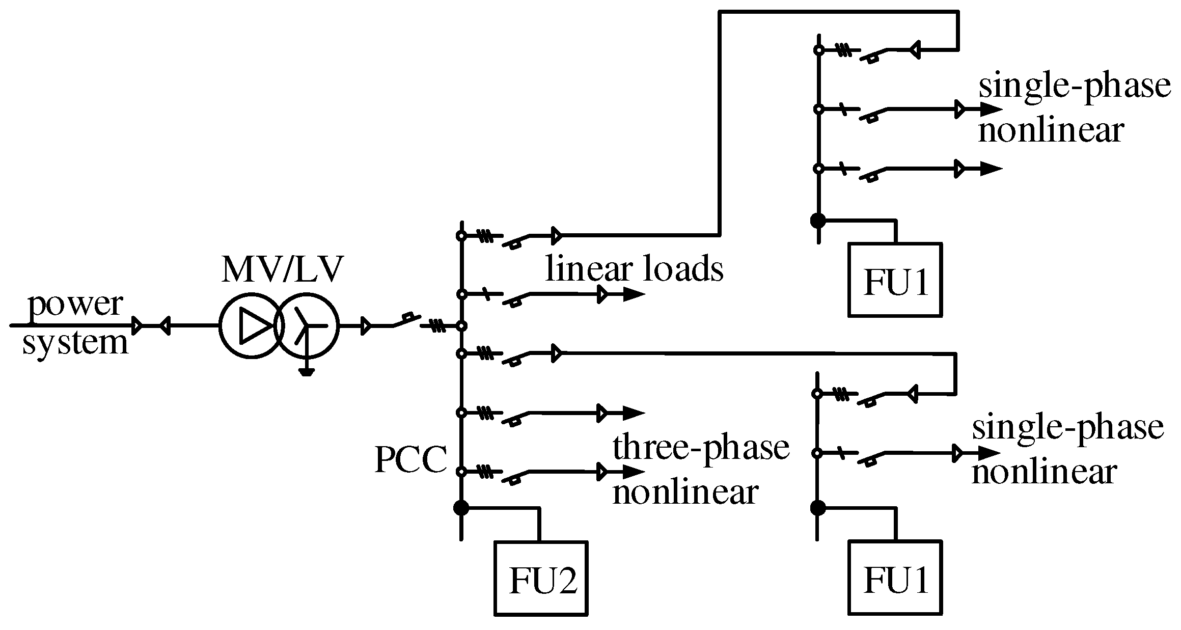
The configuration of the proposed distributed PQ conditioning system is shown in
Figure 1. The system contains filter units of two types. The Filter Unit of the first type (FU1 in
Figure 1) is used for neutral-line currents attenuation. Since most of single-phase non-linear loads producing zero-sequence currents are connected to the network nodes inside the building, FU1 are distributed along the three-phase network and are installed in such nodes.
The Filter Unit of the second type (FU2 in
Figure 1) is a three-phase hybrid filter consisting of a passive power filter and a three-phase inverter connected in parallel to the passive filter or in series with the external network. The FU2 is used to compensate negative-sequence voltage components and current harmonics caused by three-phase non-linear loads. It is recommended to connect such units to the secondary winding of the step-down transformer at the building entrance facility or in nodes that are connected to a load sensitive to PQ problems.
The proposed configuration of distributed PQ conditioning system is open, easy to be modified by installing new units. Failure of one unit does not affect the efficiency of filter units in other nodes of the network. The distributed nature of compensating system reduces the cost of the system and increases its reliability.
3. Hybrid Filter for Neutral Current Attenuation
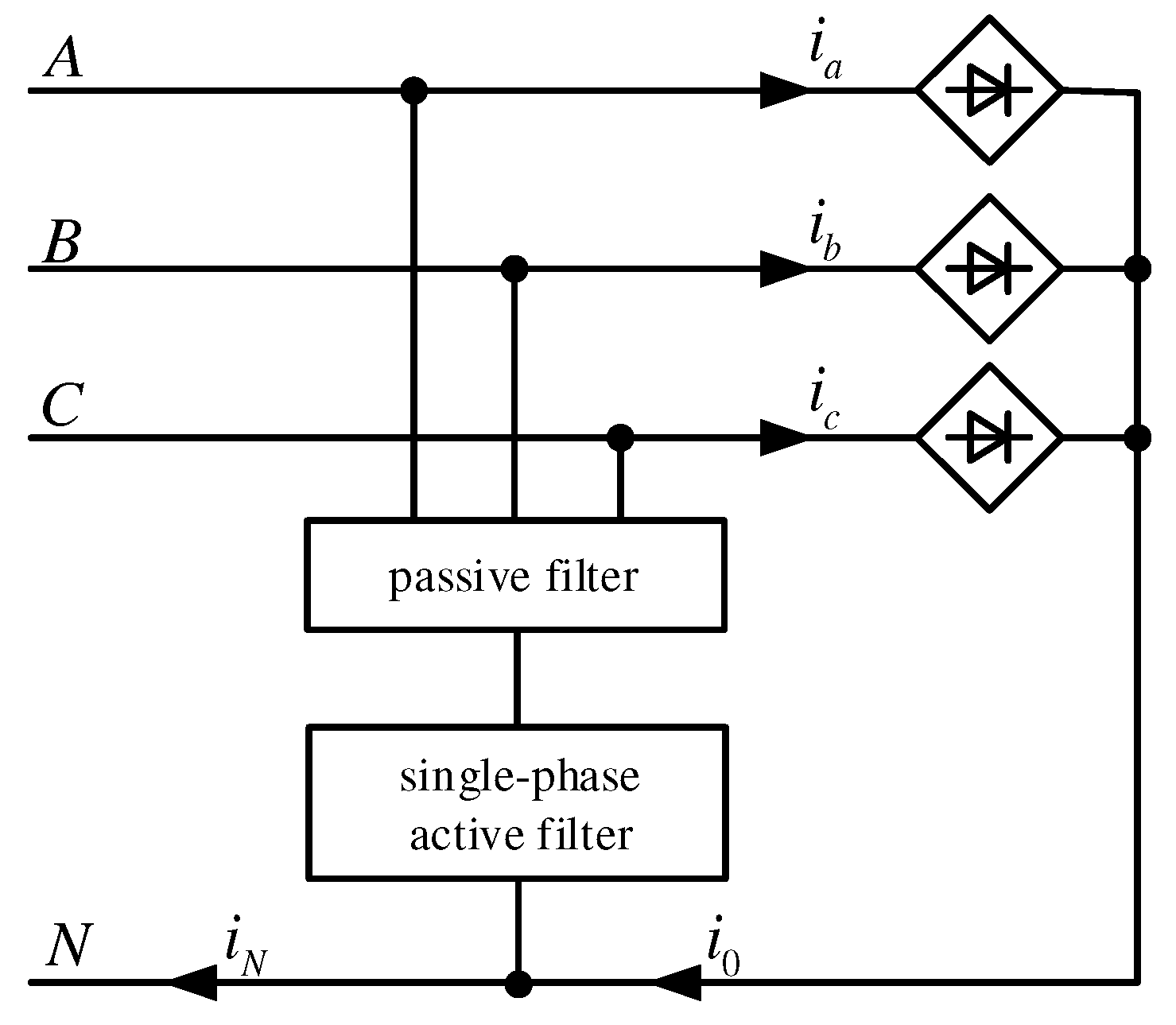
Consider the configuration of devices for neutral current attenuation. The filter unit of the first type (FU1) is a hybrid power filter constituted by series connection of a passive filter and a single-phase voltage inverter (
Figure 2). It is used for neutral-line current attenuation.
The single-phase power converter in
Figure 2 functions as an active filter. Inverter voltage is proportional to fundamental and harmonic components of the neutral conductor current:
where
,
are the control parameters of the active filter;
is the neutral-line fundamental current component;
is the neutral-line harmonic current component.
The control parameters of the active filter
and
have frequency characteristics of notch and band-pass filters tuned to fundamental frequency:
where
is the fundamental frequency.
The zero-sequence equivalent network of three-phase four-wire power system with proposed hybrid filter is shown in
Figure 3.
Here the voltage source models zero-sequence component of supply voltage and the current source models zero-sequence component of the load current. The active filter is modeled by the current controlled voltage source.
According to
Figure 3 the neutral conductor current can be derived as
As follows from the Formula (1) the operation of the active filter is equivalent to inserting the resistance
into the neutral line. This reduces the current in the neutral conductor and the voltage between the neutral points. It should be noted that the hybrid filter in
Figure 2 also attenuates the zero-sequence current and voltage components created by the external network.
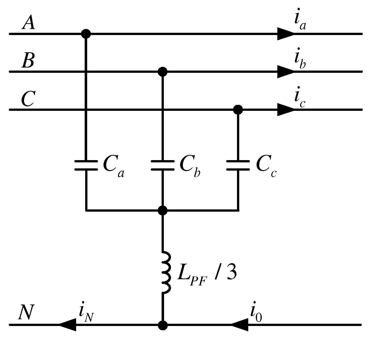
In the simplest case, a resonant circuit tuned to the frequency of the dominant third harmonic can be used as a passive filter (
Figure 4).
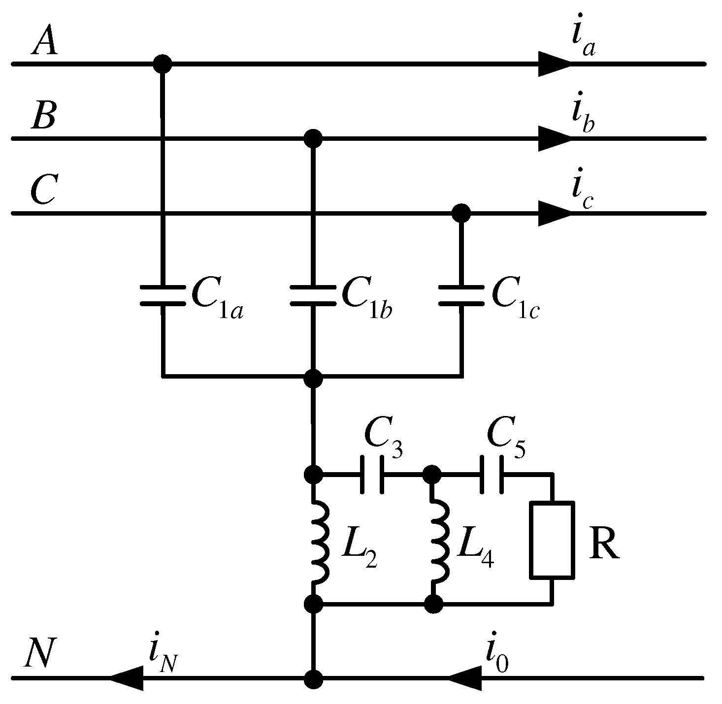
However, in case of asymmetric nonlinear load, nontriplen harmonics also form the zero sequence system. Therefore, a high-pass passive filter with low impedance in the frequency range
Hz is a more efficient solution. The high-pass filter is shown in
Figure 5. The passive filter in
Figure 5 contains the ladder LC-two-port and the damping resistor. The filter order can be varied by changing the order of the LC-two-port.
Figure 6 shows the frequency characteristics of the zero sequence current transmission coefficients when using single-tuned and high-pass passive filters. The parameter of the active filter is
.
The proposed broadband hybrid filter attenuates the wide spectrum of neutral line current harmonics. An additional advantage of a high-pass passive filter is its less sensitivity to LC network parameter variations.
4. Three-Phase Hybrid Power Filters for Voltage Distortion Compensation
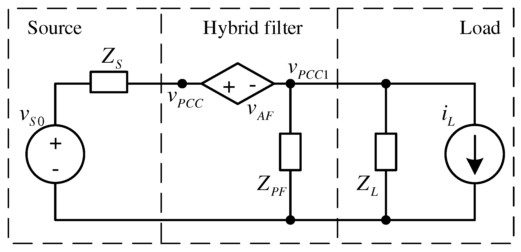
Filter unit 2 in the proposed conditioning system is a three-phase hybrid power filter designed to compensate nonzero-sequence voltage components and harmonics caused by three-phase non-linear loads. In UPQC, the series active filter provides the desired voltage control at the point of common coupling (PCC).
The combined system of the shunt passive filter and the series active filter was first proposed in [
17]. The block diagram of the filter is shown in
Figure 7.
The voltage source models the supply voltage. The current source models load current. The voltage of an active filter is proportional to current harmonics: . The value of the active filter parameter is high for harmonic components and equals zero for fundamental component of the load current. To effectively attenuate the non-linear load current harmonics, the value of the active filter parameter must be high, which is a major disadvantage of this type of the filter.
One more control technique of a series active filter is proposed in [
18]. In this case, the voltage of an active filter in
Figure 7 is proportional to the voltage harmonics at the point of common coupling (PCC):
. The method discussed in [
18] can be used to compensate source voltage unbalance and load current harmonics.
A strategy for controlling a series active filter known as the voltage synchronization method aimed at making compensating device and load equivalent to the symmetric linear resistive circuit is proposed in [
19]:
where
,
—are the phase voltage and current vectors. This strategy ensures perfect harmonic compensation.
A disadvantage of series active filters is that they are connected to the network through a coupling transformer. Using of coupling transformer increases installation cost. The series active filter is suitable for a new installations but not suitable as a retrofitting device [
2].
Figure 8 shows a block diagram of a hybrid shunt filter. As seen in
Figure 8 the active filter is modeled by a controlled current source. The shunt active and hybrid filters for three-phase four-wire networks are discussed in [
20,
21,
22].
Various strategies for perfect harmonic and unit power factor compensation are used to control active filters. However, in this case, the power of the active filter is comparable to the power of the distortion load. In most cases, it is not necessary to ensure perfect compensation of voltage distortions. It is enough to reduce them to values equal to those determined by standards. Moreover, the authors of [
20,
21] did not take into account the interaction of passive and active filters and their effect on the characteristics of the hybrid device.
In this section the topologies of three-phase hybrid filters that provide selective compensation of voltage distortions caused by asymmetry and non-linear loads, are considered.
4.1. Case 1
Combined structure with a series active filter (
Figure 7). The active filter voltage is proportional to voltage components at point PCC1:
where
—is fundamental voltage component, which forms a negative sequence symmetric system;
—voltage harmonics;
and
—active filter parameters.
As seen in
Figure 7 the
k-th harmonic voltage harmonic voltage at the point of common coupling can be derived as
where
and
are the
k-th harmonic network voltage and load current components, respectively.
According to the Formula (2) the filter compensates asymmetry and harmonic voltage distortion at the PCC. The level of compensation can be varied by changing the parameters and . Perfect harmonics compensation is achieved when .
4.2. Case 2
Shunt hybrid filter with voltage feedback (
Figure 8). It combines a passive filter and a three-phase active filter controlled by voltage components at the point of common coupling.
The active filter current is proportional to the fundamental and harmonic voltage components at the point of common coupling and can be expressed as
where
, is a fundamental voltage component, which forms a negative sequence symmetric, system
are voltage harmonics.
The
k-th harmonic voltage at the point of common coupling can be derived as follows:
A shunt hybrid filter with voltage feedback attenuates components of distorted voltage caused by unbalanced and non-linear loads. The level of attenuation of fundamental and harmonic components depends on the active filter parameter and the passive filter admittance at the frequency of the k-th harmonic.
4.3. Case 3
A shunt hybrid filter with voltage feedback and load current feedforward. The active filter current is proportional to components of the current
and voltage
in
Figure 8 and can be expressed as
where
—is the harmonic component of the load current;
—is the fundamental negative-sequence component of the load current;
—are voltage harmonics;
is a negative sequence fundamental voltage component.
The voltage of the
k-th harmonic in the point of common connection of the nonlinear load and hybrid filter is derived as follows
where
and
are the
k-th harmonic supply network voltage and load current components, respectively,
is the supply network admittance. The values of parameters
and
do not exceed 1.
This method exhibits the best compensating performance. The perfect harmonic compensation is achieved when . In accordance with (4), the hybrid filter attenuates harmonics and negative sequence voltage components generated by the load and the external network.
The described above options of hybrid power filters selectively compensate fundamental and harmonic voltage components caused by asymmetry and nonlinear nature of loads. By changing the active filter parameters it is possible to vary the level of fundamental and harmonic components attenuation.
5. Optimization of Hybrid Filter Compensation Characteristics
The hybrid filter structures described in [
17,
18,
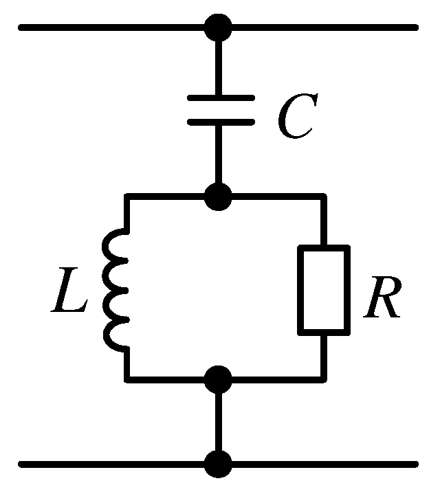
19] use simple passive filters consisting of two single-tuned branches for 5th and 7th harmonics mitigation. However, non-sinusoidal currents produced by multiple distributed non-linear loads have wide spectrum. Therefore, the conventional narrow-band filters do not always produce the desired effect. In addition, the passive filter must attenuate high-frequency harmonics generated by the three-phase inverter. To reduce the power of the active filter, it is recommended to use high-pass filters with a wide-band attenuation range. The simplest second-order high-pass filter is shown in
Figure 9.
The disadvantages of the second-order high-pass filter are poor selectivity and big fundamental power losses. In order to reduce fundamental power losses and improve selectivity, it is necessary to increase the order of the filter.
Figure 10 represents the high-pass filter in the form of a single-loaded ladder LC-two-port. It is known that the real part of the driving point admittance
of the LC-two-port is determined by the square of the transfer function modulus [
23]
where
is a transfer function of the two-port,
is a load conductance.
As follows from the Formula (5), in order to obtain the desired frequency response in the attenuation band, it is necessary to use a two-port implementing the transfer function of the high-pass filter.
The analytical calculations of the 3rd to 5th order passive filter are generally very cumbersome. We use optimization methods to determine hybrid filter parameters. The optimization problem is formulated as follows: Find the minimum value of the objective function
provided the constraints are satisfied:
In Formulas (6–8), the following designations are used: is filter input admittance at the k-th harmonic frequency ; is grid admittance at the frequency ; —the rms value of the load current harmonic; is the maximum value of the active filter parameter. The parameter in inequality (7) determines permissible ratio value between active and reactive powers of ladder passive filter at fundamental frequency.
The values of the passive filter elements and the active filter parameter are the variable parameters used in the optimization process.
The objective function (6) was minimized by using Optimization Toolbox of MatLab software. was optimized applying direct search technique of Nelder and Mead. Element values of high-pass Butterworth filter were used as the starting point.
The proposed design procedure takes into account nonlinear load current spectrum, frequency characteristics of the external system as well the effect of the passive and active filters on the characteristics of the hybrid device.
Element values of the fifth-order passive filter (
Figure 10), obtained with the proposed design procedure are shown in
Table 1.
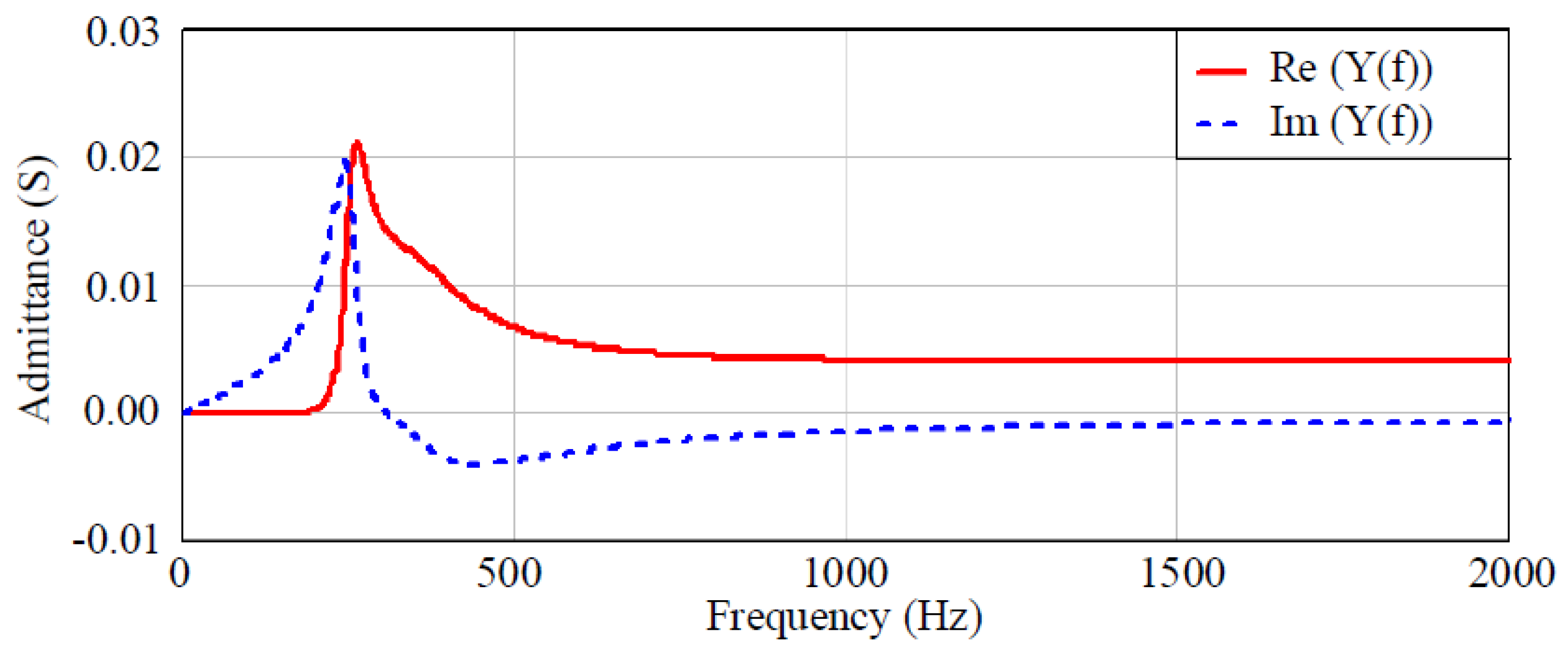
Frequency characteristics of passive filter admittance are shown in
Figure 11. As seen in
Figure 11 in the attenuation band passive filter is equivalent to parallel RL circuit.
The hybrid power filter combines the characteristics of passive and active parts. The passive filter determines frequency characteristic in the attenuation band. The level of attenuation is controlled by the active filter.
6. Digital System of Control Signals Computation for Active Filters
The proposed PQ conditioning system can be used to attenuate neutral conductor currents, compensate harmonic distortions, voltage asymmetry, etc. Its characteristics depend on the methods used to generate control signals for active filters.
Currently, active filter control strategies, based on application of instantaneous reactive power theory (p-q theory) [
24,
25,
26,
27] first proposed by H. Akagi and his colleagues, or instantaneous values of symmetrical components in three-phase network considered in [
28,
29] are used. In this case, it is advisable to use a strategy for computing control signals based on the use of instantaneous symmetric components, since the conditioning system selectively compensates the zero and negative sequence components of voltages and currents. In addition, a strategy based on the use of symmetric components requires less computation [
28,
29].
The control signal generation procedure includes the following operations [
24]:
Signal measurement and harmonic detection.
Generation of reference compensation signal in accordance with the selected compensation strategy.
Generation of active power filter control signal using hysteresis method or pulse width modulation (PWM).
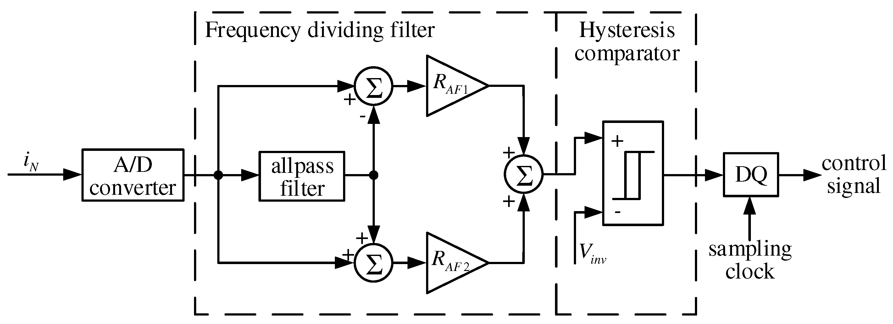
The digital system of computing control signals for active filters consists of two parts. The first part (shown in
Figure 12) provides control of a single-phase inverter for Filter Unit 1. It includes a frequency dividing filter (FDF) and the gating signals generator. FDF realizes transfer functions of band pass and notch filters simultaneously. The notch filter extracts fundamental component from the input signal. Its output signal consists of harmonic components. The band-pass filter extracts harmonic components from the input signal and its output signal includes only a fundamental component. Therefore the notch frequency
and bandpass filter center frequency
must be equal to fundamental frequency of the input signal.
The three-phase hybrid filter is used to obtain phase voltages of fundamental frequency, which form a direct sequence voltage at the point of common coupling (PCC). It is necessary to weaken the other components of phase voltages caused by nonsymmetrycal and non-linear loads at the PCC. For this, the inverter currents must be proportional to phase voltage components to be compensated.
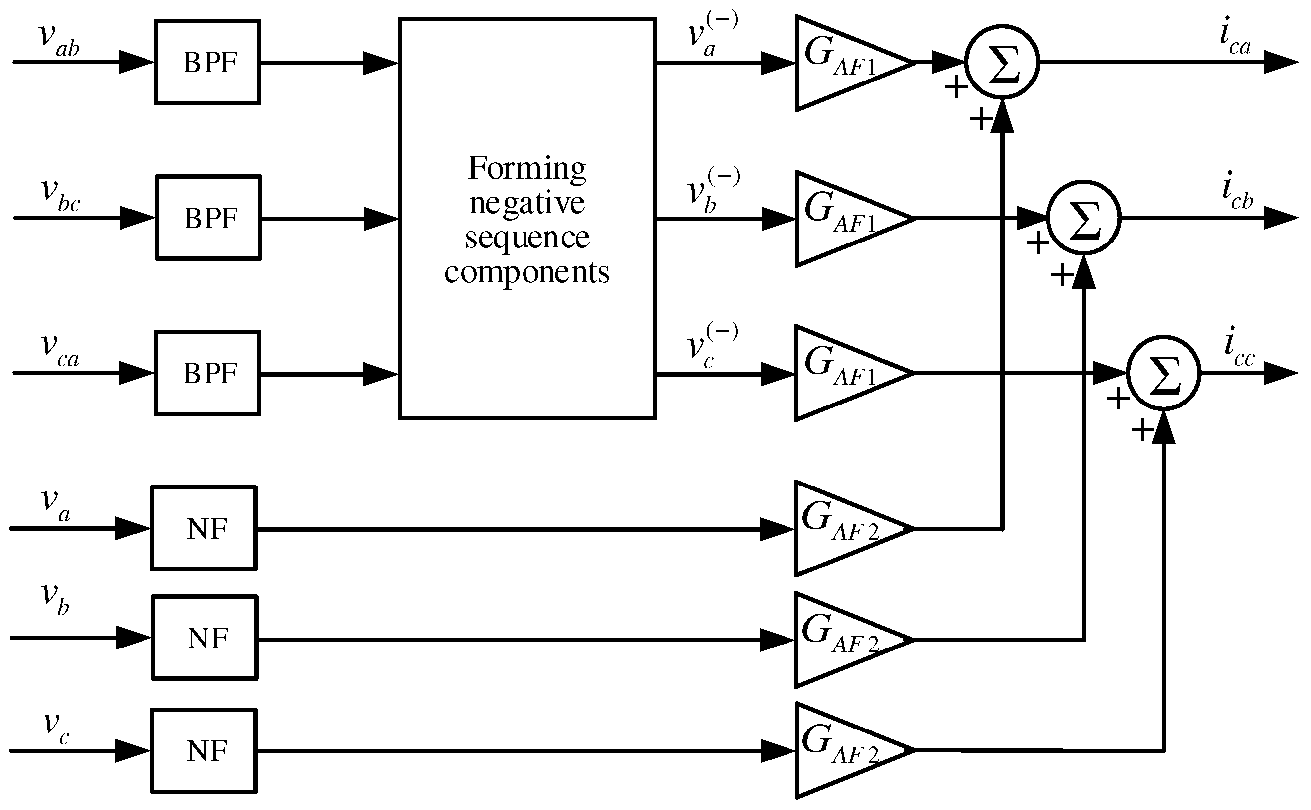
The block diagram of reference signal computation system for three-phase active filter with voltage feedback is shown in
Figure 13. The signals proportional to network voltages at the PCC are applied to the inputs of band-pass and notch filters (BPF and NF in
Figure 13). When the components with fundamental and harmonic frequency are separated, fundamental frequency signals are applied to the input of symmetric components computation unit. The fundamental frequency negative sequence voltages are the output signals of the unit.
The control signal computation systems for other variants of active filters considered in
Section 4 are characterized by a similar structure.
The frequency dividing digital filter is a key component of the control signal generation system. In most cases, adaptive finite impulse response (FIR) filters in the form of digital delay line are used to extract of fundamental and harmonic components. FIR filter employs the least mean square algorithm to adjust the coefficients [
29]. The drawback of FIR filters are poor selectivity and low adaptation speed.
In this paper frequency dividing filter is implemented based on a second-order all-pass filter with infinite impulse response (IIR filter) [
30]. According to
Figure 12 transfer functions of the notch and banpass filters are
where
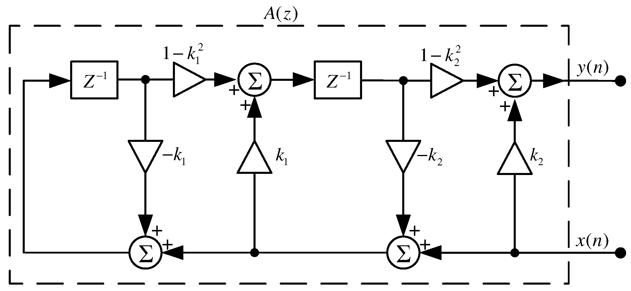
denotes the transfer function of the all-pass filter. The structure of the lattice form all-pass IIR filter is shown in
Figure 14.
On the diagram in
Figure 14,
and
are the input and output samples respectively. The transfer function of the all-pass filter can be represented as
The numerator and denominator polynomials of the transfer function
are mirror image polynomials. Thus, the lattice IIR filter in
Figure 14 implements all-pass transfer function with
and
where
is the notch frequency and B is suppression bandwidth of the notch filter.
The transfer function of the notch filter in
Figure 12 has the form
Since the numerator polynomial coefficients are symmetric,
has its zeros on the unit circle. The suppression frequency can be controlled by the parameter
and the suppression bandwidth by acting on the parameter
.
Transfer function of the band-pass filter has the form
The frequency dividing filter must provide adaptive monitoring of the fundamental power system frequency. The adaptive algorithms to adjust the digital notch filter parameters were discussed in [
30,
31,
32,
33,
34]. A method based on the use of adaptive lattice filters with finite impulse response can be used to adjust the frequency dividing filter in
Figure 12 [
33,
34].
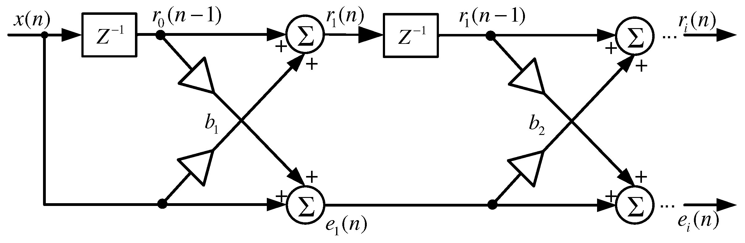
The finite impulse response lattice digital filter is shown in
Figure 15.
In
Figure 15 and
are forward and backward prediction errors at the output of the filter, respectively. The coefficients
are called reflection coefficients.
The second order FIR filter in
Figure 15 implements two transfer functions simultaneously
Transfer functions and have a minimum at frequency .
As it follows from (9) and (11) the filters notch frequencies in
Figure 14 and
Figure 15 coincide provided that the following condition is satisfied
Thus, the adjustment of the transfer function of the infinite impulse response filter is equivalent to the adaptation of the lattice finite impulse response filter. This simplifies the procedure for adjusting the infinite impulse response filter by using adaptive algorithms of a non-recursive lattice structure.
To estimate the coefficients of the lattice finite impulse response filter, we use a gradient algorithm determined by the formula [
33]
where
—is the initial step of adaptation. The parameter
is determined by the formula
In the last expression is a forgetting factor: . This parameter helps to select the adaptation step separately for each section.
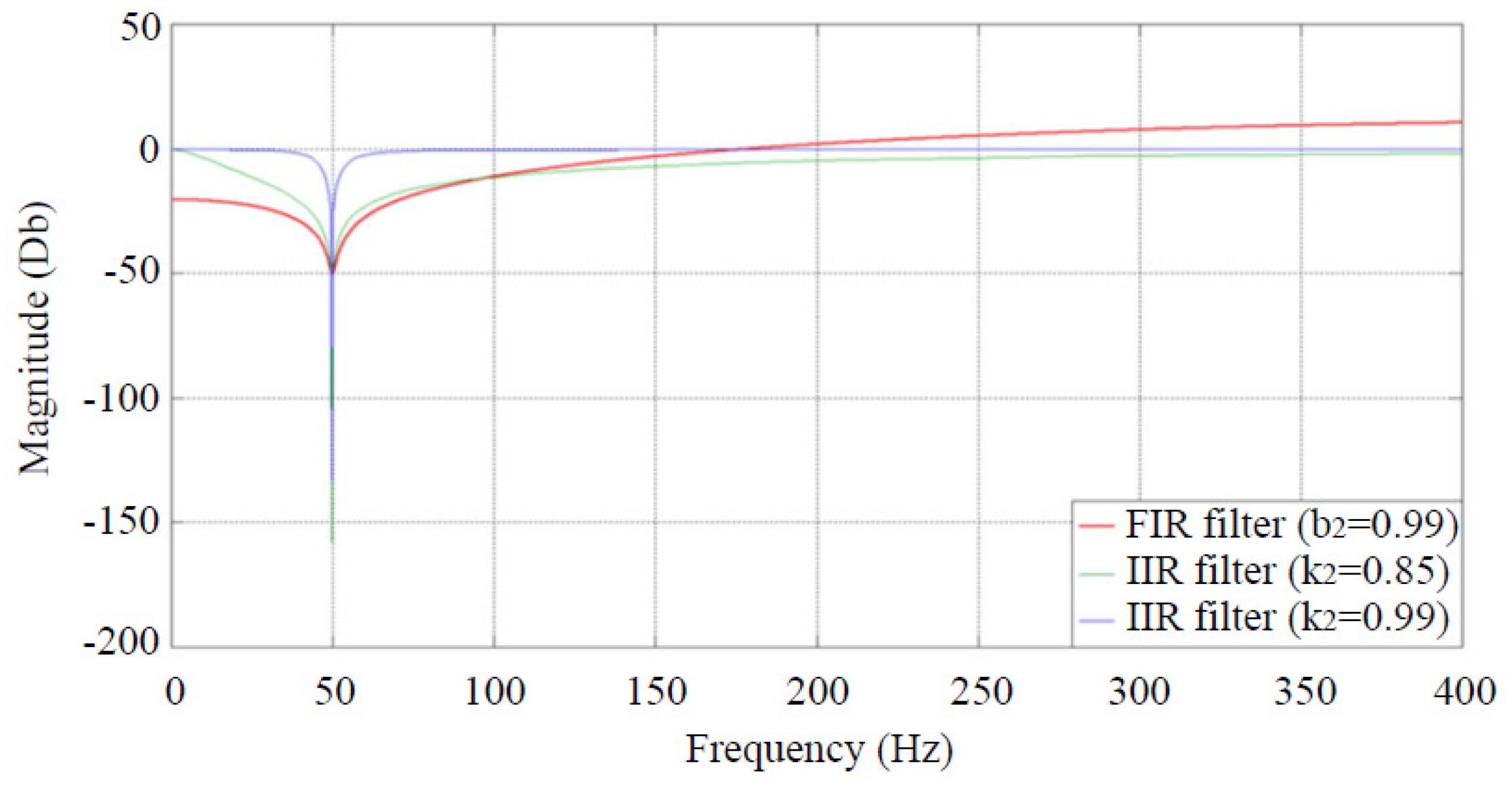
Amplitude characteristic of the notch filter tuned to fundamental frequency 50 Hz is shown in
Figure 16.
It is seen from
Figure 16, IIR filter showed substantial better selectivity than FIR filter of the same order. It can also be found from
Figure 16 that suppression effect of the IIR notch filter depends on the value of the parameter
.
7. Hybrid Power Quality Conditioning System Simulation
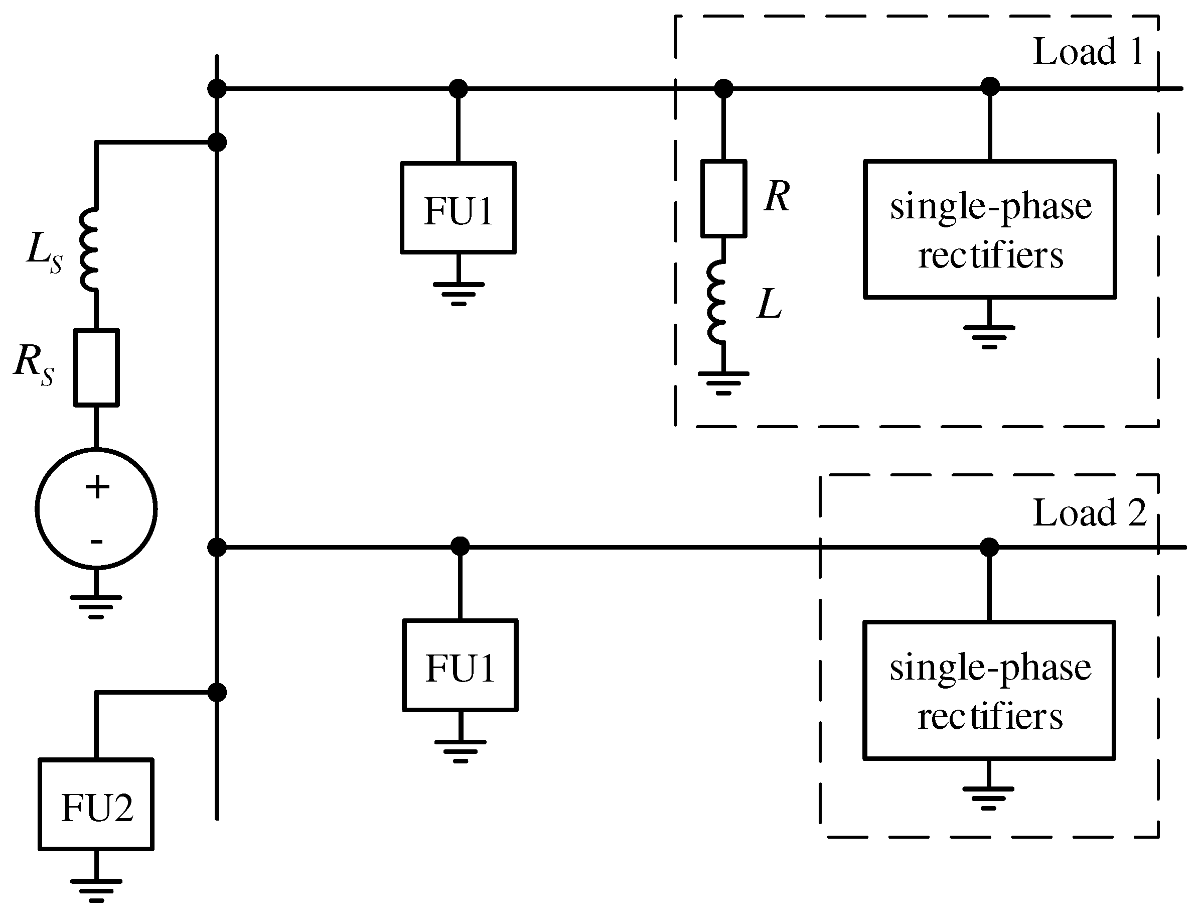
The distribution system supplying two three-phase nonlinear loads was simulated using the MatLab/Simulink software.
Figure 17 shows a simplified single-line diagram of the distribution system.
The supply system parameters are: Resistance Ohm, and inductance mH.
The Load 1 is composed of three single-phase rectifiers and linear unbalanced load. Rectifier parameters in Load 1 are: Load resistance Ohm, and filter capacity F. The parameters of unbalance linear load are: Load resistance Ohm, and inductance mH in phase A; load resistance Ohm, and inductance mH in phases B and C.
The Load 2 consists of three single-phase rectifiers. Rectifier parameters in Load 2 are: Load resistance Ohm, and filter capacity F.
Filter units 1 are installed at the points of common coupling with nonlinear loads. FU1 are implemented by a passive high-pass filter and a single-phase inverter. A shunt hybrid filter with voltage feedback is used as FU2.
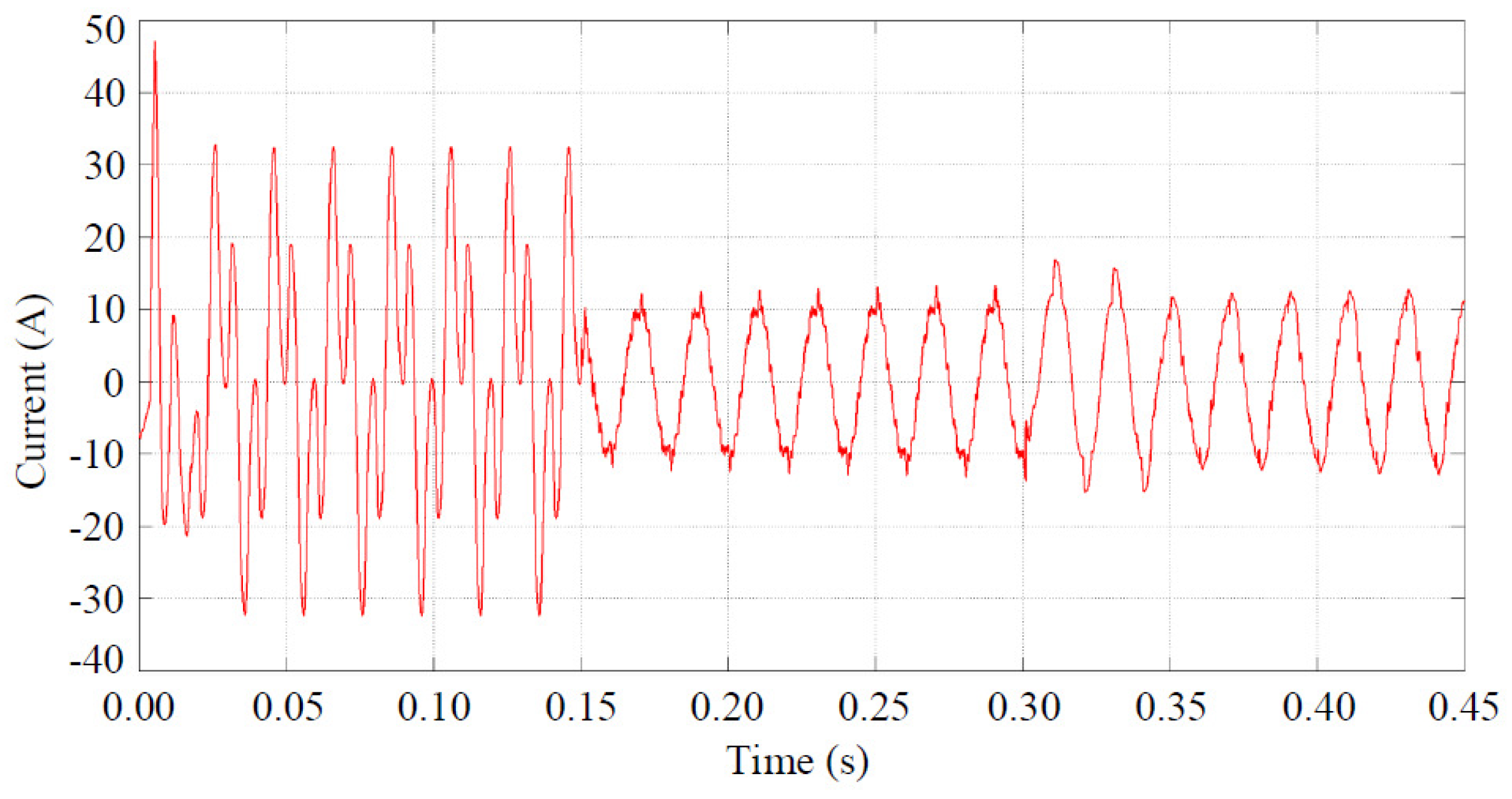
The FU1 run at the moment
s. FU2 runs at the moment
s. The Load 1 neutral current
diagram in the interval 0.05–0.45 s. is shown in
Figure 18.
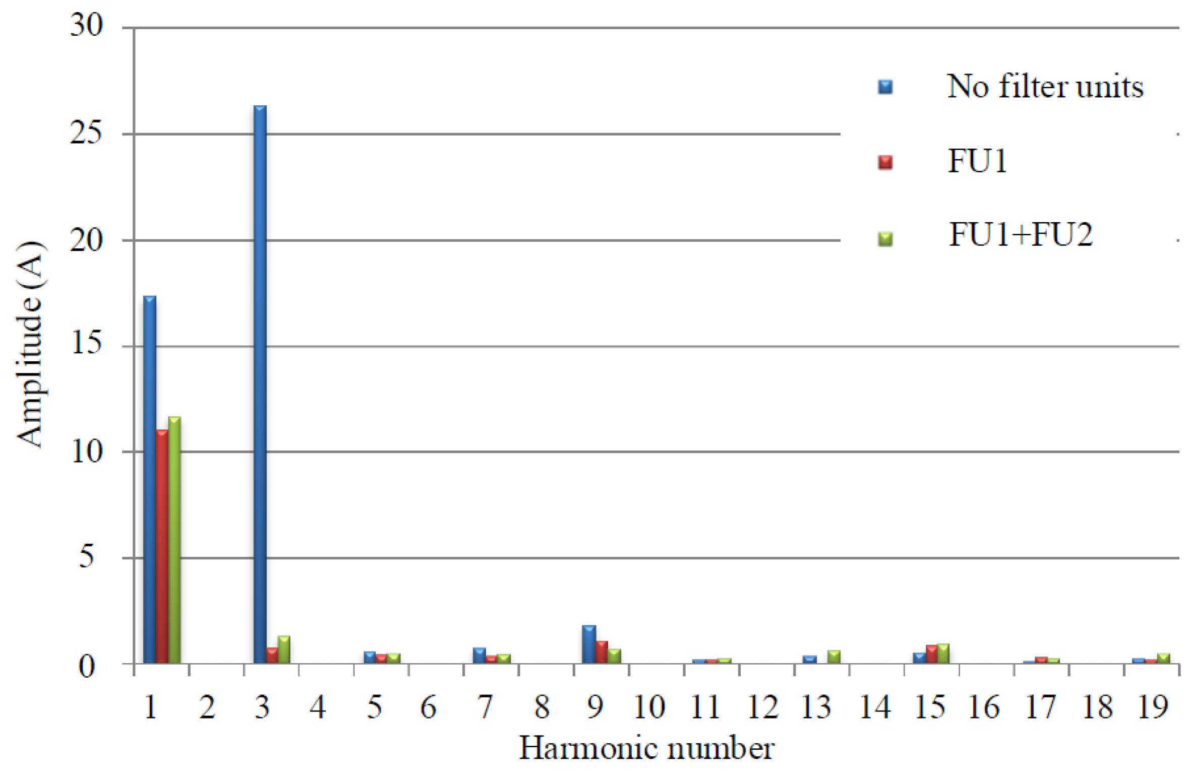
Figure 19 shows the current
spectrum.
Figure 20 shows the source neutral current
diagram. The current
spectrum is shown in
Figure 21.
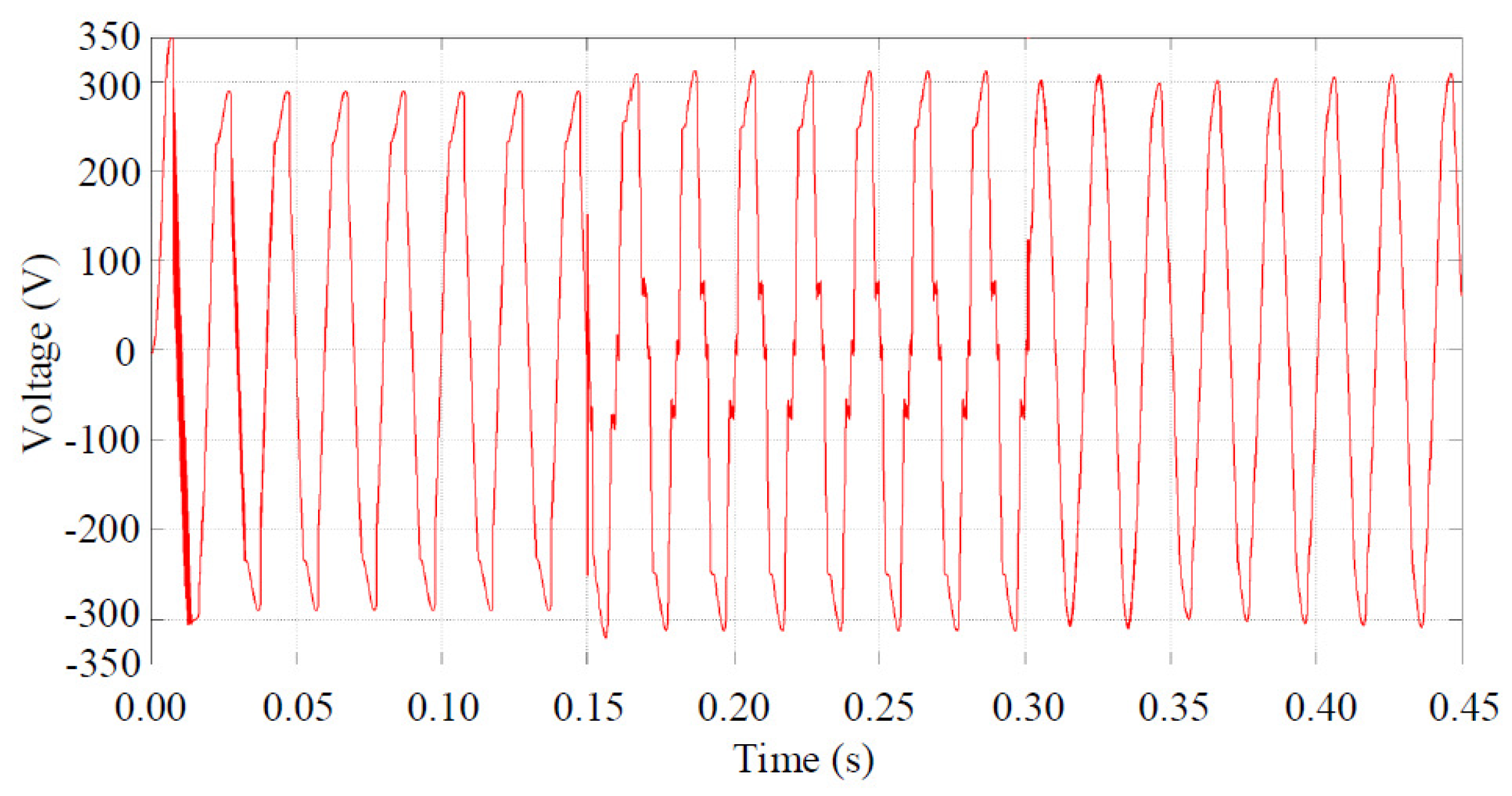
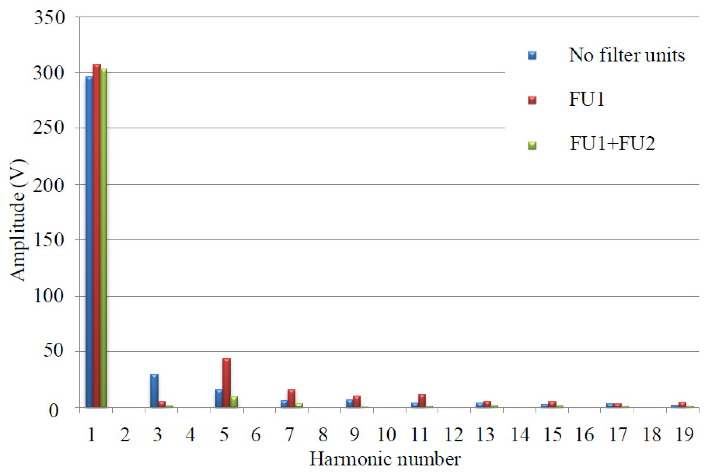
The source phase to neutral voltage
waveform is shown in
Figure 22. As seen, the phase voltages are nearly sinusoidal after 0.3 s. Voltage
spectrum is shown in
Figure 23.
The simulation results are summed in
Table 2.
is the total harmonic distortion factor:
is the voltage unbalance factor:
The simulation results indicate that the proposed PQ conditioning system can attenuate neutral conductor currents and compensate voltage distortions caused by unbalanced nonlinear loads. The voltage asymmetry has been reduced by more than three times. Total harmonic distortion of phase currents and voltages has also been significantly attenuated. The compensation level of fundamental and harmonic components may be varied by the active filters parameters.
8. Conclusions
The wide use of non-linear single-phase loads is the main reason of power quality problems in three-phase four-wire low-voltage networks. Unbalance and non-sinusoidal nature of currents and voltages have a serious negative impact on the power quality and reduce the efficiency of power supply systems.
The contributions of this paper can be summarized as follows.
1. The distributed power quality conditioning system for three-phase four-wire low voltage networks, providing attenuation of neutral conductor currents and compensation of voltage distortions caused by unbalanced nonlinear loads, is considered. The system consists of several hybrid filter units, providing compensation of excessive neutral currents and voltage distortions in selected areas of distribution system. The proposed PQ conditioning system is open, easy to be modified by installing new filter units.
2. The proposed filter units provide selective compensation of fundamental and harmonic components in distorted voltages and currents.
3. A novel hybrid filter design procedure based on optimization of frequency characteristics in the space of passive and active filter parameters is proposed. It takes into account nonlinear load current spectrum, frequency characteristics of the supply system as well the influence of passive and active filters on the characteristics of the hybrid device.
4. A digital system of reference control signals computation for active filters based on the modern methods of spectral analysis is considered. It has better selectivity and adaptation speed as compared with traditional systems using FIR filters. The use of proposed system enables selective compensation of fundamental and harmonic components.
A mathematical model of the proposed power quality conditioning system is developed in the MatLab software. The model is used to study the compensation characteristics of the system. The simulated results show that the proposed conditioning system can reduce neutral conductor currents as well as voltage asymmetry and harmonic distortions produced by unbalanced nonlinear loads.
The direction of future work is optimum allocation of filter units and unified control strategy for active filters.

 ,
, 


