The Impact of the Ventilation System on the Methane Release Hazard and Spontaneous Combustion of Coal in the Area of Exploitation—A Case Study

 ,
,  ,
,  ,
, 
Abstract
1. Introduction
1.1. Preliminaries, Objectives and Outline of the Study
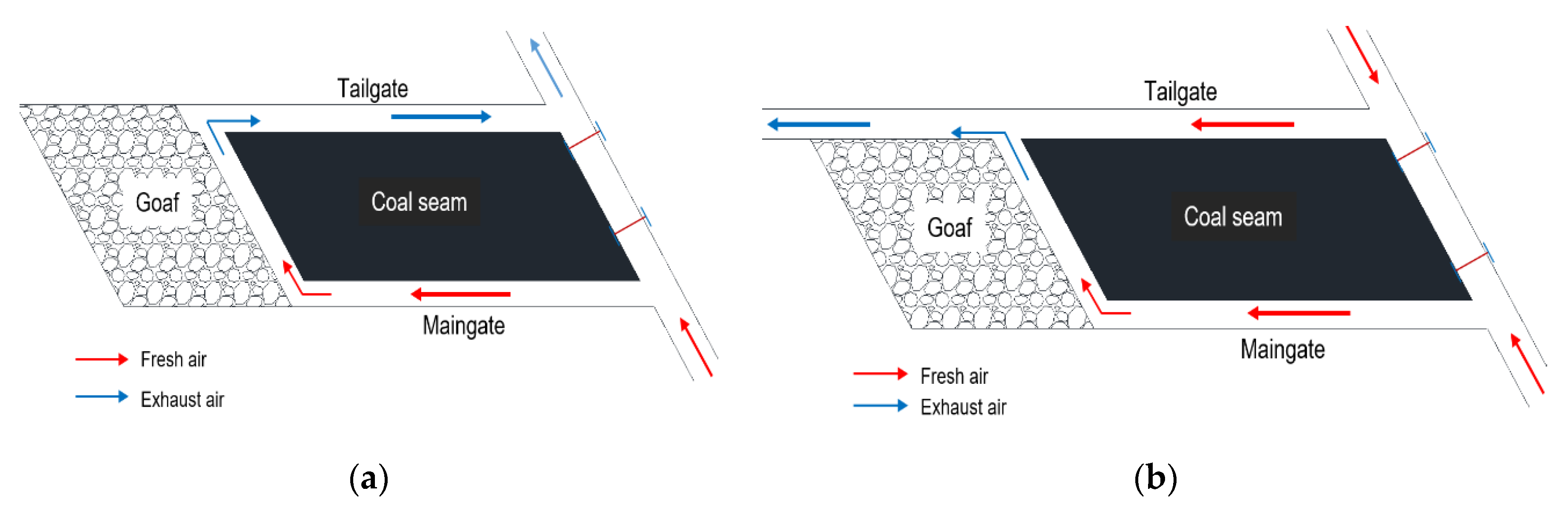
1.2. Brief Literature Review of Ventilation of Longwalls and Methane and Coal Spontaneous Combustion Hazards
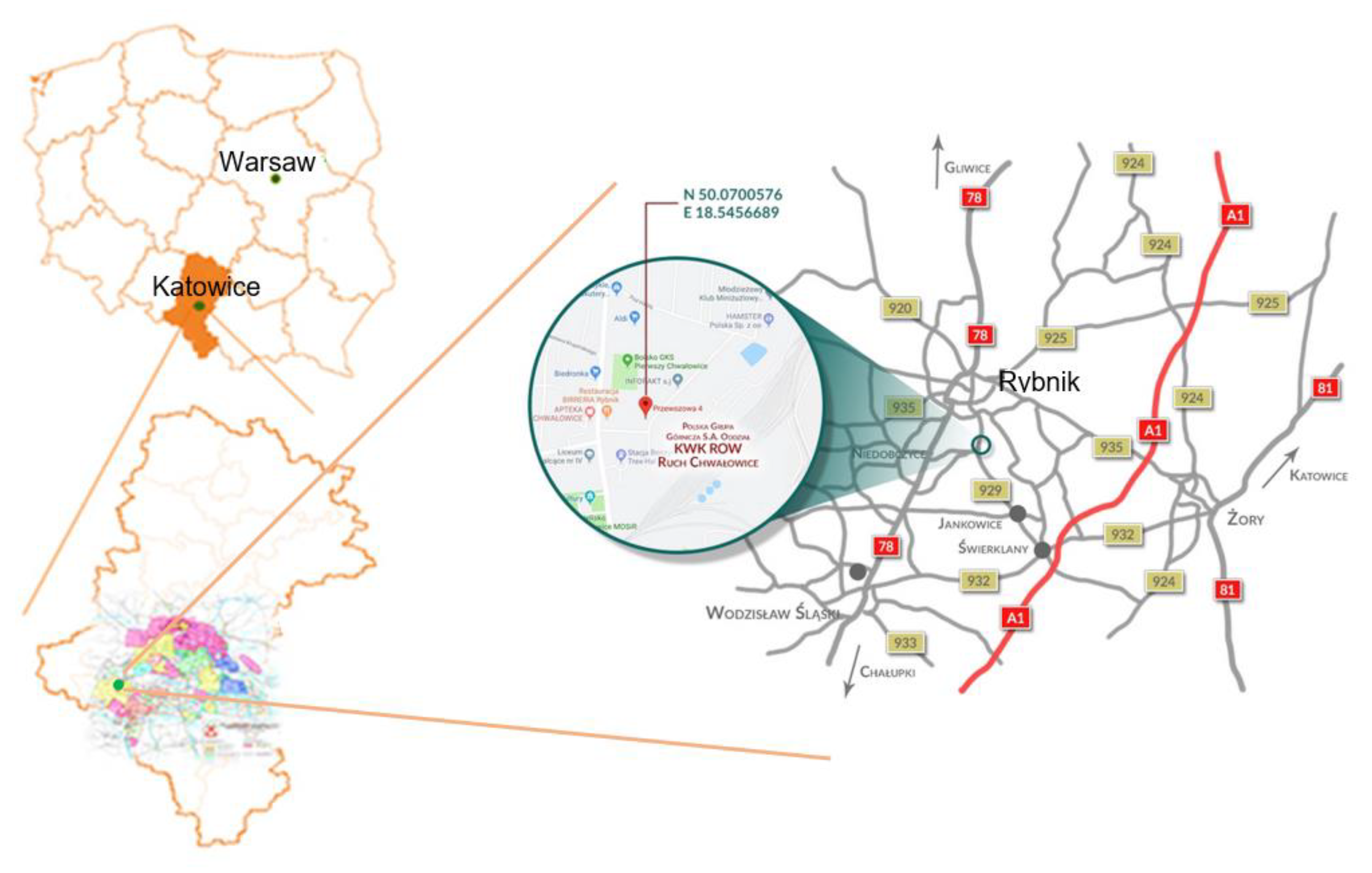
2. Materials and Methods
3. Results
3.1. Analysis of the Methane Release Hazard
3.2. Analysis of the Coal Spontaneous Combustion Hazard
4. General Discussion
5. Conclusions
- -
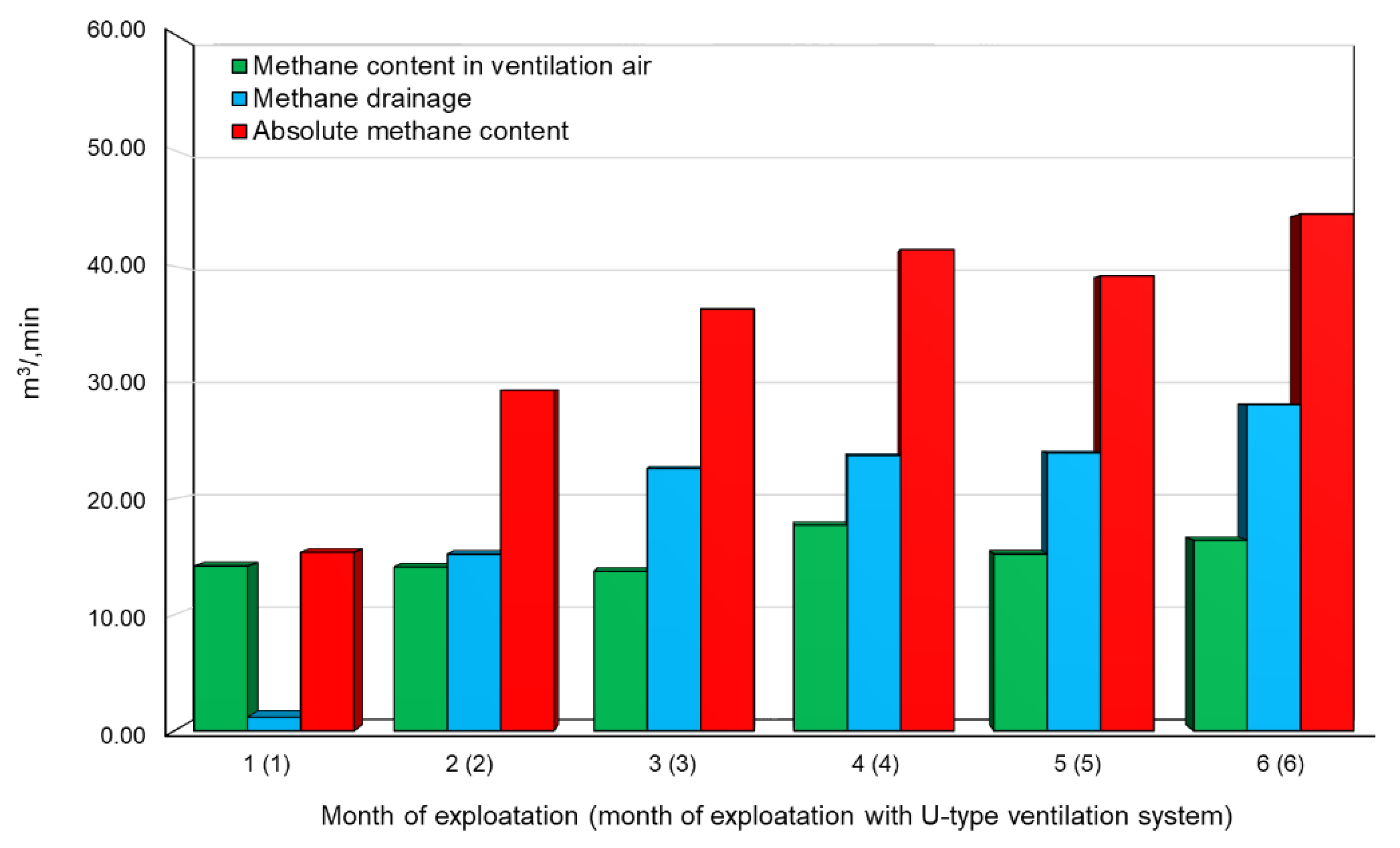
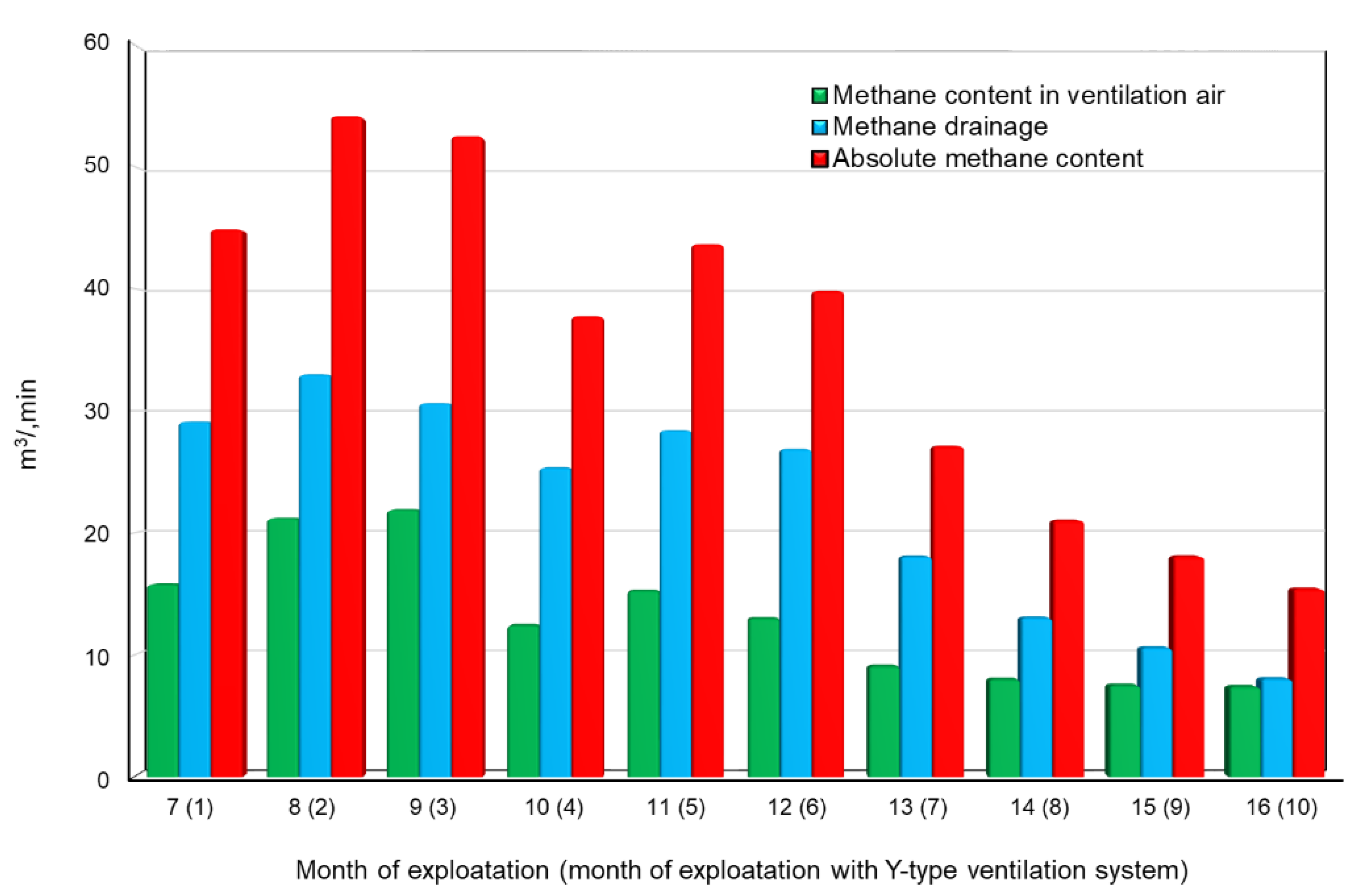
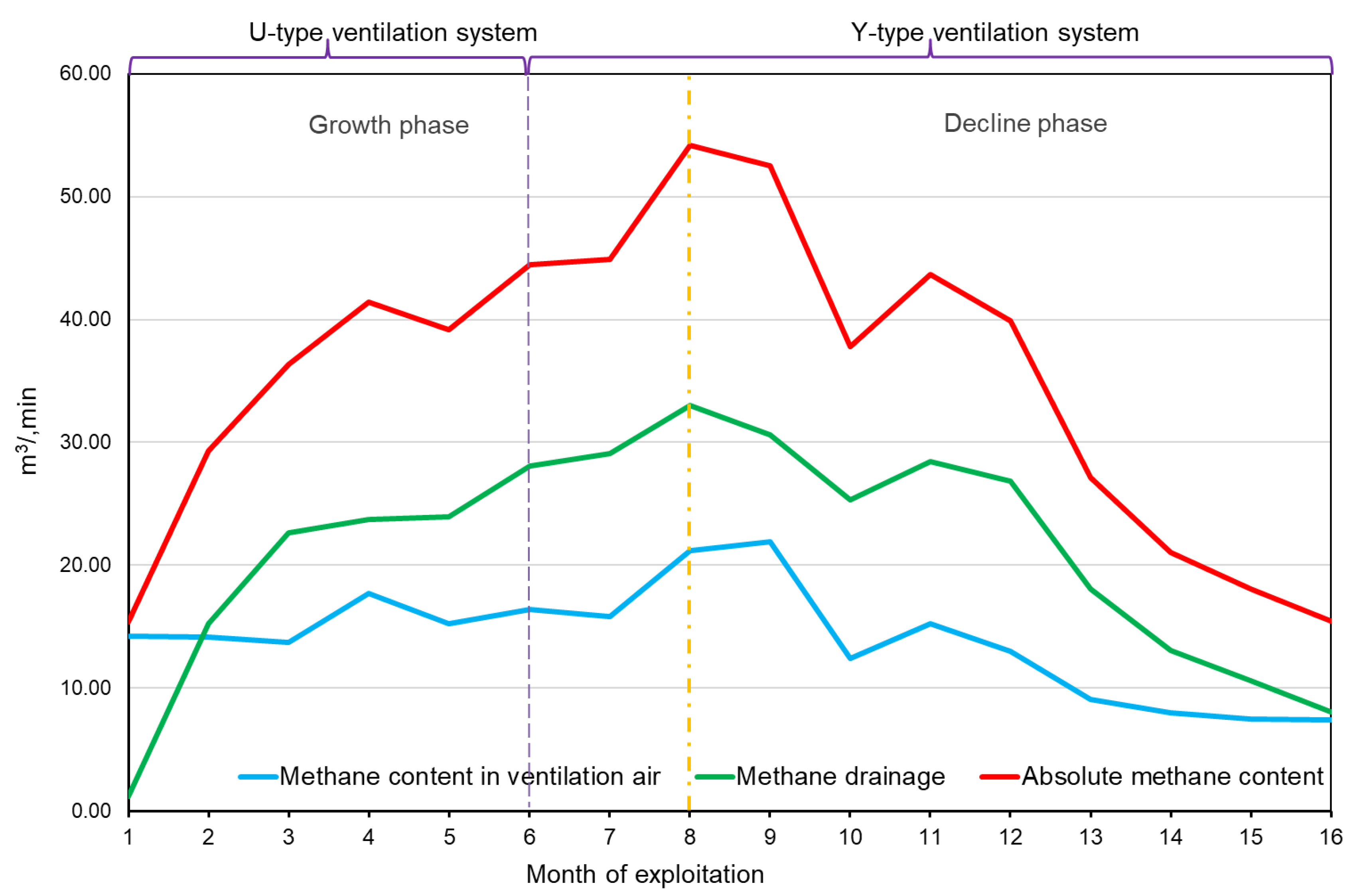
- The average absolute methane content reached 34.37 m3/min in the case of the U-type ventilation system, and 35.46 m3/min for the Y-type ventilation system. The average ventilation methane content related to the volume content of methane in the ventilation air for the U-type system was 15.24 m3/min, and 13.15 m3/min for the Y-type system. The methane drainage system drained 19.13 m3/min of methane for the U-type ventilation system, and 22.31 m3/min in the case of the Y-type ventilation system;
- -
- The ventilation methane content of the longwall when using the U-type system was almost 14% higher compared to the Y-type system. At the same time, the absolute methane content of the longwall when using the U-type ventilation system was lower than in the case of the Y-type system;
- -
- The efficiency of the methane drainage system increased in the case of the Y-type ventilation system—on average, 14% more methane was drained compared to the U-type system;
- -
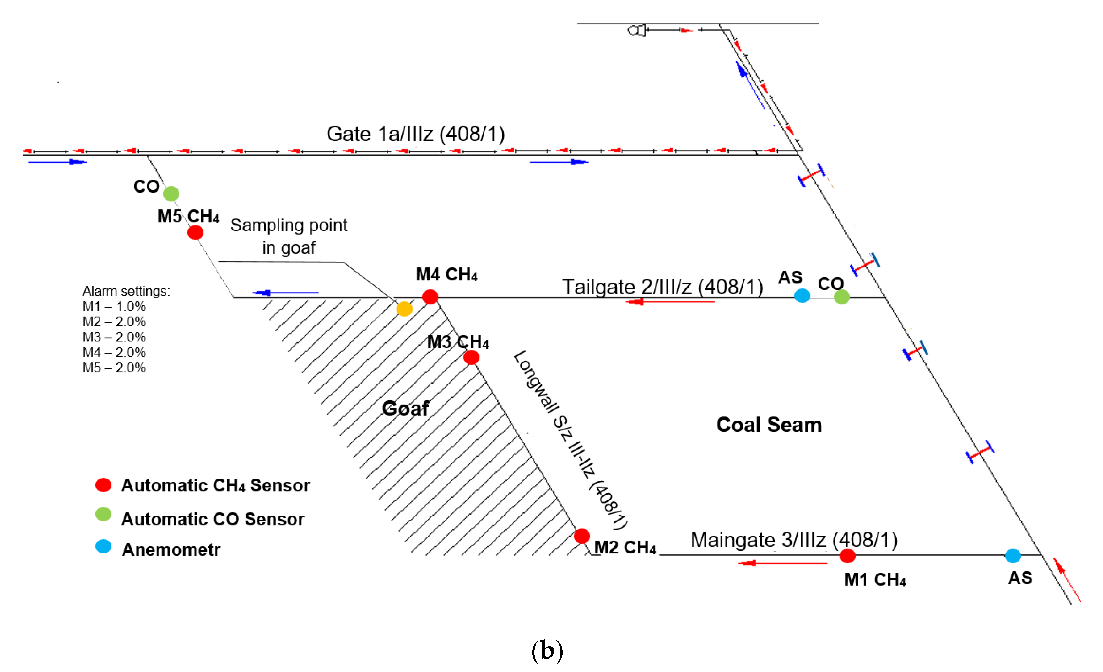
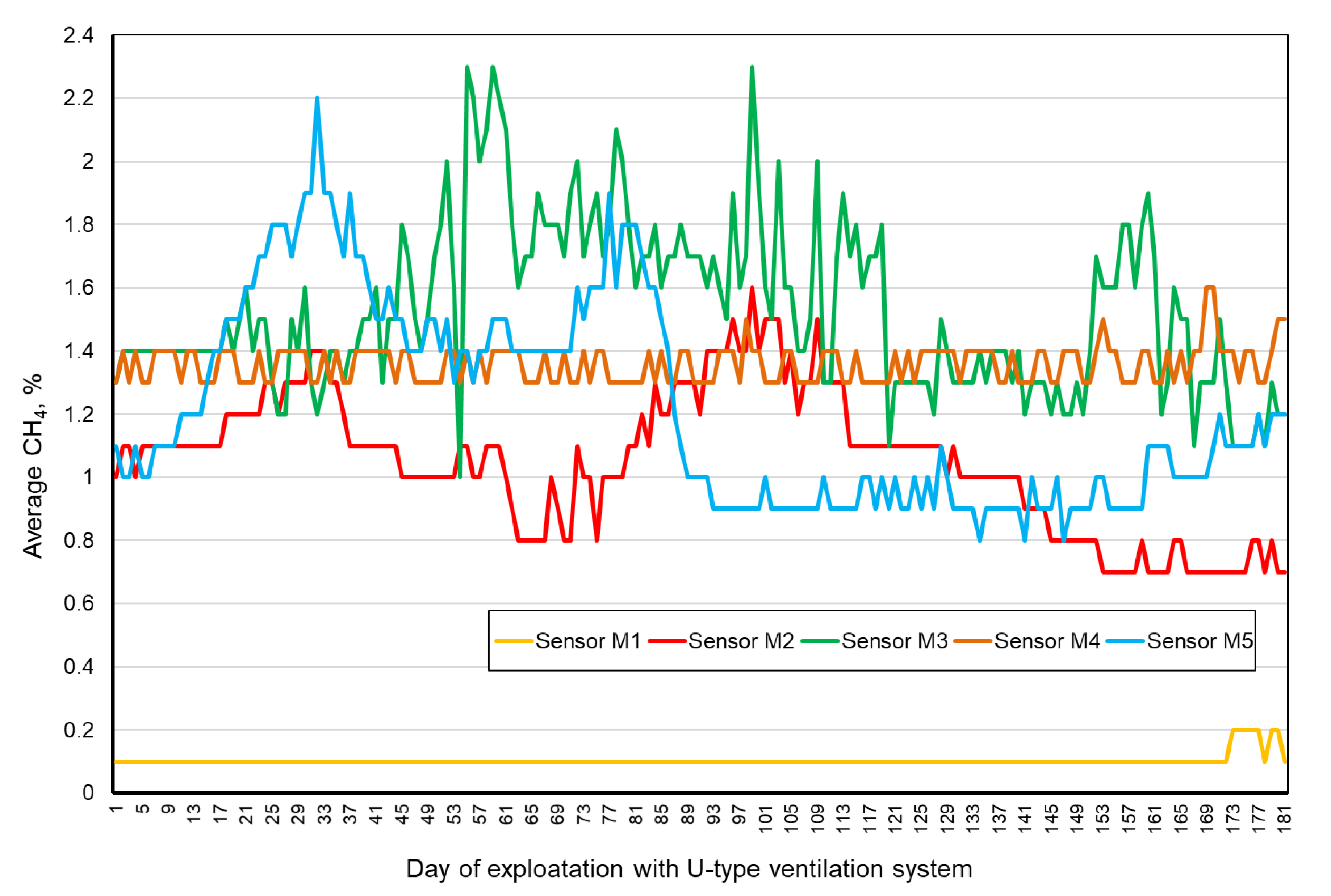
- The number of times the permitted methane concentrations were exceeded when using the U-type system was 1295, and as “only” ventilation 47 for the U-type system. The highest number of exceedances of the permissible methane concentrations when using the U-type ventilation system was recorded by the M4 sensor (776 cases), and when using the Y-type ventilation system by the M5 sensor (21 cases). There is a clear reduction in the number of exceedances, which is very important for the continuity and efficiency of the mining process;
- -
- The maximum average methane content in the ventilation air for the U-type ventilation system within the intersection of the longwall and the tailgate was 2.3%, and 1.5% for the Y-type ventilation system;
- -
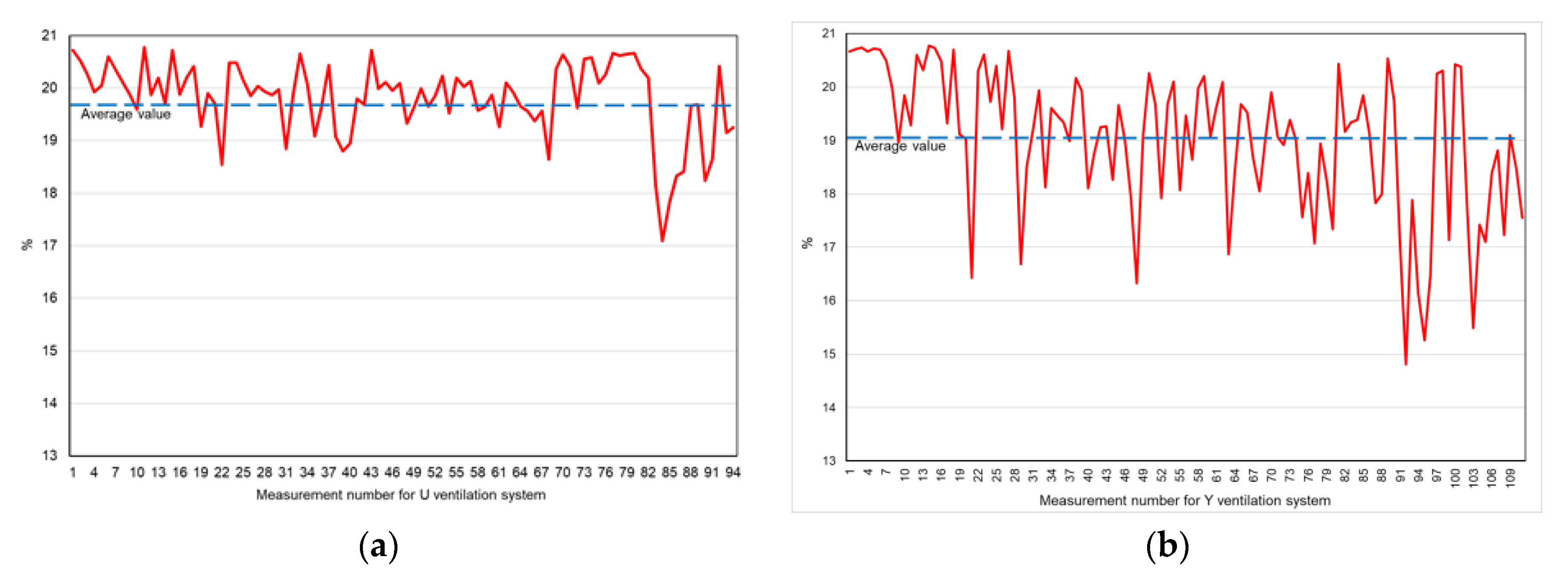
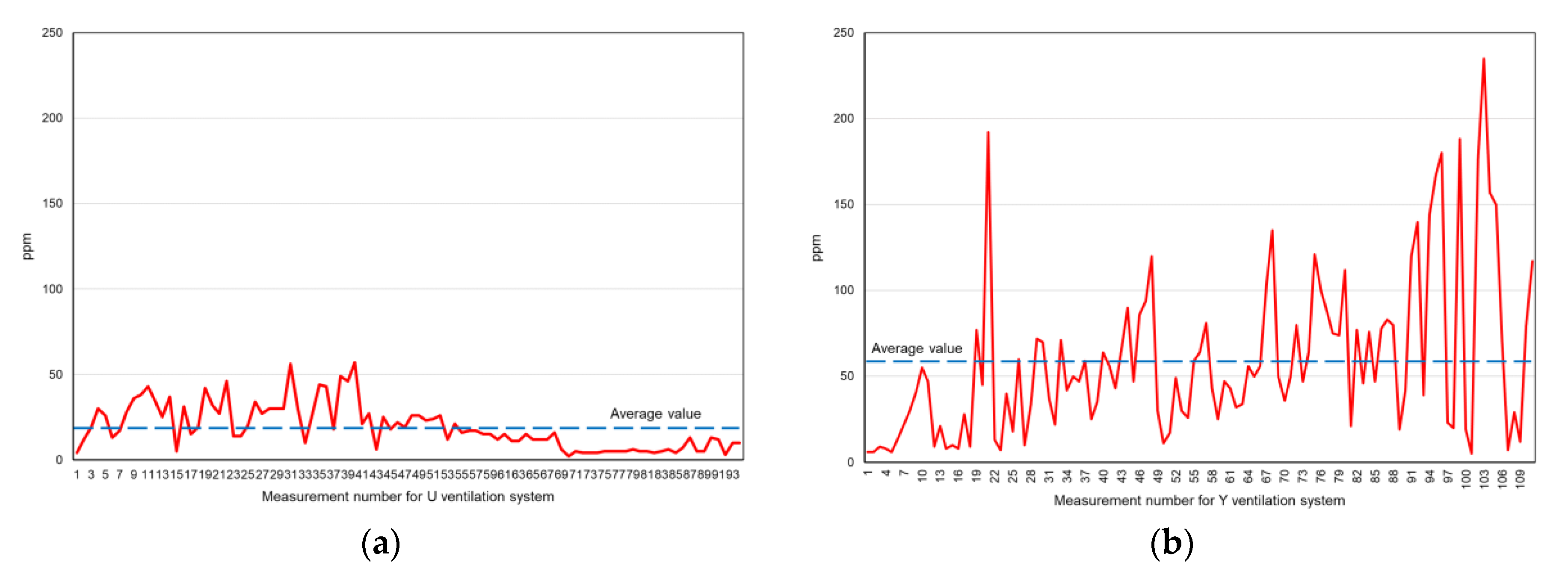
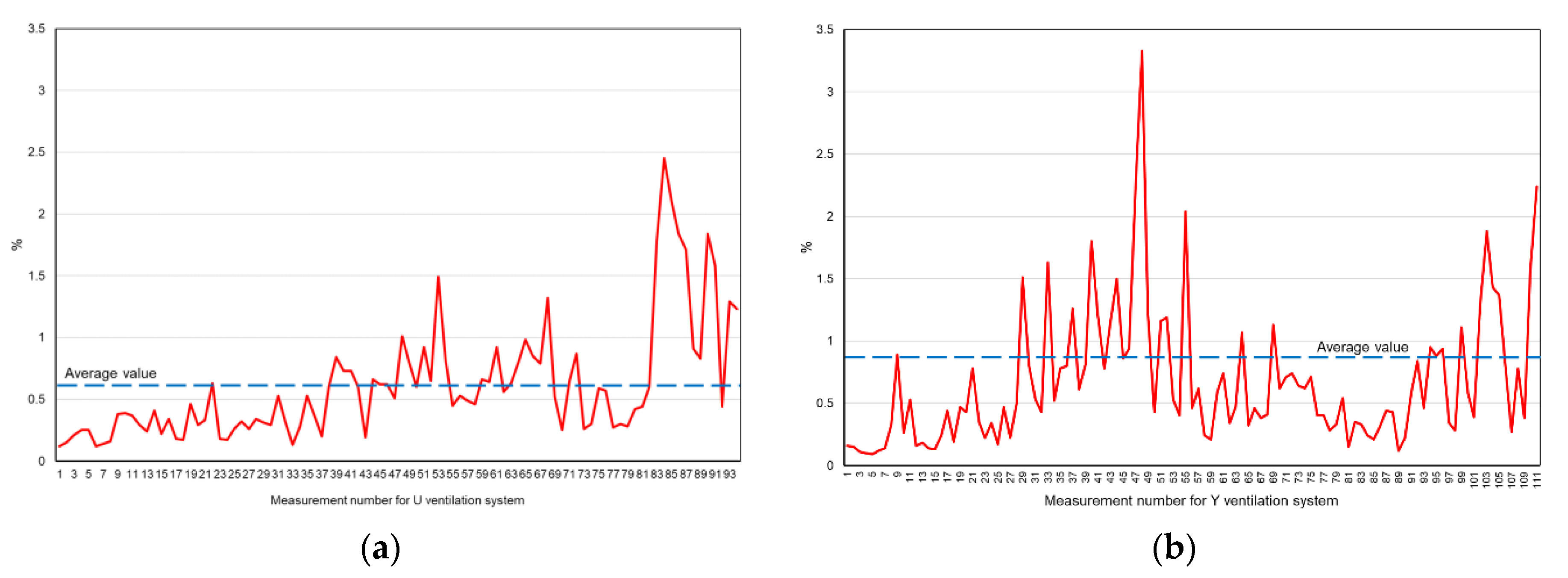
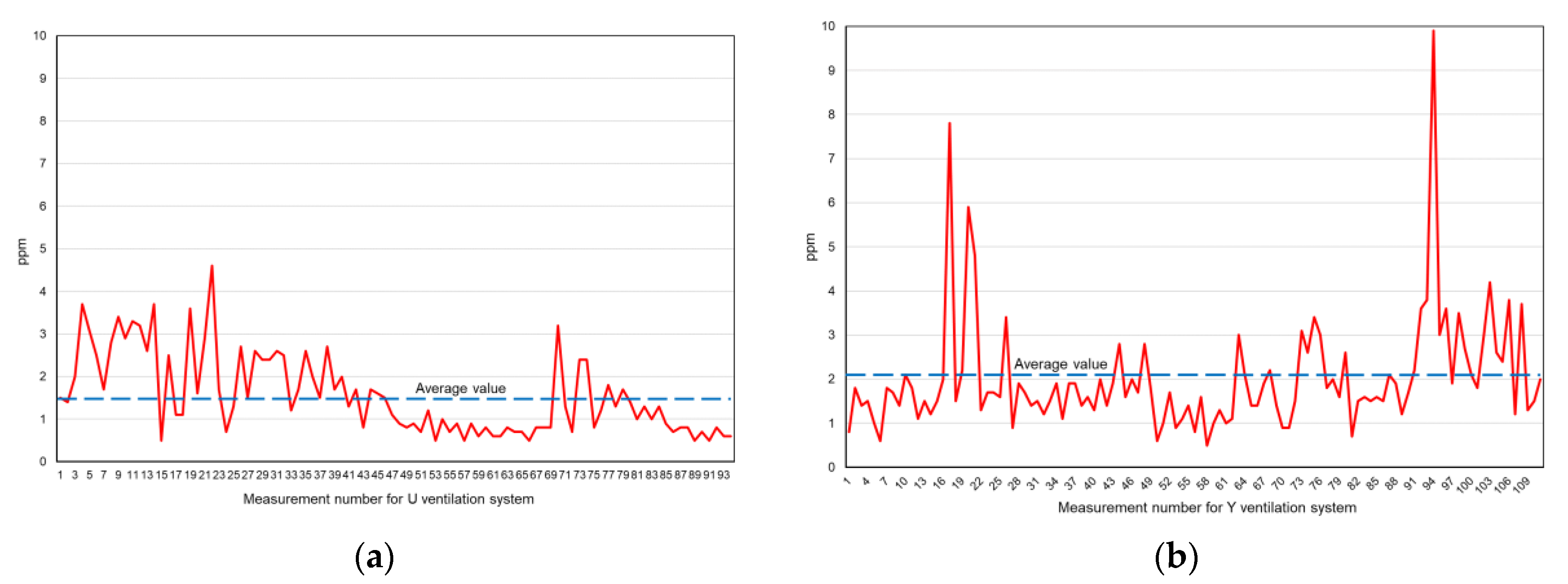
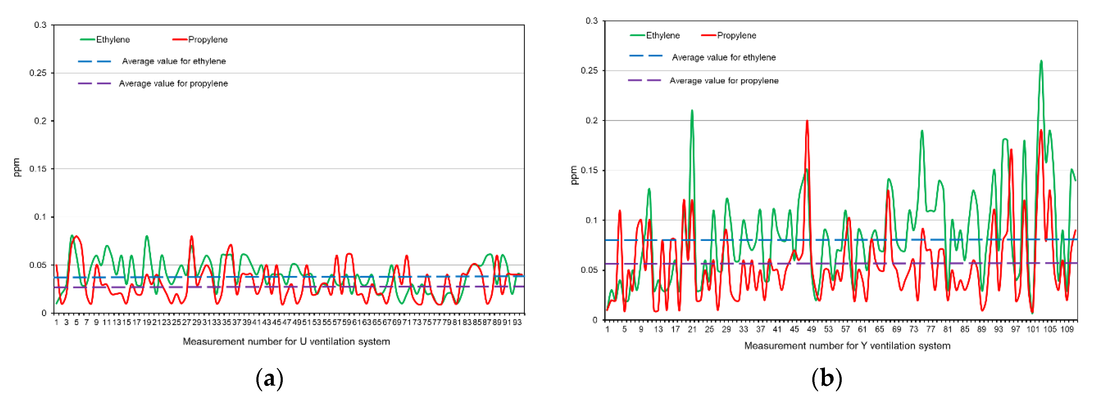
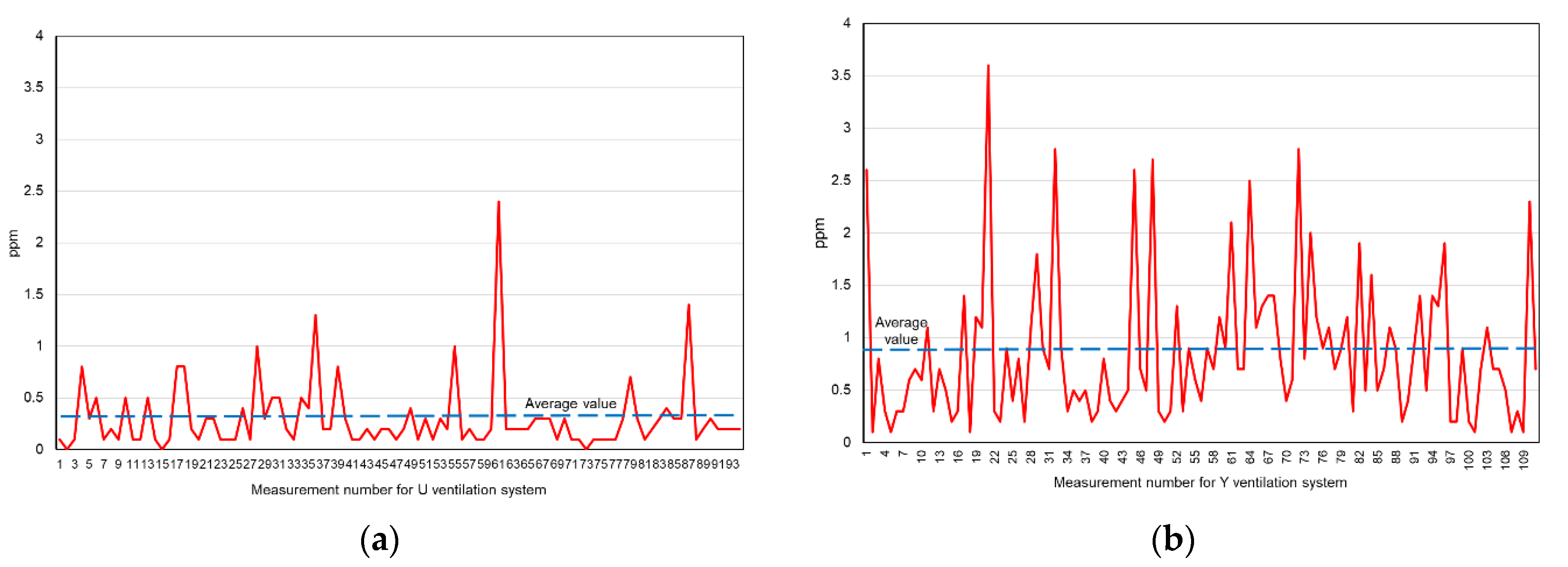
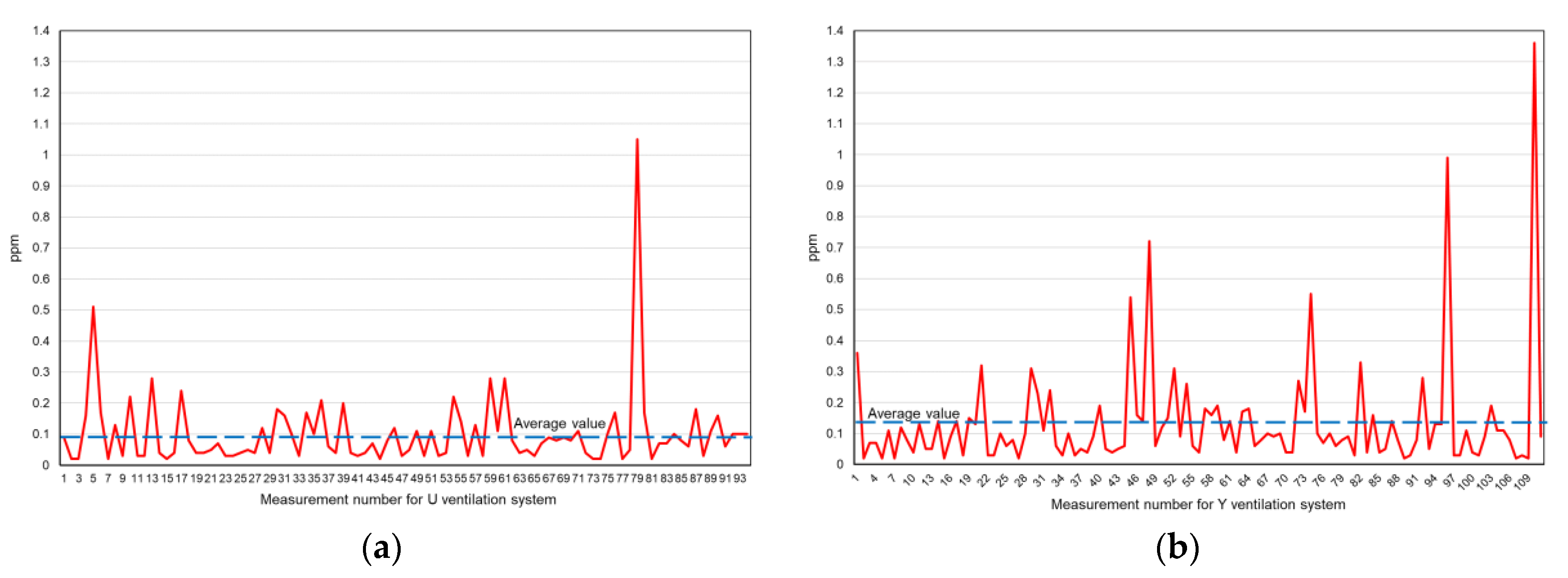
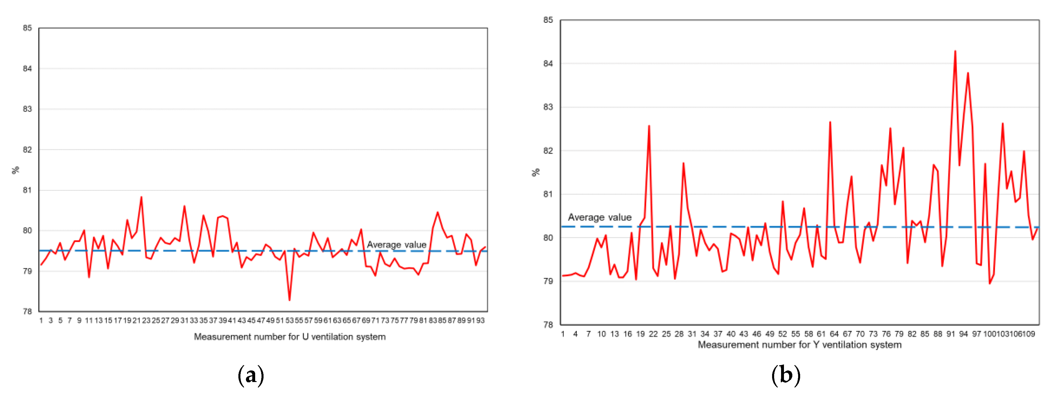
- The average concentration of gases (ethane, ethylene, propane, propylene, acetylene, carbon monoxide, carbon dioxide, hydrogen) produced during the process of oxidation and spontaneous heating of coal left in the goaf leading to its spontaneous combustion were higher for the Y-type ventilation system compared to the U-type ventilation system. At the same time, the average values of oxygen concentration in the goaf for the Y-type system were lower than for the U-type ventilation system, which indicated an intensified process of coal oxidation. The average content of carbon monoxide in the air samples taken from the goaf when using the Y-type longwall ventilation system was almost three times higher than when using the U-type system. The average content of propylene and ethylene was twice as high when using the Y-type longwall ventilation system, compared to when using the U-type system. The average oxygen content when using the Y-type ventilation system was lower than when using the U-type system; this indicates an intensified process of coal oxidation, leading to its coal spontaneous heating;
- -
- In order to reliably assess the impact of the longwall ventilation system on the level of endogenous fire hazard in the goafs, it is necessary to conduct a full analysis of the change in the concentration of fire gases as a function of time treated as fire indicators. These gases include oxygen, nitrogen, carbon monoxide, and carbon dioxide, hydrogen, and unsaturated hydrocarbons. An analysis of the concentrations of individual gases does not provide a complete picture of the endogenous fire hazard and can lead to incorrect findings.
Author Contributions
Funding
Acknowledgments
Conflicts of Interest
References
- Gui, C.; Geng, F.; Tang, J.; Niu, H.; Zhou, F.; Liu, C.; Hu, S.; Teng, H. Gas–solid two-phase flow in an underground mine with an optimized air-curtain system: A numerical study. Process Saf. Environ. Prot. 2020, 20, 137–150. [Google Scholar] [CrossRef]
- Xiu, Z.; Nie, W.; Yan, J.; Chen, D.; Cai, P.; Liu, Q.; Du, T.; Yang, B. Numerical simulation study on dust pollution characteristics and optimal dust control air flow rates during coal mine production. J. Clean. Prod. 2020, 248, 119197. [Google Scholar] [CrossRef]
- Aguado, M.; Nicieza, C. Control and prevention of gas outbursts in coal mines, Riosa–Olloniego coalfield, Spain. Int. J. Coal Geol. 2007, 69, 253–266. [Google Scholar] [CrossRef]
- Cao, S.; Liu, Y.; Wang, Y. A forecasting and forewarning model for methane hazard in working face of coal mine based on LS-SVM. J. China Univ. Min. Technol. 2008, 18, 172–176. [Google Scholar] [CrossRef]
- Kędzior, S.; Dreger, M. Methane occurrence, emissions and hazards in the Upper Silesian Coal Basin, Poland. Int. J. Coal Geol. 2019, 211, 103226. [Google Scholar] [CrossRef]
- Shi, S.; Jiang, B.; Meng, X. Assessment of gas and dust explosion in coal mines by means of fuzzy fault tree analysis. Int. J. Min. Sci. Technol. 2018, 28, 991–998. [Google Scholar] [CrossRef]
- Yang, S.; Hu, X.; Liu, W.V.; Cai, J.; Zhou, X. Spontaneous combustion influenced by surface methane drainage and its prediction by rescaled range analysis. Int. J. Min. Sci. Technol. 2018, 28, 215–221. [Google Scholar] [CrossRef]
- Yu, Y.; Bai, J.; Wang, X.; Zhang, L. Control of the surrounding rock of a goaf-side entry driving heading mining face. Sustainability 2020, 12, 2623. [Google Scholar] [CrossRef]
- Mark, C.; Gauna, M. Evaluating the risk of coal bursts in underground coal mines. Int. J. Min. Sci. Technol. 2016, 26, 47–52. [Google Scholar] [CrossRef]
- Burtan, Z.; Stasica, Z.; Rąk, Z. The influence of natural hazards of disasters on the work safety conditions in Polish coal mining in the years 2000–2016. Zesz. Nauk. Inst. Gospod. Surowcami Miner. I Energią PAN 2017, 101, 7–18. [Google Scholar]
- Burtan, Z.; Chlebowski, D.; Kapusta, M. The scale and conditions of disasters induced by the occurrence of natural hazards in the coal mining sector in Poland. Bezpieczeństwo Pr. Ochr. Środowiska Górnictwie 2018, 7, 3–11. [Google Scholar]
- Liang, K.; Liu, J.; Wang, C. The coal mine accident causation model based on the hazard theory. Procedia Eng. 2011, 26, 2199. [Google Scholar] [CrossRef]
- Ramani, R.V. Mining disasters caused and controlled by mankind: The case for coal mining and other minerals Part 1: Causes of mining disasters. Nat. Resour. Forum 1995, 19, 233–242. [Google Scholar] [CrossRef]
- Saleh, J.H.; Cummings, A.M. Safety in the mining industry and the unfinished legacy of mining accidents: Safety levers and defense-in-depth for addressing mining hazards. Saf. Sci. 2011, 49, 764–777. [Google Scholar] [CrossRef]
- Zhu, Y.; Wang, D.; Shao, Z.; Xu, C.; Zhu, X.; Qi, X.; Liu, F. A statistical analysis of coal mine fires and explosions in China. Process Saf. Environ. Protect. 2019, 121, 357–366. [Google Scholar] [CrossRef]
- Harris, J.; Kirsch, P.A.; Shi, M.; Li, J.; Gagrani, A. Comparative analysis of coal fatalities in Australia, South Africa, India, China and USA, 2006–2010. Coal Oper. Conf. 2014, 399–407. [Google Scholar]
- Brodny, J.; Tutak, M. Analysing the utilisation effectiveness of mining machines using independent data acquisition systems: A case study. Energies 2019, 12, 2505. [Google Scholar] [CrossRef]
- Karacan, C.Ö.; Olea, R.A.; Goodman, G. Geostatistical modeling of the gas emission zone and its in-place gas content for Pittsburgh-seam mines using sequential Gaussian simulation. Int. J. Coal Geol. 2012, 90, 50–71. [Google Scholar] [CrossRef]
- Hu, S.; Yang, S.; Liu, W.V.; Zhou, X.; Sun, J.; Yu, H. A methane emission control strategy in the initial mining range at a spontaneous combustion-prone longwall face: A case study in coal 15, Shigang Mine, China. J. Nat. Gas Sci. Eng. 2017, 38, 504–515. [Google Scholar] [CrossRef]
- Liang, Y.; Zhang, J.; Wang, L.; Luo, H.; Ren, T. Forecasting spontaneous combustion of coal in underground coal mines by index gases: A review. J. Loss Prev. Proc. 2019, 57, 208–222. [Google Scholar] [CrossRef]
- Ma, D.; Qin, B.; Li, L.; Gao, A.; Gao, Y. Study on the methane explosion regions induced by spontaneous combustion of coal in longwall gobs using a scaled-down experiment set-up. Fuel 2019, 254, 115547. [Google Scholar] [CrossRef]
- Ma, L.; Zou, L.; Ren, L.; Chung, Y.; Zhang, P.; Shu, C. Prediction indices and limiting parameters of coal spontaneous combustion in the Huainan mining area in China. Fuel 2020, 264, 116883. [Google Scholar] [CrossRef]
- Wen, H.; Yu, Z.; Fan, S.; Zhai, X.; Liu, W. Prediction of spontaneous combustion potential of coal in the gob area using CO extreme concentration: A case study. Combust. Sci. Technol. 2017, 189, 1713–1727. [Google Scholar] [CrossRef]
- Xia, T.; Zhou, F.; Wang, X.; Zhang, Y.; Li, Y.; Kang, J.; Liu, J. Controlling factors of symbiotic disaster between coal gas and spontaneous combustion in longwall mining gobs. Fuel 2016, 182, 886–896. [Google Scholar] [CrossRef]
- Zhai, X.; Xu, Y.; Yu, Z. Numerical analysis on the evolution of CO concentration in return corner: A case study of steady U-type ventilation working face. Numer. Heat Trans. Part A Appl. 2018, 74, 1732–1746. [Google Scholar] [CrossRef]
- Zhuo, H.; Qin, B.; Qin, Q.; Su, Z. Modeling and simulation of coal spontaneous combustion in a gob of shallow buried coal seams. Process Saf. Environ. Protect. 2019, 131, 246–254. [Google Scholar] [CrossRef]
- Sanmiquel, L.; Rossell, J.M.; Vintró, C. Study of Spanish mining accidents using data Mining techniques. Saf. Sci. 2015, 75, 49–55. [Google Scholar] [CrossRef]
- Gowrisankaran, G.; He, C.; Lutz, E.; Burgess, J. Productivity, Safety, and Regulation in Underground Coal Mining: Evidence from Disasters and Fatalities. Available online: https://www.nber.org/papers/w21129.pdf (accessed on 15 July 2020).
- Xu, Y.; Li, Z.; Zhai, X.; Yu, Z. Potential dangerous zone of coal spontaneous combustion and gas coupled hazard in goaf under mining condition. J. China Coal Soc. 2019. [Google Scholar] [CrossRef]
- Ma, L.; Guo, R.Z.; Gao, Y.; Ren, L.F.; Wei, G.M.; Li, C.H. Study on coal spontaneous combustion characteristics under methane-containing atmosphere. Combust. Sci. Technol. 2019, 191, 1456–1472. [Google Scholar] [CrossRef]
- Massanés, M.B.; Pera, L.S.; Moncunill, J.O. Ventilation management system for underground environments. Tunn. Undergr. Space Technol. 2015, 205, 516–522. [Google Scholar] [CrossRef]
- Szurgacz, D.; Tutak, M.; Brodny, J.; Sobik, L.; Zhironkina, O. The Method of Combating Coal Spontaneous Combustion Hazard in Goafs—A Case Study. Energies 2020, 13, 4538. [Google Scholar] [CrossRef]
- Su, H.T.; Zhou, F.B.; Song, X.L.; Qiang, Z.Y. Risk analysis of spontaneous coal combustion in steeply inclined longwall gobs using a scaled-down experimental set-up. Process. Saf. Environ. Prot. 2017, 111, 1–12. [Google Scholar] [CrossRef]
- Tang, M.Y.; Jiang, B.Y.; Zhang, R.Q.; Yin, Z.Q.; Dai, G.L. Numerical analysis on the influence of gas extraction on air leakage in the gob. J. Nat. Gas Sci. Eng. 2016, 33, 278–286. [Google Scholar] [CrossRef]
- Wu, J.J.; Liu, X.C. Risk assessment of underground coal fire development at regional scale. Int. J. Coal Geol. 2011, 86, 87–94. [Google Scholar] [CrossRef]
- Fernánez-Alaiz, F.; Castañón, A.M.; Gómez-Fernández, F.; Bernardo-Sánchez, A.; Bascompta, M. Analysis of the fire propagation in a sublevel coal mine. Energies 2020, 13, 3754. [Google Scholar] [CrossRef]
- Tutak, M.; Brodny, J. The impact of the strength of roof rocks on the extent of the zone with a high risk of spontaneous coal combustion for fully powered longwalls ventilated with the y-type system—A case study. Appl. Sci. 2019, 9, 5315. [Google Scholar] [CrossRef]
- Mine Ventilation Systems. Available online: http://web.mst.edu/~tien/218/lab8-systems.pdf (accessed on 15 July 2020).
- Kingery, D.S. Introduction to Mine Ventilating Principles and Practices; United States Government printing office: Washington, DC, USA, 1960.
- Szlązak, J.; Szlązak, N. Filtracja Powietrza Przez Zroby Ścian Zawałowych w Kopalniach Węgla Kamiennego; AGH Uczelniane Wydawnictwa Naukowo-Dydaktyczne: Kraków, Poland, 2005. [Google Scholar]
- Kłeczek, Z. Geomechanika Górnicza; Śląskie Wydawnictwo Techniczne: Katowice, Poland, 1994. [Google Scholar]
- Palchik, V. Formation of fractured zones in overburden due to longwall mining. J. Environ. Geol. 2003, 44, 28. [Google Scholar] [CrossRef]
- Brune, J.; Grubb, J.; Bogin, G.; Zipf, R.; Marts, J.; Gilmore, R.; Lolon, S.; Saki, S. A Critical Look at Longwall Bleeder Ventilation. Available online: https://www.semanticscholar.org/paper/A-Critical-Look-at-Longwall-Bleeder-Ventilation-Brune-Grubb/bb0d5819f17103a1e9faddb336930441510fc537 (accessed on 15 August 2020).
- Chen, P.; Zhang, L.; Zou, D. Study of three-dimensional distribution of permeability in gob based on o-shape circle theory. Min. Saf. Environ. Prot. 2015, 42, 38–41. [Google Scholar]
- Das, S.K. Observations and classification of roof strata behaviour over longwall coal mining panels in India. Int. J. Rock Mech. Min. Sci. 2000, 37, 585–597. [Google Scholar] [CrossRef]
- Wang, K.; Tang, H.; Miao, Y.; Liu, D. Research on complex air leakage method to prevent coal spontaneous combustion in longwall goaf. PLoS ONE 2019, 14, e0213101. [Google Scholar] [CrossRef]
- Gilman, A.; Beckie, R. Flow of coal-bed methane to a gallery. Transp. Porous Media 2000, 41, 1–16. [Google Scholar] [CrossRef]
- Valliappan, S.; Wohua, Z. Numerical modelling of methane gas migration in dry coal seams. Int. J. Numer. Anal. Methods Geomech. 1996, 20, 571–593. [Google Scholar] [CrossRef]
- Barker-Read, G.R.; Radchenko, S.A. Methane emission from coal and associated strata samples. Int. Min. Ceol. Eng. 1989, 7, 101–126. [Google Scholar] [CrossRef]
- Bertrard, C.; Bruyet, B.; Gunther, J. Determination of desorb able gas concentration of coal (direct method). Int. Rock Mech. Min. Sci. 1970, 7, 43–65. [Google Scholar] [CrossRef]
- Jolly, D.C.; Morris, H.; Hinsley, F.B. An investigation into the relationship between the methane sorption capacity of coal and gas pressure. Min. Eng. 1968, 127, 539–548. [Google Scholar]
- Hildenbrand, A.; Krooss, B.M.; Busch, A.; Gaschnitz, R. Evolution of methane sorption capacity of coal seams as a function of burial history—A case study from the Campine Basin, NE Belgium. Int. J. Coal Geol. 2006, 66, 179–203. [Google Scholar] [CrossRef]
- Kam, A.Y.; Hixson, A.N.; Perlmutter, D.D. The oxidation of bituminous coal—I Development of a mathematical model. Chem. Eng. Sci. 1976, 31, 815–819. [Google Scholar] [CrossRef]
- Kam, A.Y.; Hixson, A.N.; Perlmutter, D.D. The oxidation of bituminous coal—II experimental kinetics and interpretation. Chem. Eng. Sci. 1976, 31, 821–834. [Google Scholar] [CrossRef]
- Lu, P.; Liao, G.X.; Sun, J.H.; Li, P.D. Experimental research on index gas of the coal spontaneous at low-temperature stage. J. Loss Prevent. Proc. 2004, 17, 243–247. [Google Scholar] [CrossRef]
- Xiao, Y.; Wang, Z.P.; Ma, L.; Ziai, X.W. Research on correspondence relationship between coal spontaneous combustion index gas and feature temperature. Coal Sci. Technol. 2008, 36, 47–51. [Google Scholar]
- Adamus, A.; Sancer, J.; Guranova, P.; Zubicek, V. An investigation of the factors associated with interpretation of mine atmosphere for spontaneous combustion in coal mines. Fuel Process. Technol. 2011, 92, 663–670. [Google Scholar] [CrossRef]
- Arisoy, A.; Beamish, B. Mutual effects of pyrite and moisture on coal self-heating rates and reaction rate data for pyrite oxidation. Fuel 2015, 139, 107–114. [Google Scholar] [CrossRef]
- Dai, G.L. Study on the gaseous products in coal oxidation at low temperature. Coal Mine Saf. 2007, 1, 1–4. [Google Scholar]
- Chamberlain, E.A.C.; Barrass, G.; Thirlaway, J.T. Gases evolved and possible reactions during low-temperature oxidation of coal. Fuel 1976, 55, 217–223. [Google Scholar] [CrossRef]
- Chamberlin, E.C.A.; Hall, D.A.; Thirlway, J.T. The ambient temperature oxidation of coal in relation to early detection of spontaneous heating. Min. Eng. 1970, 130, 1–16. [Google Scholar]
- Manohar Rao, A.; Ramalingeswarudu, S.; Venkateswarlu, G. Planning of ventilation requirements for deep mechanised long wall faces—A case study of Adriyala Longwall Project of the Singareni Collieries Company Limited (SCCL). Procedia Earth Planet. Sci. 2015, 11, 548–556. [Google Scholar]
- Gilles, S.; Wu, H. Australian Longwall Panel Ventilation Practices. Available online: https://ro.uow.edu.au/cgi/viewcontent.cgi?referer=https://www.google.com/&httpsredir=1&article=2114&context=coal (accessed on 15 July 2020).
- Mayes, T.; Gillies, A. An Analysis of Current Australian Longwall Ventilation Methods. In Proceedings of the Seventh International Mine Ventilation Congress, Cracow, Poland, 17–22 June 2001; Wasilewski, S., Ed.; Polish Academy of Sciences: Krakow, Pland, 2001; pp. 793–800. Available online: http://www.gwmt.com.au/Papers/2001/2001%20-%20June%20-%207IMVC%20LW%20ventilation.pdf (accessed on 15 July 2020).
- Krog, R. Critical Analysis of Longwall Ventilation Systems and Removal of Methane. Available online: https://researchrepository.wvu.edu/cgi/viewcontent.cgi?article=7057&context=etd (accessed on 15 July 2020).
- Wang, Z.; Ren, T.; Ma, L.; Zhang, J. Investigations of ventilation airflow characteristics on a longwall face—A computational approach. Energies 2018, 11, 1564. [Google Scholar] [CrossRef]
- Yuan, L.; Smith, A. The effect of ventilation on spontaneous heating of coal. J. Loss Prev. Process. Ind. 2012, 25, 131–137. [Google Scholar] [CrossRef]
- Diamond, W.P.; Garcia, F. Prediction of Longwall Methane Emissions: An Evaluation of the Influence of Mining Practices on Gas Emissions and Methane Control Systems; Report of Investigations No. 9649; National Institute for Occupational Safety and Health: Pittsburgh, PA, USA, 1999. Available online: https://www.cdc.gov/niosh/mining/UserFiles/works/pdfs/ri9649.pdf (accessed on 15 July 2020).
- Wang, Z.; Ren, T.; Zhang, J. Numerical investigations of airflow patterns on a longwall face. Int. J. Oil Gas. Coal Technol. 2020, 24, 321–344. [Google Scholar] [CrossRef]
- Karacan, C.O. Modeling and prediction of ventilation methane emissions of U.S. longwall mines using supervised artificial neural networks. Int. J. Coal Geol. 2008, 73, 371–387. [Google Scholar] [CrossRef]
- Zhang, P. Numerical simulation of methane delivery law in U type ventilation work face gob. Energy Proced. 2012, 14, 632–636. [Google Scholar] [CrossRef][Green Version]
- Tutak, M.; Brodny, J. Analysis of the impact of auxiliary ventilation equipment on the distribution and concentration of methane in the Tailgate. Energies 2018, 11, 3076. [Google Scholar] [CrossRef]
- Tutak, M.; Brodny, J. Impact of type of the roof rocks on location and range of endogenous fires particular hazard zone by in goaf with caving. EPJ Web Conf. 2018, 29, 00005. [Google Scholar] [CrossRef]
- Lu, Y.; Qin, B. Identification and control of spontaneous combustion of coal pillars: A case study in the Qianyingzi Mine, China. Nat. Hazards 2015, 75, 2683–2697. [Google Scholar] [CrossRef]
- Su, H.T.; Zhou, F.B.; Song, X.L.; Shi, B.B.; Sun, S.H. Risk analysis of coal self-ignition in longwall gob: A modeling study on three-dimensional hazard zones. Fire Saf. J. 2016, 83, 54–65. [Google Scholar]
- Wang, Y.; Zhang, X.; Sugai, Y.; Sasaki, K. A study on preventing spontaneous combustion of residual coal in a coal mine goaf. J. Geol. Res. 2015, 2015, 712349. [Google Scholar] [CrossRef]
- Pan, R.; Cheng, Y.; Yu, M.; Lu, C.; Yang, K. New technological partition for ‘three zones’ spontaneous coal combustion in goaf. Int. J. Min. Sci. Technol. 2013, 23, 489–493. [Google Scholar] [CrossRef]
- He, X.; Zhang, R.; Pei, X.; Sun, Y.; Tong, B.; Huang, H. Numerical simulation for determining three zones in the goaf at a fully-mechanized coal face. J. China Univ. Min. Technol. 2008, 18, 199–203. [Google Scholar] [CrossRef]
- Huang, Z.A.; Ma, Z.Z.; Song, S.Y.; Yang, R.; Gao, Y.K.; Zhang, Y.H. Study on the influence of periodic weighting on the spontaneous combustion “three-zone” in a gob. J. Loss Prev. Process Ind. 2018, 5, 480–491. [Google Scholar] [CrossRef]
- Taraba, B.; Slovak, V.; Michalec, Z.; Chura, J.; Taufer, A. Development of oxidation heat of the coal left in the mined-out area of a longwall face: Modelling using the fluent software. J. Min. Metall. B Metall. 2008, 44, 73–81. [Google Scholar] [CrossRef]
- Taraba, B.; Michalec, Z. Effect of longwall face advance rate on spontaneous heating process in the gob area—CFD modelling. Fuel 2011, 90, 2790–2797. [Google Scholar] [CrossRef]
- Yuan, L.; Smith, A.C. Numerical study on effects of coal properties on spontaneous heating in longwall gob areas. Fuel 2008, 87, 3409–3419. [Google Scholar] [CrossRef]
- Liu, W.; Qin, Y. Multi-physics coupling model of coal spontaneous combustion in longwall gob area based on moving coordinates. Fuel 2017, 188, 553–566. [Google Scholar] [CrossRef]
- Chen, X.; Li, L.; Guo, Z.; Chang, T. Evolution characteristics of spontaneous combustion in three zones of the goaf when using the cutting roof and release pressure technique. Energy Sci. Eng. 2019, 7, 710–720. [Google Scholar] [CrossRef]
- Xu, Y.; Li, Z.; Liu, H.; Zhai, X.; Li, R.; Song, P.; Jia, M. A model for assessing the compound risk represented by spontaneous coal combustion and methane emission in a gob. J. Clean. Prod. 2020, 273, 122925. [Google Scholar] [CrossRef]
- Brune, J.; Saki, S. Prevention of gob ignitions and explosions in longwall mining using dynamic seals. Int. J. Min. Sci. Technol. 2017, 27, 999–1003. [Google Scholar] [CrossRef]
- Li, L.; Qin, B.; Ma, D.; Zhuo, H.; Liang, H.; Gao, A. Unique spatial methane distribution caused by spontaneous coal combustion in coal mine goafs: An experimental study. Process Saf. Environ. Prot. 2018, 116, 199–207. [Google Scholar] [CrossRef]
- Zhang, Y.; Zhang, X.; Li, C.; Liu, C.; Wang, Z. Methane moving law with long gas extraction holes in goaf. Procedia Eng. 2011, 26, 357–365. [Google Scholar] [CrossRef][Green Version]
- Zmarzły, M.; Trzaskalik, P. Comparative analysis of methane concentration near the junction of the longwall and top road. Manag. Syst. Prod. Eng. 2019, 207, 166–173. [Google Scholar] [CrossRef]
- Polska Grupa Górnicza. Available online: https://www.pgg.pl/o-firmie/oddzialy/kz1 (accessed on 15 July 2020).
- Ordinance of the Minister of Energy on Detailed Requirements for Conducting Underground Mining Operations of 23 August 2019 (Journal of Laws of 2016, No. 2017, Item 1118, as Amended). Available online: http://isap.sejm.gov.pl/isap.nsf/DocDetails.xsp?id=WDU20170001118 (accessed on 15 July 2020).
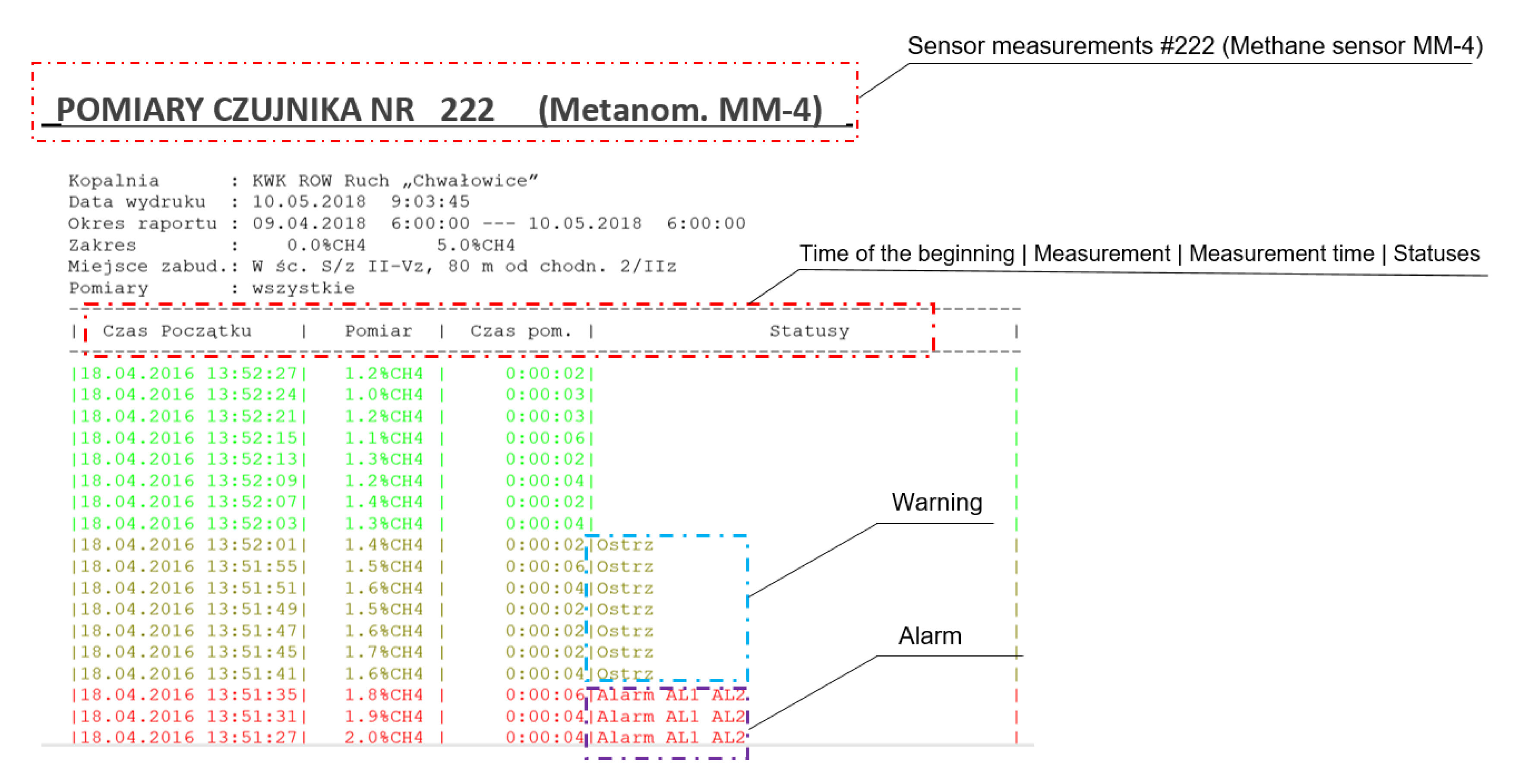
- Bojko, B.; Mirek, G. Connecting mining monitoring system of environmental parameters with alarming system. Pomiary Autom. Robot. 2010, 2, 572–578. [Google Scholar]


| Type of Rock | Zone | Rc, MPa | Soakability | Separability | Density, g/cm3 |
|---|---|---|---|---|---|
| sandstone | roof | 41.6 | 0.8–1.0 | block | 2.65 |
| shale | roof | 26.6 | 0.6 | block | 2.50 |
| coal (seam 408/1) | seam | 17.5 | - | - | 1.28 |
| shale | floor | 31.7 | 0.6 | block | 2.56 |
| Petrographic | Content, % |
|---|---|
| Vitrinite | 60–90 |
| Exinite | 5–20 |
| Inertinite | 5–25 |
| Liptinite | 5–8 |
| Sulphides | 1 |
| Clay materials | 1 |
| Mineral matter | 2–30 |
| Category of Methane Release Hazard | Description |
|---|---|
| I | Category I methane release hazard includes the developed seam or its part if the quantity of methane of natural origin contained in a unit of weight in the depth of the body of coal, referred to as “methane carrying capacity”, is between 0.1 and 2.5 m3/Mg of dry ash-free coal. |
| II | Category II methane release hazard includes the developed seam or its part if the methane carrying capacity is greater than 2.5 m3/Mg but not greater than 4.5 m3/Mg of dry ash-free coal. |
| III | Category III methane release hazard includes the developed seam or its part if the methane carrying capacity is greater than 4.5 m3/Mg but not greater than 8 m3/Mg of dry ash-free coal. |
| IV | Category IV methane release hazard includes the developed seam or its part if the methane carrying capacity is greater than 8 m3/Mg of dry ash-free coal or if there is a sudden methane release or methane and rock outburst. |
| Sensor | Mean | Median | Min | Max | 10th Percentile | 90th Percentile | Stand. Deviation | Variation Coefficient | Skewness | Kurtosis |
|---|---|---|---|---|---|---|---|---|---|---|
| M1 | 0.1 | 0.1 | 0.1 | 0.2 | 0.1 | 0.2 | 0.0 | 32.4 | 1.7 | 0.9 |
| M2 | 0.9 | 1.0 | 0.6 | 1.6 | 0.6 | 1.3 | 0.3 | 29.0 | 0.3 | −1.1 |
| M3 | 1.6 | 1.5 | 1.0 | 2.3 | 1.2 | 1.8 | 0.3 | 17.7 | 0.7 | 0.0 |
| M4 | 1.4 | 1.4 | 1.3 | 1.6 | 1.3 | 1.4 | 0.1 | 4.3 | 0.7 | 0.9 |
| M5 | 1.2 | 1.1 | 0.8 | 2.2 | 0.9 | 1.6 | 0.3 | 23.7 | 1.0 | 0.3 |
| Sensor | No. of Exceedances, U-Type |
|---|---|
| M1 | 0 |
| M2 | 40 |
| M3 | 423 |
| M4 | 776 |
| M5 | 56 |
| Sensor | Mean | Median | Min | Max | 10th Percentile | 90th Percentile | Stand. Deviation | Coefficient of Variation | Skewness | Kurtosis |
|---|---|---|---|---|---|---|---|---|---|---|
| M1 | 0.20 | 0.20 | 0.10 | 0.30 | 0.10 | 0.20 | 0.04 | 22.27 | −1.30 | 0.83 |
| M2 | 0.80 | 0.70 | 0.60 | 1.20 | 0.60 | 1.00 | 0.15 | 18.95 | 1.12 | 0.36 |
| M3 | 1.30 | 1.30 | 1.20 | 1.50 | 1.30 | 1.40 | 0.05 | 4.09 | 0.23 | −0.73 |
| M4 | 1.10 | 1.10 | 1.00 | 1.40 | 1.10 | 1.20 | 0.08 | 7.10 | 1.36 | 2.31 |
| M5 | 0.80 | 0.80 | 0.60 | 1.40 | 0.70 | 1.10 | 0.19 | 22.63 | 0.83 | −0.50 |
| Sensor | No. of Exceedances, Y-Type |
|---|---|
| M1 | 0 |
| M2 | 0 |
| M3 | 17 |
| M4 | 9 |
| M5 | 21 |
| Variable | Ventilation System | |
|---|---|---|
| U | Y | |
| Absolute methane content, m3/min | 34.37 | 35.46 |
| Ventilation methane content, m3/min | 15.24 | 13.15 |
| Methane drainage m3/min | 19.13 | 22.31 |
| Variable | Absolute Methane Content | Ventilation Methane Content | Methane Drainage |
|---|---|---|---|
| Absolute methane content | 1.00 | 0.85 | 0.97 |
| Ventilation methane content | 0.85 | 1.00 | 0.69 |
| Methane drainage | 0.97 | 0.69 | 1.00 |
| Variable | U-Type Ventilation System | Y-Type Ventilation System | ||||
|---|---|---|---|---|---|---|
| Absolute Methane Content | Ventilation Methane Content | Methane Drainage | Absolute Methane Content | Ventilation Methane Content | Methane Drainage | |
| Absolute methane content | 1.00 | 0.62 | 0.99 | 1.00 | 0.96 | 0.99 |
| Ventilation methane content | 0.62 | 1.00 | 0.52 | 0.96 | 1.00 | 0.91 |
| Methane drainage | 0.99 | 0.52 | 1.00 | 0.99 | 0.91 | 1.00 |
| Tested Gas | Mean | Median | Min | Max | 90th Percentile | Stand. Deviation | Coefficient of Variation | |||||||
|---|---|---|---|---|---|---|---|---|---|---|---|---|---|---|
| Ventilation System | ||||||||||||||
| U | Y | U | Y | U | Y | U | Y | U | Y | U | Y | U | Y | |
| Ethane | 0.30 | 0.86 | 0.20 | 0.70 | 0.00 | 0.10 | 2.40 | 3.60 | 0.70 | 1.90 | 0.34 | 0.70 | 112.30 | 80.61 |
| Ethylene | 0.04 | 0.08 | 0.04 | 0.08 | 0.01 | 0.01 | 0.12 | 0.26 | 0.06 | 0.15 | 0.02 | 0.05 | 45.98 | 57.04 |
| Propane | 0.10 | 0.13 | 0.07 | 0.09 | 0.02 | 0.02 | 1.05 | 1.36 | 0.20 | 0.27 | 0.13 | 0.18 | 123.32 | 135.04 |
| Propylene | 0.03 | 0.06 | 0.03 | 0.05 | 0.01 | 0.01 | 0.08 | 0.20 | 0.06 | 0.10 | 0.02 | 0.04 | 57.12 | 66.46 |
| Acetylene | 0.002 | 0.003 | 0.002 | 0.002 | 0.001 | 0.001 | 0.01 | 0.013 | 0.01 | 0.01 | 0.34 | 0.36 | 120.35 | 66.49 |
| Carbon monoxide | 19.18 | 59.65 | 16.00 | 47.00 | 2.00 | 5.00 | 57.00 | 235.00 | 38.00 | 121.00 | 13.18 | 47.64 | 68.74 | 79.86 |
| Oxygen | 19.81 | 19.00 | 19.92 | 19.21 | 17.09 | 14.81 | 20.78 | 20.77 | 20.62 | 20.60 | 0.70 | 1.34 | 3.56 | 7.06 |
| Nitrogen | 79.57 | 80.27 | 79.53 | 80.01 | 78.28 | 78.95 | 80.83 | 84.29 | 80.06 | 81.72 | 0.41 | 1.09 | 0.52 | 1.36 |
| Carbon dioxide | 0.61 | 0.68 | 0.51 | 0.49 | 0.12 | 0.09 | 2.45 | 3.33 | 1.29 | 1.43 | 0.47 | 0.56 | 76.67 | 82.38 |
| Hydrogen | 1.57 | 2.02 | 1.30 | 1.70 | 0.50 | 0.50 | 4.60 | 9.90 | 2.90 | 3.40 | 0.94 | 1.31 | 59.83 | 64.78 |
© 2020 by the authors. Licensee MDPI, Basel, Switzerland. This article is an open access article distributed under the terms and conditions of the Creative Commons Attribution (CC BY) license (http://creativecommons.org/licenses/by/4.0/).
Share and Cite
Tutak, M.; Brodny, J.; Szurgacz, D.; Sobik, L.; Zhironkin, S. The Impact of the Ventilation System on the Methane Release Hazard and Spontaneous Combustion of Coal in the Area of Exploitation—A Case Study. Energies 2020, 13, 4891. https://doi.org/10.3390/en13184891
Tutak M, Brodny J, Szurgacz D, Sobik L, Zhironkin S. The Impact of the Ventilation System on the Methane Release Hazard and Spontaneous Combustion of Coal in the Area of Exploitation—A Case Study. Energies. 2020; 13(18):4891. https://doi.org/10.3390/en13184891
Chicago/Turabian StyleTutak, Magdalena, Jarosław Brodny, Dawid Szurgacz, Leszek Sobik, and Sergey Zhironkin. 2020. "The Impact of the Ventilation System on the Methane Release Hazard and Spontaneous Combustion of Coal in the Area of Exploitation—A Case Study" Energies 13, no. 18: 4891. https://doi.org/10.3390/en13184891
APA StyleTutak, M., Brodny, J., Szurgacz, D., Sobik, L., & Zhironkin, S. (2020). The Impact of the Ventilation System on the Methane Release Hazard and Spontaneous Combustion of Coal in the Area of Exploitation—A Case Study. Energies, 13(18), 4891. https://doi.org/10.3390/en13184891