Article

Mechanical Integrity Assessment of Two-Side Etched Type Printed Circuit Heat Exchanger with Additional Elliptical Channel

Department of Mechanical and Control Engineering, Handong Global University, Pohang 37554, Korea
*
Author to whom correspondence should be addressed.
Energies 2020, 13(18), 4711; https://doi.org/10.3390/en13184711
Submission received: 17 July 2020 / Revised: 2 September 2020 / Accepted: 3 September 2020 / Published: 10 September 2020
(This article belongs to the Special Issue Modelling of Thermal and Energy Systems)

Abstract

:
Printed circuit heat exchangers (PCHEs) are often subject to high pressure and temperature difference between the hot and cold channels which may cause a mechanical integrity problem. A conventional plate heat exchanger where the channel geometries are semi-circular and etched at one side of the stacked plate is a common design in the market. However, the sharp edge tip channel may cause high stress intensity. Double-faced type PCHE appears with the promising ability to reduce the stress intensity and stress concentration factor. Finite element analysis simulation has been conducted to observe the mechanical integrity of double-etched printed circuit heat exchanger design. The application of an additional ellipse upper channel helps the stress intensity decrease in the proposed PCHE channel. Five different cases were simulated in this study. The simulation shows that the stress intensity was reduced up to 24% with the increase in additional elliptical channel radius. Besides that, the horizontal offset channels configuration was also investigated in this study. Simulation results show that the maximum stress intensity of 2.5 mm offset configuration is 9% lower compared to the maximum stress intensity of 0 mm offset. This work proposed an additional elliptical upper channel with a 2.5 mm offset configuration as an optimum design.

1. Introduction

A heat exchanger is a device that can exchange heat between two fluids at different temperatures without mixing [1,2]. In industry, the heat exchanger plays a critical role especially in heat-based power such as nuclear power. Practically, shell-and-tube heat exchanger is the most popular in industry. However, the printed circuit heat exchanger (PCHE) is now widely developed due to several promising aspects, such as a large area density and good pressure and temperature capabilities [3,4,5]. The development of highly efficient PCHE is important, which is strongly related to economy and safety aspects. In many cases, PCHE may be working at a high temperature and pressure [6]. This means that safety is an important feature of PCHE because some critical issues may occur under high temperature and pressure conditions. For example, Rakesh and Anand found thermal stress to be more dominant than pressure cycle stress due to the higher temperature gradient [7].
Many studies have been conducted to investigate thermal–hydraulic performance of PCHE. Mylavarapu et al. studied the thermal–hydraulic performance of PCHE which contains helium as the fluid [8]. The thermal hydraulic performance of a PCHE which has a longitudinal corrugation flow channel was studied by Kim et al. [9]. Sung and Lee conducted a study about the tangled channel heat PCHE for thermoelectric power generation [10]. These studies show that the development of a cross-section shape may be able to enhance the thermal–hydraulic performance.
Besides the thermal–hydraulic performance study, mechanical integrity study is also important in PCHE development. Lee and Lee [11] conducted a study about the structural assessment of a sodium and SCO2 zigzag channel by calculating the temperature and stress value. They found that the maximum stresses occurred at the channel tips which are the sharp corner of the semi-circular flow cross-section shape. Song et al. also conducted a study about the structural integrity evaluation of a lab-scale intermediate PCHE of very-high temperature reactor (VHTR). Under the test condition, the maximum Tresca stress was far below the allowable stress limit [12]. Armanto and Lee conducted a study about the mechanical integrity analysis of a PCHE with channel misalignment. This study also shows high-stress intensity at the tip edge of PCHE channels [13]. The phenomenon where the stress is shown high at the tip has also been observed at the nanoscale. Winter et al. [14] conducted a study which shows that the different pore shape and pattern will cause stress accumulation inside the structure and may lead to failure. Vo et al. [15] investigated the impact of nanopores and porosity on the mechanical properties of amorphous silica (a-SiO2). Simulation results shows that high stress concentration occurs at the top and bottom of the pore.
A double-faced heat exchanger comes with a promising ability. Unlike the conventional plate heat exchanger where the channel geometries are semi-circle and etched at one side of the stacked plate, this double-faced PCHE has two faces on one plate. During the fabrication process, the metal stacked layer will be etched on two faces and after that, they will be stacked together through the diffusion bonding process. The shape of two-etched sides can be different or like each other. Usually, in double-faced PCHE, one side is the main channel while another face can be an additional upper channel. One of the reasons for double-faced application is to enhance the heat transfer by enlarging the fluid flow cross-section area. By considering an additional upper channel by etching two sides of one stacking plate, the flow cross-section area can be larger. Another reason is that the double-faced PCHE can reduce the friction as mentioned by Lee et al. [16].
There are several studies conducted about double-etched circular channel PCHE. Ma et al. [17] considered a double-etched PCHE at the high temperature of 900 °C and a high pressure above 7 MPa. One side of the stacked plate is considered as a semi-circle flow channel while another side is as an elliptical additional upper channel. A thermo-hydraulic performance of the proposed PCHE channel design was studied numerically. Based on the study, it was found that the additional elliptical upper channel can improve the heat transfer of PCHE and increase the pressure drop simultaneously. It was found that the Nusselt number was increased by 7−17% with a 0.234 mm additional upper channel, while the fanning factor increased by 3−5%. Lee and Kim [18] investigated the performance of a zigzag printed circuit heat exchanger with various channel shapes. Four shapes of channel cross-section were investigated such as semi-circle, rectangle, trapezoid, and circle. The investigation aims to see the global Nusselt number, Colburn j-factor, effectiveness, and friction factor. This study showed that a rectangular channel provides the best thermal performance while the circular channel has the worst thermal performance.
Lee and Kim [19] conducted a study about the thermal performance of a double-faced PCHE with thin plates. This study considered 2 mm thin plates inserted between the hot and cold channel. A thin plate is used to increase the overlapped area between the cold and hot channels which can improve the thermal performance of PCHE. This proposed geometry was studied under Reynold’s number in cold channels ranging from 67,000 to 280,000. The result was compared to a reference PCHE design channel which has only one etched side. It was claimed that the new PCHE design can maximize the heat transfer by minimizing the distance of heat conduction and maximizing the overlapping area between the hot and cold channels. Hence, the proposed design shows a remarkably higher thermal performance than the reference design.
The present study examined the capability of double-faced PCHE design from a mechanical integrity point of view since all double-faced PCHE previous studies claimed that the proposed design can enhance the thermal–hydraulic performance. However, considering PCHE for nuclear power plant applications should include a mechanical integrity assessment which is related to the safety concern. This study examined the additional elliptical upper channel effect in PCHE design and compared it to the design specification by considering the simplified design by rule assessment. Since the experiment was almost impractical to be conducted due to the tiny scale of geometry, the finite element method study was chosen to be conducted. The design condition used for the assessment was the PHCE design condition of sodium fast-cooled reactor (SFR) which has a 20 MPa and 0.5 MPa pressure of the cold and hot channel, respectively as shown in Table 1 [20]. The system will work under 525 °C maximum working environment. Two-dimensional finite element method (FEM) simulation was conducted to observe the stress distribution, the weakest area based on deformation analysis and construction code compliance including primary stress, primary and secondary stress, and yield stress assessment. Even though this model of geometry is not usual and still needs many supporting technology developments, especially for the assembly and etching processes, this study is important and innovative to prepare the more advanced PCHE design and manufacturing process in the future.
In this study, the American Society of Mechanical Engineers (ASME) Boiler and Pressure Vessel Code was used. The obtained stress distributions were compared with the design criteria as stated in the construction code. ASME boiler and pressure vessel code Section III is the rule for the construction of nuclear facility components [21]. It consists of Division 1, Division 2, Division 3, and Division 5. These four divisions are broken down into several subsections and several subsections will be broken down into several subparts. Since the design condition used in this study is the sodium-fast cooled reactor of which the maximum temperature reached 538 °C, ASME Section III Division 5 Subsection HB, Subpart B, was chosen as the criteria. ASME Section III Division 5 Subsection HB Subpart B contains rules for the construction of nuclear facility components of high temperature reactors specified for class A metallic pressure boundary components under elevated temperature service.

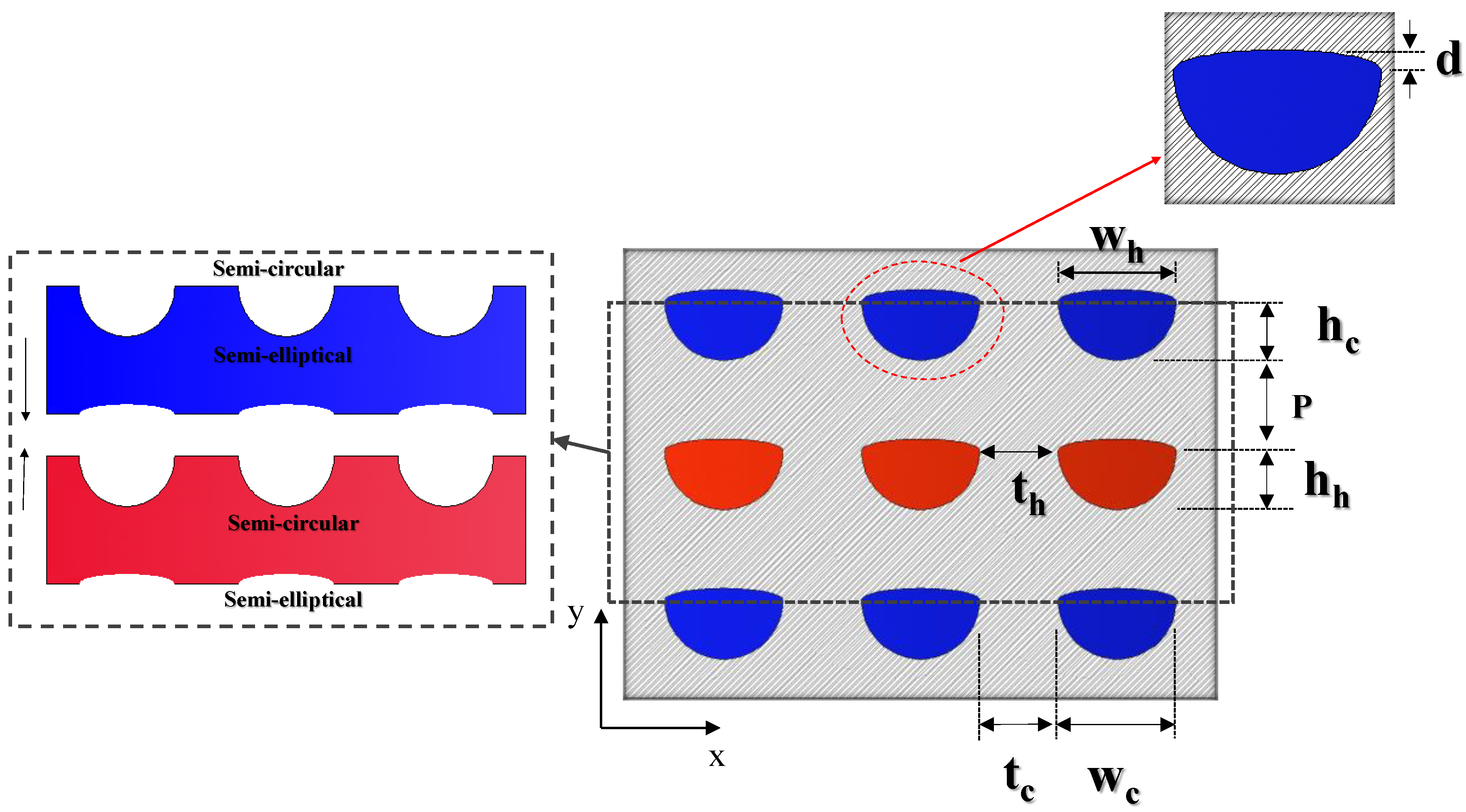
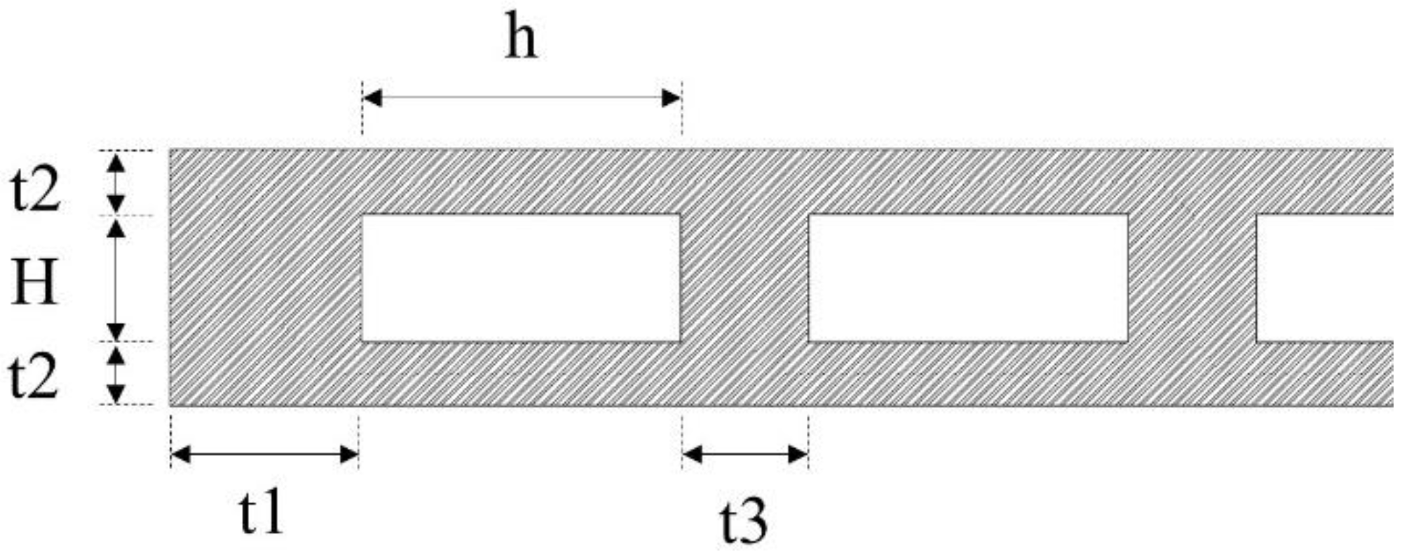
2. Design and Approach

PCHE design is mostly influenced by the common semi-circular channel cross-section. For instance, PCHEs which have been commercially manufactured by Heatric typically have a semi-circular flow cross-section. A new cross-section design based on combined a semi-circular and elliptical shape is proposed. Even though this model of geometry is not usual and still needs many supporting technology developments, especially for the assembly and etching processes, this study is important and innovative to prepare the more advanced PCHE design and manufacturing processes in the future. This study aims to observe the effect of an additional elliptical shape channel from a mechanical integrity point of view after the analysis of thermal–hydraulic performance has been conducted for many studies. The common flow cross-section of the PCHE is shown in Figure 1a.
As per the investigation result of Lee and Lee [11], the maximum stresses occurred at the channel tips. These channel tips are formed during the stacking process of the semi-circular side of the plate and the flat side of the plate. To reduce this sharp corner, an additional elliptical upper channel is proposed to reduce the stress intensity of this flow cross-section design. This elliptical is located above the semi-circular channel. This change in design causes one layer of the stacked plate to have two sides: one semi-circular side, and an additional elliptical side. The proposed flow channel design is shown in Figure 1b. In this design, there will be two etched sides for one layer. One side is a semi-circle side and the other side is a semi-ellipse. The geometric parameters used in this study are shown in Figure 2 and Table 2.

3. Result and Discussion

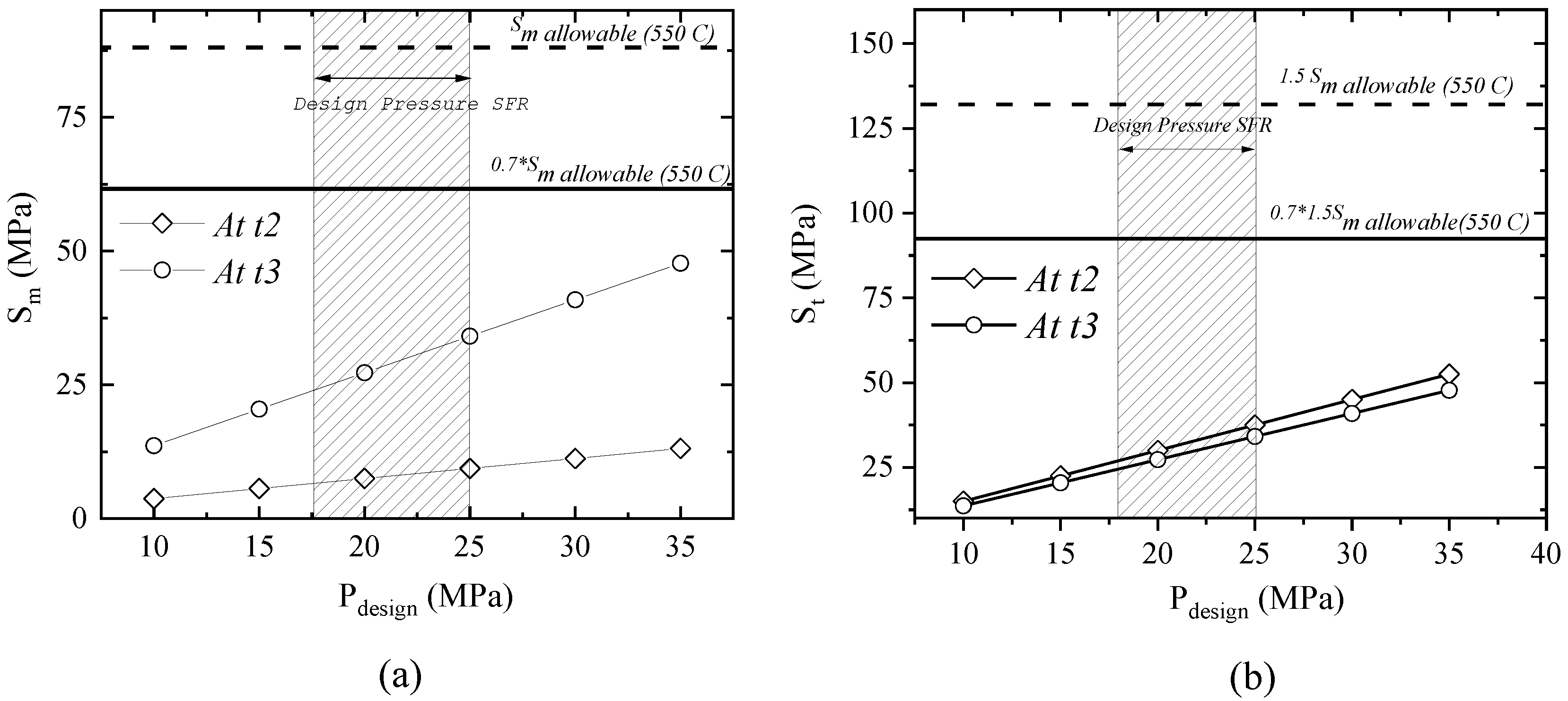
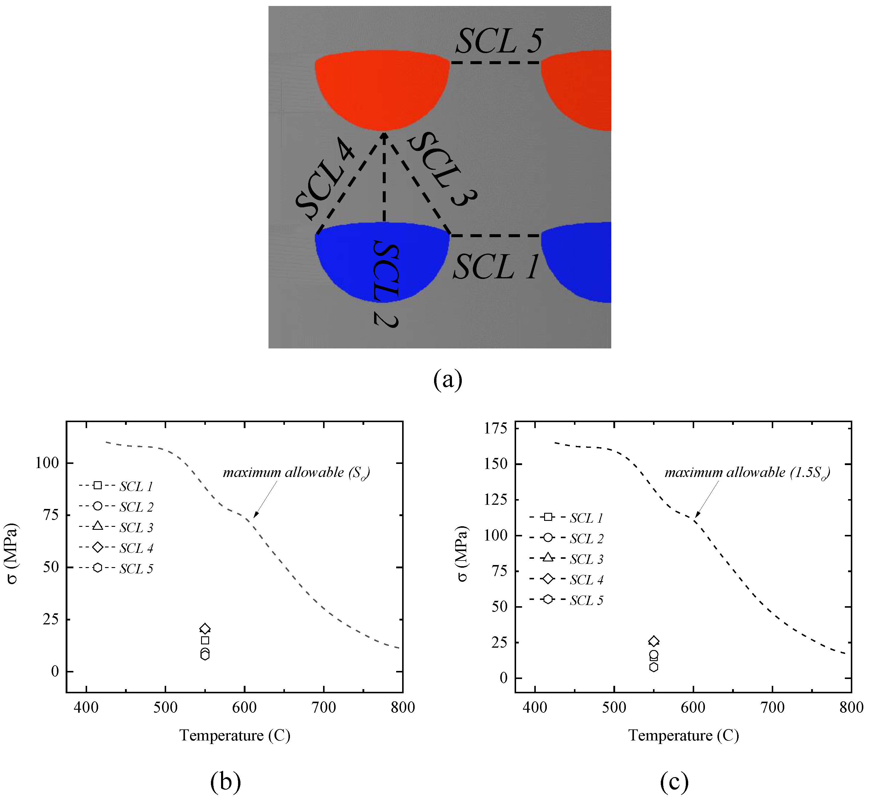
3.1. Simplified Design Assessment by Rule Assessment

Simplified design assessment is an analytical approach that can be used in PCHE mechanical design. This approach is based on a conservative model where the channels are modeled as a stayed plate on a flat plate. This design method has been used by Heatric in mechanical design and applied by Nestell and Sham [22]. In this method, PCHE channel design is simplified by using a model proposed by ASME Section VIII [23] codes for non-circular design vessels. As shown in Figure 3, there are six variables considered in this simplified design. Stayed thickness (t3) and thin wall thickness (t2) are critical in the stress analysis of the rectangular pressure vessel. By considering those design parameters, the membrane stress at a specific area can be estimated. The membrane stress at the stayed plate t3 can be found by using Equation (1):
S m =   P h 2 t 3
where P is the design pressure of PCHE, h is the channel width, and t3 is the ligament between the channel. Membrane stress at the thin wall thickness (t2) is calculated by using Equation (2) below:
S m =   P H 2 t 2
where H is the channel height and t2 is the thin wall thickness. Design by rule also considers the bending stress at the thin wall thickness but stayed plate. Bending stress is not considered the stayed plate because all channels in the same plane are considered at the same pressure. The bending stress can be calculated by using the below Equation (3):
S b =   P h 3 c 12 I 2
I 2 =   t 2 3 12
c =   t 2 2
where I is a moment of inertia and c is the distance from the neutral axis to the extreme fiber. Finally, the stress value can be used in the design criteria which is:
  • The membrane stress at the stayed plate shall not exceed the maximum allowable design stress:
    S m ( t 2 )   S F
  • The membrane stress at the thin wall thickness shall not exceed the maximum allowable design stress:
    S m ( t 3 )   S F
  • The total membrane and bending stress shall not exceed 1.5 times the design stress, where F is a joint factor which is recommended to be 0.7 for diffusion bonding block [24]:
    S T   1.5   S F
Maximum allowable design stress is given by ASME Section III and is a function of the working temperature. Since PCHEs are constructed through the diffusion bonding process, the common understanding is that the bonded structure’s strength is below the material’s value even though the purpose of welding is to achieve the same structural strength as the material. In diffusion bonding technology, there are two materials commonly used for construction: stainless steel 314, 316/316 L and alloy 617. However, in ASME Section III Division 5 at mandatory appendix HBB I−14, the maximum allowable stress intensity for design loading calculation is provided. There are five types of material for elevated temperature nuclear component construction listed as shown in Table 3. For the application of a sodium fast-cooled reactor with the working temperature around 550 °C, five listed materials are usable. However, pressure working conditions should be considered further to decide whether this is acceptable or not. In this study, SS316 was used as a material. The maximum allowable stress intensity for the working environment no more than 550 °C is 88 MPa for SS316.
By considering the geometrical parameter in Table 2, a simplified calculation by considering Equations (1)–(5) was conducted. The calculation result and comparison to the maximum allowable stress intensity is shown in Figure 4. The calculation result shows that the geometrical design can satisfy the design limit of the diffusion bonded printed circuit heat exchanger since the result of both the primary membrane and the total combined primary membrane and bending stress is below the maximum allowable stress intensity for the design pressure up to 35 MPa. The proposed geometry is aimed to be operated under a working pressure and temperature of 16.7 MPa to 22 MPa and 240 °C to 550 °C, respectively.

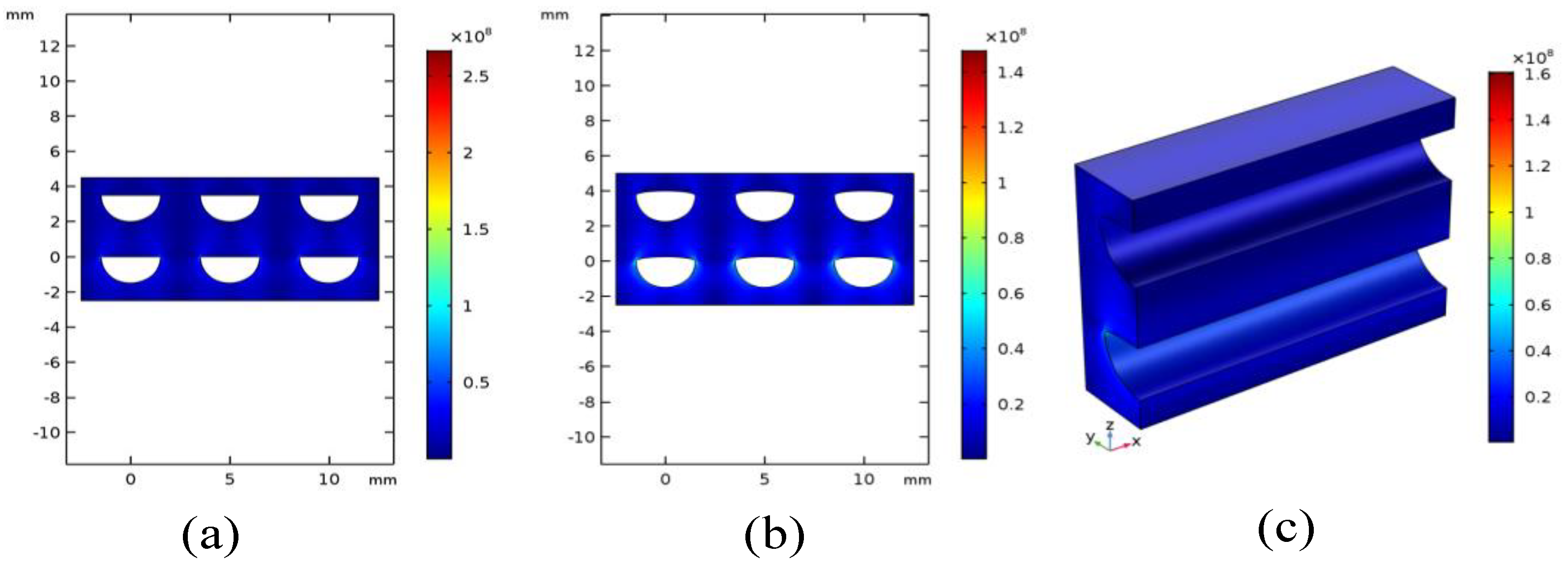
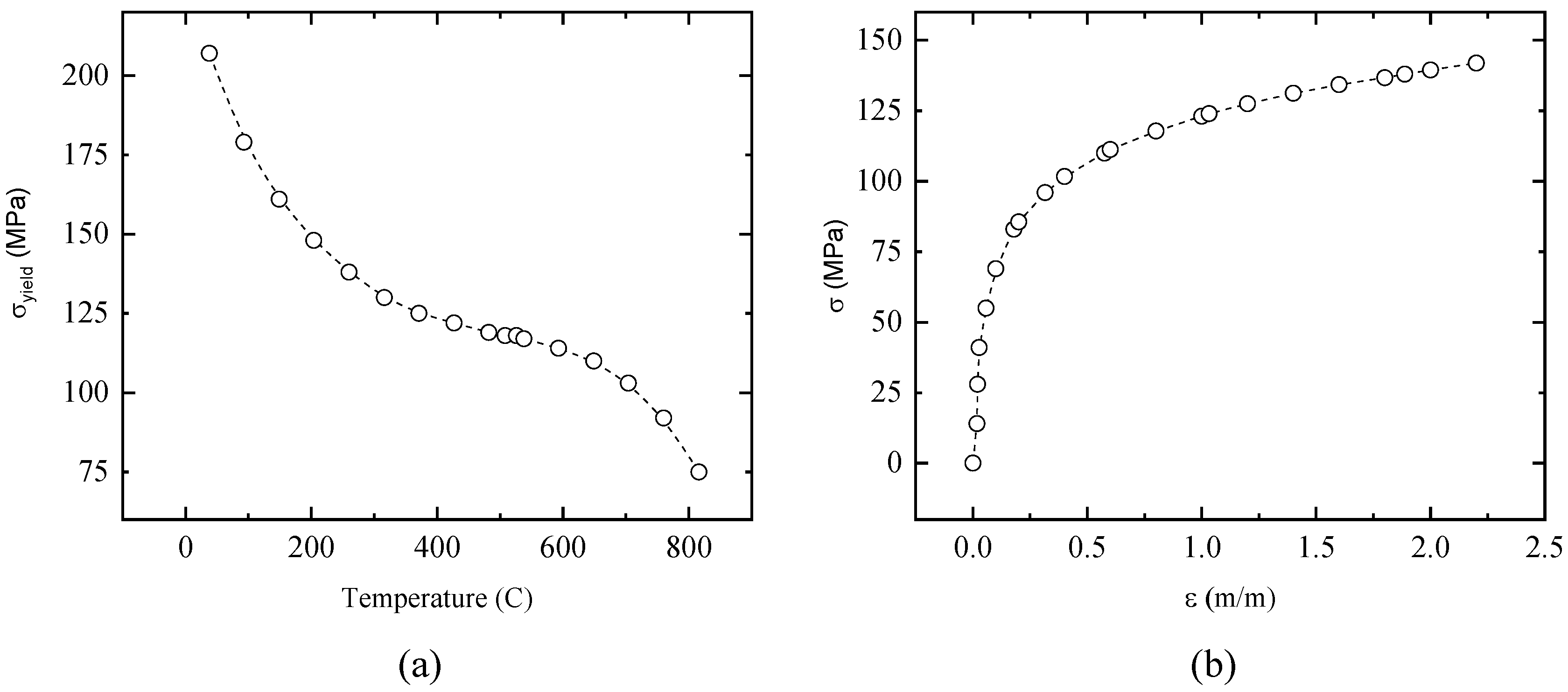
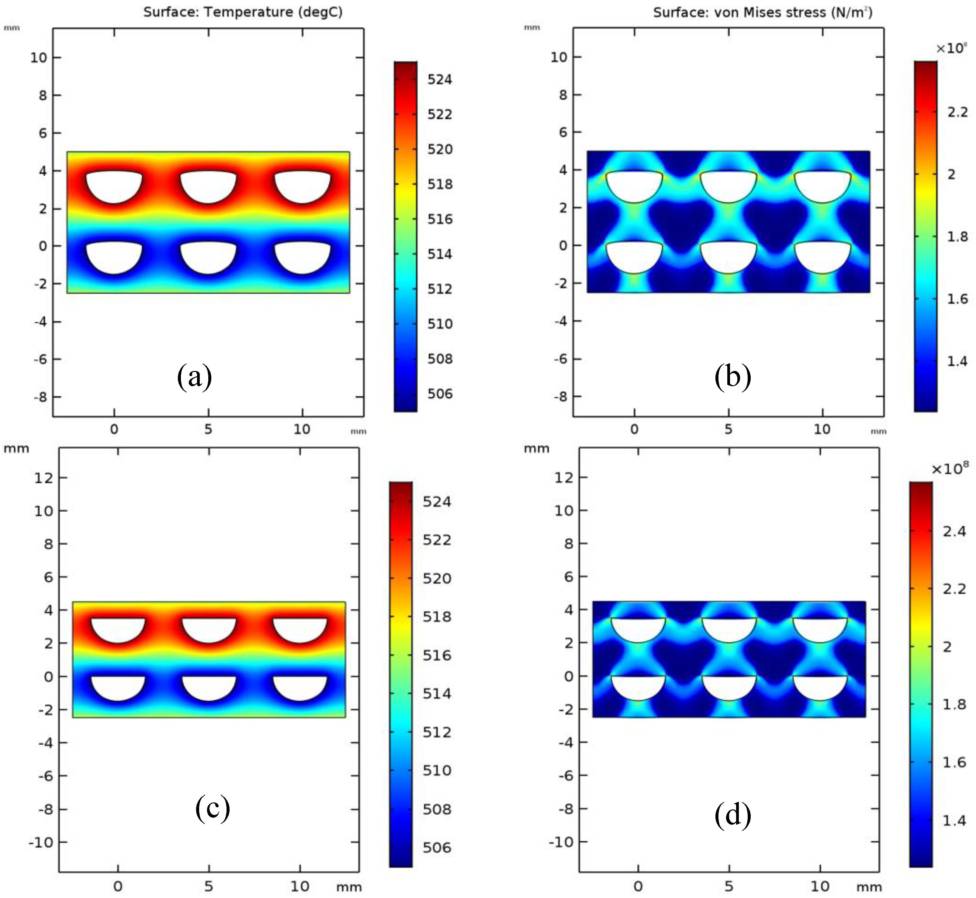
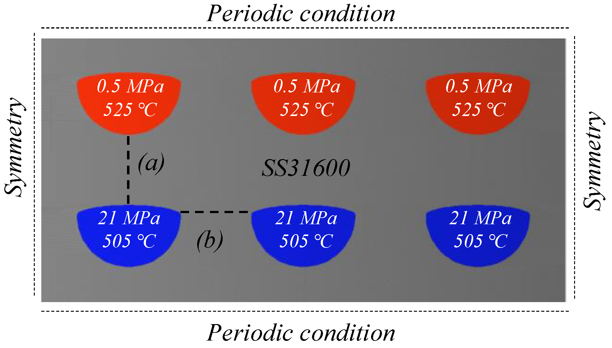
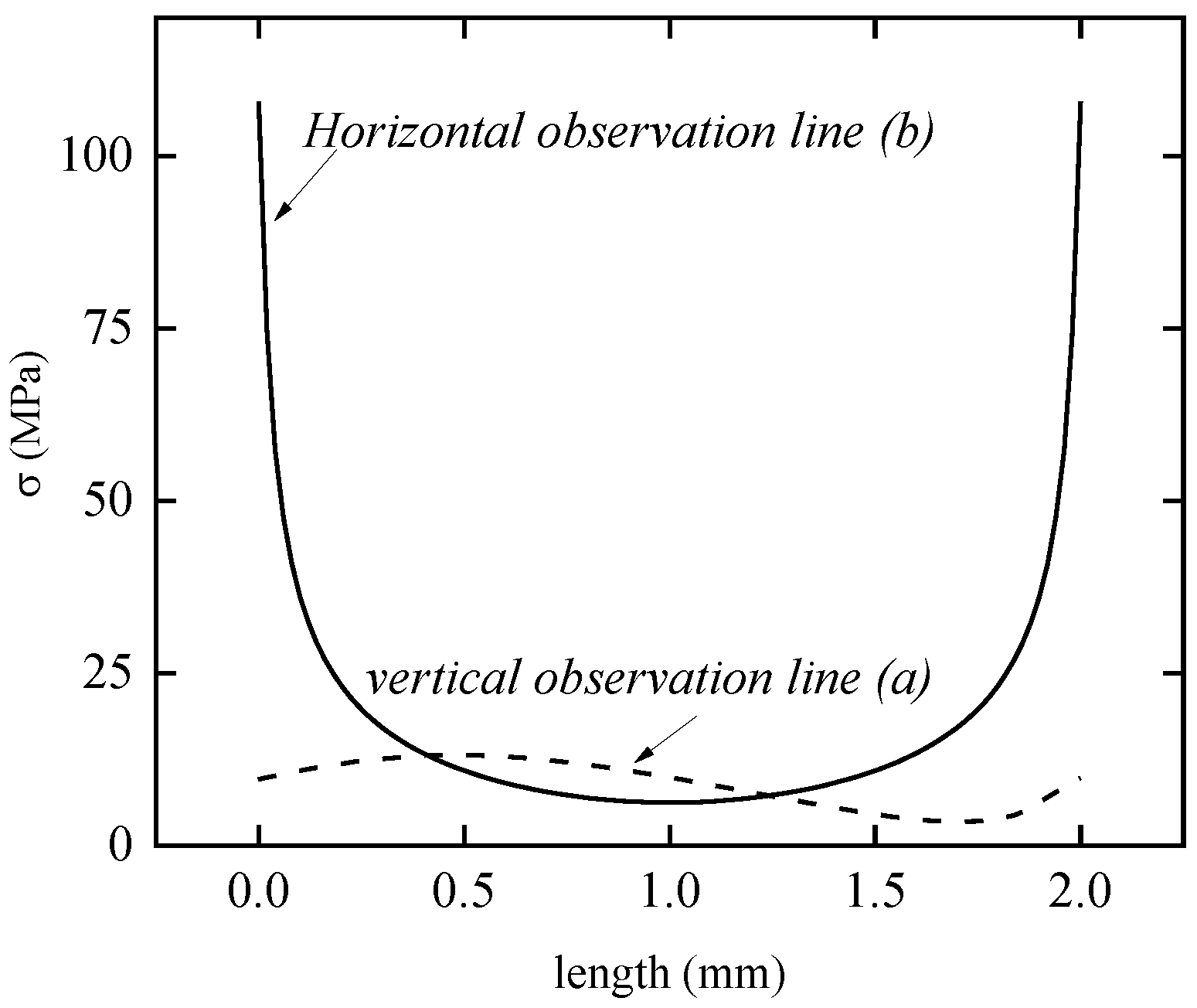
3.2. Mechanical Integrity Assessment by Finite Element Method Simulation

A two-dimensional finite element method simulation by using commercial COMSOL Multiphysics® multiphysics was conducted to see the mechanical integrity of the proposed PCHE design. Comsol multiphysics® is a simulation software for modeling designs, devices, and processes in all fields of engineering, manufacturing, and scientific research [25]. The software was run on ASUS Intel® Xeon® CPU 2.0 GHz (32 CPUs) 64 GB RAM. The pressure boundary condition was used in the simulation by considering the SFR steam generator’s working pressure. The cold side will be subjected to 21 MPa pressure while the hot channel will be subjected to 0.5 MPa pressure. This high difference in pressure conditions can create problems in terms of the mechanical integrity of the system. Lee and Lee’s study has a different boundary condition. Lee and Lee [11] considered unconstrained boundary conditions for the top, bottom, left, and sides of the simulated geometry. However, in this study, the top and the bottom sides were considered as periodic boundary conditions while the left and the right side were symmetric boundary conditions on SUS316 material. The boundary condition used in the simulation is shown in Figure 5.
A mesh independent test was conducted to validate the geometry and mesh construction. The number of elements was varied, and the maximum stress intensity was observed. The error was determined by subtracting the stress intensity from the highest stress intensity. The mesh sensitivity showed that the results converged for different numbers of elements. The triangular element type was used in this numerical simulation study. The mesh sensitivity result is shown in Table 4 for the different additional elliptical channel radius conditions and in Table 5 for the different channel offset arrangement conditions. Figure 6 shows the offset channel arrangement (δ).
Stainless steel 316 is used as the material of PCHE. Material properties used in this study is shown in Figure 7. Two-dimensional and three-dimensional stress distribution under pressure load is shown in Figure 8. It is shown that the maximum stress intensity is 160 MPa and located at the tip channel of the 21 MPa channel. This is an obvious phenomenon since the upper channel has a higher pressure compared to the bottom one. Stress intensity along with line (a) and (b) mentioned in Figure 5 is shown in Figure 9. Line (a) represents the vertical ligament between the upper and lower channels while line (b) represents the horizontal ligament between channels.
The proposed system is modeled under sodium fast-cooled reactor heat exchanger pressure and temperature condition. Hence, the thermal stresses of the individual channel are also important to analyze. To accomplish this, the constant temperature boundary condition of 525 °C and 505 °C were applied for the hot and cold channel, respectively. These boundary conditions were considered as the highest temperature condition in the sodium fast-cooled reactor heat exchanger operation. The periodic boundary condition was also considered and applied at the top and bottom side of the modeled simulation. Symmetric boundary conditions were at the left side and right side. A multilinear isotropic hardening model was used to see the thermal stress of the proposed model. The average isochronous stress–strain curve of SS31600 at various temperatures was obtained from the ASME boiler and pressure vessel code (BPVC) Section III Figure NH-T-1800-B-10. Figure 10a shows the yield stress intensity of SS31600 as a function of temperature. Figure 10b shows the average isochronous stress–strain curve of SS31600 at 631 °C.
The simulation result under the high temperature and pressure which is shown in Figure 11 indicates that the highest stress intensity around 238.5 MPa occurs at the tip area of the hot channel due to the high temperature there. A comparison between the geometry without the additional elliptical upper channel and with a 0.25 mm elliptical upper channel shows that 0.25 mm elliptical upper channel stress intensity is 9% lower It again shows that the additional elliptical channel can lower the stress intensity. This is due to the reduced tip channel angle with the addition of a 0.25 mm elliptical upper channel.
ASME BPVC suggests the different classifications of stress for the judgment of compliance with the construction specification code. Pm and Pb are used based on Equations (6)–(9) as per ASME Section III. In this study, Pm and Pb are obtained by using the stress linearization function provided by COMSOL. Stress linearization method is a method to obtain the primary membrane and primary bending stress for the judgment purpose according to ASME Section VIII Division II. Pm and Pb were obtained by using the linear elastic model simulated under mechanical forces and internal pressure only. Five stress classification lines (SCLs) were defined on the surface to obtain the stress linearization result. These five SCLs represent the two most important observation areas, between two hot channels, between two cold channels, and between the hot and cold channel. Five SCLs were shown in Figure 12a. SCL 1 represents the area between the cold channels where the high pressure occurs. SCL 2, SCL 3, and SCL 4 represent the area between the cold and hot channel. This ligament is important to be observed due to the high-pressure difference between the hot and cold channel. SCL 5 represents the area between two hot channels.
The stress linearization result is shown in Figure 12. It shows that the proposed geometry can satisfy the design loading limit evaluation of ASME Section III. The primary membrane stress levels of all SCLs are lower than the maximum allowable stress intensity (So and 1.5 So) at SCL 1 and 5, and the primary membrane stress and combined primary membrane stress are the same due to the identical pressure condition between the subjected channels. It causes no bending stress to occur in that area. If the linearization result and simplified calculation based on the ASME code result (in Figure 4) are compared, then an almost identical stress intensity can be seen between them. This shows that the simplified calculation and linearization method can be used in mechanical integrity calculation.

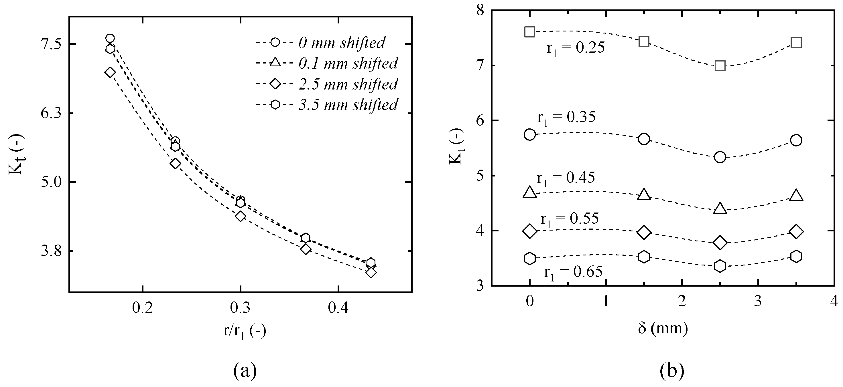
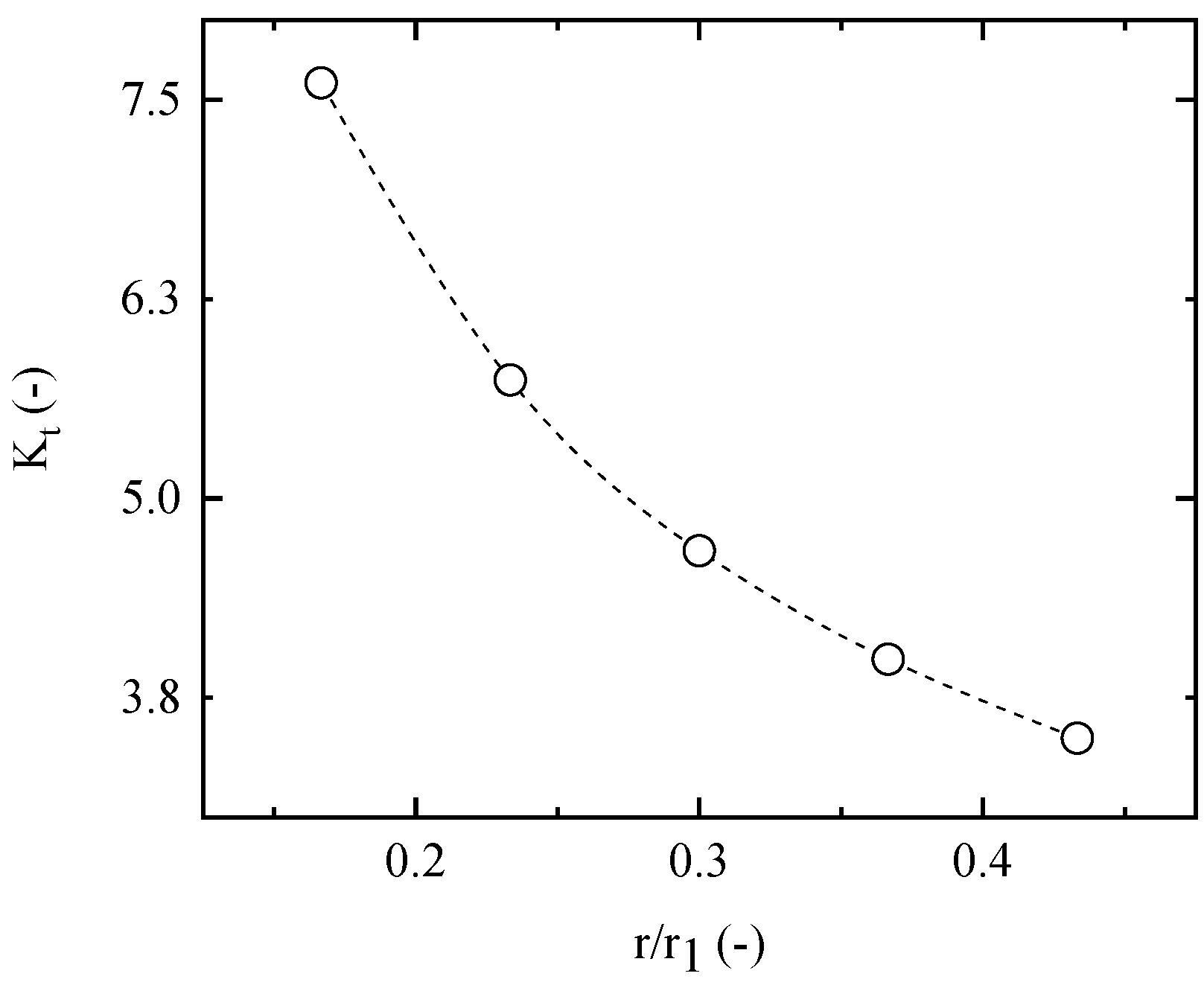
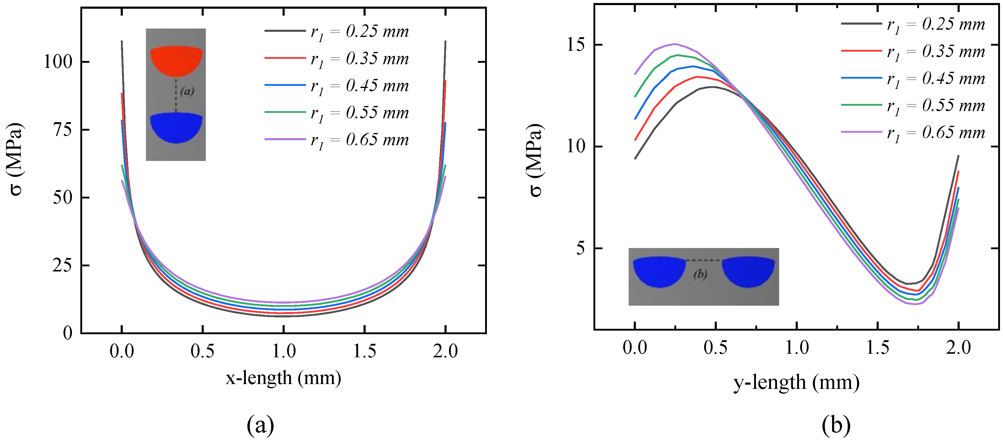
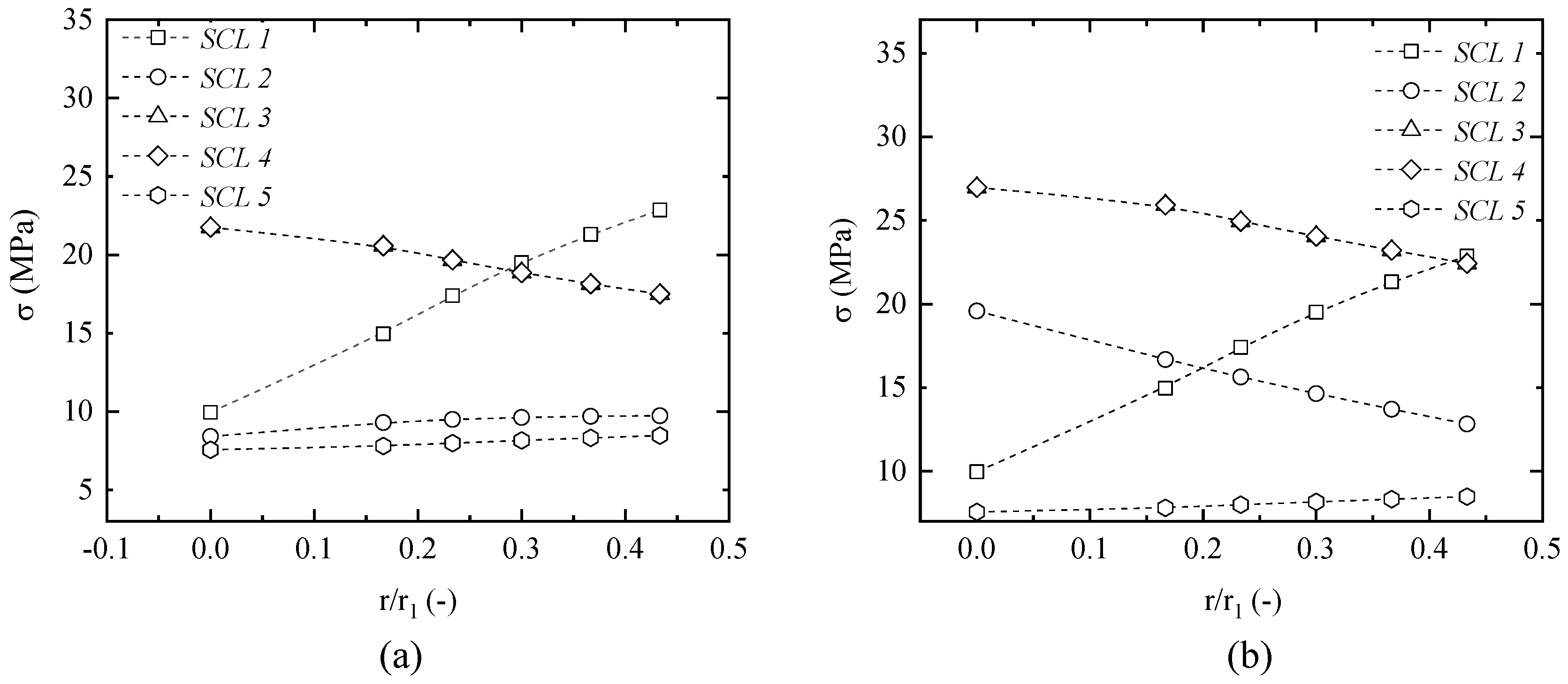
3.3. Effect of Additional Elliptical Channel Radius

An additional elliptical channel radius is an important geometry condition in double-faced PCHE design. This parameter determines the fluid path surface area. To observe the effect of the elliptical channel radius, five different cases were conducted for 0 < r1/r < 0.5 where r1 is the additional elliptical short radius and r is the semi-circular channel radius. One important parameter to be observed is the stress concentration factor. Since the geometry is classified as mini dimension plates with a hole, an accurate calculation of stress distribution and stress concentration factor (SCF) is critical. Besides that, a deeper variety of geometric discontinuities or effects with different sizes and shapes is also important to get the best design based on the standard limit given. The stress concentration factor was defined as the ratio of maximum stress intensity to the value of nominal stress. Figure 13 shows the effect of an additional elliptical channel radius to the stress concentration factor of the system. The figure clearly shows that the addition of the elliptical channel radius can reduce the stress concentration factor by double-etched PCHE. Increasing an additional elliptical shape radius up to 0.65 mm can reduce the stress concentration factor by more than 100%. The condition near the edge of the channel has been changed due to the addition of the elliptical upper channel.
Stress intensity also slightly changes with the increase in additional elliptical channel radius. Figure 14 shows the stress intensity between two cold channels (a) and between the hot and cold channels (b). It shows that stress intensity along the line between two cold channels slightly decreases with the increase in elliptical shape factor.
Stress linearization result of the membrane stress intensity as shown in Figure 15 shows that the increase in elliptical channel radius can increase the membrane stress at SCL 1 which is a ligament between two cold channels with a pressure of 21 MPa. However, this reduces the membrane stress at SCLs 3 and 4 which is a ligament between the hot and cold channels with a pressure difference of 20.5 MPa. Another SCL shows a slightly similar stress intensity. The combined primary + bending stress intensity of the linearization method shows that the stress intensity of SCL 1 increases by around 33% with the increase in the elliptical upper channel radius. However, it is interesting that there was a decrease in the stress intensity of SCL 2, SCL 3, and SCL 4 with the increase in elliptical upper channel radius around 5%. This means that the increase in elliptical channel radius can reduce the bending stress that occurs on the surface.

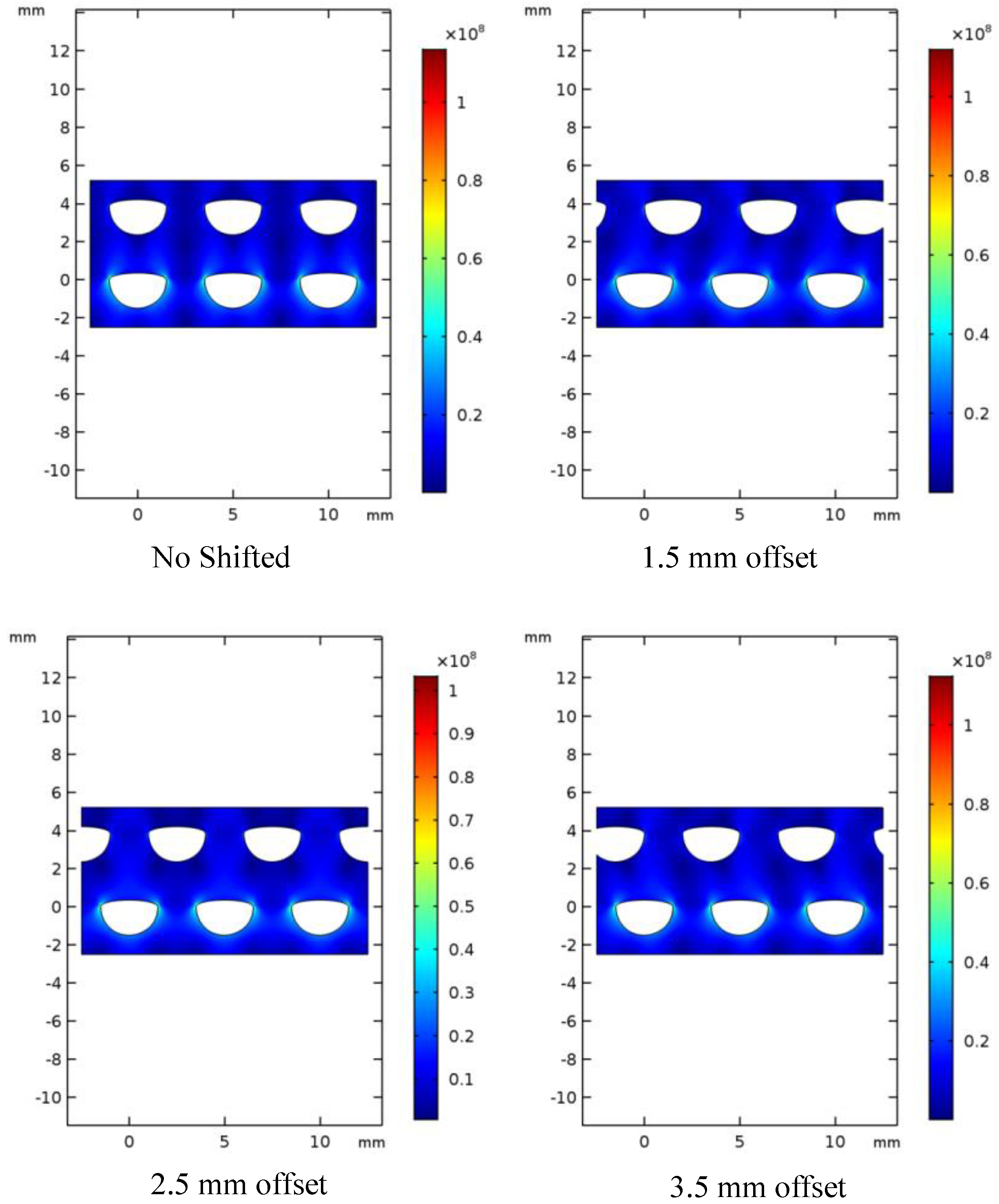
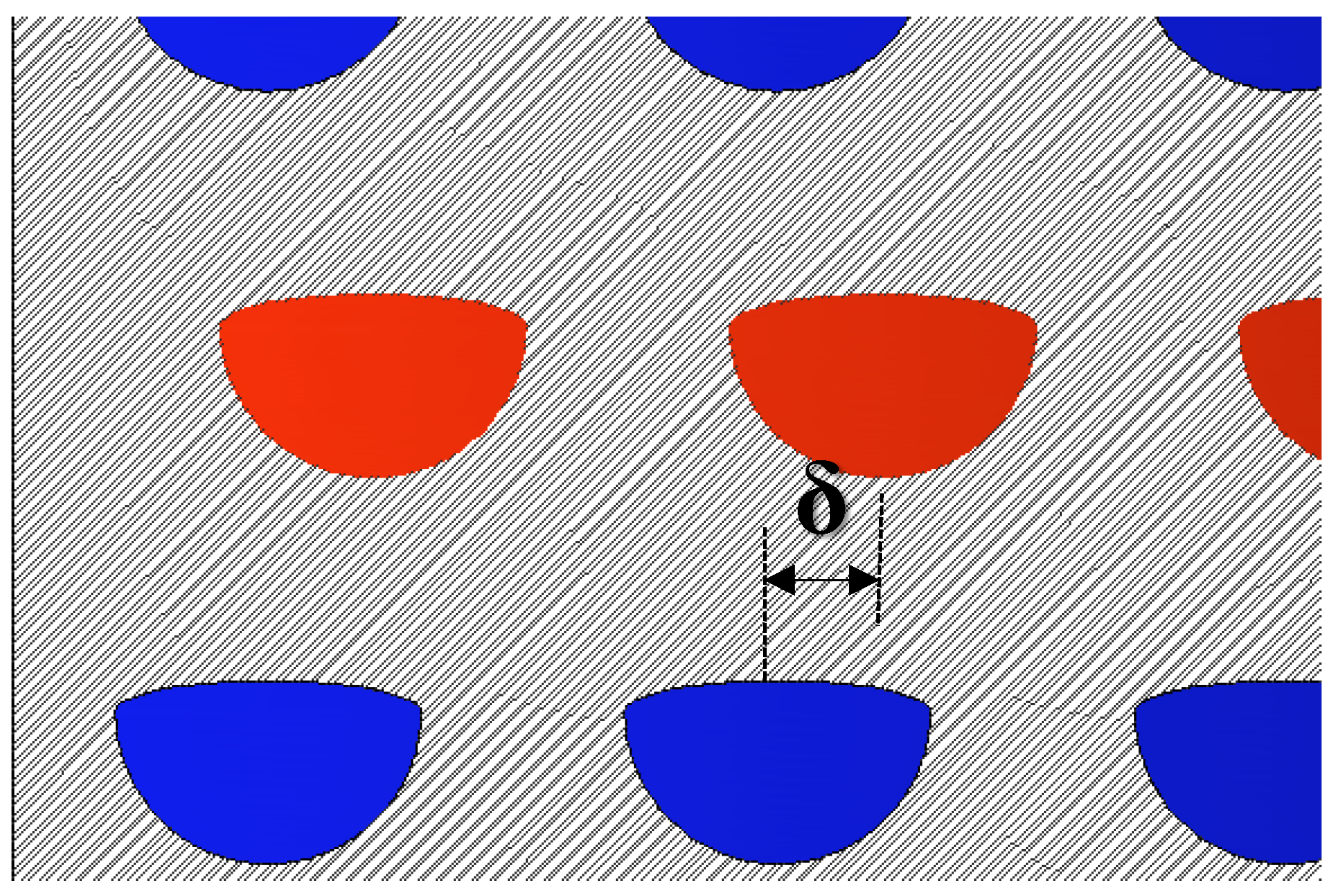
3.4. Effect of Shifted Channel Arrangement

A PCHE is a device that consists of a series of plates with numbers of cut-out channels. They are stacked on top of each other to assemble one PCHE unit. Shifted channel arrangement, also known as an offset model, is a model where the plates are arranged in offset horizontally. In the PCHE construction side, this model can be obtained by shifting plates before the diffusion bonding process.
The simulation by using COMSOL Multiphysics was conducted for the stress analysis of this shifted channel configuration. Then, 21 MPa and 0.5 MPa were applied for the cold and hot channel boundary conditions, respectively. Figure 16 shows the von Mises stress distribution for 0.25 elliptical radius channels under non-offset configuration and offset configurations. The maximum stress still occurs on the corner of the channel because of the corner strain of pressure boundary conditions. The maximum von Mises stress is 152.7 MPa and 139.8 MPa of non-offset and 2.5 mm offset configuration, respectively. This means that the maximum stress intensity of 1.5 mm offset configuration is 2% lower compared to the non-offset configuration. A 2.5 mm offset configuration lowers 6% of THE maximum stress intensity while 3% of the maximum stress intensity is lowered under a 3.5 mm offset configuration. The simulation result also shows that the stress concentration factor (Kt) decreases with the offset condition. Figure 17 shows that the stress concentration factor of 2.5 mm offset configuration is the lowest compared to 0.1 and 3.5 mm offset configuration. Simulated cases show that 2.5 mm can be an optimum offset length for a double-etched printed circuit heat exchanger.

4. Conclusions

Finite element analysis simulation has been conducted to observe the mechanical integrity of double-etched printed circuit heat exchanger design. Even this design still needs more efforts to be applied in the future, but the design of double-etched design shows a promising and safer design in terms of a mechanical integrity point of view after some previous study mentioned double-faced PCHE from a thermal–hydraulic point of view. In this case, a sodium fast-cooled reactor steam generator heat exchanger is taken as the model for the proposed PCHE design. By considering the ASME Section III construction rule, the proposed design can comply with the design criteria where the primary membrane stress (Pm) and combined with primary bending stress (Pm + Pb) are still below maximum requirement criteria. The application of an additional ellipse upper channel helps the stress intensity decrease in the proposed PCHE channel. Five different cases were conducted for 0 < r1/r < 0.5 where r1 is the additional elliptical short radius and r is the semi-circular channel radius. The simulation shows that the stress intensity was reduced by up to 24%. Apart from that, the stress concentration factor also reduces with the increase in additional elliptical channel radius.
Besides that, the offset channel arrangement is also one of the possible arrangements that can be used in this type of PCHE. This offset arrangement can be done by shifting one plate to another during the construction process. This offset arrangement comes with the promising stress intensity decrease. Simulation results show that the 2.5 mm offset configuration can decrease 9% of the maximum stress intensity compared to the non-offset configuration. This work proposed an additional elliptical upper channel with a 2.5 mm offset configuration is an optimum design that can be applied in PCHE design.

Author Contributions

Conceptualization, A.P.S., and J.-Y.L.; methodology, A.P.S.; software, A.P.S.; validation, A.P.S., and J.-Y.L.; formal analysis, data curation, A.P.S.; writing—original draft preparation, A.P.S.; writing—review and editing, A.P.S. and J.-Y.L.; visualization, A.P.S.; supervision, J.-Y.L. All authors have read and agreed to the published version of the manuscript.

Funding

This work was supported by the National Research Foundation of Korea (NRF) grant, funded by the Korea government (MSIP) (No. 2017M2A8A4018624).

Conflicts of Interest

The authors declare no conflict of interest.

Abbreviations

ASMEAmerican Society of Mechanical Engineers
PCHEPrinted Circuit Heat Exchanger
FEMFinite Element Method
SCO2Supercritical Carbon dioxide
SFRSodium Fast-Cooled reactor
TESThermal Energy Storage
IHXIntermediate Heat Exchanger
HTGRHigh-Temperature Gas Reactor
SCLStress Classification Line
Symbol
SmMembrane stress model of simplified design by ASME Code
SbBending stress model of simplified design by ASME code
FJoint factor (0.7 for diffusion bonding block)
SoMaximum allowable stress intensity
PmPrimary membrane stress intensity (MPa)
PbPrimary bending stress (MPa)
SbPrimary bending stress
rSemi-circular channel radius
r1Additional elliptical upper channel radius
KtStress concentration factor
δ Offset length (center hot channel to center cold channel)
kThermal conductivity
αCoefficient thermal expansion
EYoung’s modulus
ρDensity
νPoisson’s ratio
CpSpecific heat at constant pressure

References

  1. Ҫengel, Y.A. Heat Exchanger. In Heat Transfer a Practical Approach, 2nd ed.; McGraw Hill: New York, NY, USA, 2004; pp. 667–704. [Google Scholar]
  2. Thulukkanam, K. Heat Exchangers Introduction, Classification, and Selection. In Heat Exchanger Design Handbook, 2nd ed.; CRC Press: New York, NY, USA, 2013; pp. 1–34. [Google Scholar]
  3. Asadi, M.; Xie, G.; Sunden, B. A review of heat transfer and pressure drop characteristics of single and two phases microchannel. Int. J. Heat Mass Transf. 2014, 79, 34–53. [Google Scholar] [CrossRef]
  4. Chen, M.; Sun, X.; Christensen, R.N.; Shi, S.; Skavdahl, I.; Utgikar, V.; Sabharwall, P. Experimental and numerical study of a printed circuit heat exchanger. Ann. Nucl. Energy 2016, 97, 221–231. [Google Scholar] [CrossRef] [Green Version]
  5. Chen, M.; Sun, X.; Christensen, R.N.; Shi, S.; Skavdahl, I.; Utgikar, V.; Sabharwall, P. Pressure drop and heat transfer characteristic of a high-temperature printed circuit heat exchanger. Appl. Therm. Eng. 2016, 108, 1409–1417. [Google Scholar] [CrossRef] [Green Version]
  6. Li, X.; Le Pierres, R.; Dewson, S.J. Heat Exchanger for the Next Generation of Nuclear Reactors. In Proceedings of the International Congress on Advances in Nuclear Power Plants, Reno, NV, USA, 4–8 June 2006; pp. 201–209. [Google Scholar]
  7. Patil, R.; Anand, S. Thermo-structural fatigue analysis of shell and tube type heat exchanger. Int. J. Press. Vessel. Pip. 2017, 155, 35–42. [Google Scholar] [CrossRef]
  8. Mylavarapu, S.K.; Sun, X.; Glosup, R.E.; Christensen, R.N.; Patterson, M.W. Thermal Hydraulic Performance testing of Printed Circuit heat exchangers in a high-temperature helium test facility. Appl. Therm. Eng. 2014, 65, 605–614. [Google Scholar] [CrossRef]
  9. Kim, J.H.; Baek, S.; Jeong, S.; Jung, J. Hydraulic Performance of a microchannel PCHE. Appl. Therm. Eng. 2010, 30, 2157–2162. [Google Scholar] [CrossRef]
  10. Sung, J.; Lee, J.Y. Effect of tangled channels on the heat transfer in a printed circuit heat exchanger. Int. J. Heat Mass Transf. 2017, 115, 647–656. [Google Scholar] [CrossRef]
  11. Lee, Y.; Lee, J.I. Structural assessment of intermediate printed circuit heat exchanger for sodium-cooled fast reactor with supercritical CO2 cycle. Ann. Nucl. Energy 2014, 73, 84–95. [Google Scholar] [CrossRef]
  12. Song, K.N.; Hong, S.D. Structural Integrity Evaluation of a Lab-Scale PCHE Proto-type under the Test Conditions of HELP. Sci. Technol. Nucl. Install. 2013, 1–7. [Google Scholar] [CrossRef] [Green Version]
  13. Simanjuntak, A.P.; Lee, J.Y. Mechanical Integrity Analysis of a Printed Circuit Heat Exchanger with Channel Misalignment. Appl. Sci. 2020, 10, 2169. [Google Scholar] [CrossRef] [Green Version]
  14. Winter, N.; Becton, M.; Zhang, L.; Wang, X. Effects of pore design on mechanical properties of nanoporous silicon. Acta Mater. 2017, 124, 127–136. [Google Scholar] [CrossRef] [Green Version]
  15. Vo, T.; He, B.; Blum, M.; Damone, A.; Newell, P. Molecular scale insight of pore morphology relation with mechanical properties of amorphous silica using ReaxFF. Comput. Mat. Sci. 2020, 183, 109881. [Google Scholar] [CrossRef]
  16. Lee, S.M.; Kim, K.Y.; Kim, S.W. Multi-objective optimization of a double-faced type printed circuit heat exchanger. Appl. Therm. Eng. 2013, 60, 44–50. [Google Scholar] [CrossRef]
  17. Ma, T.; Pasquier, U.; Chen, Y.; Wang, Q. Numerical study on thermal-hydraulic performance of a two-sided etched zigzag-type high-temperature printed circuit heat exchanger. Energy Procedia 2017, 142, 3950–3955. [Google Scholar] [CrossRef]
  18. Lee, S.M.; Kim, K.Y. Comparative study on performance of a zigzag printed circuit heat exchanger with various channel shapes and configuration. Heat Mass Transf. 2013, 49, 1021–1028. [Google Scholar] [CrossRef]
  19. Lee, S.M.; Kim, K.Y. Thermal Performance of a Double-Faced Printed Circuit Heat Exchanger with Thin Plates. J. Thermophys. Heat Transf. 2014, 28, 251–257. [Google Scholar] [CrossRef]
  20. Yoo, J.; Chang, J.; Lim, J.Y.; Cheon, J.S.; Lee, T.H.; Kim, S.K.; Lee, K.L.; Joo, H.K. Overall System Description and Safety Characteristics of Prototype Gen IV Sodium Cooled Fast Reactor in Korea. Nucl. Eng. Technol. 2016, 48, 1059–1070. [Google Scholar] [CrossRef] [Green Version]
  21. ASME. An. International Code 2015 ASME Boiler & Pressure Vessel Code Section III. Rules for Construction of Nuclear Facility Components Division 5 High. Temperature Reactors; American Society of Mechanical Engineer: New York, NY, USA, 2015. [Google Scholar]
  22. Nestell, J.; (MPR Associates, Inc., Washington DC, USA); Sham, T.L.; (Oak Ridge National Laboratory, Tennessee, USA). ASME Code Considerations for the Compact Heat Exchanger. Personal communication, 2015. [Google Scholar]
  23. ASME. An. International Code 2015 ASME Boiler & Pressure Vessel Code Section VIII. Rules for Construction of Pressure Vessel Division 2; American Society of Mechanical Engineer: New York, NY, USA, 2015. [Google Scholar]
  24. Pierres, R.L.; Southal, D.; Osborne, S. Impact of Mechanical Design Issues on Printed Circuit Heat Exchangers. In Proceedings of the SCO2 Power Cycle Symposium, Boulder, CO, USA, 24–25 May 2011. [Google Scholar]
  25. Comsol Multiphysics Official Website. Available online: www.comsol.com (accessed on 17 July 2020).
Figure 1. Cross-section of the printed circuit heat exchanger (PCHE) circuit (a) common cross flow section (b) improved with the additional elliptical upper channel.
Energies 13 04711 g001
Figure 2. Proposed design cross-section geometry parameters.
Energies 13 04711 g002
Figure 3. The simplified design used to assess the proposed design.
Energies 13 04711 g003
Figure 4. (a) Primary membrane stress (b) and the combined primary bending stress intensity under the different design pressure conditions.
Energies 13 04711 g004
Figure 5. Applied boundary condition for a simulation study.
Energies 13 04711 g005
Figure 6. Simulated offset arrangement (δ).
Energies 13 04711 g006
Figure 7. Material properties used in the simulation. (a) Young’s modulus; (b) Poisson’s ratio; (c) Density; (d) Thermal expansion coefficient; (e) Thermal conductivity; (f) Specific heat capacity.
Energies 13 04711 g007
Figure 8. The von Mises stress distribution (a) without additional channel radius (b) under a 0.25 mm additional channel radius; (c) along the channel under a 0.25 mm additional channel radius.
Energies 13 04711 g008
Figure 9. Stress intensity along the observation line.
Energies 13 04711 g009
Figure 10. (a) Yield stress function of the temperature and (b) the isochronous stress–strain curve.
Energies 13 04711 g010
Figure 11. Pressure + thermal stress simulation result (b,d): temperature distribution (a,c).
Energies 13 04711 g011
Figure 12. (a) Five stress classification lines (SCLs); (b) linearization result of membrane stress and compared to So; and (c) the linearization result of membrane + bending stress and compared to 1.5 So.
Energies 13 04711 g012
Figure 13. Stress concentration factor (Kt) decreases with the increase in elliptical channel radius.
Energies 13 04711 g013
Figure 14. (a) Stress intensity along the horizontal line cold-to-cold channel; and (b) stress intensity along the vertical line hot-to-cold channel.
Energies 13 04711 g014
Figure 15. Stress linearization result at all SCLs at the different elliptical shape radii: (a) primary membrane stress; and (b) primary + bending stress.
Energies 13 04711 g015
Figure 16. The von Mises stress of the four different channels offset configurations.
Energies 13 04711 g016
Figure 17. (a) Effect of elliptical channel radius on the stress concentration factor (b) Effect of offset channel configuration on the stress concentration factor (Kt).
Energies 13 04711 g017
Table 1. Thermodynamic design parameters for heat exchanger.
ConditionCold Channel Hot Channel
Pressure (MPa)Temperature (°C)Pressure (MPa)Temperature (°C)
inlet19.7230.00.5528.0
outlet19.7503.00.5322.0
Table 2. Geometric parameter of this study.
Geometric ParameterDescription
hcH (cold)0.9 mmCold channel height
hhH (hot)0.95 mmHot channel height
whh (hot)1.80 mmHot channel width
wch (cold)1.9 mmCold channel width
pt32 mmHot–cold channel ligament
tct2 (cold)0.60 mmCold–cold channel ligament
tht2 (hot)0.70 mmHot–hot channel ligament
Table 3. Maximum allowable stress intensity for a different type of material.
Temperature (°C)Maximum Allowable Stress Intensity (MPa)
SS 304SS 316Alloys N0881021/4 Cr-1Mo9Cr-1Mo-V
425105110105116172
450102108104116165
47510110810399154
5009910710181133
525861019964117
55074888948102
5756977743581
6006576682662
625516262-46
650425151-29
675343941--
700273034--
725212328--
750171823--
7751413---
8001111---
Table 4. Maximum stress intensity on the different maximum mesh element sizes at the different additional elliptical channel radii (r1).
Number of ElementsMax. Stress Intensity (MPa)
r1 = 0.25 mmr1 = 0.35 mmr1 = 0.45 mmr1 = 0.55 mmr1 = 0.65 mm
32,942152.69115.0894.1679.7269.89
10,379151.18114.9193.5979.7270.96
8815152.43115.9294.8480.9570.81
4492152.97116.1394.5381.5971.56
Table 5. Maximum stress intensity on the different maximum mesh element sizes at the different offset arrangements (δ).
Number of ElementsMax. Stress Intensity (MPa)
δ = 0 mmδ = 1.5 mmδ = 2.5 mmδ = 3.5 mm
32,942152.69148.57139.80148.25
10,379151.18144.99138.37147.57
8815152.43147.48138.30146.94
4492152.97149.66140.43149.11

