Article

Numerical Investigation of a Free-Piston Hydrogen-Gasoline Engine Linear Generator

School of Mechanical Engineering, Beijing Institute of Technology, Beijing 100081, China
*
Author to whom correspondence should be addressed.
Energies 2020, 13(18), 4685; https://doi.org/10.3390/en13184685
Submission received: 27 July 2020 / Revised: 25 August 2020 / Accepted: 7 September 2020 / Published: 9 September 2020

Abstract

:
The free-piston engine linear generator (FPELG) is being investigated by many researchers because of its high thermal efficiency and its variable compression ratio. However, all researchers focused on the FPELG characteristics with mono-fuel. Therefore, in this paper, the performance of the FPELG that has adopted gasoline with hydrogen as fuel is investigated. The method of coupling the zero-dimensional dynamics model with the multi-dimensional CFD (Computational Fluid Dynamics) combustion model was applied during the simulation process. According to the results, the piston TDC (Top Dead Center), the piston peak piston velocity, and the system operation frequency show a negative correlation with the increase of hydrogen fractions. However, the peak in-cylinder pressure was increased with the hydrogen volume fraction increase, due to the fast flame speed and short combustion duration characteristics of hydrogen. Meanwhile, the indicated efficiency of the free-piston engine was increased from 32.3% to 35.3% with the hydrogen volume fraction change from 0% to 4.5%, when the free-piston engine operates at stoichiometric conditions with fixed ignition timing. In addition, with the ignition timing advance increase, the piston TDC was decreased. The peak piston velocity and the peak in-cylinder pressure were in negative correlation with the ignition timing advance. While the engine indicated that the efficiency was increased with the equivalent degree of ignition timing from 20° to 16°. Therefore, the ignition timing of the FPELG under the spark-ignition combustion mode is supposed to be an effective and practical control variable.

1. Introduction

The free-piston internal combustion engine linear generator (FPELG), as a novel fuel-to-electricity energy conversion device, has been studied by many groups in the whole world because of the unique operation characteristics [1,2,3,4,5,6]. The FPELG consists of the free-piston engine and the linear generator directly [3]. Its operation principle is that the high-temperature and high-pressure gas is generated, alternatively during the combustion process in the cylinder of the free-piston engine, then the gas drives the mover (including the piston assembly and the linear generator moving rod) to move, and the linear generator converts parts of the mover kinetic energy into electricity [5]. According to the FPELG operation principle, it is found that the FPDLG shows many differences with the conventional internal combustion engines (ICEs) in terms of the construction, operation performance, combustion characteristics, etc. [6,7]. Compared with the conventional ICEs, the FPELG has many advantages, such as the high indicated thermal efficiency, the short energy conversion-chain, multi-fuel, and multi-combustion modes feasibility [8]. The only moving component of the FPELG is the mover so that the friction loss is reduced significantly [9,10].
The concept of the free-piston engine was first proposed in the 1920s by Pescare, which was applied on the air compressors during that time [11]. Then the researchers also applied it to gas generators and gas turbines, etc. [12]. Unfortunately, these free-piston engines were abandoned until the 1960s because the free-piston engines showed disadvantages compared with the conventional ICEs [6]. Recently, the free-piston engines were investigated by many research institutes in the world, which have been matched to the linear generation or the hydraulic power system [12].
Nigel Clark group developed a two-stroke FPELG under the spark-ignition combustion mode in the 1990s. The bore of the free-piston engine was 36.5 mm and the maximum stroke was 50 mm [13,14,15,16,17]. They built the whole operating process (including the gas exchange process, the compression process, the combustion process, and the expansion process) models. A parametric analysis of the system performance was undertaken, such as the piston displacement, velocity, the in-cylinder gas pressure, and the free-piston engine output power [16]. Meanwhile, the experimental results demonstrated that the output power from the prototype could achieve 316 W at 23.1 Hz. However, the high cycle variations were spread out during the working process. Therefore, the prototype could not operate stably.
Peter Van Blarigan’s group started the FPELG research since the 1990s [18,19,20,21]. The homogeneous charge compression ignition (HCCI) combustion mode was applied to the FPELG during the high compression ratio and the lean mixture gas, high engine thermal efficiency was achieved, and it was the same as the Otto cycle when they investigated the various hydrogen-containing fuels [20]. According to the simulation results, the piston acceleration was larger than that of the conventional ICEs, and the peak value was reached when the piston near the Top Dead Center (TDC). In addition, the compression stroke was slow, and the expansion stroke was fast. The experimental results from the fast expansion device demonstrated that the energy conversion efficiency (fuel-to-electricity conversion efficiency) and the emission of the FPELG were the same as the fuel cell when the hydrogen-containing fuel was applied on the FPELG [21].
Fredriksson and Denbratt studied and optimized the combustion system and the direct fuel injection system of the FPEC (Free piston Energy Converter), based on a European Union energy project [22,23]. They investigated the FPEC performance with the Simulink and GT-power software. Based on the simulation results of the operation characteristics, the researchers optimized the combustion process. In addition, the results demonstrated a changed trend of the emissions (including Soot, NOx, and COx) with the stoichiometry and the in-cylinder gas temperature.
Chia-Jui Chiang and Ocktaeck Lim investigated the performance of the FPELG under various combustion modes, respectively [24,25]. Three combustion modes, such as the Spark ignition (SI) mode, lean combustion mode, and the HCCI combustion mode, were compared when the isooctane was applied on the FPELG as the fuel. The results from the Chia-Jui Chiang group showed that the output power of the FPELG was much higher when the SI combustion mode was applied and the stoichiometry (it was 1). In addition, the indicated thermal efficiency of the free-piston engine was higher when the HCCI mode was applied [24]. According to the results from the Ocktaeck Lim group, it was found that the SI combustion mode transfered to the HCCI combustion mode smoothly, and the system was suggested to operate in a specific condition when propane was used as the fuel [25].
Hidemasa Kosaka et al. started to research the FPELG since 2013, and a two-stroke prototype was developed to evaluate the operation characteristics [26,27]. The researchers discussed the SI model and the Premixed charged compression ignition (PCCI) combustion model was applied to the FPELG. The simulation results revealed that when the PCCI combustion model was used, the free-piston engine thermal efficiency was higher than that in the SI combustion model. The output power of 10 kW was reported to be achieved, and the engine thermal efficiency was about 42% in the PCCI combustion mode. However, the ignition timing was difficult to control when the PCCI combustion model was applied. In addition, the experimental results showed that the prototype of the FPELG could operate for a long time while the un-normal combustion frequently occurred.
Roskilly and Boru Jia et al. investigated the FPELG performance from the simulation results [2,4,28,29,30,31,32]. The dynamic characteristics, the thermodynamic process, and the operation performance of the free-piston engine were analyzed. The simulation results showed that the parameters of the FPELG were highly coupled and in a nonlinear relationship [2,30,32]. They found that the piston trajectory would affect the in-cylinder gas flow, while the influence on the combustion process of the free-piston engine was not obvious. The FPELG was reported to show advantages over the conventional ICEs in terms of NOx emissions [32]. Recently, a two-stroke or four-stroke FPELG was proposed; the simulation results revealed that the piston profile of the two-stroke engine was quite different from that of the four-stroke engine. The combustion process was the same as constant-volume process of the two-stroke cycle, but the peak in-cylinder pressure was lower [2].
Zhengxing Zuo and Huihua Feng et al. have designed various types of FPELG, namely the spark-ignition FPELG and compression-ignition FPELG [1,5,7,10,12,33,34,35]. They studied the piston operation characteristics, the control strategies, and the performance of the FPELG by tzero-dimensional models and a three-dimensional model [1,33]. According to the research results, it was noted that the simulation models could precisely predict the performance of the prototype. In addition, the prototype of the FPELG could run continuously during the whole operating process when the control strategies were applied, such as the system starting the control strategy, the linear electric machine working mode switching control strategy, and the piston stable motion control strategy [5,12,33,34,35].
According to the above discussions, it was found that many research groups had done much research on the FPELG; most of them were focused on the piston characteristics and the FPELG performances. Few researchers focused on the influence of the fuel on the FPELG performance. Therefore, this paper aims to investigate the performances of the FPELG with mixed fuel. According to the previous research results, it was found that the conventional ICEs with the hydrogen fuel have high thermal efficiency and zero pollution emission, and could operate under lean combustion modes due to the low requirement for ignition energy. Unfortunately, the engine with pure hydrogen fuel has some disadvantages, such as weak output power because of the low energy density, the high cost, the worse NOx emission, and the higher risk of inflammation because of the limits of flammability [36]. Thus, the gasoline engine with small amount of hydrogen was supposed to take advantage of both fuels, compared with the pure gasoline and pure hydrogen fuel. Hence, this research is focused on the performance of the gasoline FPELG with the different hydrogen volume fractions in the total intake gas volume and the different ignition timings. Due to the unique physicochemical properties during the gasoline with hydrogen as the fuel input during the combustion process and the operation characteristics of the FPELG, the simulation method of the coupled zero-dimensional dynamic models and multi-dimensional CFD (computational fluid dynamics) combustion model was applied during the simulation process. In addition, the piston dynamics and the FPELG performance with various hydrogen volume fractions in the total intake gas volume will be compared; the fraction of the hydrogen volume in the total intake gas volume changes from 0% to 4.5% in 1.5% interval. Furthermore, the different ignition timing will be discussed when the FPELG adopts gasoline with hydrogen as the fuel input. Based on the results in this paper, the operation characteristics and performance of the gasoline FPELG with hydrogen will be provided. The results provide useful guidance for the operation characteristics and the performance of FPELG when multi-fuels are used.

2. FPGLG System Description

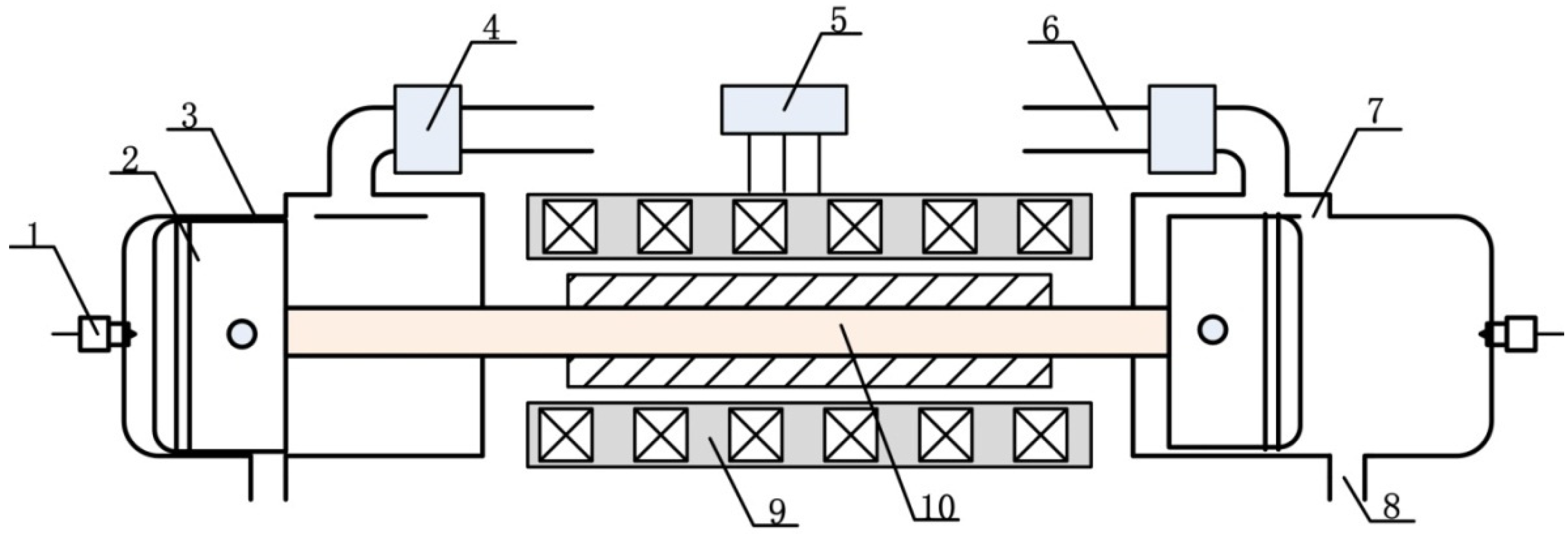
2.1. Prototype Configuration

According to the work in the literature, the FPELG has three typical types, such as the single-cylinder single-piston type, the dual-cylinder dual-piston type and the dual-piston type [1]. By comparing three typical types of the FPELG with relatively comprehensive performances; it is found that the dual-piston dual-cylinder type has a higher power to weight ratio and less mechanical components. Hence, the dual-cylinder dual-piston type FPELG is adopted in this research. The main structure of the dual-cylinder dual-piston type FPELG prototype is shown in Figure 1, and the main parameters are summarized in Table 1.

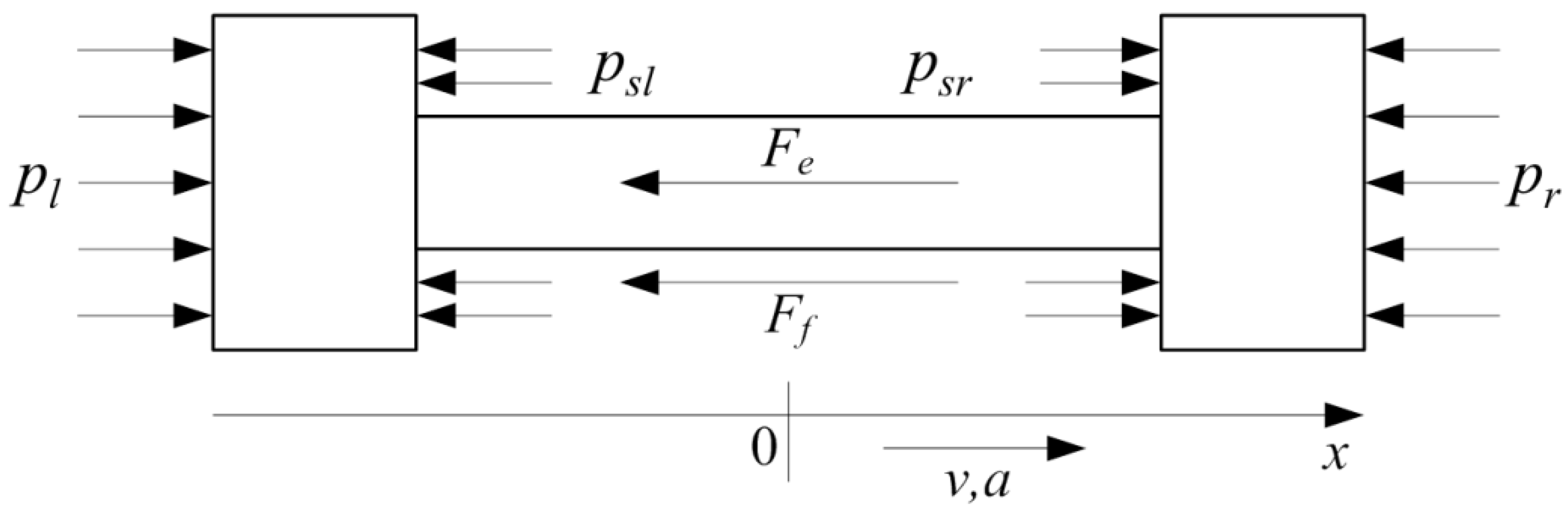
2.2. System Dynamic Model

In order to investigate the operation characteristics and the performance of the dual-cylinder dual-piston type FPELG adopting gasoline with hydrogen as the fuel input, the simulation models were established based on Newton’s Second Law. The forces acting on the mover of the FPELG during the generating process are shown in Figure 2.
Note, pl and pr are the in-cylinder gas pressure of the left and right side, respectively, psl and psr are the scavenging box gas pressure of the left and right side, respectively, Ff is the whole friction force and Fe is the electric force of the linear generator [7]. The scavenging box gas pressure of the left and right are the same, then the joint force from the scavenging box gas pressure is zero [5]. Thus, the mover dynamics equation is derived as follows:
m d 2 x d t 2 = A ( p l p r ) F f F e
where m is the mass of the mover, x is the mover displacement, t is time, A is the top area the piston, d 2 x d t 2 is the mover acceleration [1].
Refer to the previous papers [1,5], the all friction force Ff, and the electric force Fe could be described as follows, respectively:
{ F f = C f d x d t F e = k f k ε 1 R S + R L + j L d x d t
where Cf is the friction coefficient of the FPELG, d x d t is the mover velocity, kf is the constant thrust coefficient of the linear generator, kε is the coefficient of the electromotive force of the linear generator, Rs is the internal resistance of the generator, RL is the resistance of the external load, and L is the inductance of the linear generator [1].
Based on the operation principle of the FPELG, the thermodynamics process of the free-piston engine in the left cylinder is the same as that of the right cylinder. Therefore, the in-cylinder gas pressure (including the left in-cylinder gas pressure and the right in-cylinder gas pressure) of each combustion chamber is derived as follows [4]:
d p d t = γ 1 V ( d Q c d t d Q h d t ) γ p V d V d t - γ p m g a s d m g a s d t
where p is the in-cylinder gas pressure, γ is the ratio of heat capacities, V is the instantaneous cylinder volume, Qc is the heat released from the combustion process, Qh is the heat transferred to the cylinder wall, mgas is the in-cylinder gas mass [1,5].
As for the heat transfer process of the free-piston engine, it was found that the major influence on the heat transfer characteristics is the in-cylinder gas charge temperature and the flow pattern of the cycle [4,37]. Therefore, according to the previous papers, the heat transfer process is derived as follows:
{ d Q h d t = h A c y l ( T T w ) h = 130 V 0.06 ( p ( t ) 10 5 ) 0.8 T 0.4 ( v p + 1.4 ) 0.8
where h is the heat transfer coefficient, Acyl is the area of the in-cylinder surface in contact with the gas, Tw is the average temperature of the cylinder wall, and vp is the mover average speed [1].
As for the gas leakage characteristics of the free-piston engine, refer to our previous paper, the gas leakage mass is derived as follows:
d m a i r d t = { C e × A l e a k a g e ( R T 0 ) 0.5 p ( t ) [ p s p ( t ) ] 1 γ { 2 γ γ 1 [ 1 ( p s p ( t ) ) γ 1 γ ] } 0.5 p s p ( t ) > ( 2 γ + 1 ) γ γ 1 C e × A l e a k a g e ( R T 0 ) 0.5 p ( t ) γ 1 2 ( 2 γ + 1 ) γ + 1 2 ( γ 1 ) p s p ( t ) ( 2 γ + 1 ) γ γ 1
where Ce is the discharge coefficient, Aleakage is the leakage area, T0 is assumed to the ambient temperature, ps is the gas pressure in the pumping box [1].
As for the combustion process of the FPELG, the Wiebe function based on the time is applied on the mass fraction burned, and is derived as follows [1]:
d Q c d t = a b + 1 C d ( t t s C d ) b exp ( a ( t t s C d ) b + 1 ) Q i n
where a and b are parameters in the Wiebe function, respectively, the value of a is 5, and the value of b is 2. Cd is the combustion duration, ts is the start timing during the combustion process, Qin is the overall heat input in each cycle [1].
In order to investigate the piston dynamics characteristics and the performance of the FPELG adopting gasoline with hydrogen as the fuel, the fraction of the hydrogen volume to the total intake gas volume varied. Based on the hydrogen characteristics, the burning limit of hydrogen fuel in the air is from 4.5% to 75% (the fraction of the hydrogen volume). In order to prevent the backfire phenomenon from happening, the fraction of the hydrogen volume to the total intake gas volume must be below 4.5%, according to [36]. Thus, the fraction of the hydrogen volume to the total intake gas volume is set from 0% to 4.5% in 1.5% intervals. The fraction of hydrogen volume to the total intake gas volume is defined as follows:
α H 2 = V H 2 V i n t a k e
where α H 2 is the volume rate of hydrogen to the total intake gas volume in each cycle (it is set to 0%, 1.5%, 3.0%, and 4.5%, respectively, in this paper), V H 2 is the intake hydrogen volume in each cycle, V i n t a k e is the intake volume (working volume) at the end of the intake process, and is constant in each cycle.
Therefore, the input energy from gasoline with hydrogen mixed fuel in each cycle is derived as follows:
{ Q i n = Q g a s o + Q H 2 Q g a s o = m g a s o L g a s o Q H 2 = m H 2 L H 2
where Q i n is the total input energy from gasoline fuel and hydrogen fuel, Q g a s o is the total input energy from gasoline fuel, Q H 2 is the total input energy from hydrogen fuel, m g a s o is the gasoline mass in each cycle, L g a s o is the low heating value of gasoline, m H 2 is the hydrogen mass in each cycle, and L H 2 is the low heating value of hydrogen.
The energy from hydrogen in each cycle is derived as follows:
Q H 2 = m H 2 L H 2 = α H 2 ρ H 2 V i n t a k e L H 2
where ρ H 2 is the density of hydrogen.
According to the above analyses, the air mass for gasoline-fuel during the combustion under stoichiometric combustion is derived as follows:
m a i r _ g a s o = ( 1 α H 2 ) V i n t a k e ρ a i r α H 2 ρ H 2 V i n t a k e φ H 2
where mair-gaso is air mass for gasoline-fuel during the combustion under stoichiometric combustion, ρ a i r is the air density, φ H 2 is the air-fuel ratio of hydrogen, and is set to 34.3 in this paper.
The energy from gasoline-fuel in each cycle is derived as follows:
Q g a s o = m g a s o L g a s o = m a i r _ g a s o φ g a s o L g a s o = ( 1 α H 2 ) V int a k e ρ a i r α H 2 ρ H 2 V i n t a k e φ H 2 φ g a s o L g a s o
where φ g a s o is the air-fuel ratio of gasoline, and is set to 14.7.
In order to obtain the precise performance of the FPELG adopting gasoline with hydrogen as fuel, an accurate description of the combustion process is essential. Thus, as for the combustion process of the FPELG adopting gasoline blend with hydrogen as fuel, a coupling iterative calculation was carried out. The coupling iterative calculation process is shown in Figure 3, and the detailed procedure is explained as follows:
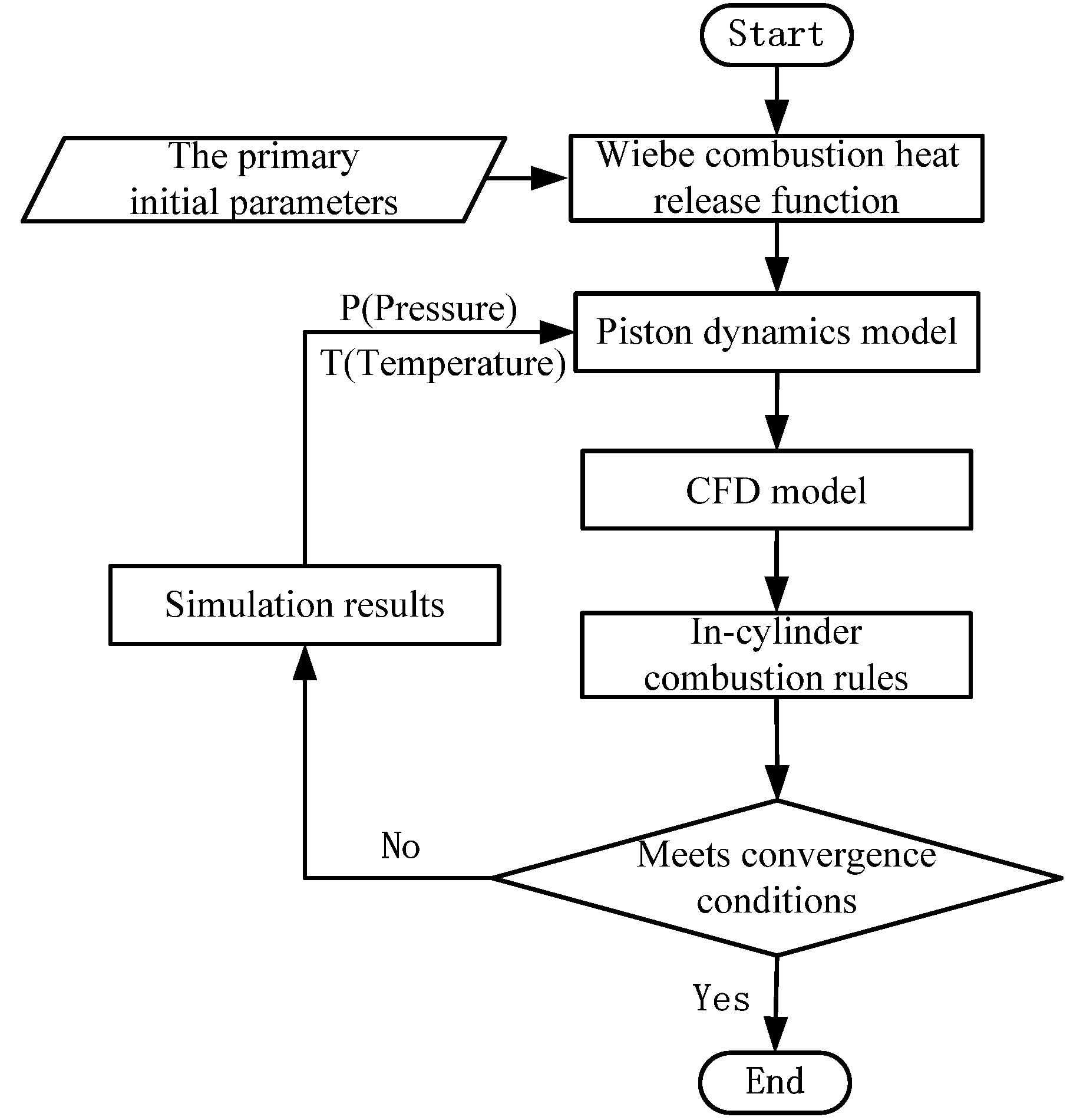
  • According to the initial parameters and the Wiebe function, the piston operation rules can be obtained by the zero-dimensional dynamic model, as the above system dynamic model illustration.
  • Based on the piston operation rules from step 1, the CFD model of the combustion process is set up by the piston displacement, and it is used to calculate the in-cylinder heat release process.
  • Based on step 2, the simulation results of the in-cylinder heat release process are returned to the combustion process of the dynamic piston model, and replace the Wiebe function (including the in-cylinder pressure and temperature in the zero-dimension model), then the piston operation profile is updated.
  • Based on step 3, the CFD model of the combustion process is re-established according to the updated piston operation profile, and it is used to re-calculate the in-cylinder heat release process.
  • Repeat step (2), step (3), and step (4) until they meet the iterative convergence conditions (The difference of the in-cylinder pressures achieved from the zero-dimension calculation results, and the CFD calculation results were less than 5%, according to the previous paper [7]).

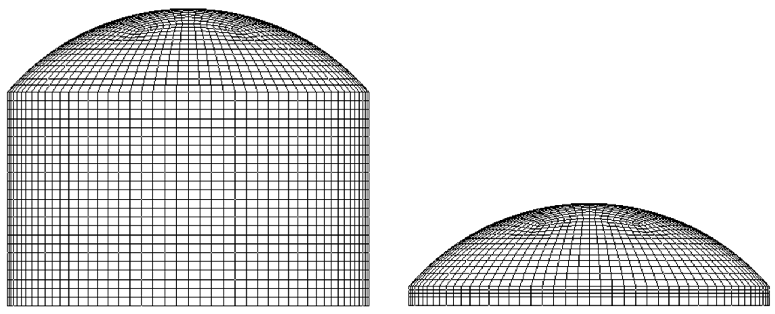
2.3. System CFD Model

According to the computational mesh model, the whole domain contained 43,392 cells, including 43,104 hexahedron cells and 288 prism cells, as shown in Figure 4. In addition, the equivalent crank angel was adopted during the CFD combustion simulation process because the FPELG lacks the crankshaft mechanism. Besides, the operation frequency was replaced with the equivalent speed. Based on the abovementioned, the initial boundary conditions of the coupling iterative calculation process were listed in Table 2.
The combustion process of the FPELG adopting gasoline with hydrogen as the fuel is the turbulent combustion process [38]. According to the engine turbulent combustion characteristics, the extended coherent flame model (ECFM) was applied on the FPELG under spark-ignited combustion mode with the premixed charge [39]. As for the simulation combustion process, there are many mathematical models provided in Fire Simulation software. In addition, the k-zeta-f sub-model was adopted to describe the turbulent flow in the cylinder, and the momentum equation employed the MINIMOD relaxed scheme for discretization [40,41].

3. Simulation Results and Discussion

3.1. Different Hydrogen Volume Fraction

According to the research on the conventional ICEs [42,43], different performances will be achieved when different fuels are adopted. Therefore, the mover operation characteristics and the performance of the gasoline FPELG with various hydrogen volume fractions increases from 0% to 4.5% in intervals of 1.5% are compared in this section. The hydrogen volume fraction is the only variable, while the other parameters values are the same, and the equivalence ratio is set to 1.
One complete operation cycle of the mover displacement with different hydrogen volume fractions are compared in Figure 5 and Figure 6. As for Figure 5, it is found that all the mover displacement profiles with different hydrogen volume fractions are similar to that of a constant amplitude and frequency oscillation system [2]. As the operation principles of the gasoline FPELG with various hydrogen volume fractions are the same, the mover operation characteristics are similar. However, it is noted that both the piston TDC and the system operating frequency are different when different hydrogen volume fractions are applied. Moreover, the piston TDC and the engine frequency are decreased when the hydrogen fractions change from 0% to 4.5% in intervals of 1.5%. According to the characteristics of hydrogen, it has a much lower energy density than gasoline on a volume basis. When the free-piston engine of the FPELG is operated at a stoichiometric condition, the air volume in the intake process is gradually reduced when the hydrogen volume fraction increases. So the gasoline mass of each cycle is reduced when the air volume is reduced. Therefore, the total input energy of each cycle is reduced with the hydrogen volume fraction increases from 0% to 4.5%, under fixed ignition timing and at stoichiometric conditions. Therefore, both the piston TDC and the system operating frequency are reduced as the hydrogen volume fraction increases.
Figure 6 presents the mover displacement versus the velocity profile of the gasoline FPELG under the different hydrogen volume fractions. The ignition timing is fixed regardless of the different hydrogen volume fractions and the free-piston engine operates at the stoichiometric condition. It is apparent that the mover velocity changes significantly after the piston TDC, and the mover velocity is highest when the purity of gasoline is applied. Since the total input energy of pure gasoline is higher than that when gasoline with hydrogen is applied, the mover peak velocity and the piston TDC vary in a negative correlation with the hydrogen volume fraction.
Figure 7 illustrates the pressure versus volume diagram when different hydrogen volume fractions are applied. It is found that the heat release process of the FPELG is similar to a constant volume process, although the hydrogen volume fractions are different. However, a higher hydrogen volume fraction leads to a higher degree of the constant volume combustion process, and it means that the free-piston engine operation process is closer to the ideal cycle when the hydrogen volume fraction increases [42]. Therefore, the indicated thermal efficiency is positively correlated with the increase in hydrogen volume fraction.
Meanwhile, the peak in-cylinder gas pressure increases the hydrogen volume fraction. The adiabatic flame speed (237 cm/s) of hydrogen is five times as fast as that of gasoline (42 cm/s), and the diffusion coefficient (0.61 cm2/s) of hydrogen is four times as fast as that of the gasoline (0.16 cm2/s), according to the hydrogen combustion performance [42]. Due to the stoichiometric combustion and fixed ignition timing, the gasoline-hydrogen mixture fuel combusts in a shorter duration than the pure gasoline fuel, the high flame speed of hydrogen leads to a sharp increase in peak in-cylinder gas pressure. Then the peak in-cylinder gas pressure of the gasoline FPELG under the gasoline-hydrogen mixture fuel is higher than that of the purity gasoline fuel.
The free-piston engine performances of the FPELG are shown in Table 3 when the different hydrogen volume fractions are applied. From Table 3, it is found that with the hydrogen volume fraction increases, the peak in-cylinder gas pressure also increases from about 49.5 bar at α H 2 = 0 to 54.5 bar at α H 2 = 4.5 % , the peak mover velocity decreases from 5.0 m/s at α H 2 = 0 to 4.9 m/s at α H 2 = 4.5 % . The peak in-cylinder gas pressure is positively correlated with the hydrogen volume fraction, as hydrogen has faster flame speed and shorter combustion duration. However, the peak mover velocity and the equivalent speed are in negative correlation with the hydrogen volume fraction, due to the decrease in the total input energy when the hydrogen volume fraction increases. However, the free-piston engine indicated efficiency (the calculating process was showed in reference [5]) is increased from 32.3% at α H 2 = 0 to 35.3% at α H 2 = 4.5 % from Table 3. As the gasoline-hydrogen mixed fuel has a faster burning speed and shorter combustion duration, the heat release process of the free-piston engine is more similar to a constant volume heat release process. Meanwhile, the in-cylinder gas pressure drops more quickly; it means that the post-combustion duration of the free-piston engine is reduced when the hydrogen volume increases. The shorter the post-combustion duration, the less fuel is burnt during the expansion process, and the smaller amount of exhaust loss. Thus the free-piston engine indicated efficiency is further increased as the hydrogen volume fraction increases.

3.2. Different Ignition Timing

According to the conventional ICEs, it is found that the ignition timing is one of the significant parameters to the performance of the spark-ignition engine. For the spark-ignition FPELG adopting gasoline with hydrogen as fuel, different ignition timing is supposed to play an important role in its performance. In order to compare the mover operation characteristics and the performance of the gasoline-hydrogen mixed fuel FPELG with different ignition timings, the ignition timing was the only variable, and the other parameter values remained the same. The equivalence ratio was set to 1, and the hydrogen volume fraction ( α H 2 ) was set to 3%. Due to the elimination of the crankshaft mechanism of the FPELG, the mover displacement was used as a feedback signal to decide the ignition timing. According to the previous paper, the equivalent ignition timing in the crank angle was derived as follows [2]:
Δ x i g n S = Δ θ i g n 180
where Δ x i g n is the distance before the TDC when the ignition timing of the FPELG; S is the stroke of the FPELG, S is 2 in this paper, and Δ θ i g n is the equivalent ignition timing advance [21].
Therefore, a series of equivalent ignition timings in the crank angle of 14 ° , 16 ° , 18 ° , and 20 ° (5.4 mm, 6.2 mm, 7.0 mm, and 7.8 mm from the cylinder head, respectively) are simulated to investigate its influence on the free-piston engine performances. According to the results, extremely high in-cylinder pressure is achieved under an equivalent ignition timing of 14 ° and the hydrogen volume fraction is set to 3%, which induces engine knocking and is supposed to be avoided. Thus, the engine performances were not investigated when the equivalent ignition timing was 14 ° .
From Figure 8a, it is found that with the increase in ignition timing advance, the piston TDC of the FPELG was decreased because the earlier ignition timing would lead to earlier changes in the piston motion direction and a shorter duration during the compression process. As shown in Figure 8b, with the increase in the ignition timing advance, the peak mover velocity decreased. The changing trend of the peak in-cylinder gas pressure with the ignition timing advance was the same as the peak piston velocity, as shown in Figure 8c. The peak in-cylinder gas pressure could reach 54 bar when the ignition timing advance was 16 ° and the hydrogen volume fraction wass set to 3%. The heat release process of the FPELG was closer to a constant volume combustion process with later ignition timing, and the area enclosed by the P-V diagram was larger, as shown in Figure 9. As a result, the indicated work by the FPELG was higher with later ignition timing. According to the above discussion, the ignition timing is supposed to be a potential variable for the future stable operation of the control system.
As seen in Figure 10, the engine indicated efficiency is increased when the equivalent degree changes from 20 ° to 16 ° (the ignition timing chaned from 7.8 mm to 6.2 mm from the cylinder head) regardless of the hydrogen volume fraction. This is because of the heat release process of the FPEL, which is closer to a constant volume combustion process with later ignition timing. The free-piston engine indicated efficiency with gasoline is lower than that with the gasoline-hydrogen mixed fuel, and it is in the same changing trend to the discussion results above.

4. Conclusions

This paper focused on the performance of the FPELG adopting gasoline with hydrogen as fuel. The method of coupling a zero-dimensional dynamics model with a multi-dimensional CFD combustion model was applied during the simulation process. The piston dynamics characteristics and the performances of the FPELG with various hydrogen volume fractions in the total intake gas volume and the different ignition timing were investigated separately. The results indicated that:
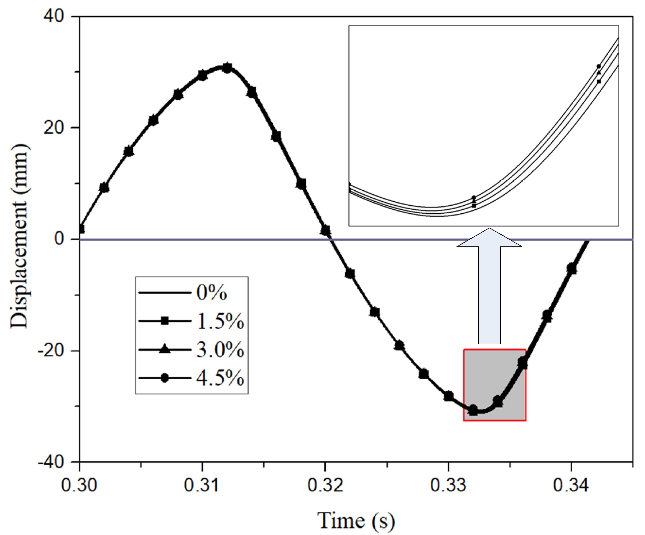
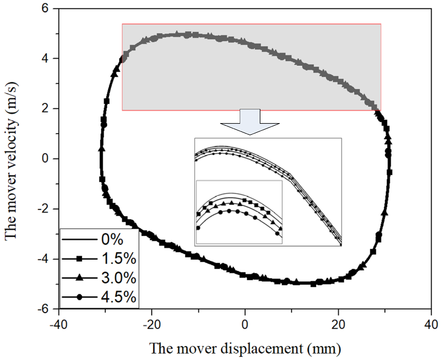
  • It was observed that all the piston displacement profiles with different hydrogen volume fractions are similar to that of a constant amplitude and frequency oscillation system, regardless of the hydrogen volume fractions in the total intake gas volume. However, the piston TDC, the peak piston velocity, and the operation frequency of the FPELG are decreased when the hydrogen fractions change from 0% to 4.5%. Since the total input energy of each cycle is reduced as the hydrogen volume fraction increases, the FPELG operated under fixed ignition timing and at stoichiometric conditions.
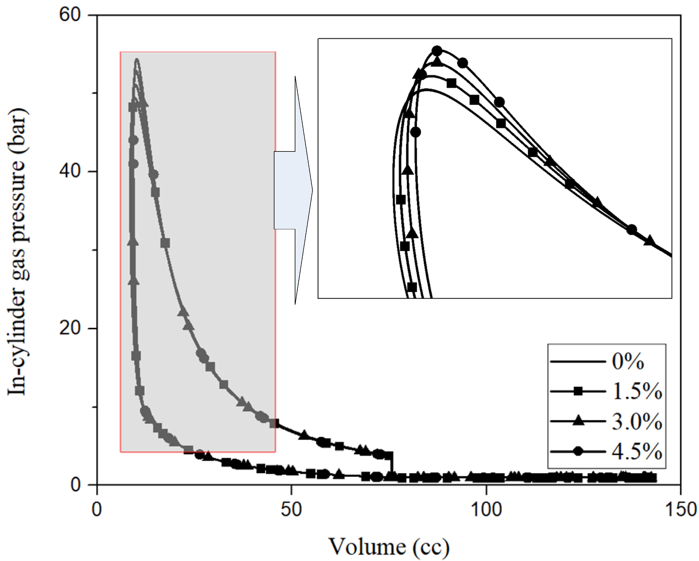
  • The peak in-cylinder gas pressure is in a positive correlation with the hydrogen volume fraction increase, due to the fast flame speed and short combustion duration of the hydrogen fuel. Meanwhile, the indicated thermal efficiency of the free-piston engine is increased from 32.3% to 35.3% with the hydrogen volume ratio changes from 0% to 4.5%, when the free-piston engine operates at stoichiometric conditions with fixed ignition timing. As the higher hydrogen volume fraction leads to a higher degree of constant volume during the combustion process and means that the operation process of the free-piston engine is closer to the ideal cycle when the hydrogen volume fraction increases.
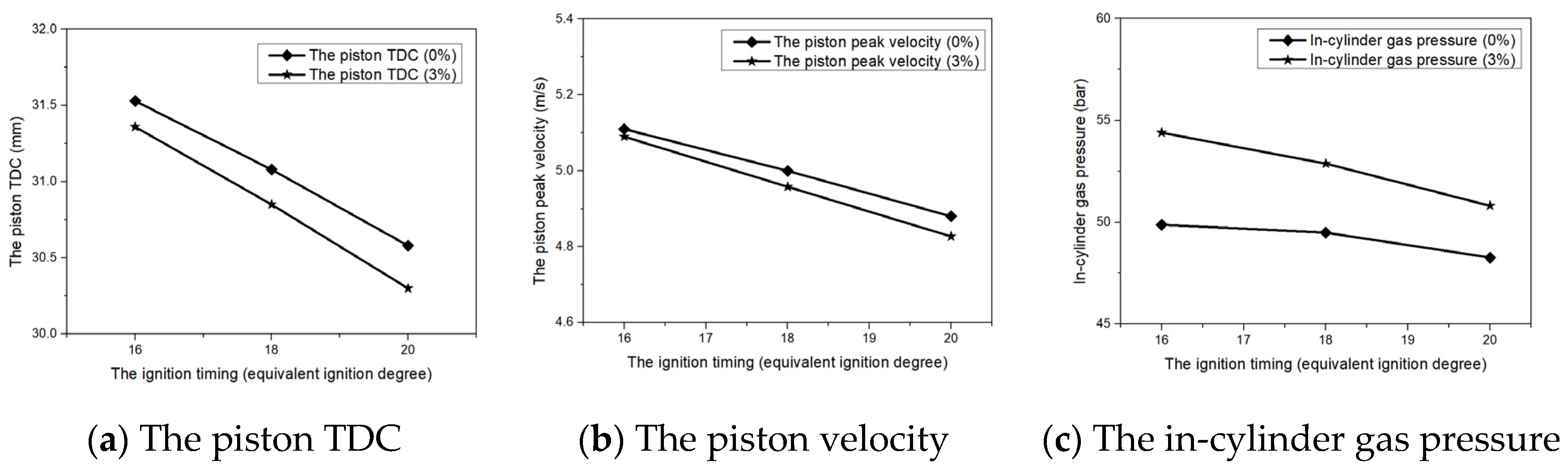
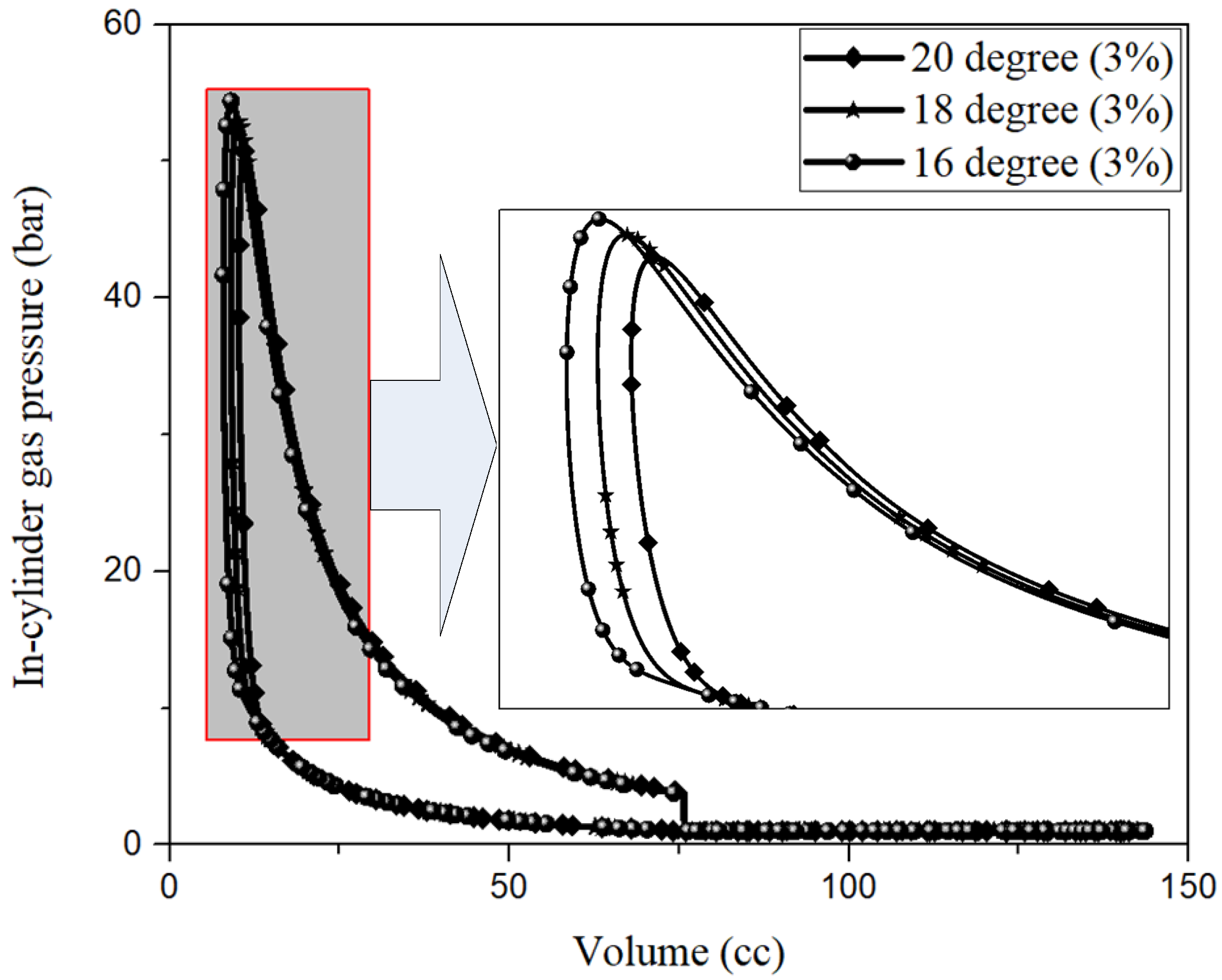
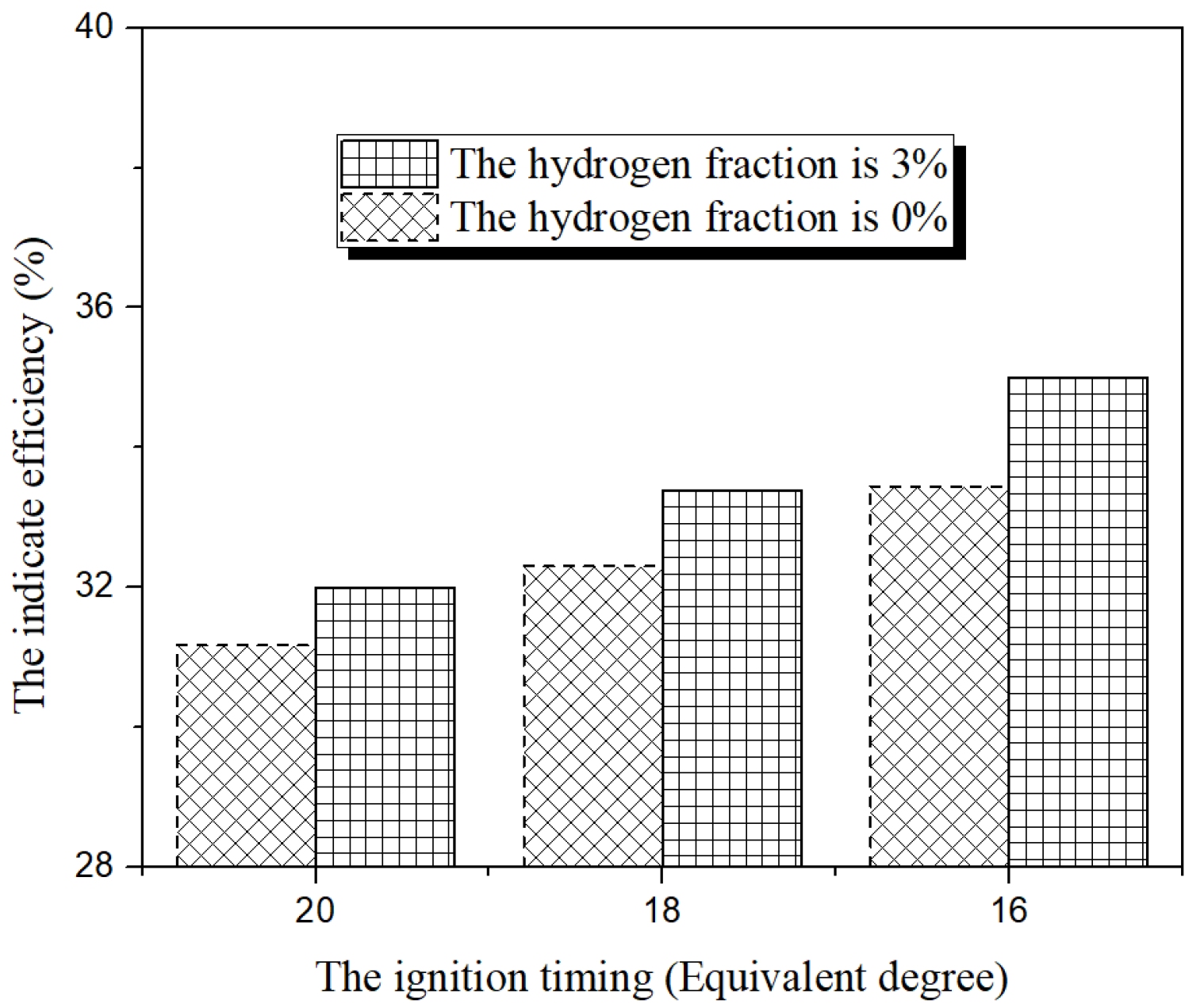
  • The ignition timing advance increases, the piston TDC is decreased. The peak piston velocity and the peak in-cylinder gas pressure are in negative correlation with the ignition timing advance. The indicated thermal efficiency of the free-piston engine is increased with the equivalent degree of ignition timing advance from 20 ° to 16 ° regardless of the hydrogen volume fraction. Therefore, the ignition timing of the FPELG under the SI combustion mode is supposed to be an effective and practical control variable for the future stable operation control system.

Author Contributions

Conceptualization, Z.Z. (Ziwei Zhang), H.F. and Z.Z. (Zhengixng Zuo); methodology, Z.Z. (Ziwei Zhang); software, Z.Z. (Ziwei Zhang); validation, Z.Z. (Ziwei Zhang), H.F. and Z.Z. (Zhengixng Zuo); formal analysis, Z.Z. (Ziwei Zhang), H.F. and Z.Z. (Zhengixng Zuo); investigation, Z.Z. (Ziwei Zhang), H.F. and Z.Z. (Zhengixng Zuo); resources, H.F. and Z.Z. (Zhengixng Zuo); data curation, Z.Z. (Ziwei Zhang), H.F. and Z.Z. (Zhengixng Zuo); writing—original draft preparation, Z.Z. (Ziwei Zhang); writing—review and editing, Z.Z. (Ziwei Zhang), H.F. and Z.Z. (Zhengixng Zuo); supervision, Z.Z. (Ziwei Zhang), H.F. and Z.Z. (Zhengixng Zuo); project administration, H.F. and Z.Z. (Zhengixng Zuo); funding acquisition, H.F. and Z.Z. (Zhengixng Zuo). All authors have read and agreed to the published version of the manuscript.

Funding

This project is supported by the National Nature Science Foundation of China (51675043) and Program of Introducing Talents of Discipline to Universities of China (B12022). We would like to thank the sponsors.

Conflicts of Interest

The authors declare no conflict of interest.

Nomenclature

CFDComputational fluid dynamics
EMFBack electromotive force
FPELGFree piston engine linear generator
FPEFree-piston engine
FPECFree-piston energy convertor
ICEsInternal combustion engines
HCCIHomogeneous charge compression ignition
PCCIPremixed charged compression ignition
SISpark ignition
TDCTop dead left
AThe top area the piston (m2)
AcylThe area of the in-cylinder surface in contact with the gas (m2)
AleakageThe leakage area (m2)
a5
b2
CdCombustion duration (s)
CDThe discharge coefficient (-)
CfCoefficient friction (-)
FfFriction force (N)
FeThe electric load force of the generator (N)
hThe coefficient of heat transfer (-)
kfThrust coefficient of the force constant (N/A)
kεCoefficient of the electromotive force of the generator (V/m/s)
LInductance of the generator (H)
L g a s o The low heating value of gasoline (J/kg)
L H 2 The low heating value of hydrogen (J/kg)
mMoving mass (kg)
mair-gasoAir mass for gasoline fuel (kg)
m g a s o The gasoline mass in each cycle (kg)
m H 2 The hydrogen mass in each cycle (kg)
mgasIn-cylinder gas mass (kg)
pIn-cylinder gas pressure (bar)
plIn-cylinder gas pressure in the left cylinder (bar)
prIn-cylinder gas pressure in the right cylinder (bar)
PsThe gas pressure in the pumping box (bar)
pslScavenging box gas pressure of the left (bar)
psrScavenging box gas pressure of the right (bar)
Q g a s o The total input energy from gasoline (J)
Q H 2 The total input energy from hydrogen (J)
QhHeat transferred to the cylinder wall (J)
QcHeat released from the combustion process (J)
RSResistance of the coil (Ω)
RLResistance of the external load (Ω)
T0The air temperature (K)
TwThe average surfaces temperature of the cylinder wall (K)
vpThe average mover speed (m/s)
VInstantaneous cylinder volume (m3)
V H 2 The intake hydrogen volume in each cycle (m3)
V i n t a k e The intake volume (working volume) at the end of intake process (m3)
xPiston displacement (m)
tsThe start timing during the combustion process (s)
QinThe overall heat input in each cycle (J)
d 2 x / d t 2 The mover acceleration (m/s2)
d x / d t The mover velocity (m/s)
γRatio of heat capacities (-)
ρ a i r Air density (kg/m3)
ρ H 2 Hydrogen density (kg/m3)
φ g a s o Air fuel ratio of gasoline (-)
α H 2 The volume rate of hydrogen to the total intake gas volume in each cycle (-)
φ H 2 Air fuel ratio of hydrogen (-)

References

  1. Chendong, G.; Zuo, Z.; Jia, B.; Ziwei, Z.; Huihua, F.; Roskilly, A. Parametric analysis of a dual-piston type free-piston gasoline engine linear generator. Energy Procedia 2019, 158, 1431–1436. [Google Scholar] [CrossRef]
  2. Jia, B.; Smallbone, A.; Zuo, Z.; Feng, H.; Roskilly, A.P. Design and simulation of a two- or four-stroke free-piston engine generator for range extender applications. Energy Convers. Manag. 2016, 111, 289–298. [Google Scholar] [CrossRef]
  3. Guo, C.; Zuo, Z.; Feng, H.; Jia, B.; Roskilly, T. Review of recent advances of free-piston internal combustion engine linear generator. Appl. Energy 2020, 269, 115084. [Google Scholar] [CrossRef]
  4. Jia, B.; Zuo, Z.; Tian, G.; Feng, H.; Roskilly, A. Development and validation of a free-piston engine generator numerical model. Energy Convers. Manag. 2015, 91, 333–341. [Google Scholar] [CrossRef]
  5. Feng, H.; Guo, C.; Jia, B.; Zuo, Z.; Guo, Y.; Roskilly, T. Research on the intermediate process of a free-piston linear generator from cold start-up to stable operation: Numerical model and experimental results. Energy Convers. Manag. 2016, 122, 153–164. [Google Scholar] [CrossRef]
  6. Mikalsen, R.; Roskilly, A.P. A review of free-piston engine history and applications. Appl. Therm. Eng. 2007, 27, 2339–2352. [Google Scholar] [CrossRef] [Green Version]
  7. Feng, H.; Guo, C.; Yuan, C.; Guo, Y.; Zuo, Z.; Roskilly, A.P.; Jia, B. Research on combustion process of a free piston diesel linear generator. Appl. Energy 2016, 161, 395–403. [Google Scholar] [CrossRef]
  8. Nandkumar, S. Two-Stroke Linear Engine; West Virginia University Libraries: Morgantown, WV, USA, 2019. [Google Scholar]
  9. Goertz, M.; Peng, L. Free Piston Engine Its Application and Optimization; SAE Technical Paper 2000-01-0996; SAE International: Warrendale, PA, USA, 2000. [Google Scholar]
  10. Mao, J.; Zuo, Z.; Feng, H. Parameters coupling designation of diesel free-piston linear alternator. Appl. Energy 2011, 88, 4577–4589. [Google Scholar] [CrossRef]
  11. Pescara, R.P. Motor Compressor Apparatus. U.S. Patent 1,657,641, 31 January 1928. [Google Scholar]
  12. Jia, B.; Tian, G.; Feng, H.; Zuo, Z.; Roskilly, A. An experimental investigation into the starting process of free-piston engine generator. Appl. Energy 2015, 157, 798–804. [Google Scholar] [CrossRef]
  13. Atkinson, C.M.; Petreanu, S.; Clark, N.N.; Atkinson, R.J.; McDaniel, T.I.; Nandkumar, S.; Famouri, P. Numerical Simulation of a Two-Stroke Linear Engine-Alternator Combination; SAE Technical Paper 1999-01-0921; SAE International: Warrendale, PA, USA, 1999. [Google Scholar]
  14. Famouri, P.; Cawthorne, W.R.; Clark, N.; Nandkumar, S.; Atkinson, C.; Atkinson, R.; McDaniel, T.; Petreanu, S. Design and testing of a novel linear alternator and engine system for remote electrical power system. In Proceedings of the Power Engineering Society 1999 Winter Meeting, New York, NY, USA, 31 January–4 February 1999. [Google Scholar]
  15. William, C.; Parviz, F.; Nigel, C. Integrated Design of Linear Alternator/Engine System for HEV Power Unit. In Proceedings of the IEMDC 2001. IEEE International Electric Machines and Drives Conference, Cambridge, MA, USA, 17–20 June 2001; pp. 267–274. [Google Scholar]
  16. Shoukry, E.F. Numerical Simulation for Parametric Study of a Two-Stroke Compression Ignition Direct Injection Linear Engine. SAE Trans. 2002, 111, 2297–2308. [Google Scholar]
  17. Bade, M.; Clark, N.; Famouri, P.; Guggilapu, P. Feasibility of Multiple Piston Motion Control Approaches in a Free Piston Engine Generator; SAE Technical Paper 2019-01-2559; SAE International: Warrendale, PA, USA, 2019. [Google Scholar]
  18. Goldborough, S.S.; Blarigan, P.V. A Numerical Study of a Free Piston IC Engine Operating on Homogeneous Charge Compression Ignition Combustion. SAE Trans. 1999, 108, 959–972. [Google Scholar]
  19. Blarigan, P.V. Advanced internal combustion engine research. In Proceedings of the 2000 DOE Hydrogen Program Review, San Ramon, CA, USA, 9–11 May 2000. NREL/CP-570-28890. [Google Scholar]
  20. Van Blarigan, P.; Paradiso, N.; Goldsborough, S. Homogeneous Charge Compression Ignition with a Free Piston: A New Approach to Ideal Otto Cycle Performance; SAE Technical Paper 982484; SAE International: Warrendale, PA, USA, 1998. [Google Scholar]
  21. Blarigan, P.V. Developing a Thermodynamic Fuel Cell; Sandia National Laboratories: Washington, DC, USA, 2003. [Google Scholar]
  22. Fredriksson, J.; Denbratt, I. Simulation of a Two-Stroke Free Piston Engine; SAE Technical Paper Series 2004-01-1871; SAE International: Warrendale, PA, USA, 2004. [Google Scholar]
  23. Fredriksson, J.; Bergman, M.; Golovitchev, V.I. Modeling the Effect of Injection Schedual Change on Free Piston Engine Operation; SAE Technical Paper Series 2006-01-0449; SAE International: Warrendale, PA, USA, 2006. [Google Scholar]
  24. Chiang, C.-J.; Yang, J.-L.; Lan, S.-Y.; Shei, T.-W.; Chiang, W.-S.; Chen, B.-L. Dynamic modeling of a SI/HCCI free-piston engine generator with electric mechanical valves. Appl. Energy 2013, 102, 336–346. [Google Scholar] [CrossRef]
  25. Hung, N.B.; Lim, O.; Iida, N. The effects of key parameters on the transition from SI combustion to HCCI combustion in a two-stroke free piston linear engine. Appl. Energy 2015, 137, 385–401. [Google Scholar] [CrossRef]
  26. Kosaka, H.; Akita, T.; Moriya, K.; Goto, S.; Hotta, Y.; Umeno, T.; Nakakita, K. Development of Free Piston Engine Linear Generator System Part 1—Investigation of Fundamental Characteristics; SAE Technical Paper Series 2014-01-1203; SAE International: Warrendale, PA, USA, 2014. [Google Scholar]
  27. Goto, S.; Moriya, K.; Kosaka, H.; Akita, T.; Hotta, Y.; Umeno, T.; Nakakita, K. Development of Free Piston Engine Linear Generator System Part 2—Investigation of Control System for Generator; SAE Technical Paper Series 2014-01-1193; SAE International: Warrendale, PA, USA, 2014. [Google Scholar]
  28. Mikalsen, R.; Roskilly, A.P. The control of a free-piston engine generator. Part 1: Fundamental analyses. Appl. Energy 2010, 87, 1273–1280. [Google Scholar] [CrossRef] [Green Version]
  29. Mikalsen, R.; Roskilly, A.P. The control of a free-piston engine generator. Part 2: Engine dynamics and piston motion control. Appl. Energy 2010, 87, 1281–1287. [Google Scholar] [CrossRef] [Green Version]
  30. Mikalsen, R.; Roskilly, A.P. The design and simulation of a two-stroke free-piston compression ignition engine for electrical power generation. Appl. Therm. Eng. 2008, 28, 589–600. [Google Scholar] [CrossRef] [Green Version]
  31. Mikalsen, R.; Roskilly, A.P. Performance simulation of a spark ignited free-piston engine generator. Appl. Therm. Eng. 2008, 28, 1726–1733. [Google Scholar] [CrossRef]
  32. Mikalsen, R.; Roskilly, A.P. Coupled dynamic–multidimensional modelling of free-piston engine combustion. Appl. Energy 2009, 86, 89–95. [Google Scholar] [CrossRef] [Green Version]
  33. Jia, B.; Smallbone, A.; Feng, H.; Tian, G.; Zuo, Z.; Roskilly, A. A fast response free-piston engine generator numerical model for control applications. Appl. Energy 2016, 162, 321–329. [Google Scholar] [CrossRef]
  34. Jia, B.; Zuo, Z.; Feng, H.; Tian, G.; Smallbone, A.; Roskilly, A. Effect of closed-loop controlled resonance based mechanism to start free piston engine generator: Simulation and test results. Appl. Energy 2016, 164, 532–539. [Google Scholar] [CrossRef]
  35. Jia, B.; Mikalsen, R.; Smallbone, A.; Zuo, Z.; Feng, H.; Roskilly, A.P. Piston motion control of a free-piston engine generator: A new approach using cascade control. Appl. Energy 2016, 179, 1166–1175. [Google Scholar] [CrossRef] [Green Version]
  36. Ji, C.W.; Wang, S.F.; Yan, H.; Deng, F.S.; Diao, H.L.; Liu, Y. Experiment on Combustion and Emissions Characteristics of an IC Engine Blended With Hydrogen. J. Beijing Univ. Technol. 2008, 34, 1326–1331. [Google Scholar]
  37. Heywood, J.B. Internal Combustion Engine Fundamentals; McGraw-Hill: New York, NY, USA, 1988. [Google Scholar]
  38. Yuan, C.; Jing, Y.; Liu, C.; He, Y. Effect of variable stroke on fuel combustion and heat release of a free piston linear hydrogen engine. Int. J. Hydrogen Energy 2019, 44, 20416–20425. [Google Scholar] [CrossRef]
  39. Colin, O.; Benkenida, A.; Angelberger, C. 3D Modeling of Mixing, Ignition and Combustion Phenomena in Highly Stratified Gasoline Engines. Oil Gas Sci. Technol. 2003, 58, 47–62. [Google Scholar] [CrossRef] [Green Version]
  40. Miao, Y.; Zuo, Z.; Feng, H.; Guo, C.; Song, Y.; Jia, B.; Guo, Y. Research on the Combustion Characteristics of a Free-Piston Gasoline Engine Linear Generator during the Stable Generating Process. Energies 2016, 9, 655. [Google Scholar] [CrossRef]
  41. Fontana, G.; Galloni, E.; Palmaccio, R.; Torella, E. Numerical and Experimental Analysis of Different Combustion Chambers for a Small Spark-Ignition Engine; SAE Technical Paper 2004-01-1998; SAE International: Warrendale, PA, USA, 2004. [Google Scholar]
  42. Ji, C.; Wang, S. Effect of hydrogen addition on the idle performance of a spark ignited gasoline engine at stoichiometric condition. Int. J. Hydrogen Energy 2009, 34, 3546–3556. [Google Scholar] [CrossRef]
  43. Xu, P.; Ji, C.; Wang, S.; Cong, X.; Ma, Z.; Tang, C.; Meng, H.; Shi, C. Effects of direct water injection on engine performance in engine fueled with hydrogen at varied excess air ratios and spark timing. Fuel 2020, 269, 117209. [Google Scholar] [CrossRef]
Figure 1. The main structure of the FPELG. (1) Spark plug (2) Piston (3) Cylinder (4) Fuel injector (5) External load (6) Air-intake tube (7) Scavenging port (8) Exhaust port (9) Stator (10) The connecting rod.
Energies 13 04685 g001
Figure 2. Forces acting on the mover of the FPELG.
Energies 13 04685 g002
Figure 3. The state flow diagram of the iterative calculation process.
Energies 13 04685 g003
Figure 4. Computational mesh for CFD model.
Energies 13 04685 g004
Figure 5. The mover displacement with different hydrogen volume fractions.
Energies 13 04685 g005
Figure 6. The mover displacement versus the velocity profile of the gasoline FPELG under different hydrogen volume fractions.
Energies 13 04685 g006
Figure 7. The pressure versus volume of the gasoline FPELG under different hydrogen volume fractions.
Energies 13 04685 g007
Figure 8. The piston TDC, peak velocity and the in-cylinder gas pressure under different ignition timing.
Energies 13 04685 g008
Figure 9. The pressure versus volume under different ignition timing and the hydrogen volume fraction is 3%.
Energies 13 04685 g009
Figure 10. The indicate efficiency under different ignition timing and the different volume fraction.
Energies 13 04685 g010
Table 1. Main parameters of the prototype.
ParametersValues
Bore (mm)52.5
Effective stroke (mm)34.0
Total stroke (mm)68.0
Piston and connecting rod mass (kg)5.0
The thrust force constant of the linear generator (N/A)74.4
Back EMF (Back electromotive force) constant (N/m/s)85.9
Coil resistance (Ω)14.0
External load resistance (Ω)28.0
Table 2. The initial parameters of the CFD combustion model.
ParametersValues
Exhaust port close (°ECA)80.0
Exhaust port open (°ECA)262.0
Ignition timing (°ECA)136.5
Ignition timing/Ignition position from cylinder head (mm)8.0
Air-intake temperature (K)300
Air-intake pressure (bar)1.2
Air-exhaust pressure (bar)1.0
Table 3. The engine performance parameters with different hydrogen volume fraction.
Blend   Fraction   α H 2 Piston TDC (mm)Peak In-Cylinder Pressure (Bar)Peak Velocity (m/s)Indicate Efficiency (-)
0%31.0749.465.032.3%
1.5%30.9651.174.9732.9%
3.0%30.8452.874.9433.8%
4.5%30.7054.424.9035.3%

