1. Introduction
The canned machine is usually applied in the chemical and nuclear field as a pump drive, to convey poisonous and high pressure liquid [
1,
2]. Poisonous, corrosive and high pressure liquid may get into the air gap, thus two metallic cans are respectively fixed in the air gap, which can prevent the leakage of transportable liquid. In this harsh working environment, high reliability ensures the shielding motor operates normally for a long time.
Electromagnetic shielding phenomenon is formed, this is due to the cans that are used in the air gap. The can is made up of the bulk metal instead of lamination, which is limited by the manufacturing craft. The shielding material is nonmagnetic and has low conductivity to suppress the eddy current, such as a nickel based alloy. In an alternating flux field, an eddy current induction occurs on the cans and generates a loss that is called can loss here. Meanwhile, the eddy induction also forms a flux field that affects the original one in return, as well as affects distinctly the output performance of the motors.
A traditional canned motor is mainly the squirrel cage induction motor [
3,
4,
5,
6]. However, the induction cage structure may break due to a higher temperature rise of rotor that is caused by can loss. In [
7], the number of stator slots is further increased to 48 and the double-layer armature coil structure is adopted to make the air gap magnetic field more sinusoidal, thereby reducing can loss. However, in the pumping industry, with increasing demand of high efficiency, reliability and control flexibility, canned permanent magnet motors are a good solution [
8,
9]. A high temperature rise of the rotor leads to interior permanent magnet synchronous motors demagnetizing, due to the poor cooling environment of the shielding motors, and thus the interior permanent magnet synchronous motors are not suitable for the shielding motor. The surface mounted PMs topology is investigated, which can be effective to avoid demagnetizing caused by excessive working temperature.
Fractional slot tooth concentrated windings (FSCW) have stimulated research interest [
10,
11]. This winding configuration shows shorter end winding, the higher fault tolerance rate, the lower manufacturing cost, the harder mechanical characteristics, and higher efficiency. Meanwhile, the windings have no overlap between each other, so the interphase insulation is well. However, in terms of the magneto motive force (MMF) contents, the air gap magnetic field of the permanent magnet synchronous motor is not sinusoidal, resulting in certain harmonics. Apart from the working harmonic that generates electromagnetic torque, the odd harmonics cause a lot of problems as vibration, noise and heat [
12,
13,
14]. A canned permanent magnet synchronous motor with FSCW is studied, with emphasis placed on can loss and the air gap flux field.
The electromagnetic shielding analysis is emphasized in the canned motor theoretical analysis. In [
15], the mechanism and characteristics of the eddy current induction and the loss of the DC canned motor under different excitation are studied. The main research methods of conventional motors include finite element (FE) [
16,
17,
18,
19], the analytical method [
20] and empirical formulas [
21,
22,
23]. The empirical formulas method uses arithmetic expression to estimate the loss as the corresponding function, which can quickly and roughly calculate the average value of the can loss. In [
24], the can loss is calculated by a multilayer analytical model. However, traditional analysis methods cannot directly be applied to canned motors, the eddy current and the can loss distribution in space, and the
vector decomposition of the eddy current is not well studied. In this paper, a canned permanent magnet synchronous motor is studied. The organization of the paper is as follows. In
Section 2, the studied canned PM motor is described. In
Section 3, the calculation method is introduced and the
vector decomposition of eddy induction and can loss is discussed. In
Section 4, the influence of the load angle on eddy induction and can loss distribution is analyzed. In
Section 5, can loss and flux harmonics due to rotor speed and load is studied.
2. The Canned PM Motor
In
Figure 1 a 2D sketch of the stator and rotor is shown, with an appropriate choice of the slot-pole that helps reduce copper consumption and loss. The motor is featured with concentrated coil, this typology exhibits: (1) a lower cogging effect and torque ripple, which are beneficial for the shielding motor to adjust the fluid at a low speed; (2) the higher fault tolerance rate, the lower production cost and the harder mechanical characteristics; (3) good manufacturability, simple off-line and higher copper space factor and (4) good interphase insulation. The motor adopts the stator split ratio design, which has stronger air gap flux density and lower yoke flux saturation.
The major dimensional parameters are listed in
Table 1. A couple of cans were fixed in the air gap, namely the stator can and rotor can. The rotor can was fixed onto the bore of the rotor part to protect the PMs from corrosion, meanwhile the stator can was fixed onto the inner surface of the stator teeth to protect the armature winding. To accommodate the cans and PMs, the air gap width with magnets reached to 9 mm. Due to the width of the air gap being artificially increased to install the cans, the mutual inductance could be ignored. To resist the centrifugal force, the radial width of cans reached up to 0.5 mm, which could be correspondingly increased for larger canned motors. The can material was Hastelloy C, a nickel-based nonmagnetic alloy with low electrical conductivity that restrains the eddy current. The value was 800,000
at 20 °C and approximately 1.4 times lower at every 100 °C rise. For the conductivity of both cans, the value at the steady-state temperature was preset. Due to that, the temperature rise on the can only affected the intensity of the eddy current and loss, but did not affect the characteristics of its distribution on cans, thus a conductivity change that was caused by the temperature rise was not considered in this paper. Note that the air gap flux field change was caused by the eddy current, and not by the magnetoresistance change that was caused by the material.
3. Field Distribution Analysis Method
For the can, the corresponding conductivity is given. To illustrate the mechanism of can loss, the multilayer analytical model was introduced. The motor can be regarded as a multilayer model with the corresponding boundary conditions between each layer, as to constitute the boundary conditions of Maxwell’s equations. The can loss was obtained by calculating the electromagnetic energy flow based on Poynting’s vector. The energy vector is defined as , H and is the magnetic field intensity and E is the electrical field density.
For the sinusoidal time-varying electromagnetic fields, the active power was the average power
. The energy vector caused by each harmonic was summed up, and thus can loss could be calculated by integrating the surface
of both cans layer, which can be written as
where
n is the unit vector vertical to
and the
r is the radius of each part of the motor components. When conducting detailed theoretical deduction, the mathematical model of can loss and conductivity is the linear model.
The eddy current and loss were calculated with FE by Maxwell in this paper. This method discretizes the solution region into many small subregions, applying the principle of solving the boundary problem to these subregions, and then the results of each subregion are summed up to get the solution of the whole region. For the FE model, all the motor segments were columnar and separated from each other. The cylinder was meshed to make the solution domain more circular and thus improve the calculation accuracy. Too many grids consumed too much of the solution time, so each cylinder was polygonized up to 180 sectors.
In this paper, using the direction method we calculated can loss, based on each mesh element
i with flux density
. Loss density
can be seen as a function of the square rate of change of
, which is
where the Steinmetz coefficient is represented by
a and
T means the time period. By discretizing Equation (2), we get
where
t is the time of two discretized units in a subregion and
n is the number of steps during
T. Then the can loss is written as
where
is the mass of
i-th element,
M is the total number of subregion and
f is the frequency.
A flux path with and without cans is shown in
Figure 2. The ideal 3-phase sinusoidal AC excitation with a rated load was applied. Through the stator teeth, yoke, air gap, PMs and rotor yoke, the main flux loop was formed and was similar in both motors. Due to the use of cans in the air gap that led to the eddy current induction and thus the magnetic energy consumption in the stator and rotor parts, the flux density was slightly reduced.
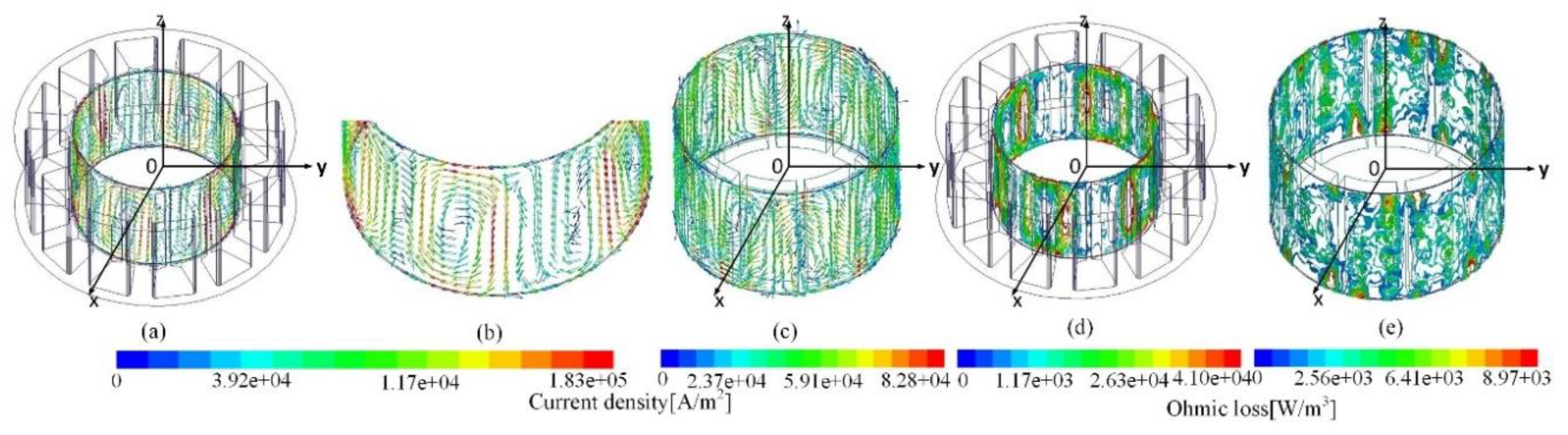
The eddy current and can loss on both cans were spatial and temporal distribution. An ideal working current could be decomposed into the axis current. As to both cans, the eddy current and can loss induced by different currents are shown, and the vector relationship of the eddy current and can loss between different currents was analyzed. Note that the same color code has different amplitudes in the figures below, in order to better show the distribution of the current and loss on both cans.
3.1. Eddy Current Due to the Axis Current
Injecting only the
axis current, the eddy current and loss on cans are respectively shown in
Figure 3. As to the stator can,
Figure 3a,b shows eddy current induction, which had the following characteristics: (1) in general, a 10-swirl induction from the armature coil, and the neighboring ones were of alternative rotation, namely clockwise and counterclockwise; (2) for a single swirl, the layout structure with a couple of main channels that went along the axial span, as well as their connecting bridges respectively at the lower and upper side is shown and (3) for the couple of channels in a swirl, the opposite direction stemmed from the alternative magnetization directions of armature coils. The eddy current on the stator can was concentrated in channels and bridges. The main reasons are: (1) for the connection areas of neighboring swirls, the current density was either intensified or offset, depending on the revolution direction of each swirl, namely the channel effect here and (2) as the flow path of the eddy current became narrowed, which caused the eddy current density to increase, the end effect due to the use of cans was formed. Consequently,
Figure 3d shows the ohmic loss distribution. Likewise, the swirl-like generation demonstrated the intensification areas at bridges and some of the channels where swirls were intensified.
As to the rotor can,
Figure 3c–e respectively shows the eddy current and loss distribution. Similar eddy induction occurred, however the density was comparatively much lower. This is due to the synchronous rotation of the rotor can that disables the cut by the air gap flux field. However, swirls still exist, due to the cogging effect that made a slight relative motion between the air gap field and the rotating can. Consequently, the loss was considerably lower, even if the end effect looked moderate.
3.2. Eddy Current Due to the Axis Current
Figure 4 shows the eddy current and loss distribution on cans when alternatively the
axis current was injected. As to the stator can,
Figure 4a,b shows the eddy current. Compared to
Figure 3, a similar swirl-like distribution was demonstrated. However, difference points are listed as follows: (1) higher density; (2) deviation of all excited channels that was originally parallel to the Z-axis and (3) an angular shift of 90° in an electrical degree for the excited 10-swirl configuration, based on the Z-axis, compared to
Figure 3a. The reasons are as follows. As to (1), the amplitude of the
axis current was greater. As to (2), the angular positional shift of the rotation part led to the redirection of the air gap flux, and thus to the shift of the excited swirls. As to (3) the
axis current differs by 90° in an electrical angle in the terms of time.
As to the rotor can,
Figure 4c shows the eddy current. Likewise, a similar distribution and a higher density due to greater amplitude of the
axis current are demonstrated.
Consequently,
Figure 4d,e shows the can loss on both cans, with a swirl-like distribution in the analogy. Accordingly, the intensification areas at channels or bridges occurred due to the channel effect as well as the end effect. Note that the density on both cans was comparatively higher, due to higher eddy induction density.
3.3. Eddy Current Due to the Working Current
Finally, the eddy current and loss distribution due to the use of cans were obtained by the combination of the regarded field respectively by
dq excitations. Such a method was realized by the combination of space vectors for each regarded magnetic field. Accordingly, the eddy current and can loss are shown in
Figure 5, which had the following characteristics: (1) the eddy current and loss distribution on both cans was basically consistent with that under the action of the
axis current; (2) the density of channels and bridges was less than that under the action of the
axis current and (3) the degree of channel deviation was less than that induced under the
axis current.
The above figures show the eddy current generated by different excitations, the vector relationship among them is discussed below. Due to the current angle, the relative position of the flux field that formed by current was different. At the rated current angle of 30°, the current was decomposed, and thus the amplitude of the axis current was higher than that of the axis current that led to the density of the eddy current and the loss was higher under the axis current. For the vector superposition of eddy induction on the stator can, although the eddy current distribution under the current differed by 90° in electrical degree, the density of the eddy current induced by the axis current was higher than that induced by the axis current, so the superposed eddy current distribution still exhibited the axis eddy current distribution, the density of the superposed eddy current was less than that induced by the axis eddy current and weakened the deviation of all excited channels. Due to the synchronous speed of the rotor can, eddy current vector superposition still exhibited the eddy current distribution under the action of the current. In short, the distribution of the eddy current induced by the working current could be decomposed into that induced by the axis current.
4. Influence of the Load Angle Change on the Eddy Current and Loss Distribution
Different load angles led to the density and spatial distribution change of the flux field at the same time, as well as resulted in current and loss distribution change on the both cans. The flux and loss at a load angle of 30° are shown in
Figure 6.
Figure 6a,b respectively demonstrates the spatial flux field at a load angle of 60° and 30°, the difference lies in that: (1) the flux density was higher at the greater load angle of 60°, as the higher flux density was required and (2) the main flux did not vertically pass through the air gap, i.e., the air gap flux path that connects a stator pole and magnet, and deviated with an increasing load angle.
Consequently, comparing with
Figure 5a–d, the eddy current and loss on the stator can at a load angle of 30° had the following characteristics: (1) as to the eddy induction, the density of swirls was lower, due to lower flux density; (2) for a single swirl, the deviation of channel was lower, due to lower main flux path deviation; (3) as to loss, a swirl-like distribution and lower density occurred, due to a low source of eddy current and (4) as to spatial distribution, the eddy current and loss position had angular shifts of relatively 30° in the electrical angle. Likewise, as to the rotor can, a similar swirl-like distribution and a lower density occurred.
6. Conclusions
For the hydraulic pumps, the canned PM motor was an excellent solution due to the use of metallic cans in the air gap and eddy current induction affecting the performance of the canned motor. In this paper, a canned PM motor with fractional slot tooth concentrated windings was studied. The combination analysis method that clearly shows the eddy current and loss on both cans was proposed. For eddy induction on both cans, it, induced by the working current, can be decomposed into that respectively induced by the d–q axis current, having the following characteristics: (1) as an overview, the swirl-like eddy current distribution on each can was shown; (2) for a single swirl, the layout structure with a couple of bridges and channels occurred; (3) for the interrelation of swirls, overlap at the channels led to being either positive or negative due to the channel effect and (4) for the end effect due to the use of cans, it made a higher bridges loss. For different loads, the eddy current and loss had similar characteristics of distribution, which had angular shifts by a certain degree in space, and the deviation of the channel changed with the load.
Flux density and loss are further discussed due to the use of cans, the characteristics were as follows: (1) For air gap flux harmonics, the use of cans reduced the 5th working harmonic and suppressed the 15th harmful harmonic. Likewise, the amplitude of harmonics increased with load; (2) For the performance of the can loss, both of the cans loss increased with speed. The stator can loss increased sharply, and the rotor loss could be relatively neglected; (3) For the conductivity of both cans, both losses increased with conductivity variation. Likewise, there was higher loss density at the rated load and negligible rotor can loss. In short, eddy current induced on cans led to an air gap flux field change and loss was generated, changing the output characteristics. An electromagnetic analysis of a canned motor is beneficial to study the control strategy that minimizes losses on both cans.


