Abstract
Hybrid vehicles currently represent a compromise between the maturity of conventional vehicles and the low consumption and attention to environmental issues of electric vehicles. This article analyzes the feasibility of a hybrid series vehicle where the heat engine is replaced by a micro gas turbine. In the continuous generation of electric current, it has numerous advantages compared to an internal combustion engine and the purpose of the article is to verify whether these advantages also apply to traction in a hybrid vehicle. The model will be a city car as problems in urban environments of pollution and optimization of consumption are more revealing. After defining performance requirements, the main components are sized and then selected from the catalog, paying attention in the search for a compromise between performance, space constraints, and costs. The Advisor software will then be used to simulate the configuration in both urban and suburban cycles, paying attention to performance, the state of charge of the battery, the operating points of the microturbine, the input and output energy for each element, and fuel consumption. Then, we analyze the level of pollutant emissions to verify that they are lower than the values set by European legislation, specifically the EURO 6 standard. Finally, the total life cycle costs of the car are analyzed as the sum of the purchase cost, operating costs, and maintenance costs to verify the competitiveness of the configuration in the current market. The car was then compared with the Toyota Yaris Hybrid in terms of performance, fuel consumption, emissions, and costs to highlight advantages and disadvantages.
1. Introduction
Cars are an important part of everyday life for many people. The freedom of traveling long distances at reasonable costs and in perfect autonomy is something on which the society relies completely. In the last 100 years, cars have undergone a progressive and continuous development both on a technological and socio-economic level, going from being a luxury item for wealthy families to a mass phenomenon. Since the advent of the first cars in circulation until the end of the last century, except for very rare exceptions, an internal combustion engine powered by fossil fuels has always guaranteed the propulsion of the vehicle, and still today, this remains largely the most widespread type of vehicle. In recent years, the increasing attention of public opinion towards environmental issues, climate change, and sustainable mobility are constantly changing this perspective. The increasingly stringent European regulations about emissions and the announcement of some countries (Norway, Netherlands, Germany) of the early ban in the next decade of diesel and gasoline cars have led the big manufacturers to invest heavily in alternative mobility. Conventional vehicles with internal combustion engines (ICE) offer good results in terms of performance, long-range by exploiting the high energy density of the fuel, and a widespread fuel distribution network. However, they demonstrate mediocre management of fuel consumption and release high emissions of harmful substances that contribute to environmental pollution and cause health problems in humans. The main reason for these questions is due to the intrinsic low efficiency in the conversion of fuel into energy, which must be added to the dissipation of kinetic energy during braking, especially when operating in urban areas characterized by frequent stops. A type of traction that zeroes or severely limits these inefficiencies is that of electric vehicles (EV) which exploit the presence of an electric motor powered by a battery characterized by high-energy efficiency and zero environmental pollution. The biggest flaw in EVs, however, is the still modest autonomy of the batteries in circulation, which makes them less competitive than internal combustion engine (ICE) vehicles, due to the lower energy content of the batteries compared to that of fossil fuels. Therefore, the possibility for the user to have a certain freedom of movement in long distances is lacking. We can consequently say that electric vehicles represent a very valid opportunity in terms of efficiency and emissions in the medium and long term but that in the immediate term they still present problems for large- scale diffusion. Hybrid electric vehicles (HEV) represent a compromise solution that combines the advantages of ICEs and EVs and at the same time limits their disadvantages. Hybrid vehicles mean a configuration with two different coupled propulsion systems [1]; in most cases, an electric motor and a heat engine are combined, therefore normally the term hybrid identifies precisely this type of system. The two engines, internal combustion, and electric are perfectly compatible with each other and have complementary characteristics, capable of increasing the efficiency of the vehicle by reducing fuel consumption [2,3]. The electric motor recovers energy in the deceleration phases, generating energy otherwise dissipated in the brakes, which is stored in a battery pack. Almost all hybrid vehicles on the market use an internal combustion engine as a propulsion system to be used alongside the electric motor, but this is not the only solution available. In this paper, we will propose an alternative configuration in which a gas microturbine (MGT) [4,5,6,7] replaces the internal combustion engine and we will verify its performance, fuel consumption, polluting emissions, and costs. Specifically, the discussion will analyze the possibility of marketing a city car with these characteristics, focusing on the choice and sizing of the main vehicle components through the analysis of alternatives available on the market. Subsequently, simulation tests will be carried out using the Advisor software in which the data obtained in the previous phase will be used to test the performance and consumption in a city environment on urban and mixed driving cycles. Finally, we will make a comparison with a hybrid car model currently on the market and with similar characteristics (Toyota Yaris Hybrid), highlighting the differences both technically and economically and emphasizing the advantages and disadvantages of both configurations.
In summary, the specific aspect of this paper lies in presenting a medium-term and feasible solution. A solution that requires minimal intervention and that allows, at the city level, to reduce emissions of pollutants. A solution that would allow serious competitiveness with the current ICE and hybrid vehicles in every aspect, such as cost, range, and reliability. The other “new” aspect is the use of a gas turbine in the automotive field.
2. Car Model
The first choice to make in-vehicle design is related to the type of car in terms of size and intended use. The key theme of the paper is the presence of the micro-gas turbine, an unconventional component whose use in the automotive sector is still limited to experiments or projects. The term micro turbine identifies a system with an operating principle similar to a large plant with a gas turbine but of a smaller size (≤100 kW). Within this range, the most common and, consequently, studied are those of medium or high power (about 60 kW), mainly used in the sector of electricity production in static applications. There are, albeit limited, alternatives of small power, whose use in the automotive sector is theoretically very promising. In vehicles, unlike other sectors, spaces are limited by technological and operational constraints that restrict the choice and sizing of the components that are part of it; the aim is, therefore, to verify the feasibility of a system with a microturbine and to do it in a configuration where the limitation of dimensions is an essential factor: the city cars. We would examine one of the most complex scenarios to analyze in which the characteristics of maneuverability and practicality must be combined with good performance, excellent fuel consumption, and low pollutant emissions. On the other hand, hybrid technology is extremely suitable for urban use thanks to the reduction of pollutants, which affect cities in a more problematic way. In summary, the characteristics of the car must ensure:
- maneuverability, lightness, and small size;
- reduced fuel consumption;
- good range in electric mode within urban cycles;
- pollutant emissions lower than the limit values of the regulations in force;
- good performance both in urban and suburban areas;
- economic competitiveness on the reference market.
Hybrid vehicles are divided into three different layouts as regards power transmission to the wheels: series hybrid, parallel hybrid, and combined hybrid [8].
- Series drivetrains: the simplest hybrid configuration; the electric motor is the only means of providing power to the wheels. The motor receives electric power either from the battery pack or from a generator run by a gasoline engine. An electronic system determines how much of the power comes from the battery or the engine/generator. Both the engine/generator and the use of regenerative braking recharge the battery pack.
- Parallel drivetrains: in vehicles with parallel hybrid configuration, the engine and electric motor work in tandem to generate the power that drives the wheels. Parallel hybrids tend to use a smaller battery pack than series drivetrains, relying on regenerative braking to keep it recharged. When power demands are low, parallel hybrids also utilize the motor as a generator for supplemental recharging, much like an alternator in conventional cars.
- Combined drivetrains: this typology merges the advantages and complications of the parallel and series drivetrains. By combining the two designs, the engine can both drive the wheels directly (as in the parallel drivetrain), and be effectively disconnected, with only the electric motor providing power (as in the series drivetrain).
We will now evaluate which of them is the most suitable for the specific configuration we consider. However, the use of MGT severely limits the choice, having an operating range in which it guarantees limited high efficiency and very high rotation speed. This makes it difficult to implement a direct connection of the MGT to the wheels. That unit must, therefore, be used for recharging the battery pack or helping the electric motor in case of peaks in power required. The choice falls on the hybrid series, which, in addition to eliminating the limitations set out above, guarantees better results for the following reasons:
- Overcomes the main drawback of microturbines, namely the limit on the number of times a unit is stopped and restarted;
- Allows the microturbine to run at a constant speed and maximum efficiency;
- Reduces the power required and the size of the battery pack;
On the other hand, there is the need to monitor and satisfy the total power demand of the vehicle at all times and a loss of energy efficiency in the transmission.
A more detailed diagram of a hybrid series configuration is shown in Figure 1 that highlights the minor components, the control operations, and the type of connection between one organ and another. Now let us define the general characteristics (Table 1) of the vehicle in terms of dimensions and aerodynamic characteristics. So, we can size the most suitable components and insert them later in the simulation software. We have chosen to use data common to this type of car on the market so that the final comparison with Toyota Yaris Hybrid can be reliable and unbiased. Also, the model will be a plug-in vehicle, namely it can be recharged from an external source of electricity.
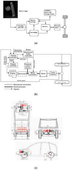
Figure 1.
(a) Hybrid Series configuration; (b) Simulated car model and (c) possible components arrangement.

Table 1.
Design specification and environment parameters.
3. Requirements of Performance
The model has as its main purpose to move within an urban context so it will be not required high standards of performance but a balance between maneuverability, agility, and driving features characteristics. In fact, despite the prevalent city use, our choices have to also guarantee the possibility to travel along extra-urban or motorway routes without any difficulty for the driver. The requirements are usually described by three parameters:
- Acceleration performance describes the time taken starting from zero speed to a certain high speed (from 0 to 100 km/h for example) on flat ground.
- The maximum speed is defined as the constant cruising speed that the vehicle can reach with full power plant load on a level road.
- Gradeability is defined as the grade (or grade angle) that the vehicle can overcome at a certain constant speed.
By analyzing the performance of commercial cars in the same category, the performance requirements illustrated in Table 2 were chosen.
Table 2.
Requirements of performance for the vehicle.
Further, we want to define, two other requisites (Table 3) mainly related to the reduction of air pollution in the cities. An adequate range in electric mode guarantees a reduced emission of pollutants for most daily journeys as well as a general improvement in fuel consumption.
Table 3.
Requirements of performance for the vehicle.
The Euro 6d standard is mandatory for the vehicles’ registration from 2021 onwards and imposes very low emission levels for the main pollutants.
4. Electric Motor
We now proceed to the choice and sizing of the main components that will be part of the final configuration starting from the electric motor. It is a critical part of a series of hybrid vehicles: it is the only component that supplies power to the wheels. The electric motor converts the electrical energy into mechanical energy to push the vehicle or, vice versa, to allow the regenerative braking and/or to generate electricity for recharging onboard energy storage systems.
Countless applications use its principles such as the industrial field, crafts, model building, traction, and much more. That is exactly why we can consider this technology mature and consolidated but, at the same time, the subject of numerous researches and studies aimed at improving performance and efficiency. The models used in the automotive field for hybrid and electric vehicles have more stringent characteristics than those used in the industrial sector. Generally, they have the following features [3,9]:
- high torque and power density;
- wide speed range;
- high efficiency over wide torque and speed ranges;
- wide operating capacity at constant power;
- high torque capacity on slopes;
- high overload capacity when overtaking;
- high reliability and robustness;
- low noise emissions;
- reasonable cost.
In hybrid vehicles, in addition to these, there must be integration with the thermal engine and an optimal voltage regulation during high-speed generation. Before sizing the component, we must analyze the various types of electric motor on the market to choose the most suitable one for our purposes. We briefly describe the four main categories of electrical machines used in the automotive sector: DC-machine, induction machine, permanent-magnet synchronous machine, and switched reluctance machine.
4.1. DC—Machinery
The DC motor is the oldest and most simple type of electric machine. A rectangular coil of rigid conductive wire mounted on an axis and free to rotate is immersed in a uniform magnetic field perpendicular to the rotation axis, generated by the poles of a magnet. When the coil is crossed by electric current, the action of the magnet produces a torque T expressed as:
where B is the magnetic flux density, I is the current intensity, L is the wire length and α is the angle between the coil plane and the magnetic field. For this operating principle, the presence of an organ that reverses the direction of current in the coil is necessary: commutators and brushes. These two elements are the cause of the major disadvantages in DC-motor. Brushes cause friction and radio frequency interference while commutators are responsible for torque ripples and limit the motor speed. Moreover, due to the continuous wear and tear, periodic maintenance of commutators and brushes is always required. In general, a DC-machine is inexpensive and simple to control but drawbacks, as seen previously, make it unreliable and mediocre in terms of performance.
4.2. Induction Machinery
An induction motor (or asynchronous motor) is an alternating current electric machine without mechanical switches and is widely used in the industrial sector. The operation of a three-phase asynchronous motor is based on the induction of a rotating field due to the superposition of the magnetic fields generated by a three-phase system of currents that run through the stator windings. A squirrel-cage rotor is the only typology used in the automotive field because it is self-starting, reliable and economical.
The control of induction machines is markedly more complex than that of DC-machines due to the nonlinearity of the dynamic model and so it needs a particular control strategy; the most employed is the field-oriented control (FOC). By using coordinate transformation, the model of induction machines is transformed from the stationary reference frame (α-β frame) to the general synchronously rotating frame (x-y frame). The x-axis is purposely selected to be coincident with the rotor flux linkage vector and the reference frame (d-q frame) becomes rotating synchronously with the rotor flux. Consequently, the torque T can be expressed in terms of the d-axis stator current components isd and the q-axis stator current component isq.
where p is the number of pole pairs, M is the mutual inductance per phase and Lr is the rotor inductance per phase. Thanks to the absence of mechanical commutators and brushes, the induction motor has high reliability and less noise and wear. It also has greater efficiency, energy, and specific power than the dc motor. The main disadvantage is the notable heat generation in the rotor due to the copper losses.
4.3. Permanent-Magnet Synchronous Machinery
Permanent magnet brushless machines represent an excellent alternative for hybrid and electric traction [10,11] and have been acquiring a large market share in the automotive sector in recent years. The presence of permanent magnets makes it possible not to generate a magnetic field in the rotor and therefore increase efficiency and power density. The most used is the permanent magnet synchronous motor (PMSM) which the stator and the rotor are both shaped like a cylindrical crown of laminated ferromagnetic material and separated by an air gap. In this case, the permanent magnets are located on the rotor. As with the induction motor, in the PMSM, the technique with FOC is the most appropriate and used. The correct operation of the motor is linked to the exact knowledge of the position of the flux of the permanent magnet and for this reason, it requires a position sensor which makes the control strategy more complex than IM. Using this strategy, it is possible to control the machine’s torque T by:
where p is the number of poles, ψm is the flux in the stator windings due to the presence of the magnets. Lq, Ld, iq, and id are, respectively, the inductances and currents in the stator windings in the q and d axes. The PMSM is characterized by very high efficiency and power density. On the other hand, the cost is greater than its competitors due in large part to the valuable materials of the magnets themselves.
4.4. Switched Reluctance Machinery
The switched reluctance motor is a valid candidate for use in electric and hybrid vehicles due to its construction simplicity [12]. Salient poles both on the rotor and on the stator characterize the machine; in the latter, the windings are concentrated, wound on each pole. The stator and the rotor are made up of a series of overlapping plates, which give rise to salient poles on their periphery facing the air gap. The number of poles in the fixed part is always greater than those in the mobile part; the most common configurations are 6/4 (6 stator and 4 rotor poles) or 8/6 (8 stator and 6 rotor poles). The torque in the SRM is produced by the tendency of the rotor to align with the exciting stator poles. The analytical expression can be expressed using the co-energy principle using the derivative of the inductance to the position of the rotor:
where i is the phase current, L the phase inductance, and θ the angular position of the rotor. The absence of permanent magnets or windings in the rotor reduces its complexity, size, and cost. The disadvantages, on the other hand, are related to the large oscillation between a minimum and maximum torque called torque ripple. This phenomenon produces chafing between poles and housings which lead to considerable acoustic emissions.
4.5. Design and Sizing
Referring to the characteristics shown in the previous points, we can make a direct comparison between the four types of electric cars, considering the most important aspects in the design of a hybrid vehicle [13,14,15]. The results can be entered in a summary table (Table 4) in which it was chosen to use a scale from 1 to 5 as a performance index, where 1 stands for poor and 5 for excellent.
Table 4.
Evaluation of existing machines for HEVs.
We can restrict the choice between the two categories with the highest score: induction motor and permanent magnet synchronous motor. The first is a mature and low-cost technology that has good average efficiency over a wide speed range making it ideal for a hybrid-series system. The synchronous permanent magnet machine, on the other hand, is a more expensive option but in addition to higher efficiency, it has two characteristics that are perfectly suitable for a city car: lightness and small footprint thanks to its excellent power density and very good performance at low speeds.
In this study, the requirement for high compactness and low weight is particularly important, considering the limited spaces of a city car, so the choice falls on the permanent magnet synchronous motor. Despite a higher cost, it guarantees the best performance on the market and at the same time very small dimensions. PMSM is a technology increasingly used in current hybrid and electric vehicles and this will consequently allow an improvement in terms of economic competitiveness. At the beginning of design, the rated power of the electric motor, which guarantees traction, can be estimated through the desired acceleration performance, in particular from the time taken to reach 100 km/h [3]. To do this, we need to know the vehicle’s speed Vb that maximizes both the drive torque and the engine power at the same time. In the first analysis, this speed can be obtained from the diagram in Figure 2, which relates the speed of the vehicle with the driving torque and the power of an electric motor common to a car of this category. Having a single transmission, we use the track c-d-e and we deduce that Vb = 48 km/h.
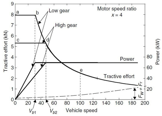
Figure 2.
Torque/power-speed characteristic of a commercial electric motor.
The following formula can be used to calculate the rated power Pn to satisfy acceleration performance:
where Mv is the total mass of the vehicle in kg, δ is the inertia factor, ta is the required acceleration time, Vf is the final speed (m/s), g is the acceleration of gravity (m/s2), fr is the rolling resistance coefficient, ρ is the air density (kg/m3), Cx is the drag coefficient e Sf is the front area of the vehicle (m2). The first term of the equation expresses the power used to accelerate the mass of the vehicle, the second and third represent the average power required to overcome the rolling resistance of the tires and the aerodynamic drag respectively. Using the vehicle specifications in Table 1, the acceleration time in Table 2 and of course setting Vf = 27.78 m/s (100 km/h):
Note that this nominal power value is only a starting point for our study. After choosing the electric motor and the other components, an appropriate verification of the fulfillment of all three performance requirements will be carried out.
4.6. Electric Motor Selection
Among the numerous alternatives available, the motor [16] was chosen, which meets the necessary power requirement. The rated power is 54 kW and, as expected, the engine is very efficient and compact but has a rather high cost. The machine data are shown in Table 5.
Table 5.
EM Datasheet.
5. The Micro Gas Turbine
The term “micro-gas turbine” (MGT) identifies a small power generation system (10 ÷ 100 kWel) based on a regenerative gas cycle which includes a compressor, a turbine, a recuperator, an alternator and an electrical interface for the transfer of power (Figure 3). Microturbines operate according to the thermodynamic cycle known as the Brayton cycle as well as the largest gas turbines. However, the thermodynamic cycle of a micro gas turbine is characterized by characteristic parameters rather low when compared with those of large plants. The radial single-stage compressor compresses the air up to the maximum pressure (with ratios of compression typically variable from 1 to 3). At the discharge of the compressor, the air, which raised its temperature during the compression, can be sent to the combustor directly or indirectly, after having through an exchanger that preheats the air using the heat from the turbine [17]. In the first case, a simple turbo gas cycle is carried out while in the second case there is a cycle regenerated which guarantees superior efficiency. The combustor then raises the gas temperature by sending the amount of fuel to the burner necessary to reach the maximum cycle temperature; subsequently, the hot gases expanded in the turbine stages. At the end expansion, gases, still with a temperature higher than atmospheric, can cross the recuperator before discharging the gas turbine. The gas-micro turbines on the market show significant differences in the layout and guarantee the best performance in the case of medium or high power (30 or 60 kW). However, all of them have characteristics in common, summarized in Table 6.
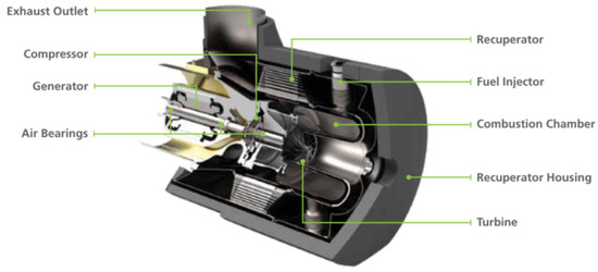
Figure 3.
Micro GT.
Table 6.
PROs and CONs of a micro-gas turbine.
The gas-micro turbines currently on the market are designed and sized mainly for the continuous production of electricity, support generation, or cogeneration. The main competitor, in this type of use, is certainly the internal combustion engine interfaced with an electric generator. Between the two systems, in static applications, the MGT certainly has better characteristics, as it has [18]:
- Better or comparable efficiency;
- Significantly reduced emissions;
- Less weight and bulk;
- Greater ease of installation;
- Less noise and vibrations;
- Significantly reduced maintenance;
- Possibility of using different fuels.
ICE engines have been the system for converting energy into vehicles for more than a century, while the use of MGT is still limited to prototypes and experiments. In this paper, we would understand whether the advantages of the microturbine in other fields of application can also be valid in the automotive sector, specifically in a hybrid configuration.
5.1. Design and Choice of MGT
The thermal engine, in a hybrid series car, has to design for satisfying the maximum power required for the propulsion of the vehicle in the most unfavorable situations, considering the performance of the electrical system too. The most demanding condition is to continuously guarantee the motion of the vehicle at high speed [3]; we can consider a highway route and choose a continuous speed value equal to 130 km/h (36.11 m/s). The nominal power required for the thermal engine, in our case an MGT, can be expressed as:
where V is the reference speed set at 130 km/h, ηt the efficiency of the transmission and ηm that of the electric motor. In the calculation, we assume a very pessimistic estimated value of the product ηt ηm equal to 0.7 and we consider the mass of the vehicle increased by 200 kg due to any passengers and baggage. In this way, the heat engine will be sized in the worst possible conditions. Referring to the data in Table 1, the nominal power of the MGT has to be:
Low power gas-micro turbines with encumbrance characteristics suitable for use on a vehicle are almost absent on the market, consequently, the selection, in this case, is very limited. Capstone Turbine Corporation is the only manufacturer capable of satisfying the needs requested and therefore C30 model was chosen [19] (in the comparison we also report the data of the C60, as it is the same size as the corresponding ICE). For this machinery, there are laboratory simulations that highlight the trend of efficiency and emissions as a function of load power. As previously stated, the best performance in terms of efficiency is achieved for values close to the maximum power while gradually decreasing as the load decreases [20]. The considered turbine is designed primarily for other applications than automotive and consequently, the model has elements superfluous for our purposes and inadequate dimensions. The product is sold with a metal protective case, a double base, and other accessories. The elements of interest in our simulation are those of the turbo gas group: compressor, combustor, turbine, and permanent magnet generator with rectifier. Therefore, an estimate of the size and weight of the component has to be made. The C30 model is also equipped with a high-quality recuperator that is not adequate in terms of both dimensions and cost. Considering that the recuperator constitutes almost 1/3 of the total cost of the micro-turbine, we have chosen to proceed with a preliminary project proposal for this component in the next paragraph. In conclusion, the data of Capstone C30 are shown in Table 7. The values of dimensions, weight and cost are obtained through estimates. MGT can operate with a wide range of fuels but compressed natural gas (CNG) was chosen for simulation due to lower emissions and lower costs
Table 7.
MGT specifications.
5.2. Recuperator Design
The recuperator is the component that allows a gas-micro turbine to match the internal combustion engine in terms of efficiency. We can define the main objectives of the preliminary plant [21]:
- High heat transfer efficiency (ε ≈ 0.9) and low-pressure drop (∆p/p = 5%).
- High operating temperature and pressure (T ≥ 700 °C and p ≥ 4 bar).
- At least 40,000 h of operation without significant maintenance.
- High surface-volume ratio (m2/m3 ≥ 1200) and low weight.
- Low installation cost obtainable through inexpensive construction materials.
Eventually, there are two main types of recuperator units used in the gas-micro turbines: primary-surface recuperators (PSR) and plate-fin recuperators (PFR) [22]. The volume/surface ratios of the two categories are comparable but the finned models present higher costs and reliability problems due above all to the poor management of thermal shocks by cause of the numerous welds. In this research, we will consider only the primary surface recuperators, which can be divided into three main configurations based on the arrangement of the surfaces:
- Cross corrugated (CC) is widely used in industry, built by simple molding processes, and then welded to the edges. Very important in sizing is the ratio between pitch and height of the single channel.
- Corrugated undulated (CU) is constructively very similar to the previous one but with slightly higher costs. The height of the channel must be selected in such a way that the two countercurrent fluids can cross the same surface thus optimizing the heat exchange.
- Crossway (CW) is unlike the two previous types has a rectangular or trapezoidal channel shape; the molding process is difficult to implement and in general, for CW the bending method is used. Moreover, in this case, the geometry of the sections is very important.
We will now make use of the results of experiments and simulations [21] that compare the three types of recuperators to choose the one that best suits our purpose. From these studies, we can deduce that the CW model is the one with the best characteristics both from compactness and efficiency in heat exchange, even if with slightly higher costs. We will opt for this type of component as it combines in the best possible way adequate performance and compact dimensions. We now proceed to the choice of the material of the recuperator in question, taking into account that, for this category, the cost of raw materials corresponds to about half of the total cost. Fe-25Cr-35Ni steel was chosen because it is quite inexpensive and capable of operating up to 750–800 °C and resisting corrosion and oxidation phenomena that quickly reduce the life cycle of the component. The even cheaper 347 stainless steel cannot guarantee the same performance [23].
The dimensions and weight are now determined by a rough estimate using data sheets of larger size recuperators and the characteristic of CW model. The lack of complete data concerning the temperatures and operating pressures of the micro-turbine does not make detailed design possible. The element will be 350 mm high, 200 mm wide and 120 mm thick. Once the final volume is computed, the density of Fe-25Cr-35Ni steel and estimating that the metal occupies about one third of the total volume, we can obtain the weight of the recuperator through the simple relationship:
The weight has also been increased by a factor of 1.3 for additional safety. To estimate the cost, remember that the raw material affects about half of the total cost. The price per kg Pu for Fe-25Cr-35Ni steel is 13 €/kg and always considering a safety factor 1.3 we can define the total cost as:
The efficiency and pressure drop are determined approximately based on the average values of the CW category, with the first is equal to 90% while the second is equal to 4%. The overall data of the recuperator model are summarized in Table 8.
Table 8.
Recuperator datasheet.
6. Battery Pack
One of the basic points in a hybrid vehicle is the energy storage system. The fundamental component is certainly the storage of the electricity produced by the thermal engine (MGT) or by the electric motor during regenerative braking. The energy thus stored can then be supplied at the appropriate time during the driving cycle. There are various methods for storing energy in a vehicle, but we will consider only the electrochemical battery, a device that converts chemical energy into electrical energy and vice versa through oxidation-reduction reactions. It is a versatile, relatively inexpensive, and mature system since it has been used for decades. In the future, super-capacitors and the electric flywheel appear interesting, alongside the electrochemical battery. First, we need to determine which type of battery to use. We will consider only the two models currently present in vehicles in circulation: Nickel-metal hydride batteries and lithium-ion batteries. Older types such as lead-acid or nickel-cadmium batteries have significantly lower performance indices as well as being toxic and dangerous for human health. Other models such as sodium nickel chloride (ZEBRA) or lithium polymer batteries are still being tested and will be a valid alternative for the future.
6.1. Nickel-Metal Hydride Battery
The nickel-metal hydride (NiMH) battery has been on the market only since 1992 with characteristics similar to those of nickel-cadmium. The main difference is the use of hydrogen absorbed in a metal hydride instead of cadmium in the cathode. When the battery is discharging, the metal hydride in the negative electrode is oxidized to form a metal alloy and the nickel oxide hydroxide in the positive electrode is reduced to nickel hydroxide; During the charging phase, the reverse reaction occurs. The electrolyte is always a basic paste of potassium hydroxide while the potential difference at the poles is 1.4 V. The nickel-metal hydride accumulator guarantees a good energy density (up to 100 Wh/Kg) and an excellent power density (up to 300 W/Kg), clearly superior to other nickel-based batteries. The useful life span is very good (more than 1500 cycles), it can recharge quickly and does not present toxicity or carcinogenicity problems like its cadmium counterpart. Due to its best characteristics and the absence of elements harmful to human health and the environment, Ni-MH batteries have almost completely replaced Ni-Cd in the transport sector. The disadvantages consist of a fairly high cost, a good efficiency but lower than almost all the other types and a high self-discharge rate [24]. To date, Ni-MH batteries are used in many hybrid and electric cars, thus covering a large portion of the current market.
6.2. Lithium-Ion Battery
The lithium-ion battery (Li-Ion) is today the most widespread technology in the field of energy accumulators, used in almost all applications and especially in the consumer electronics sector (smartphone, notebook, etc.). The anode is made up of lithium atoms immersed in graphite layers, the cathode is a lithium salt (usually LiMn2O4) and the electrolyte is a lithium perchlorate solution (LiClO4) in ethylene carbonate (C2H4CO3), an organic solvent. The open-circuit voltage that develops in the reaction is 3.7 V. Alternatively, nickel or cobalt salts can be used in the anode but in general, manganese-based salts are almost always preferred as they represent an adequate compromise between performance and cost of materials. Lithium has two fundamental characteristics: it is the lightest metal ever and the one with the highest standard reduction potential. The first guarantees excellent energy density (up to 200 Wh/Kg) and good power density while the second allows high voltage in the cell (3.7 V). The efficiency is also among the highest in absolute comparable only with ZEBRA batteries and the self-discharge rate is rather low. However, the lithium-ion battery still has a high cost, improvable life cycle, and lack of safety in the case of damage to the housing and disposal problems. The enormous impact that this system has had in the last 30 years has allowed an excellent technological maturity: it is the subject of continuous studies and research that have allowed a constant and progressive improvement in performance and safety in parallel with a slight decrease in costs. As for the electric or hybrid traction sector, the Li-Ion battery is increasingly used thanks to its excellent performance and its enormous diffusion.
6.3. Battery Package Selection
Similarly to what has been done for the electric motor, we now compare the two models in the fundamental aspects in choosing a battery [25,26,27,28] by assigning a score from 1 to 5 (Table 9). The vehicle we consider is a small car mainly for city use which must guarantee good autonomy and good performance even outside the urban environment. The most important objectives therefore that the battery pack must guarantee are a reduced size, a not excessive weight together with a good capacity and energy density.
Table 9.
Evaluation of NI-MH and Li-Ion batteries.
A quick analysis clearly shows that the lithium-ion battery is the one that comes closest to the set purpose considering the density of power and energy of particular relevance. The presence of numerous studies regarding the optimization and management of the battery as well as a wide selection of models that allow satisfying even very specific needs also contribute to the choice. We conclude therefore the configuration will have as its energy storage system a lithium-ion battery pack.
6.4. Battery Package Design
The size of the battery package is closely related to the desired range in electric mode Aem (in an urban cycle) which in our case corresponds to 20 km, a value that allows the vehicle to emit zero emissions for most of the daily routes. Preliminarily it is necessary to formulate a hypothesis on the consumption of electric energy per kilometer Ce (kWh/km) of the car; by analyzing real data on hybrid vehicles of similar size and power we can consider an average consumption of 0.13 kWh/km. To extend the battery’s life, an interval of the state of charge RSOC in which the battery will operate has to be defined; we choose RSOC = 30%, even more, conservative value than that recommended by the cell manufacturers. We can now obtain the energy Ebatt necessary to fully cover the 20 km of expected autonomy.
We then set a nominal voltage Vv inside the car of 220 V; this represents a compromise between passenger safety, peak power, and cell size. The voltage of a lithium-ion element Vl is equal to 3.7 V, the number of necessary elements Ne is determined by:
From here, we calculate the capacity Cbatt required for the battery pack considered:
We will choose from the producers a cell of a size close to and greater than the capacity value obtained. In this case, it corresponds to 40 Ah and the total energy will consequently be 8.88 kWh. The datasheet of the cell and the entire module, consisting of 60 elements connected in series, is shown in Table 10. For the total weight of the entire battery pack, an increase due to packages and any accessories was considered.
Table 10.
Series Battery Modules specifications.
7. Other Components
In addition to the components analyzed above, other elements affect the performance and cost of the car: DC/DC converter, inverter, and fuel tank.
7.1. DC/DC Converter
DC/DC converter is an electrical coupling device that converts a source of direct current from one voltage level to another [3]. This component allows you to change the value of the voltage output from the generator or the battery to have the same value in correspondence with the dc bus. The absence of this element (directly connected system) would be highly limited in the choice of the generator and the accumulator as they should have the same rated output voltage. The DC/DC converter can be placed in two different positions in the drivetrain: between the generator and the DC bus or between the latter and the battery. The best solution is certainly the second one since the voltage of the DC bus can be determined by varying the rotation speed of the primary motor, voltage variations of the battery pack do not affect the DC bus and the energy of accumulator can be used. In hybrid and electric vehicles, the DC/DC converter has to be bidirectional and buck-boost type to guarantee high efficiency in regenerative braking. The data of the model chosen are shown in Table 11.
Table 11.
Datasheet of DC/DC converter.
7.2. Inverter
The previously proposed electric traction motor works in alternating current and therefore it is necessary to convert the direct current coming from the DC bus into alternating through a device called an inverter. To make it possible to recover the braking energy, a component, called a rectifier, has to be present to carry out the reverse process, i.e., the conversion of alternating current into direct current. In the vast majority of electric or hybrid vehicles, inverter and rectifier are present in a single device, the inverter-rectifier group, capable of operating in a bidirectional way. In technical jargon, the whole group is referred to simply by the name of the inverter. The inverter contains some of the most critical components of the electric vehicle that have a direct impact on the motor drive. The presence of numerous electronic components in the device such as MOSFET or IGBT is subject to failures that harm the control and operation of the engine itself. Therefore, adequate parameters of integrated protection and continuous monitoring are required.
The datasheet is shown in Table 12.
Table 12.
Inverter Datasheet.
7.3. Fuel Tank
The Capstone C30 micro-turbine allows the use of different fuels in both liquid and gaseous form and the choice of one of them for subsequent simulations has to be made based on the final objectives of the car. The fundamental issue is pollutant emissions that favors the choice towards a fuel in gaseous form, specifically compressed natural gas (CNG), and often called simply methane. The latter in fact can guarantee, compared to diesel, significantly lower emission levels, especially of NOx and particulates, particularly important in urban areas; the cost of fuel is also lower than that of its counterparts in liquid form.
For the choice of the fuel tank from the catalog, the fundamental requirement remains that of minimizing the overall dimensions and costs and, at the same time, guaranteeing safety and fuel capacity. The data are shown in Table 13.
Table 13.
Fuel tank specifications.
8. Vehicle Evaluation
From the driver’s point of view, a very important aspect of a car is performance. As previously stated, the hybrid vehicle studied, in addition to ensuring low consumption and polluting emissions, has to be able to ensure satisfactory levels of performance for the end-user.
We now proceed with the verification using Advisor software, which uses the MatLab environment to simulate the performance of a properly configured vehicle. Within the program, it is also possible to carry out an acceleration and gradeability test. Vehicle input data naturally correspond to those shown in Table 1 and to each component dimensioned hitherto. Recall that the performance requirements were defined in Table 2. The simulation results are shown in Table 14. The results show that the vehicle falls within the required acceptability range but, as expected, does not have any particularly interesting characteristics. The achievement of better performance can be obtained through the use of a larger MGT, but the high costs and its dimensions do not make it possible to implement this strategy.
Table 14.
Vehicles Requirements.
9. Driving Cycle
To be able to homologate a vehicle, car manufacturers are required to carry out tests on driving cycles prescribed by the legislation in which the levels of performance and emissions of pollutants are determined. From 1970 to 2017 the European reference was the NEDC cycle (New European Driving Cycle); the cycle is considered unrepresentative of a real driving route due to the mild accelerations and repetitiveness of the speed profile. Since 2017, the NEDC cycle has been replaced with the WLTC (Worldwide harmonized Light vehicles Test Cycles) which is part of the largest test procedure for light vehicles worldwide (WLTP). Unlike the NEDC, this cycle is formulated based on a real average guide and is divided into four sections with different average speeds. In our simulation, however, we will use a different approach than that of the official approval standards. The configured car is designed for purely urban use with sporadic extra-urban journeys while the new WLTC cycle temporally divides the total route into 52% urban driving and 48% extra-urban considering therefore an equally distributed division of the two modes. Our study will instead consider a 75/25 distribution in favor of the city path by adopting two different cycles:
- WVUCITY urban cycle repeated 10 times to simulate the experience of a typical city trip.
- Extra-urban cycle designed by us through MatLab for the motorway section and high-speed roads (repeated twice).
Our goal is to represent a pre-eminent city use such as the journey from home to work combined with some longer routes but which occur more rarely as a trip out of town on the weekend, where highway routes are also addressed.
9.1. WVUCITY Urban Cycle
The WVUCITY cycle corresponds to the urban section of the wider FTP-75 driving cycle (Federal Test Procedure) used mainly in the United States. It represents a pure city route consisting of numerous stops and restarts that simulate traffic conditions and the presence of traffic lights, very similar to the low-speed section of the WLTC. The speed profile is illustrated in Figure 4 wherein green the slope is represented which in this cycle is always equal to zero while the kinematic characteristics are shown in Table 15.
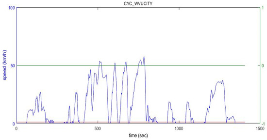
Figure 4.
Speed profile of WVUCITY cycle.
Table 15.
WVUCITY cycle.
9.2. Extra-Urban Cycle
The Advisor software allows you to create a personalized driving cycle through Matlab therefore we wanted to use this function to design an extra-urban route based on our particular needs. The goal is to simulate a journey that included about 30 min on the motorway and 15 min on fast-moving roads to represent an occasional journey (about once a week). In Figure 5 we can observe the chosen speed profile (blue line) and slope profile (green line). Finally, in the Table 16, there are characteristics of the cycle.
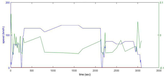
Figure 5.
Speed profile (blue) and slope profile (green) extra-urban cycle.
Table 16.
Extra Urban Cycle.
10. Simulations
After successfully checking the adequacy of the weight distribution and vehicle performance and choosing the driving cycles, the simulation is now carried out using the advanced vehicle simulator (Advisor) software.
The program exploits the Matlab/Simulink environment for the definition, management, and control of any type of vehicle, from conventional ones up to electric, hybrid and fuel cell vehicles. Advisor is modular software, therefore it allows easy modification of the input data that correspond to the characteristics of the vehicle and its components together with the environmental and aerodynamic conditions; the simulation part then takes place in an almost static mode, that is, by setting constant values instant by instant during the driving cycle, chosen from the numerous alternatives in the database. Finally, in output, we will have the energy trends, the fuel consumption, the performance of the vehicle, or its component defined for each point of the chosen driving cycle.
The logics tested was the On-Off and the next step will be considered the possibility to adopt a load following logic. As preliminary attempt, we considered the On-Off logic satisfactory. Further development, already planned in the optimization of the vehicle, will be to implement a real-time strategy or a global optimization, that we believe will bring better results. Let’s proceed with the simulation of the vehicle first in the urban cycle (10 WVUCITY) then the extra-urban one (two cycles). By separating the two cycles, it is thus possible to observe the variation of some significant parameters in the different driving conditions. In each simulation, we will focus on six output parameters:
- MGT consumption in terms of fuel (L/100 km);
- MGT consumption in terms of energy (kWh/km);
- SOC history time;
- range in an electric mode of the vehicle for the urban cycle;
- time interval in which the MGT works;
- distribution of energy in the components.
10.1. Simulation in Urban Cycle
The first step to follow in the simulation is the configuration of the characteristic parameters of the vehicle on the software as previously done in the performance check and shown in the figure; for each component, Advisor allows a very detailed setting both from the dimensional point of view and in the choice of the characteristic parameters to fully define each element of the vehicle. Since the gas-micro turbine is not present in the database, an internal combustion engine has been appropriately configured with the data and characteristics of the MGT. The type of fuel, which in our case is CNG, is determined by varying the density values and the lower heating value (LHV) in the specific section. After carrying out the test, we highlight as a first aspect the temporal trend of the SOC related to the operating intervals of the MGT, in Figure 6.
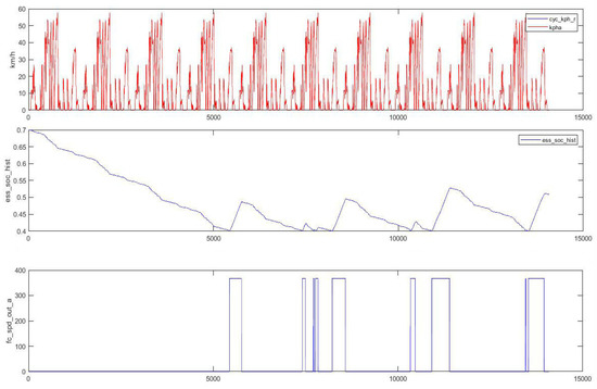
Figure 6.
Speed profile (up) (km/h), SOC history (center) and time interval in which the MGT operates in ON-OFF logic (down) in the urban cycle.
It is immediately evident how the MGT works in limited time intervals thanks to the large autonomy guaranteed by the battery. These trends were obtained after numerous tests in which the parameters relating to the control strategy were varied until obtaining the best results in terms of autonomy and consumption. The system follows a logic with thermostatic control except for some points, which correspond to power peaks, in which MGT switches on to assist the electric traction motor and guarantee adequate performance. In none of the cases has it been possible to avoid the three short starts and turns off around 7500 s due to the software settings that do not allow configurations to avoid this phenomenon, which in turn implies an increase in average consumption. From the graph obtained, it is also possible to obtain the range in electric mode (Aem) considering the time required for the battery charge state to pass from the maximum value (0.7) to the minimum value (0.4). It corresponds to about 5500 s which, at an average speed of 13.59 km/h, is equivalent to:
The estimated value of the specific consumption regarding the battery sizing was therefore in line with the actual value since the expected range (20 km) is very similar to that obtained by simulation. The level of autonomy in the urban cycle is very satisfactory, considering also the conservative interval considered for the state of charge of the accumulator.
During the driving cycles. The values obtained are shown in Figure 7. The figure shows the energy values in kJ at the inlet and outlet of each component with the related efficiencies. On the right, there are also the data relating to the regenerative braking phase, significant in an urban cycle, which allows the recovery of a percentage of energy that would otherwise be lost. We want to focus, in particular, on the most innovative aspect of the study, namely the MGT. As we can see from the graph, the average efficiency is equal to 29%, a very good result if we consider the presence of transients that lower the average value. MGT operates close to the optimal point and it is one of the strengths of the series hybrid configuration. Fuel consumption sfc for the urban cycle is equal to:
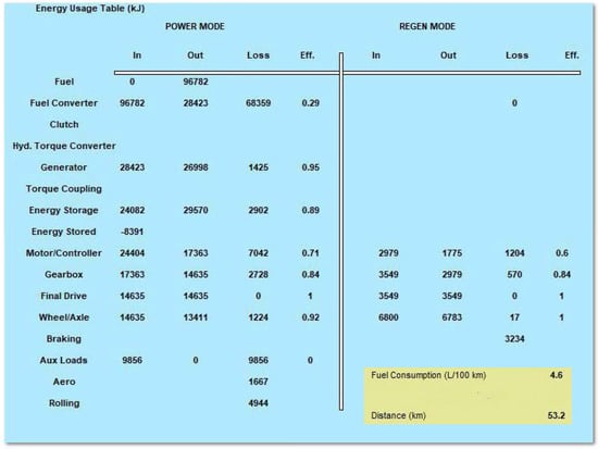
Figure 7.
Energy profile and fuel consumption for the urban cycle.
For the specific consumption of the microturbine in terms of energy, it is possible to refer to the commercial device and use the input value of the component, that is the total energy from the initial instant to the final instant (Etot), which in this case corresponds to:
If we divide this value by the kilometers traveled (dmiss,u) we obtain the specific consumption sfc, which for the urban cycle considered is equal to:
In Table 17, the results obtained in the simulation in the urban cycle are shown.
Table 17.
WVUCITY cycle results.
We can conclude that the proposed vehicle has shown excellent autonomy in electric-only despite the restrictions on the state of charge of the accumulator, an average efficiency for the MGT close to the maximum value and good fuel and specific consumption. The latter two can be improved through a control aimed at eliminating small defects regarding the switching on/off of the MGT.
10.2. Simulation in Extra-Urban Cycle
The same procedure has been used for the extra-urban cycle. We configure the system exactly as in the previous case and simulate the software. Similarly to the urban cycle, the first aspect to observe is the SOC trend during the course and the time interval in which the micro turbine is operating (Figure 8). It is evident from a first glance at how the trend of the battery’s state of charge is different from the urban cycle. The decrease is very gradual since at high speeds it is the MGT that will supply power to the electric motor most of the time as seen in the graph below the figure. SOC takes all 169 km of the route to go from the maximum value to the minimum value. We now proceed to the analysis of energy and consumption (Figure 9) and check whether they are satisfactory even in the extra-urban cycle. It can be observed how this type of route leads to a different distribution of energy exchanges starting from the lesser importance of regenerative braking. By always focusing on the microturbine, there is a slightly lower average efficiency compared to the urban cycle but still very good if we consider that at high speeds this component is more stressed. In this case, MGT assists the electric motor for a longer time, especially in the motorway sections. The fuel consumption is excellent since the microturbine can work continuously for long distances and even the unwanted transients are irrelevant in the total distance traveled. Also, for the specific consumption in terms of energy, we proceed in the same way as we did for the urban cycle. The value obtained for the total energy input to the MGT for the entire cycle corresponds to:
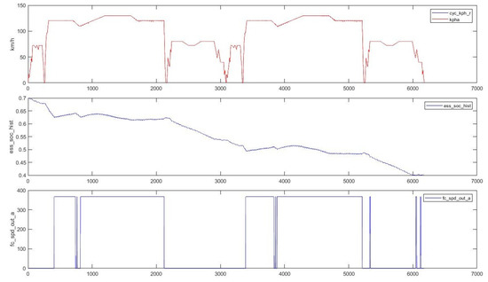
Figure 8.
Speed profile (up), SOC history (center) and time interval in which the MGT works (down) in the extra-urban cycle.
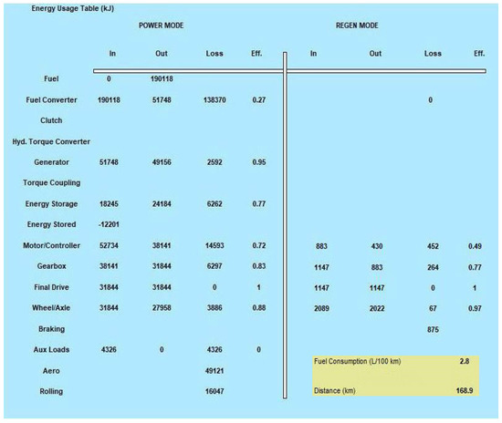
Figure 9.
Energy results and fuel consumption for the extra-urban cycle.
Dividing once again by the total of the km covered in the two cycles (dmiss,e) we obtain the corresponding specific consumption value:
In this case, the specific consumption is lower than in the urban cycle, achieving excellent results. In Table 18 there is a summary of the data highlighted in this simulation.
Table 18.
Extra-urban cycle results.
In conclusion, we can consider excellent performance in the extra-urban cycle designed by us, in which we also ascertained the accuracy in the MGT design. The requirement that the latter was able to adequately support the electric motor at high speeds was fully satisfied.
To obtain the results in terms of consumption for a combined cycle, it was decided to use a weighted average between urban (75%) and extra-urban (25%).
11. Comparison with an Actual Hybrid Vehicle
To better judge the performance and consumption results obtained in the previous simulations, a comparison should be made with a car on the market with similar characteristics. The Hybrid Vehicle, here considered, is a 2015 version that represents a good option by being in size and weight almost identical to the vehicle being studied and comparable overall power, even if distributed differently. Some technical details of the model [25] are summarized in Table 19. Although it is two different configurations, since the purpose of the work described here is to propose a commercial and competitive solution, we found it useful to compare it with the best-selling model, currently, of hybrid vehicle. Finally, we will also compare with two other types of hybrid machines, this time in the “series” configuration. We added this just for future comparison, because both the engine and the battery pack are very different.
Table 19.
Hybrid Vehicle characteristics.
An interesting aspect is the possibility of comparing two cars with a completely different approach to hybrid mobility starting from the series-parallel configuration (HSD system). Another substantial difference is that in the case of the considered commercial vehicle, the internal combustion engine (Atkinson cycle) is dominant compared to the electric one unlike what happens in our case. Even the battery pack is based on a remarkably different view through a Ni-MH battery with less power, capacity, and size but for which we expect less autonomy. The transmission is also of the continuously variable type of the proprietary type called E-CVT in which the management by the electronic control unit takes into account the type of route, the driving modes (power request by the driver) and the state of charge battery. The lack of detailed data, in particular on the control strategy, prevents us from simulating the model through Advisor and subjecting it to the same driving cycles in a reliable manner; we will rely upon on-road tests from authoritative journals in the sector or scientific research. The parameters with which the comparison is possible are the performances in terms of acceleration and speed, consumption on a mixed cycle, autonomy in electric-only, emissions and costs. The last two points will be examined later in the next chapters in detail. For the detection of performance, we relied on the road test [26], which are shown in Table 20. Where available, the deviations with the values declared by the manufacturer are also highlighted.
Table 20.
Commercial HV performance.
It should be noted that the measured values of acceleration and of the time required to travel 1 km are substantially identical to those of the car examined. The maximum speed of the Toyota Yaris Hybrid is approximately 10 km/h higher due to the greater power of the thermal engine compared to the Capstone C30. Overall, in the first analysis, we can consider the main performance indices between the two models comparable. For the data on fuel consumption (Table 21), Russian–Bulgarian research from 2018 was taken into account in which this HV is tested on the road along routes of numerous types and with consumption detection through control devices that record values every minute [27]. The urban routes were also repeated both in normal and in energy-saving mode (ECO mode), which optimizes fuel consumption at the expense of performance. All research data will be reduced by 5% due to the presence of two additional passengers (on average consumption increases by 0.5% for every 20 kg of additional load). In Table 22 the final average results are reported for 3 urban and 7 extra-urban cycles, 2 of which are motorway; the value of consumption in the combined cycle is calculated using a weighted average (75% urban, 25% extra-urban) in a similar way to what was done on car object of the report. Considering that the road tests are certainly more demanding than a software simulation, we can still define the consumption of the commercial HV higher than the vehicle we configured. The activation of the ECO mode brings significant savings in terms of fuel, however at the expense of the performance, so much so that the studio has decided not to use this mode in the extra-urban route. For the range in electric mode, the manufacturer has not declared any official value, but the numerous road tests carried out by European magazines in the sector agree that, in the most optimistic case, the car performs in electric modality only 4 km, and in the most demanding routes the value is around 2–3 km. This is a predictable result due to the battery model with which the car is equipped, with reduced capacity and power, especially if compared to the overall power of the vehicle. The comparison between our proposed vehicle and the commercial one is presented in Table 22.
Table 21.
Fuel consumption for considered HV.
Table 22.
Comparison between vehicle and HV.
Overall, we can say that the vehicle understudy has comparable or even better indices than a model on the market that is generally highly appreciated by end-users in its category.
In addition, a comparison was made with commercial series hybrid vehicles, such as the I3 and Volt.
- (a)
- BMW I3 Range Extender ©
The BMW I3 Range extender version is a series hybrid vehicle on the market until 2019. It is a model where the electrical part of the powertrain is clearly dominant with a 125 kw electric motor assisted by a small internal combustion engine of only 647 cc that intervenes only in the case in which the SOC of the battery drops below 7%. The battery pack has a high capacity (94 Ah) to obtain a large range in electricity mode and strongly limit fuel consumption. The list price of the car is around € 40,000. Table 23 summarizes the technical specifications of the aforementioned vehicle.
Table 23.
BMW I3 main data.
To summarize the performance (Table 24), fuel consumption and range in electric mode (Table 25) we follow the values provided by the manufacturer. The second are evaluated following the NEDC while the latter following the WLTC. Considering the vehicle range in electric mode, the road tests have shown that the actual value is considerably lower.
Table 24.
BMW I3 performance characteristics.
Table 25.
BMW I3 fuel consumption.
- (b)
- Chevrolet Volt ©
Chevrolet Volt is a series hybrid car produced by General Motors under the Chevrolet brand and is marketed in Europe under the name Opel Ampera. In addition, this model presents a prevalence of the electric part, but much less pronounced than the BMW I3. In fact, it is equipped with two electric motors respectively one 111 kW and one 64 kW auxiliary which intervenes at high speeds, and with a rated 75 kW internal combustion engine. The lithium-ion battery is smaller than that of BMW with 18.4 kWh of maximum available energy. The ICE intervenes only when the charge of the battery pack drops below 30%. The list price is around € 40,000. The data sheet of the model is shown in Table 26.
Table 26.
Chevrolet Volt main data.
Table 27 reports the vehicle performances, while the fuel consumption and range in electric mode are shown in the Table 28. For consumption, a combined cycle consisting of a motorway component and a town is considered.
Table 27.
Chevrolet Volt performance characteristics.
Table 28.
Chevrolet Volt fuel consumption.
Finally, Table 29 shows the comparison of the various solutions.
Table 29.
Vehicles comparison.
12. Polluting Emission
Environmental issues are nowadays the focus of attention in numerous political debates, demonstrations and more generally in world public opinion. The society is increasingly interested in this type of problem, manifesting the need to contain the progressive deterioration process that has sharply accelerated in recent decades. Pollution is defined as the alteration and modification of the natural balance due to substances, devices, materials, or machines used by man. Our interest naturally focuses on the pollution caused by the circulation of endothermic engine vehicles, which in urban areas contribute up to 70% of total emissions. The transformation of fuel into thermal energy and mechanical energy is the cause of energy losses and the emission of pollutants. Regarding the latter, they are mainly represented by some substances:
- Nitrogen oxides(NOx)
- Carbon monoxide (CO)
- Particulate (PM)
- Unburned hydrocarbons (HC)
Currently the presence of sulfur oxides (SOx), due to the presence of sulfur as an impurity in fuels, is much less significant than in the past. Carbon dioxide (CO2), on the other hand, does not cause significant problems for human health but is very dangerous for the Earth’s ecological system as it contributes significantly to the so-called “greenhouse effect”. To limit the emissions of pollutants, the European Union has set a series of limitations imposed on the emissions of vehicles sold by the member states. The first layout took place in 1993 with the introduction of the EURO 1 standard up to the most recent EURO 6 in 2014 (updated in the EURO 6d version in 2020). In Table 30, the limit values of the polluting compounds imposed by the EURO 6 regulation are detailed.
Table 30.
EURO 6 directive.
Our goal now is to compare the emissions of the MGT with those of the HV selected and to observe whether they fall within the stringent parameters imposed by the European provisions.
The commercial one has been approved with the old NEDC and therefore also the declared emission values refer to this cycle; for the correctness and a reliable comparison we will also use specific consumption values (kWh/km) referring to the NEDC for the proposed vehicle. A simulation with the Advisor software of the cycle repeated four times was chosen so that the use of MGT is significant. The specific consumption obtained is:
The MGT number of pollutants in g/kWh is known and can be easily converted into g/km through the specific consumption just obtained. Table 31 shows the nameplate values for the main compounds and the corresponding in g/km in the NEDC cycle for the MGT considered.
Table 31.
Polluting emission of selected MGT.
Now, we will compare the values obtained with those declared by the manufacturer and reserchers and the limit values imposed on the homologation cycle by the EURO 6 standard (Table 32).
Table 32.
Comparison of polluting emission.
If there are no problems of any kind for both particulates and carbon monoxide, the proposed vehicle has values higher than the HV for NOx and HC, but still lower than the limits imposed by law.
This is mainly due to the absence of systems capable of limiting the production of pollutants, included in most cars, such as the exhaust gas recirculation (EGR) system or the catalytic converter. The first allows the elimination of a good percentage of NOx while the second guarantees very low levels of unburned hydrocarbons. The use of an EGR system and a catalytic converter allows the microturbine to fully comply with the stringent requirements imposed by today’s European regulations, giving rise to values that are comparable or almost comparable with those of modern internal combustion engines, specifically designed for the optimization of consumption and the limitation of pollutant emissions.
13. Cost Analysis
After successfully checking the performance, consumption and emissions for the vehicle studied about a car on the market, it is now necessary to examine whether the car is equally competitive in economic terms. A rough study will be carried out on the main cost items, always making a comparison with the commercial HV one. For a vehicle, the life cycle cost (LCC) is the sum of the acquisition cost (AC), the operating cost (OC), and the maintenance cost (MC) [28,29].
To undertake this analysis, it is necessary to highlight that the cost of an asset does not remain unchanged over time. In economics, the present value (PV) is that of determining cash flow. Generally, it is lower than the future value (FV) since the currency has the potential to earn, that is, it can generate income if properly invested. The rate at which current and future money can be exchanged is determined by the current interest rate r. We can define the present value accordingly through the following expression:
with i period in which the difference between the two values is evaluated. Considering a useful life cycle for the n-year vehicle, the cumulative present value (CPV) will be:
In our analysis, we will consider a useful life of 10 years and a current interest rate r equal to 5%. This will affect the operating and maintenance cost but not the acquisition cost as it occurs at zero time.
13.1. Purchasing Cost
Defining the precise value of the purchase cost for the previously configured vehicle is not feasible in this pre-prototyping phase as the lack of detailed data on the construction aspects, materials and minor components does not allow a precise economic analysis. However, we can estimate the cost starting from that of the main components in the previous chapters, using statistical averages for vehicles of the same category and taking advantage of studies that correlate the costs of the material, minor components, processes and distribution based on the size of the car and power. In Table 33 the costs of each element of the system are shown. Expenditure for distribution was set at 7% of the total manufacturing cost while the margin of retailers at each level of the supply chain was 15%.
Table 33.
Allocation cost.
The estimated acquisition cost for the proposed vehicle is:
For the acquisition cost of the commercial HV here considered, the average list price in 2020 was considered excluding promotions, discounts, and bonuses. The value obtained is:
13.2. Operating Cost
Operating costs include energy expenditure (Cen) understood as the sum of the cost of fuel and electricity, the tax for the ownership of the vehicle commonly known as the car tax (Ctax) and the insurance policy (Cins). Some parameters and costs must first be defined to be able to calculate the operating costs (Table 34). For the costs per liter of CNG and petrol, reference was made to the average prices for Italy in 2020 while the charging of the battery from the outside is always taken as domestic charging. Let us now calculate the annual cost of energy first for the proposed vehicle () and then for the HV () by taking the consumption values sfc in l/km previously obtained for the combined cycle. The battery of our configuration will be recharged every time by 30% of the maximum available energy value (Ebatt) as it is assumed to be operational in the simulation only for 0.4 ≤ SOC ≤ 0.7. For the commercial vehicle HV, we have assumed a 50% recharge.
Table 34.
Calculation parameters for operating cost.
For our proposed vehicle:
As expected, the much lower cost of CNG compared to gasoline significantly influences the annual energy costs resulting in a 57% lower expense in favor of the vehicle being studied. The cost of insurance varies according to the annual distance, car characteristics and type of power supply. The first two points are the same for the two models while the third involves a greater expense for the natural gas car. Assuming Italian average values for cars in the category and with 15,000 km of annual travel, we have values equal to:
The car tax on a hybrid vehicle is strictly dependent on the total maximum power, calculated as the algebraic sum of the power of the thermal engine and electric motor, and the European standard with which the car was registered. For the EURO 6 category, the average Italian stamp duty in 2020 amounts to 3.20 per kW. Considering the two models, we can calculate:
The annual operating cost OCi will therefore simply be the sum of the three previous items:
Over the entire 10-year life cycle, using the present value method, total operating costs amount to:
13.3. Maintenance Cost
The costs due to planned and extraordinary maintenance are an important part of users’ annual expenditure. For the HV, the cost of planned maintenance can be easily calculated thanks to the transparency policy of the manufacturer who reveals in advance the prices of the annual service for each car model. We will consider the average price of service to which we will add that of the mandatory periodic inspection (MOTtest). The cost of the planned annual maintenance (MCp) for the Toyota Yaris Hybrid is therefore equal to the sum of the average cost of service (Cserv) and the average cost for inspection (Cinsp).
In addition to the ordinary interventions, the unforeseen replacement of worn components, faults and repairs have to be taken into consideration. These take the name of extraordinary maintenance which, having a stochastic nature, it is not possible to quantify exactly but only through estimates. We will also consider the replacement of tires, whose life cycle also depends on factors independent of the distance traveled, such as the driving style of the driver. As a first approximation, we can put an estimate of the annual extraordinary maintenance (MCe) for the commercial vehicle equal to 80% of the planned one.
The total annual amount for maintenance is simply the sum of the two previously calculated items:
The maintenance costs relating to the proposed MGT vehicle proposed are, at this step of design, impossible to calculate in detail but can be estimated taking into account the HV ones. The car studied is fueled by natural gas, which entails an increase in ordinary expenses as more rigid and expensive controls are provided, however, the presence of MGT, less subject to breakdowns than an internal combustion engine, decreases extraordinary expenses. Considering the other aspects comparable, at least as a first approximation, we can set the total maintenance costs equal for the two models considered.
The overall cost of maintenance in 10 years is the same for the two cars and is equal to:
13.4. Life Cycle Cost
The life cycle cost will simply be the sum of the acquisition, operating and maintenance cost. Let’s now define the total costs for the proposed vehicle and the hybrid vehicle as:
As can be seen after 10 years the total costs of the simulated model are lower than those of the existing model and this is due to the lower operating costs, which in turn depend heavily on the difference in price between the unit cost of the two fuels. We can say that CNG power supply has been a winning choice to save over the long term. It may be interesting to see how long it takes for the two total costs to equal. Just match the following expressions by solving respect i:
The value obtained is i = 6.97 years. After about 7 years, therefore, the higher cost of the purchase price of the vehicle is compensated by the decrease in vehicle operating costs. This phenomenon can be observed more intuitively in graphic form (Figure 10) where the trend of total costs during the period under consideration is highlighted. Always remembering that the techno-economic analysis carried out is approximate, we can conclude that the vehicle studied so far is also competitive on an economic level on the current market. The important costs of the microturbine can be adequately amortized thanks to the savings on the fuel used.
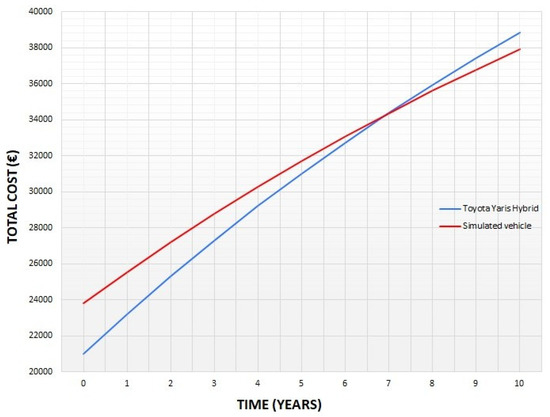
Figure 10.
Time history of LCC for the two models examined.
14. Conclusions
The purpose of this paper is, through a feasibility, reliability, and economic study, to propose an innovative solution within the Urban Transport System. The solution presented can therefore represent a valid and reliable medium-term solution for the city system, bringing benefits at the level of pollutant reduction and being competitive with both current “classic” hybrid configurations and ICE vehicles. The obtained results were overall very satisfactory and the car in both urban and suburban cycles proved to be up to expectations. Fuel consumption turned out to be very good in the city and excellent on the motorway and fast-moving roads, even better than the commercial hybrid vehicle, which makes this aspect one of its major strengths. From an economic point of view, the initial cost of the car is affected by the onerousness of the MGT but the versatility of the latter regarding the fuel supply allows significant annual savings in operating costs that lead, after a few years, to compensate for the higher initial price. We can conclude that the configuration proposed in this study is a valid alternative to the hybrid cars currently on the market, a technology that in the short and medium-term will certainly experience a significant increase in its diffusion given the increasingly stringent regulations also in the context of the individual cities and society’s greater attention to environmental issues.
Author Contributions
Conceptualization, R.C., F.T.; Methodology, R.C.; Software, R.C, F.T.; Formal Analysis, R.C.; Validation, R.C., F.T.; Writing-Original Draft Preparation, R.C.; Writing-Review & Editing, R.C.; Supervision, R.C.; Project Administration, R.C. All authors have read and agreed to the published version of the manuscript.
Funding
The study presented in this paper has been conducted within the frame of a broader project funded by the Italian Ministry of Research, Project PRIN 2017–sector PE8–2017X8RFLE.
Conflicts of Interest
The authors declare no conflict of interest.
Nomenclature
| A | Area ( |
| Range in electric mode (km) | |
| AC | Acquisition Cost (€) |
| B | Magnetic Flux (T) |
| C | Cost (€) |
| Capacity (Ah) | |
| Consumption of electric energy per kilometer (Wh/km) | |
| Aerodynamic drag coefficient | |
| CC | Cross Corrugated |
| CNG | Compressed Natural Gas |
| CPV | Cumulative Present Value |
| CU | Corrugated Undulate |
| CW | Cross Wavy |
| D | Distance (km) |
| DC | Direct Current |
| E | Energy (Wh) |
| E-CVT | Electrical Continuously Variable Transmission |
| EGR | Exhaust Gas Recirculation |
| EV | Electric Vehicle |
| Resistance coefficient | |
| FOC | Field-oriented Control |
| FTP | Federal Test Procedure |
| FV | Future Value |
| g | Gravity m/s2 |
| H | Height (m) |
| HEV | Hybrid Electric Vehicle |
| HSD | Hybrid Synergy Drive |
| HV | Hybrid Vehicle (Toyota Yaris Hybrid) |
| I | Current Intensity (A) |
| ICE | Internal Combustion Engine |
| IM | Induction Machine |
| L | Length (m)—Section 4.1; Inductance (H)—Section 4.2, Section 4.3, Section 4.4 |
| LCC | Life Cycle Cost |
| LHV | Lower Heating Value |
| Li-Ion | Lithium Ion |
| M | Mass (kg)—Section 2; Mutual Inductance (H)—Section 4 |
| MC | Maintenance Cost (€) |
| MGT | Micro gas turbine |
| NEDC | New European Driving Cycle |
| Number of Element | |
| NiMH | Nickel-metal Hydride |
| OC | Operating Cost (€) |
| p | Number of Pole Pairs |
| P | Power (W) |
| PFR | Plate Fin Recuperator |
| PMSM | Permanent-magnet Synchronous Machine |
| PSR | Primary Surface Recuperator |
| PV | Present value |
| sfc | Fuel Consumption (L/100 km) |
| SOC | State of Charge |
| SRM | Switched Reluctance Machine |
| T | Time (s) |
| T | Torque ( |
| V | Speed (km/h)—Section 4; Volume (—Section 5; Voltage (V)—Section 6 |
| W | Weight (kg) |
| WLTC | Worldwide harmonized Light vehicles Test Cycle |
| WLTP | Worldwide harmonized Light vehicles Test Procedure |
| ZEBRA | Zero Emissions Batteries Research Activity |
| Greek Symbol | |
| δ | Inertia factor |
| ρ | Density ( |
| Angle (°) | |
| High-heat Transfer efficiency | |
| Efficiency | |
| Angular position (°) | |
| Magnetic Flux (Wb) |
References
- Singh, K.V.; Bansal, H.O.; Singh, D. A comprehensive review on hybrid electric vehicles: Architectures and components. J. Mod. Transport 2019, 27, 77–107. [Google Scholar] [CrossRef]
- Pistoia, G. Electric and Hybrid Vehicles: Power Sources, Models, Sustainability, Infrastructure and the Market; Elsevier: Amsterdam, The Netherlands, 2010. [Google Scholar]
- Ehsani, M.; Gao, Y.; Emadi, A. Modern Electric, Hybrid Electric and Fuel Cell Vehicles. Fundamentals, Theory and Design, 2nd ed.; CRC Press: Boca Raton, FL, USA, 2010. [Google Scholar]
- Capata, R.; Coccia, A. Procedure for the design of a Hybrid-Series vehicle and the Hybridization Degree choice. Energies 2010, 3, 450–461. [Google Scholar] [CrossRef]
- Capata, R.; Sciubba, E. A Gas Turbine-Based Hybrid Vehicle-Part II: Technological and configuration issues. J. Eng. Gas Turbines Power 2003, 125, 777–782. [Google Scholar] [CrossRef]
- Capata, R.; Sciubba, E. An innovative solution for suburban railroad transportation: The gas turbine hybrid train. Int. J. Thermodyn. 2005, 8, 55–66. [Google Scholar]
- Capata, R. Urban and Extra-Urban Hybrid Vehicles: A Technological Review. Energies 2018, 11, 2924. [Google Scholar] [CrossRef]
- Mi, C.; Masrur, A. Hybrid Electric Vehicles: Principles and Applications with Practical Perspectives; Wiley: Hoboken, NJ, USA, 2018. [Google Scholar]
- Chau, K.T.; Li, W. Overview of electric machines for electric and hybrid vehicles. Int. J. Veh. Des. 2014, 64, 46–71. [Google Scholar] [CrossRef]
- Sato, E. Permanent magnet synchronous motor drives for hybrid electric vehicles. IEEJ Trans. Electr. Electron. Eng. 2007, 2, 162–168. [Google Scholar] [CrossRef]
- Wang, W.; Fu, R.; Fan, Y. Electromagnetic Parameters Matching of Permanent Magnet Synchronous Motor for Hybrid Electric Vehicles. IFAC-PapersOnLine 2018, 51, 407–414. [Google Scholar] [CrossRef]
- Takano, Y.; Takeno, M.; Hoshi, N. Design and analysis of a switched reluctance motor for next generation hybrid vehicle without PM materials. In Proceedings of the International Power Electronics Conference, Sapporo, Japan, 21–24 June 2010; IEEE Xplore: Piscataway, NJ, USA, 2010. [Google Scholar]
- Baltatanu, A.; Florea, L.M. Comparison of Electric Motors Used for Electric Vehicles Propulsion. In Proceedings of the International Conference of Afases, Brasov, Romania, 23–25 May 2013. [Google Scholar]
- Finken, T.; Felden, M.; Hameyer, K. Comparison of Electric Motors Used for Electric Vehicles Propulsion. In Proceedings of the 8th International Conference on Electrical Machines, Vilamoura, Portugal, 6–9 September 2008; IEEE Xplore: Piscataway, NJ, USA, 2008. [Google Scholar]
- Li, S. A Review of Electric Motor Drives for Applications in Electric and Hybrid Vehicles; Technical Report; Unpublished work; 2017. [Google Scholar]
- Parker GVM Global Vehicle Motor. Available online: https://www.parker.com (accessed on 28 June 2020).
- Raja Vignesh, C.R. A Gas Micro-Turbine Hybrid Vehicle. Preprint. 2018. Available online: https://doi.org/10.13140/RG.2.2.30694.11840 (accessed on 28 June 2020).
- Arav, B.L.; Shulman, R.; Kozminykh, V.A. Refinement of hybrid motor-transmission set using micro turbine generator. Procedia Eng. 2015, 129, 166–170. [Google Scholar] [CrossRef]
- Capstone C30 Data Sheets. Available online: https://www.capstoneturbine.com (accessed on 28 June 2020).
- Nascimento, M.A.R.; Oliveira, L.; Santos, E.; Batista Gomes, E.E.; Goulart Dias, F.L.; Velesques, I.G.; Miranda Carrillo, R.A. Progress in Gas Turbine Performance; Ernesto Benini Editore: Padova, Italy, 2013. [Google Scholar]
- Shah, R.K. Compact Heat Exchangers for Microturbines. In Proceedings of the Fifth International Conference on Enhanced, Compact and Ultra-Compact Heat Exchangers: Science, Engineering and Technology, Hoboken, NJ, USA, 11–16 September 2005. [Google Scholar]
- Xiao, G.; Yang, T.; Liu, H.; Ni, D.; Ferrari, M.L.; Li, M.; Luo, Z.; Cen, K.; Ni, M. Recuperators for micro gas turbines: A review. Appl. Energy 2017, 197, 83–99. [Google Scholar] [CrossRef]
- Aquaro, D.; Pieve, M. High Temperature Compact Heat Exchangers: Performance of Advanced Metallic Recuperators for Power Plants. In Proceedings of the Fifth International Conference on Enhanced, Compact and Ultra-Compact Heat Exchangers: Science, Engineering and Technology, Hoboken, NJ, USA, 11–16 September 2005. [Google Scholar]
- Noga, M.; Juda, Z. The application of nimh batteries in a light-duty electric vehicle. Tech. Trans. 2019, 12, 197–221. [Google Scholar] [CrossRef]
- Babu, A.; Ashok, S. Comparison of Battery Technologies for Hybrid Electric and Plug-in Hybrid Electric Vehicles. Trends Electr. Eng. 2012, 2, 1–10. [Google Scholar]
- Adel, B.; Youtong, Z.; Shuai, S. Simulation and Comparison of HEV Battery Control for Best Fuel Economy and Longer Battery Life. World Electr. Veh. J. 2010, 4, 421–426. [Google Scholar] [CrossRef]
- Iclodean, C.; Varga, B.; Burnete, N.; Cimerdean, D.; Jurchis, B. Comparison of Different Battery Types for Electric Vehicles. IOP Conf. Ser. Mater. Sci. Eng. 2017, 252, 012058. [Google Scholar] [CrossRef]
- Young, K.; Wang, C.; Wang, L.Y.; Strunz, K. Electric Vehicle Battery Technologies. In Electric Vehicle Integration into Modern Power Networks; Springer: New York, NY, USA, 2013. [Google Scholar]
- Catalogo Kokam Superior Lithium-ion Battery. Available online: http://kokam.com (accessed on 28 June 2020).


© 2020 by the authors. Licensee MDPI, Basel, Switzerland. This article is an open access article distributed under the terms and conditions of the Creative Commons Attribution (CC BY) license (http://creativecommons.org/licenses/by/4.0/).