Abstract
The number of large energy storage units installed in the power system has increased over the last few years. This fact remains closely linked to the increase in the share of renewable energy in electricity generation. This is necessary to maintain the stability of the grid, which is becoming increasingly difficult to maintain due to the growing number of renewable energy sources (RES). Energy production from these sources is difficult to estimate, and possible unplanned shortages and surpluses in production are the cause of voltage and frequency fluctuations, which is an undesirable state. Consequently, the use of energy storage not only contributes to the regulation of grid operation but can also, under appropriate conditions, constitute an additional load if too much energy is generated by RES, or the source when the generation from RES is insufficient. The main contributions of this paper are as follows: A presentation of practical results achieved by implementing two optimal control strategies for a 1 MW (0.5 MWh) battery energy storage (BES) cooperating with a large 144 MW photovoltaic farm. In the first case, the BES was used to generate curtailment at photovoltaic farm to avoid power grid overload. The second case focuses on maximizing profits from selling the energy produced in periods when the unit price for energy was the highest according to energy market forecasts. In both cases, the storage was used simultaneously to cover the producer’s own demand, which eliminated the costs associated with the purchase of energy from the operator, especially during the night supply. A technical and economic evaluation was prepared for both cases, considering the real profits from the investment. The potential of using the BES to increase the functionality of photovoltaic energy sources was determined and discussed in the paper.
1. Introduction
A modern power system, also called the smart grid, requires the implementation of innovative technological solutions by all energy participants as electricity consumers, distributers, transmission grid operators, and energy producers, for example, in energy-efficient equipment, intelligent buildings, and home PV installations. Power system operators, within the framework of power distribution regulation, must operate in their own area, i.e., using optimal strategies to manage instantaneous active and reactive power effectively. Consequently, methods for congestion management have been developed, such as redispatch and feed-in management. The overall energy used in redispatch in Germany has risen by over 300%, from 4.96 to 20.44 TWh between 2012 and 2017 [1]. The curtailed energy from renewable energy sources (RES) has concurrently increased by more than fourteen times, from 390 MWh in 2012 to 5.52 TWh in 2017 [2]. All methods regarding network and system security combined to over 1.5 billion EUR in 2017 [1]. In addition, according to EU directives and regulations [3,4], electricity grid operators are obliged to connect all new RES into the grid. These actions are often associated with the need to expand both the distribution and transmission of the grid, which increase its complexity and contribute to the increasing dynamics of the energy system. It is necessary to cooperate and integrate new functionalities and elements which are complementary to smart grid technology to properly control power distribution and stable and safe operation of the power grid involving RES [5,6,7]. This technology includes energy meters [8], energy storage and electric vehicles [9,10], and other technologies and techniques which increase the flexibility of the power system [11,12].
Energy storage has recently been increasingly used in the distribution network to improve the quality of electricity supply [13] and to ensure the uninterrupted operation of conventional and renewable sources [14]. The cooperation of types of energy storage with the power grid is connected with a particular way of planning their distribution (voltage level), defining their type, tasks, and required capacity to provide system services. An overview of types of energy storage is presented in Table 1.

Table 1.
Different types of storage utilization depending on the voltage level [15].
Research on the types of energy storage in the power system is still being carried out by a wide group of researchers worldwide. Numerous works published in recent years in international scientific journals confirm this. Hybrid systems with RES, such as [16], where the sizing of cooperating pumped hydro storage and PV generation units is described, and [17], where authors described an optimum size economic model of a wind powered pumped hydro storage system, showing the advantages of combining RES with energy storage. Apart from large pumped storage hydropower (PSH) systems, thermoelectric energy storage (TEES) is also used in the power system. Thus, Henchoz et al. [18] analyzed the TESS–PV system thermoeconomically. At the same time, the authors demonstrated the possibility of using the potential of TEES for steady-state multi-objective optimization of a 50 MW plant, minimizing the investment costs and maximizing the energy storage efficiency, which is similar to that conducted in the context of this work. In addition, the utilization of RES and TEES is also carried out for smaller systems [19], where the management of heat and electricity is developed to optimally plan the main household appliances, generation, and storage components. The proposal in more advanced applications, such as producing electricity exclusively from RES and converting it into other energy forms to satisfy the multiple energy needs of a community is shown in Bruno et al. [20], where a net-zero multi energy approach is described using RES and TEES. An adiabatic compressed air system (A-CAES) is another type of storage used in the power system. The technical benefits and corresponding operational costs of an A-CAES system based on the proposed model cooperating with RES were estimated in Lombardi et al. [21]. It is worth noting that the authors were assuming in the evaluation of the cost–benefit that the A-CAES did not operate as market driven. Another work which addresses the operational analysis issues related to the generation system was carried out by Abbaspour et al. [22]. In this paper, a wind farm with a similar concept of using storage to increase profits from electricity sales for two similar scenarios was analyzed. They show, as in this case, that there is a possibility of increasing profits from electricity generation depending on the control algorithm and market price information. In this field, a similar but applied approach is presented by using a different type of storage and electricity source. Flywheels are most commonly used to improve the reliability of supply, similar to that presented in Tomczewski and Kasprzyk [23], where the authors determine the minimum storage capacity required to maintain the accepted criteria for the reliability of the energy supply. Tomczewski et al. [24] focus on minimizing the unit discounted cost of electricity generation in a system containing a wind power plant and flywheel energy storage. Referring to the next type of storage, an off-grid DC network simulation was presented in Kalamaras et al. [25], where the authors used, apart from electrochemical energy storage, a hydrogen tank with fuel cells to reduce the cost of energy purchases. A different approach is presented Zhang et al. [26]. The authors focused on performing a Net Present Value and self-sufficiency ratio analysis to determine the profitability of two types of energy storage (hydrogen and battery) cooperating with a grid-connected PV farm and with known local load. Moreover, the analysis of costs related to the integration and operation of various hybrid systems using RES and hydrogen storage was also described in Wang et al. [27].
Considering battery energy storage (BES), similar work to this was carried out by Małkowski et al. [28], where the analysis the cooperation of BES with the PV system has also been conducted. In this work, authors used a 25 kWh energy storage integrated with a PV system with a smaller output power (33 kW) which operated as part of a day-ahead market. Moreover, Ranaweera and Midtgard [29] and Hemmati and Saboori [30] dealt with similar economic analyses and operational cost optimization for a hybrid BES–PV system, for which a major and achievable potential of utilizing residential storage for grid load levelling was identified. The difference compared to this article is the analysis for small installations in households. Another work which is also worth focusing on is research conducted by Koller et al. [31], where an electrochemical storage with similar output parameters and power value has been installed in a building’s load circuit, enabling frequency control, peak shaving, and the possibility of operating the storage in an island mode with cooperating diesel motors. Moreover, similar to Consiglio et al. [32], the efficiency of the large battery storage facility was determined based on actual measurements. In contrast to Koller et al. [31], the BES system examined in this paper is considered in terms of maximizing profits from the sale of electricity from a solar power plant while Hemmati and Saboori [30] focus on ensuring the reliability, power quality of the customer, and shaping the load curve. According to this study and Koller et al. [31], the lifetime and degradation process of the cells of the BES were not analyzed.
This work consists of an economic analysis which determines the impact of using the storage facility to control the generation (power curtailment) of a PV farm and determines the possibility of operating the PV farm in a self-sufficient mode throughout the day and night. The main contribution of this work is to determine the benefits of integrating a BES and a large PV farm with the implementation of various control algorithms according to use cases A and B. The algorithm was aimed at maximizing profits from energy production, similar to the work of Komarnicki [33], and minimizing electricity production costs [34,35]. The results based on the algorithms accepted and the evaluation of cost-effectiveness were estimated. Moreover, the paper describes the methodology for determining the optimum value of the storage capacity but, in this case, it was not implemented because a ready-made technological solution in the form of a storage with a given capacity was used.
In addition, many scientific papers could be found focusing on optimal sizing of the storage’s energy capacity [36,37] and optimal placement of the storage [38], which are not the aim of this study. Projects related to energy management in the distribution network are also very popular [39], including broadly defined regulation of network parameters [31,40], allowing for their utilization in wind farm regulation process [41] and the production of photovoltaic farms [42,43,44]. A noteworthy issue in the practical integration of BES in the power system is not only their electrical connection but also communication and related aspects of data exchange, protocols, and standards which are described in Hänsch et al. [45]. All these authors have faced the similar problem of energy storage implementation with RES. They have tried to determine the potential benefits of this cooperation by analyzing the results of their simulations, creating accurate models, determining optimal parameters, or performing field measurements on real objects. This work focuses on the analysis of the functioning of the PV–BES system based on measurements of operational parameters in a real field test.
Section 2 defines the method of energy storage sizing depending on the local load condition with which the storage is operating. Section 3 describes the construction of the BES system used, including the connection to the photovoltaic farm and its communication architecture allowing for the exchange of valuable information. Section 4 details two analyzed cases of cooperation between the storage and the PV farm, including a comparison of the potential financial benefits of using an appropriate control algorithm. Section 5 presents the final conclusions from the conducted work.
2. Usage of Energy Storage Systems and Sizing Methodology
Energy storage is one of the elements of the power system, the use of which is associated with increasing the independence of network operation but also involves additional investment costs. These costs for highly specialized systems may be economically unprofitable in certain specific cases, although they may allow the maintenance of system stability in case of disruption. Therefore, the optimum value of the energy storage capacity could be estimated and determined in order to minimize costs.
Storage consisting of packets of Li-ion cells can reach a capacity of several megawatts, which allows them to be used to control the system operation composed of renewable sources and allows the parameters (voltage, frequency, active power and reactive power) of this system to be controlled. As with other types of energy storage, these systems should be optimally sized in terms of power and energy capacity by using the input characteristics and residual load curve, i.e., considering both energy demand and generation from “must-run” conventional units, as shown in Figure 1.
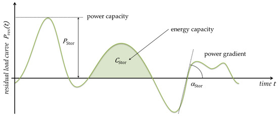
Figure 1.
Storage parameters from battery load curve.
Battery power for a specific charging/discharging period x can be determined by analyzing the power flow which must be covered during this period by BES and determining the maximum power for each time section according to Formula (1) [41]. The total number of battery usage periods investigated is determined by i.
It is also possible to determine the power gradient for BES, which can be calculated using Formula (2). This gradient allows one to determine the power change ratio in time periods in a certain usage period x. The overall number of power gradients in all usage periods is determined by j.
The capacity of the system is determined based on energy stored in a period x, considering the maximum charging and discharging power. The value of the energy capacity can be determined from Formula (3) for all l usage periods [34].
The total power and capacity of the BES can be determined from (1), (2), and (3), which refer to and for a given period of the set under analysis. Even though the general number of usage periods is the same for , , and , different indexes are introduced as values for each parameter may occur multiple times. These duplicates have been neglected for further computing, which results in differing values for i, j, and l. The use of energy storage should also be economically viable. Therefore, vectors of the technical parameters, containing all determined values of power and energy capacity, as well as cost parameters are used to determine the investment cost KStor presented in Formula (4) [33,46,47,48]:
- —specific cost of battery storage capacity
- —specific cost of related power unit
- —overhead cost factor for utility components
In order to perform the simulation, it is also necessary to determine the battery life of , which can be determined by reference to the number of complete charge and discharge cycles. Based on this, annual savings can be calculated for various configurations of the energy storage system. The formula that allows one to determine the value of profits from the use of energy storage with the cooperating RES system—Formula (5)—can be defined using the relationships (4) [33].
3. System Analyzed
3.1. System Configuration and Grid Integration
Analysis of the developed practical application, assuming a reduction of electricity purchase costs, was carried out based on the measurements and considering the 1 MW BES with a total capacity of 478 kWh. The construction of the battery container is shown in Figure 2. The storage system consists of three compartments responsible for energy storage, process controls, and connection with the power grid. The energy storage is composed of a set of 5040 lithium-ion cells connected in eight parallel series, which are located in an air-conditioned compartment with a constant ambient temperature. The control of processes occurring during battery operation is connected with the monitoring system and transformers, fire protection, supervision, and a communication system. Two transformers on two voltage levels could realize the power flow between the energy storage and the power grid: low voltage (0.3/0.4 kV) and medium voltage (0.3/10 kV). The electrical energy storage also has two 500 kW inverters with common regulation.
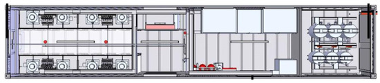
Figure 2.
Construction of a 1 MW lithium-ion battery system for grid applications [49].
The battery installation was connected to the existing photovoltaic farm located near Berlin, Germany. The PV farm has been equipped with a transformer enabling the connection with BES at a low voltage level (0.3/0.4 kV). The cooperation of the BES with the farm involves the use of available capacity to determine the impact of specific scenarios on the energy production of the PV farm. The storage was connected with a separated part of the PV for testing purposes. Moreover, before the system was commissioned, all preparatory and operational works were performed (e.g., cable connections) and permission was obtained from the power grid operator.
3.2. Supervision and Communication System
An additional six Janitza Power Analyzers UMG 604 were installed in the battery infrastructure to accurately record the cooperation of all elements of the PV system and energy storage. The analyzer’s tasks included recording the active and reactive power generated by the PV system at one-minute intervals. The control and acquisition of data from the operation of the PV farm–BES has been implemented using the hardware and software arrangements shown in Figure 3.
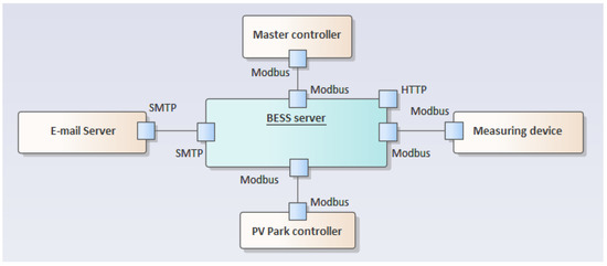
Figure 3.
Diagram of control and data recording systems in the supervision system considered.
The PV plant is equipped with an external component, which is responsible for controlling the power plant generation, including processes related to the regulation, control, and monitoring of the power grid integration in accordance with the guidelines of the network operator. The control and monitoring of the power distribution (active and reactive power) takes place via a control interface, skycontrol Remote Interface, which uses the Modbus protocol for communication. With this system, it is possible to download information in real time about active, reactive, and apparent power; this information is then stored in one-minute intervals on a server placed in the BES. In addition, the battery system is equipped with a master controller, which allows one to perform 281 measurements on the Modbus line. This controller also provides the ability to control energy storage functions intelligently. It allows one to start the charging of the energy storage or its discharging depending on the value of active and reactive power required by the operators in the power grid. An additional element that has been added to the communication system is the e-mail server (SMTP protocol), by means of which it is possible to obtain information about any errors occurring during the operation or failures of the device.
An important element of the BES system is a server which consists of three blocks representing a given component. The communication architecture is shown in Figure 4. The server’s tasks include the reading of data measured from the master controller and from six power quality analyzers. In addition, the server collects information about electricity generation from a PV farm. The information is retrieved by the Modbus communication server element and then stored in the MySQL database. The Web Server component provides the ability to display the current values measured and historical data via a network interface. It is also possible to control the operation of the entire BES remotely using this system.
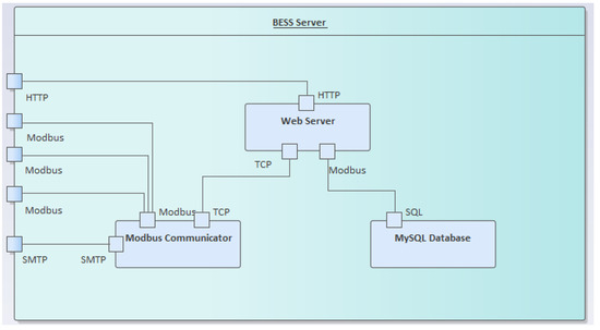
Figure 4.
Diagram of the battery energy storage (BES) communication architecture.
4. Controllability Developed
As a result of connecting the BES to the PV farm, four strategies of energy storage control algorithms were implemented depending on the PV farm generation. Two of them are described in Komarnicki [33], in which the assumptions adopted were discussed in detail and the results of analyses were presented. The remaining two variants are presented in this article and concern energy generation strategies in the solar power plant with specific control parameters. The installed nominal capacity of the PV generator is 144 MW in total, divided in different sections. The electrochemical energy storage was connect in the form of a 478 kWh Li-ion battery and with maximum power of 1 MW in a 77 MW PV array. The energy storage was used to reduce the costs associated with electricity consumption by the farm at night when it consumes an average of 350 to 450 MWh of electricity per year. The analyses were based on measurement data, which allowed conducting the necessary calculations using Microsoft Office and MATLAB environment.
4.1. Study Case A
In the first variant, energy generation from a solar farm is limited due to network conditions (network overloads). If the supply grid is not able to absorb the full generation due to other load flows, the PV park generation is limited to . The difference between the maximum power and the power resulting from the limitation could be used for charging the BES process, HVAC systems, and covering the PV farm’s own demand. The reserve capacity is calculated for each day since the cooling system’s power demand must be covered until the beginning of the next day’s generation period. This is based on the period between the end of the generation period of the current day and the beginning of the generation period of the following day. This results in the reserve capacity required (average 90 kWh) and a corresponding minimum state-of-charge () for each day of the year. The control algorithms ensure that the battery is not discharged below the calculated reserve SOC. Additionally, if the amount of energy generated is not enough to charge the BES to a specific SOC value, the battery is recharged in the evening when production is limited (weather conditions) and the network demand for energy is small. During the night, the stored energy is used to sustain the power supply for the monitoring, control, and protection systems of the PV farm. The procedure of model operation is presented in Figure 5.
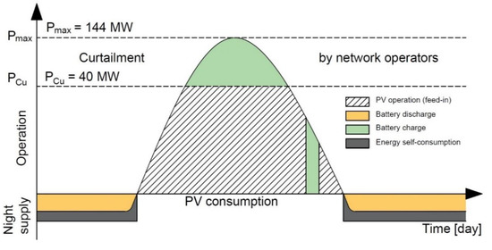
Figure 5.
Operation procedure of the PV farm in Germany with BES―study case A.
Furthermore, an economic analysis of the profitability of using the energy storage in the operation of the PV farm was carried out. Economic data accepted for the calculations is presented in Table 2.
Table 2.
Economic data for the adopted model.
The control system must work with a specific algorithm to implement the adopted model. The algorithm should consider the operating model of the PV farm and the current SOC level of the battery. Depending on the mode in which the PV farm is operating, the algorithm switches the BES accordingly. The scheme of the algorithm is shown in Figure 6.
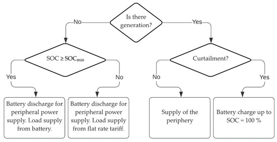
Figure 6.
Control algorithm for the adopted model.
The parameters necessary to perform the relevant calculations were adopted to make an economic analysis of the solution. These parameters are presented in Table 3. Based on the scenario results, a diagram of energy distribution was created between network elements, which is presented in Figure 7.
Table 3.
Techno-economic parameters for the adopted model.
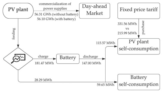
Figure 7.
Diagram of energy distribution in the power grid.
Energy production by the PV farm, without the BES, in the period under consideration is 56.31 GWh. In this case, the profile of charging the BES at specific times has been applied. The presence of the energy storage resulted in a reduction in energy production, which is resold to the energy market to the value of 56.10 GWh. However, the analysis shows that the overall balance is negative and significant reductions in energy losses can be observed. The list of model costs is presented in Table 4. The unit price of energy at the level of 161.5 €/MWh was adopted.
Table 4.
Results for the adopted model.
4.2. Study Case B
The monopoly on the production and sale of electricity was abolished in the nineteenth century. This created the possibility of a free market in which participants can compete with each other in the field of electricity supply to the recipient. The prices of energy produced currently depend on demand and energy production, i.e., on the daily schedule of energy demand. The process of changing energy prices during day and night allows the utilization of the energy storage to adjust production depending on the current market price for 1 kWh. Scenario B uses the BES, whose operation is related to the forecasted market situation. Figure 8 presents the principle of the functioning of the B scenario. Economic data adopted for the calculations is the same as that presented in Table 2.
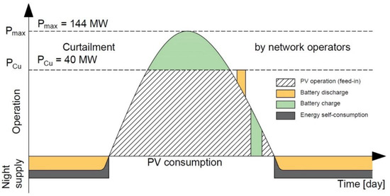
Figure 8.
Operation procedure of the PV farm in Germany with BES—study case B.
The BES control takes place in strictly defined hours related to current unit prices of electricity. The price of energy increases in the afternoon; this is related to the increase in energy consumption. During this period, it is beneficial to sell energy, including energy stored in the BES. The charging period was adopted depending on the season of the year and the energy storage starts charging at 15:00 for the winter season, at 17:00 for the interim, and at 19:00 for the summer. The simulation control system is based on the decision algorithm shown in Figure 9. Figure 10 presents the results of the simulation in the diagram. The simulation results are summarized in Table 5.
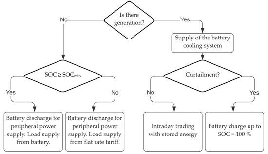
Figure 9.
Control algorithm for the adopted model.
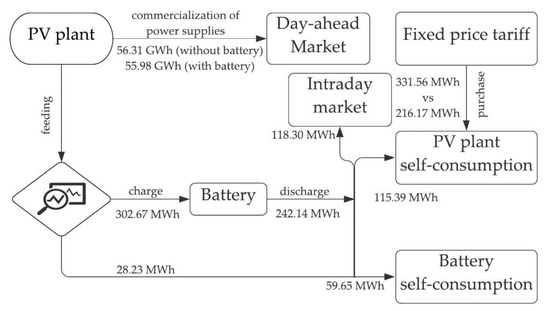
Figure 10.
Diagram of energy distribution in the power grid.
Table 5.
Technoeconomic parameters for the adopted model.
Based on the simulation, the potential profit was calculated depending on the electricity prices. The calculations include fluctuations and changes in energy prices over time. The scope of price changes was adopted in accordance with Figure 11. The costs and profits were presented in Table 6 based on the accepted energy price of 161.5 €/MWh, similar to the case in Section 4.1.
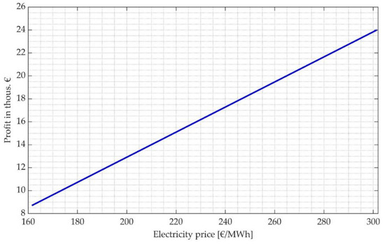
Figure 11.
A graph representing potential profits from the sale of energy depending on electricity prices.
Table 6.
Results for the adopted model.
In the second case, the BES for system applications, such as the regulation for power losses, is used during the time of the day according to the price of energy on the market. Time windows depend on weather conditions, and therefore, the time window is limited in winter due to shorter production time. The decision about charging or discharging the energy storage is made based on the signal received via the network interface. The signal is sent to the BES system and can take three states: “charging”, “discharging”, and “waiting.” Figure 12 presents the curve of the signal controlling operation of the 1 MW battery for study case B. The three states can be observed as follows: At 8:15, the control signal changes the status to “wait” and then goes into the status “discharging”. During this time, the battery has been already discharged such that the “discharging” command cannot be carried out (night discharge). Another control signal is “charge” in response to the current battery SOC. Appropriately, the discharge command is repeated between 11:45 and 12:00 and carried out as a result of the previous charging. A slight displacement of the control signal and BES system response can be seen in Figure 12. This is caused by different data resolutions—the control signal is registered in 1 min intervals and the Janitza analyzers record values at 15-min intervals.
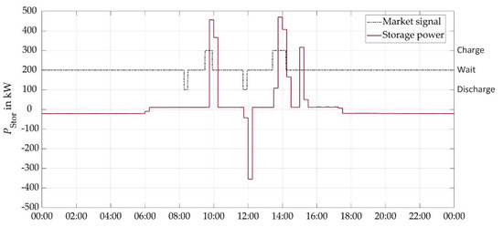
Figure 12.
Battery storage system operation using energy market information (2 March 2016).
4.3. Night Supply
The energy storage installed at the solar farm plays the role of a power source and covers the energy demand of the farm during the night in both cases. The energy demand results from the necessity of supplying the farm telecommunications systems, inverters, and control, protection, and automation systems. The amount of energy needed to power the PV farm during the night in the variants presented is known, and it is stored in the BES in accordance with the adopted algorithm (battery charging in the evening to the required SOC level).
Figure 13 shows an example of using batteries for a specific time interval. It can be observed that the battery is being charged with maximum power between 15:00 and 16:00. At the end of the charging state, the charging power drops. This is related to the protection of battery cells in order to avoid overloading. The energy storage status is changed at 18.00. From this point on, the BES is used to discharge a small amount of power to cover the PV farm’s own actual demand at night. The discharge process is scheduled for the entire night but is limited by the capacity of the battery which is used. There could be a situation in winter when the energy stored during the day cannot cover the demand during the night. In this case, the part of the farm examined is powered by the grid.
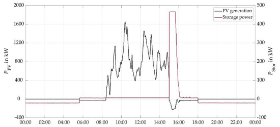
Figure 13.
Representation of the BES operation to cover the farm’s demand during the night (19 October 2015).
4.4. Discussion
In case A, the analysis showed a potential loss in the situation of using the energy storage exclusively to cover own needs at fixed electricity purchase and sale prices. Nevertheless, Figure 14 presents the relationship, which shows that it is profitable to cover the load from the stored energy if the purchase price of the energy from energy market is significantly higher than the energy sale price. Thus, in study case A, a 14.25% increase in the purchase price of energy compared to the sale price of energy allows reaching a break-even point where the power plant does not incur losses.
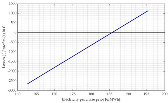
Figure 14.
Values of losses and profits depending on energy purchase price.
In the situation where operators pay compensation in the case of energy production limitations resulting from the need to limit the power flow, thus reducing overloads, this compensation will allow profits to be generated regardless of the energy storage utilization. A limitation in production occurs in both cases. However, the energy storage will allow for a significant increase in profits if the purchase price of electricity in the future increases, as can currently be seen on local electricity markets in European countries. Due to the limited production and unsold amount of electricity (3521.4 MWh), the profit may be even higher if it is compared with the assumed study case B.
5. Conclusions
This article focuses on the operational strategies of the Li-ion BES with renewable electricity sources (PV plants) connected to the power grid. The paper presents operation results corresponding to two optimal scenarios mentioned in the configuration above. A techno-economic analysis for determining the potential benefits of such integration is carried out and results are described and analyzed in the paper.
In the first case, the storage was used to reduce peak load energy generation to avoid overloads in the distribution network. As a result of the operation optimization using the adopted algorithm, the storage operation allowed us to relieve the overload of the distribution network, however, this kind of energy storage mode resulted in lower profits from whole energy sales. This situation is unfavorable for PV electricity producers, but it enables the proper functioning of the transmission and distribution system (system services). Therefore, it is necessary in such a case to use the existing regulatory potential while ensuring adequate financial compensation for producers.
In the second case, the functioning of the storage system was dependent on the current situation on the energy market. The storing of energy and its sale were closely related to the forecast prices for electricity on the exchange market. Such an approach made it possible to generate profits. The profits resulted largely from savings related to the use of the stored energy to cover the PV farm’s own needs during the night.
Selected cases show the real benefits of cooperation between the storage and a volatile energy source (a PV farm). It is possible to increase the functionality of the PV system (possibility of providing system services) by using appropriate algorithms and a well-adopted control system; nevertheless, in order to achieve these assumptions, it is necessary to manage the operation of both sources and storages properly as an integrated unit.
Author Contributions
Conceptualization, C.W. and S.B.; methodology, S.B. and P.L.; validation, B.A., C.W. and S.B.; formal analysis, C.W. and S.B.; investigation, B.A. and P.L.; resources, R.P. and C.W.; data curation, C.W.; writing—original draft preparation, R.P.; writing—review and editing, R.P., P.L. and L.K.; visualization, S.B.; supervision, P.K.; project administration, P.K.; funding acquisition, P.K. All authors have read and agreed to the published version of the manuscript.
Funding
This paper is partly a result of the project ACES (0350053B), funded by Federal Ministry for Economic Affairs and Energy according to a decision of the German Federal Parliament and part of the ERA-Net Smart Energy Systems initiative.
Conflicts of Interest
The authors declare no conflict of interest.
Abbreviations
| A-CAES | adiabatic compressed air energy storage |
| BES | battery energy storage |
| vector of length l and contains number of capacity values | |
| vectors containing ones in every position with length according to number of capacitance and power values (i,l) to open up the matrix containing all combinations of PStor and CStor | |
| HVAC | heating, ventilation, and air conditioning |
| Li-ion | lithium battery |
| NaS | sodium sulfur battery |
| vector of length i and contains all determined power values | |
| residual load power | |
| P2G | power-to-gas |
| PCu | curtailed power |
| PSH | pumped storage hydropower |
| PV | photovoltaic |
| RES | renewable energy sources |
| Rsave | yearly savings that can be evaluated for every power and capacity combination |
| Pred | profits from the energy storage utilization |
| SMES | superconducting magnetic energy storage |
| SOC | state of charge |
| TEES | thermoelectric energy storage |
| UPS | uninterruptible power supply |
References
- Bundesnetzagentur (BnetzA). Monitoringbericht 2019; Bundesnetzagentur Für Elektrizität, Gas, Telekommunikation, Post und Eisenbahnen: Bonn, Germany, 2019. [Google Scholar]
- Bundesnetzagentur (BNetzA). Available online: https://www.bundesnetzagentur.de/DE/Sachgebiete/ElektrizitaetundGas/Unternehmen_Institutionen/Versorgungssicherheit/Engpassmanagement/Redispatch/redispatch-node.htm (accessed on 18 May 2020).
- Directive (EU) 2018/2001 of the European Parliament and of the Council of 11 December 2018 on the Promotion of the Use of Energy from Renewable Sources. Available online: https://eur-lex.europa.eu/legal-content/EN/TXT/HTML/?uri=CELEX:32018L2001&from=EN (accessed on 23 April 2020).
- European Policies on Climate and Energy towards 2020, 2030 and 2050. Available online: https://www.europarl.europa.eu/thinktank/en/document.html?reference=IPOL_BRI(2019)631047 (accessed on 23 April 2020).
- Hauer, I.; Styczynski, Z.A.; Komarnicki, P.; Stotzer, M.; Stein, J. Smart grid in critical situations. Do we need some standards for this? A German perspective. In Proceedings of the IEEE Power and Energy Society General Meeting, San Diego, CA, USA, 22–26 July 2012. [Google Scholar]
- Parol, M.; Wójtowicz, T.; Księżyk, K.; Wenge, C.; Balischewski, S.; Arendarski, B. Optimum management of power and energy in low voltage microgrids using evolutionary algorithms and energy storage. Int. J. Electr. Power Energy Syst. 2020, 119, 105886. [Google Scholar] [CrossRef]
- Alemany, J.; Magnago, F.; Lombardi, P.A.; Arendarski, B.; Komarnicki, P. Multiobjective Optimization Model for Wind Power Allocation. Math. Probl. Eng. 2017, 2017, 1–10. [Google Scholar] [CrossRef]
- Wilcox, T.; Jin, N.; Flach, P.; Thumim, J. A Big Data platform for smart meter data analytics. Comput. Ind. 2019, 105, 250–259. [Google Scholar] [CrossRef]
- Stotzer, M.; Styczynski, Z.A.; Hansch, K.; Naumann, A.; Komarnicki, P. Concept and potential of electric vehicle fleet management for ancillary service provision. In Proceedings of the IEEE Grenoble PowerTech 2013, Grenoble, France, 16–20 June 2013. [Google Scholar]
- Wenge, C.; Komarnicki, P.; Styczynski, Z.A. Models and boundaries of data exchange between electric-vehicle and charging-point. Example of a practical realisation. In Proceedings of the 2010 Modern Electric Power Systems, Wroclaw, Poland, 20–22 September 2010. [Google Scholar]
- Alemany, J.; Arendarski, B.; Lombardi, P.; Komarnicki, P. Accentuating the renewable energy exploitation: Evaluation of flexibility options. Int. J. Electr. Power Energy Syst. 2018, 102, 131–151. [Google Scholar] [CrossRef]
- Powalko, M.; Komarnicki, P.; Rudion, K.; Styczynski, Z.A. Enhancing virtual power plant observability with PMUs. In Proceedings of the 5th International Conference on Critical Infrastructure, Beijing, China, 20–22 September 2010. [Google Scholar]
- Balischewski, S.; Wenge, C.; Komarnicki, P.; Wolter, M. Optimized operation of energy storages for primary control reserve. In Proceedings of the Conference on Sustainable Energy Supply and Energy Storage Systems 2018, Hamburg, Germany, 20–21 September 2018. [Google Scholar]
- Komarnicki, P.; Styczynski, Z.A.; Arendarski, B.; Trojan, P.; Bielchev, I. Zasobniki Energii—Integracja i wpływ na Prowadzenie Sieci Dystrybucyjnej (Energy storage—Integration and Impact on the Operation of the Distribution Network), Blackout a Krajowy System Energetyczny; Safety of the Polish Power System: Poznan, Poland, 2014; pp. 237–250. ISBN 978-83-7712-100-9. [Google Scholar]
- Komarnicki, P.; Arendarski, B.; Ramczykowski, M. Scenariusze rozwoju technologii magazynowania energii. E-Mobilność: Wizje i Scenariusze Rozwoju; Gajewskiego, J., Paprockiego, W., Pieriegud., J., Eds.; Centrum Myśli Strategicznych: Sopot, Poland, 2017; pp. 120–145. ISBN 978-83-945091-2-5. [Google Scholar]
- Liu, J.; Li, J.; Xiang, Y.; Hu, S. Optimal Sizing of Hydro-PV-Pumped Storage Integrated Generation System Considering Uncertainty of PV, Load and Price. Energies 2019, 12, 3001. [Google Scholar] [CrossRef]
- Bueno, C.; Carta, J.A. Wind powered pumped hydro storage systems, a means of increasing the penetration of renewable energy in the Canary Islands. Renew. Sustain. Energy Rev. 2006, 10, 312–340. [Google Scholar] [CrossRef]
- Henchoz, S.; Buchter, F.; Favrat, D.; Morandin, M.; Mercangöz, M. Thermoeconomic analysis of a solar enhanced energy storage concept based on thermodynamic cycles. Energy 2012, 45, 358–365. [Google Scholar] [CrossRef]
- Brahman, F.; Honarmand, M.; Jadid, S. Optimal electrical and thermal energy management of a residential energy hub, integrating demand response and energy storage system. Energy Build. 2015, 90, 65–75. [Google Scholar] [CrossRef]
- Bruno, S.; Dicorato, M.; La Scala, M.; Sbrizzai, R.; Lombardi, P.A.; Arendarski, B. Optimal Sizing and Operation of Electric and Thermal Storage in a Net Zero Multi Energy System. Energies 2019, 12, 3389. [Google Scholar] [CrossRef]
- Lombardi, P.A.; Röhrig, C.; Rudion, K.; Marquardt, R.; Estermann, A.S.; Styczynski, Z.A.; Voropai, N.I.; Müller-Mienack, M. An A-CAES pilot installation in the distribution system: A technical study for RES integration. Energy Sci. Eng. 2014, 2, 116–127. [Google Scholar] [CrossRef]
- Abbaspour, M.; Satkin, M.; Mohammadi-Ivatloo, B.; Hosseinzadehlotfi, F.; Noorollahi, Y. Optimal operation scheduling of wind power integrated with compressed air energy storage (CAES). Renew. Energy 2013, 51, 53–59. [Google Scholar] [CrossRef]
- Tomczewski, A.; Kasprzyk, L. Optimisation of the Structure of a Wind Farm—Kinetic Energy Storage for Improving the Reliability of Electricity Supplies. Appl. Sci. 2018, 8, 1439. [Google Scholar] [CrossRef]
- Tomczewski, A.; Kasprzyk, L.; Nadolny, Z. Reduction of power production costs in a wind power plant – flywheel energy storage system arrangement. Energies 2019, 12, 1942. [Google Scholar] [CrossRef]
- Kalamaras, E.; Belekoukia, M.; Lin, Z.; Xu, B.; Wang, H.; Xuan, J. Techno-economic Assessment of a Hybrid Off-grid DC System for Combined Heat and Power Generation in Remote Islands. Energy Procedia 2019, 158, 6315–6320. [Google Scholar] [CrossRef]
- Zhang, Y.; Campana, P.E.; Lundblad, A.; Yan, J. Comparative study of hydrogen storage and battery storage in grid connected photovoltaic system: Storage sizing and rule-based operation. Appl. Energy 2017, 201, 397–411. [Google Scholar] [CrossRef]
- Wang, F.-C.; Hsiao, Y.-S.; Yang, Y.-Z. The Optimization of Hybrid Power Systems with Renewable Energy and Hydrogen Generation. Energies 2018, 11, 1948. [Google Scholar] [CrossRef]
- Malkowski, R.; Jaskólski, M.; Pawlicki, W. Operation of the Hybrid Photovoltaic-Battery System on the Electricity Market—Simulation, Real-Time Tests and Cost Analysis. Energies 2020, 13, 1402. [Google Scholar] [CrossRef]
- Ranaweera, I.; Midtgard, O.M. Optimization of operational cost for a grid-supporting PV system withbattery storage. Renew. Energy 2016, 88, 262–272. [Google Scholar] [CrossRef]
- Hemmati, R.; Saboori, H. Stochastic optimal battery storage sizing and scheduling in home energy management systems equipped with solar photovoltaic panels. Energy Build. 2017, 152, 290–300. [Google Scholar] [CrossRef]
- Koller, M.; Borsche, T.; Ulbig, A.; Andersson, G. Review of grid applications with the Zurich 1MW battery energy storage system. Electr. Power Syst. Res. 2015, 120, 128–135. [Google Scholar] [CrossRef]
- Consiglio, L.; Di Lembo, G.; Noce, C.; Eckert, P.; Rasic, A.; Schuette, A. Performances of the first electric storage system of Enel Distribuzione. In Proceedings of the 22nd International Conference on Electricity Distribution, Stockholm, Sweden, 10–13 June 2013. [Google Scholar]
- Komarnicki, P. Energy storage systems: Power grid and energy market use cases. Arch. Electr. Eng. 2016, 65, 495–511. [Google Scholar] [CrossRef]
- Balischewski, S.; Hauer, I.; Wolter, M.; Wenge, C.; Lombardi, P.; Komarnicki, P. Battery storage services that minimize wind farm operating costs: A case study. In Proceedings of the IEEE PES Innovative Smart Grid Technologies Conference Europe (ISGT-Europe), Torino, Italy, 26–29 September 2017. [Google Scholar]
- Jiang, X.; Nan, G.; Liu, H.; Guo, Z.; Zeng, Q.; Jin, Y. Optimization of Battery Energy Storage System Capacity for Wind Farm with Considering Auxiliary Services Compensation. Appl. Sci. 2018, 8, 1957. [Google Scholar] [CrossRef]
- Pham, C.M.; Tran, Q.T.; Bacha, S.; Hably, A.; Nugoc, A.L. Optimal sizing of battery energy storage system for an island microgrid. In Proceedings of the IECON 2018—44th Annual Conference of the IEEE Industrial Electronics Society, Washington, DC, USA, 21–23 October 2018. [Google Scholar]
- Sharma, S.; Bhattacharjee, S.; Bhattacharya, A. Grey wolf optimisation for optimal sizing of battery energy storage device to minimise operation cost of microgrid. IET Gener. Transm. Distrib. 2016, 10, 625–637. [Google Scholar] [CrossRef]
- Montoya, O.; Gil-González, W.; Trujillo, E.R. Optimal Location-Reallocation of Battery Energy Storage Systems in DC Microgrids. Energies 2020, 13, 2289. [Google Scholar] [CrossRef]
- Komarnicki, P.; Lombardi, P.; Styczynski, Z.A. Electric Energy Storage Systems: Flexibility Options for Smart Grids, 1st ed.; Springer: Berlin/Heidelberg, Germany, 2017. [Google Scholar]
- Stroe, D.-I.; Knap, V.; Swierczynski, M.; Stroe, A.-I.; Teodorescu, R. Operation of a Grid-Connected Lithium-Ion Battery Energy Storage System for Primary Frequency Regulation: A Battery Lifetime Perspective. IEEE Trans. Ind. Appl. 2017, 53, 430–438. [Google Scholar] [CrossRef]
- Stenzel, P.; Schreiber, A.; Marx, J.; Wulf, C.; Schreider, M.; Stephan, L. Renewable energies for Graciosa Island, Azores—Life cycle assessment of electricity generation. Energy Procedia 2017, 35, 62–74. [Google Scholar] [CrossRef]
- Jannesar, M.R.; Sedighi, A.; Savaghebi, M.; Guerrero, J.M. Optimal placement, sizing, and daily charge/discharge of battery energy storage in low voltage distribution network with high photovoltaic penetration. Appl. Energy 2018, 226, 957–966. [Google Scholar] [CrossRef]
- Opiyo, N. Energy storage systems for PV-based communal grids. J. Energy Storage 2016, 7, 1–12. [Google Scholar] [CrossRef]
- Klabunde, C.; Moskalenko, N.; Styczynski, A.Z.; Lombardi, P.; Komarnicki, P. Use of energy storage systems in low voltage networks with high photovoltaic system penetration. In Proceedings of the IEEE Eindhoven PowerTech, Eindhoven, The Netherlands, 29 June–2 July 2015. [Google Scholar]
- Hansch, K.; Naumann, A.; Wenge, C.; Wolf, M. Communication for battery energy storage systems compliant with IEC 61850. Int. J. Electr. Power Energy Syst. 2018, 103, 577–586. [Google Scholar] [CrossRef]
- Battke, B.; Schmidt, T.S.; Grosspietsch, D.; Hoffmann, V.H. A review and probabilistic model of lifecycle costs of stationary batteries in multiple applications. Renew. Sustain. Energy Rev. 2013, 25, 240–250. [Google Scholar] [CrossRef]
- Lombardi, P.A.; Schwabe, F. Sharing economy as a new business model for energy storage systems. Appl. Energy 2017, 188, 485–496. [Google Scholar] [CrossRef]
- Lombardi, P.; Styczynski, A.Z. Electric energy storage systems: Review and modelling. In Proceedings of the CIGRE 2011 Bologna Symposium—The Electric Power System of the Future: Integrating Supergrids and Microgrids, Bologna, Italy, 13–15 September 2011. [Google Scholar]
- Lombardi, P.; Wenge, C.; Balischewski, S.; Komarnicki, P. Collected experiences from the Fraunhofer Institute IFFl’s Smart Grid Laboratory. In Proceedings of the AEIT International Annual Conference, Bari, Italy, 3–5 October 2018. [Google Scholar]
© 2020 by the authors. Licensee MDPI, Basel, Switzerland. This article is an open access article distributed under the terms and conditions of the Creative Commons Attribution (CC BY) license (http://creativecommons.org/licenses/by/4.0/).