Article

A Generalized Approach to the Steady-State Efficiency Analysis of Torque-Adding Transmissions Used in Renewable Energy Systems

1
Renewable Energy Systems and Recycling R&D Centre, Transilvania University of Brasov, 500036 Brasov, Romania
2
Design of Mechanical Elements and Systems R&D Centre, Transilvania University of Brasov, 500036 Brasov, Romania
3
Department of Engineering, College of Science and Engineering, Texas A & M University Corpus Christi, Corpus Christi, TX 78412, USA
*
Author to whom correspondence should be addressed.
Energies 2020, 13(17), 4568; https://doi.org/10.3390/en13174568
Submission received: 14 July 2020 / Revised: 27 August 2020 / Accepted: 31 August 2020 / Published: 3 September 2020
(This article belongs to the Section A3: Wind, Wave and Tidal Energy)

Abstract

:
The paper presents a general approach to the steady-state efficiency analysis of one degree of freedom (1-DOF) speed increasers with one or two inputs, and one or two outputs, applicable to wind, hydro and marine-current power generating systems. The mechanical power flow, and the efficiency of this type of complex speed increasers, are important issues in the design and development of new power-generating systems. It is revealed that speed increases, with in-parallel transmission of the mechanical power from the wind or water rotors to the electric generator, have better efficiency than serial transmissions, but their efficiency calculus is still a challenging problem, solved in the paper by applying the decomposition method of complex speed increasers into simpler component planetary gear sets. Therefore, kinematic, steady-state torque and efficiency equations are derived for a generic 1-DOF speed increasers with two inputs and two outputs, obtained by connecting in parallel two gear mechanisms. These equations allow any speed increaser to be analysed with two inputs and one output, with one input and two outputs, and with one input and one output. We discuss a novel design of a patent-pending planetary-gear speed increaser, equipped with a two-way clutch, which can operate (in combination with the pitch adjustment of the rotors blades) in four distinct configurations. It was found that the mechanical efficiency of this speed increaser in the steady-state regime is influenced by the interior kinematic ratios, the input-torque ratio and by the meshing efficiency of its individual gear pairs. The efficiency of counter-rotating dual-rotor systems was found to be the highest, followed by systems with counter-rotating electric generator, and both have higher efficiency than conventional systems with one rotor and one electric generator with fixed-stator.

1. Introduction

Among the renewable energy technologies, hydro and wind energy conversion systems currently have the largest share of electrical power generation worldwide [1,2]. While, hydro-electric power is a more mature technology, improvements to wind, tidal-stream and marine-current energy conversion systems are reported every year [3,4]. The major research has looked at energy-conversion efficiency for the purpose of maximizing the use of the onsite renewable potential. Moreover, in the case of wind and hydro-power systems of medium and high capacity, power is transmitted from the wind or water turbine to the electric generator via a speed increaser, which amplifies the speed of the turbine shaft approximately three times in case of hydro-electric systems, and by around one hundred in case of wind power systems [5,6,7]. The best performing speed increasers in use, are one degree of freedom (1-DOF) or two degrees of freedom (2-DOF) planetary transmissions, which achieve higher efficiency, higher transmission ratios and smaller overall sizes than fixed-axis transmissions. However, these benefits come with added complexity, making the respective transmissions more difficult to design and optimize.
Many innovative solutions of wind and tidal turbines have been proposed in recent years (Figure 1), such as counter-rotating rotors [8,9,10,11,12,13,14,15,16,17,18,19], high-performance mechanical transmissions [3,20] and more compact and efficient electric generators, including the counter-rotating type [21,22]. Shin [8] proposed a large capacity wind turbine that uses multiple, smaller rotors in a spatial arrangement and a high-efficiency planetary speed increaser. Wacinski [11], Brander [12], Climescu et al. [13] and Oprina et al. [16] proposed different solutions of horizontal-axis wind turbines with two coaxial, counter-rotating rotors. Didane et al. [15,19] and West [18] evaluated the performance of new concepts of vertical-axis wind turbines with counter-rotating coaxial rotors. Designers of counter-rotating turbines (CRT) have resorted to a wide variety of innovative solutions of speed increasers, such as variable transmissions [23], differential transmissions with electric motor speed control [24], or novel planetary gears [25,26,27,28]. In spite of their larger size and lower efficiency, compared to their planetary counterparts, the most common solution of speed increasers implemented in wind, hydro and marine-current power generating systems, including of the CRT type, are fixed-axis gear mechanisms [29,30,31].
Planetary speed increasers are more appropriate for CRT applications because they ensure higher kinematic ratios and reduced overall size, at higher efficiency levels [11,13,25,26,32,33,34,35,36,37,38,39,40,41]. Furthermore, CRTs can employ 2-DOF transmissions to sum the input speeds [35,39] or 1-DOF planetary transmissions to sum the input torques of their two rotors [40,41]. The first type of speed increaser has been studied in conjunction with CRT and conventional generator [42,43,44,45,46,47,48], or with CRT and counter-rotating electric generator [41]. No generalization has been proposed. Rather, particular designs have been presented and analysed with respect to their performance. The 1-DOF planetary speed increasers with multiple inputs and outputs can operate both, with single or with counter-rotating wind or water rotors, and with conventional (fixed stator) or counter-rotating, (moving stator) electric generator [49,50,51]. Efficiency analysis of the mechanical transmissions used in wind, tidal-stream and marine-current energy conversion systems is an essential part of their design and development process [52,53].
Based on the literature survey, the authors concluded that a comprehensive analysis of two-input, one degree of freedom planetary transmissions applicable to wind and water turbines is necessary, aiming to model the speed increaser efficiency in steady-state regime.
The paper proposes a generic class of 1-DOF transmissions, with two inputs and two outputs, employing two planetary gear mechanisms connected in parallel. All four possible combinations, i.e., with one or two input rotors, and with one or two generator outputs can be obtained as particular cases. In Section 2, steady-state torque and efficiency equations are derived for this generic speed increaser class with two inputs and two outputs. Three other types of speed increasers, i.e., with two inputs and one output, with one input and two outputs, and with one input and one output are discussed in Section 3 as particular cases. A novel planetary speed increaser with cylindrical gears, which can operate in four variants by means of a two-way clutch [54], is analysed in Section 4 using bivariate three-dimensional (3D) plots. The paper ends with a summary of results and conclusions.
The main contributions of this paper involve the proposed 1-DOF speed increaser class that can operate in four functional cases. To the best of our knowledge, it is the first unifying modeling of transmission performance in different functional cases. The application example is done for a novel design of a patent-pending transmission [54]. The performance study of the transmission is outlined in this paper by using bivariate plots.

2. Problem Formulation

It is known that mechanical transmissions where power is transmitted in parallel, also known as split-power transmissions, have higher efficiency than transmissions formed with mechanisms connected in series [51]. The same applies to speed increasers used in wind, hydro and marine-current power generating systems that integrate two counter-rotating wind or water rotors and/or one counter-rotating electric generator. A 1-DOF transmission consisting of two 1-DOF mechanisms M1 and M2 is assumed, providing serial (Figure 2a) or in-parallel transmission (Figure 2b,c) of the mechanical power from one rotor (R) or from two counter-rotating rotors (R1 and R2) to a standard electric generator (G) with a fixed stator, or to a generator with counter-rotating rotor (GR) and moving stator (GS). Mechanisms M1 and M2 are characterized by their kinematic ratios i1 and i2, and efficiencies η1 and η2. Each shaft x has an angular velocity ωx and transmits a torque Tx (where x is either R, R1, R2, G, GR or GS).
As explained in references [26,40,51], the efficiencies of the 1-DOF mechanical transmissions have been determined in closed-form, from kinematic, torque equilibrium and energy conservation considerations using Maple computer algebra system.
The efficiencies of the 1-DOF mechanical transmissions in Figure 2 are calculated as follows.
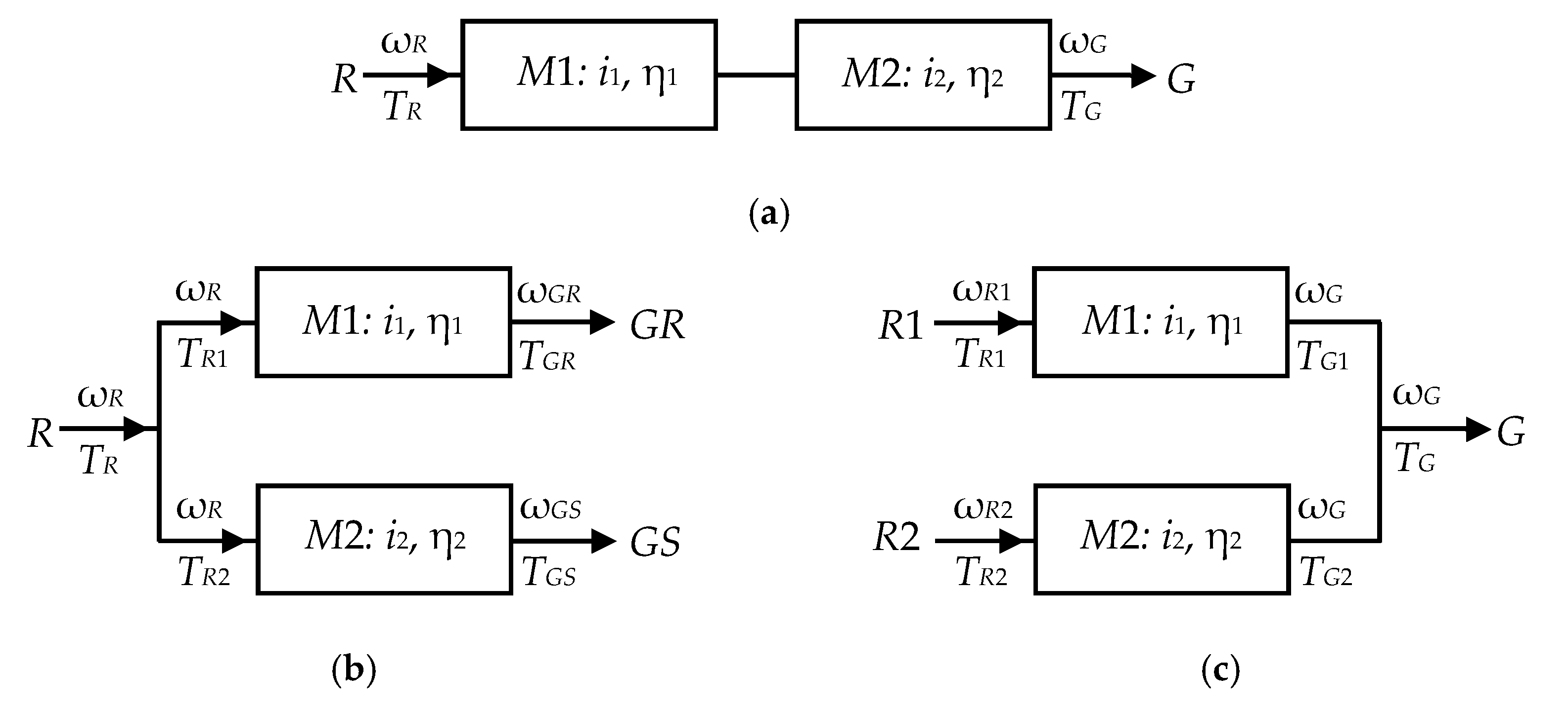
  • Case A (Figure 2a): speed increaser with one input (R) and one output (G) for which,
    ω G = ω R i 1 i 2 ;   T G = i 1 i 2 η 1 η 2 T R
    the efficiency is:
    η A = P G P R = T G ω G T R ω R = η 1 η 2
  • Case B (Figure 2b): speed increaser with one input (R) and two outputs (GR and GS) with:
    ω G R = ω R i 1 ;   ω G S = ω R i 2 ;   ω G = ω G R ω G S = i 2 i 1 i 1 i 2 ω R
    T R 1 = T G R i 1 η 1 ;   T R 2 = T G S i 2 η 2 ;   T R = T R 1 + T R 2
Knowing that the torques transmitted to the rotor and to the moving stator of the electric-generator are equal but of opposite signs (TGS = ‒TGR), the torque TG = TGR and mechanical power TG ωG delivered to the electric generator are:
T G = T R i 1 i 2 η 1 η 2 i 1 η 1 i 2 η 2   and   T G ω G = η 1 η 2 i 2 i 1 i 1 η 1 i 2 η 2 T R ω R
These equations allow the efficiency of the transmission to be calculated as:
η B = P G P R = T G ω G T R ω R = η 1 η 2 i 1 i 2 i 1 η 1 i 2 η 2
  • Case C (Figure 2c): speed increaser with two inputs (R1 and R2) and one output (G).
    ω G = ω R 1 i 1 = ω R 2 i 2 ;   ω R 2 = i 2 i 1 ω R 1
    T G 1 = i 1 η 1 T R 1 ;   T G 2 = i 2 η 2 T R 2 ;   T G = T G 1 + T G 2
    T G ω G = i 1 η 1 T R 1 + i 2 η 2 T R 2 i 1 ω R 1
    from where the efficiency of the transmission is calculated as:
    η C = P G P R = T G ω G T R 1 ω R 1 + T R 2 ω R 2 = i 1 η 1 i 2 η 2 k t i 1 i 2 k t
    where kt is the input torque ratio:
    k t = T R 2 T R 1
Assuming for convenience that the two component mechanisms M1 and M2 have equal efficiencies (η1 = η2 = η) Equations (2), (6) and (10) become:
η A = η 2 ;   η B = η ;   η C = η
Equation (12) suggests that if mechanisms M1 and M2 have comparable efficiencies, the use of counter-rotating wind or water rotors, or of counter-rotating generator, results in better efficiencies compared to serial arrangements i.e., ηB > ηA and ηC > ηA. In the next section, a general model for the efficiency analysis of a class of 1-DOF planetary speed increasers with two inputs and two outputs, consisting of two in-parallel planetary gear sets will be presented.

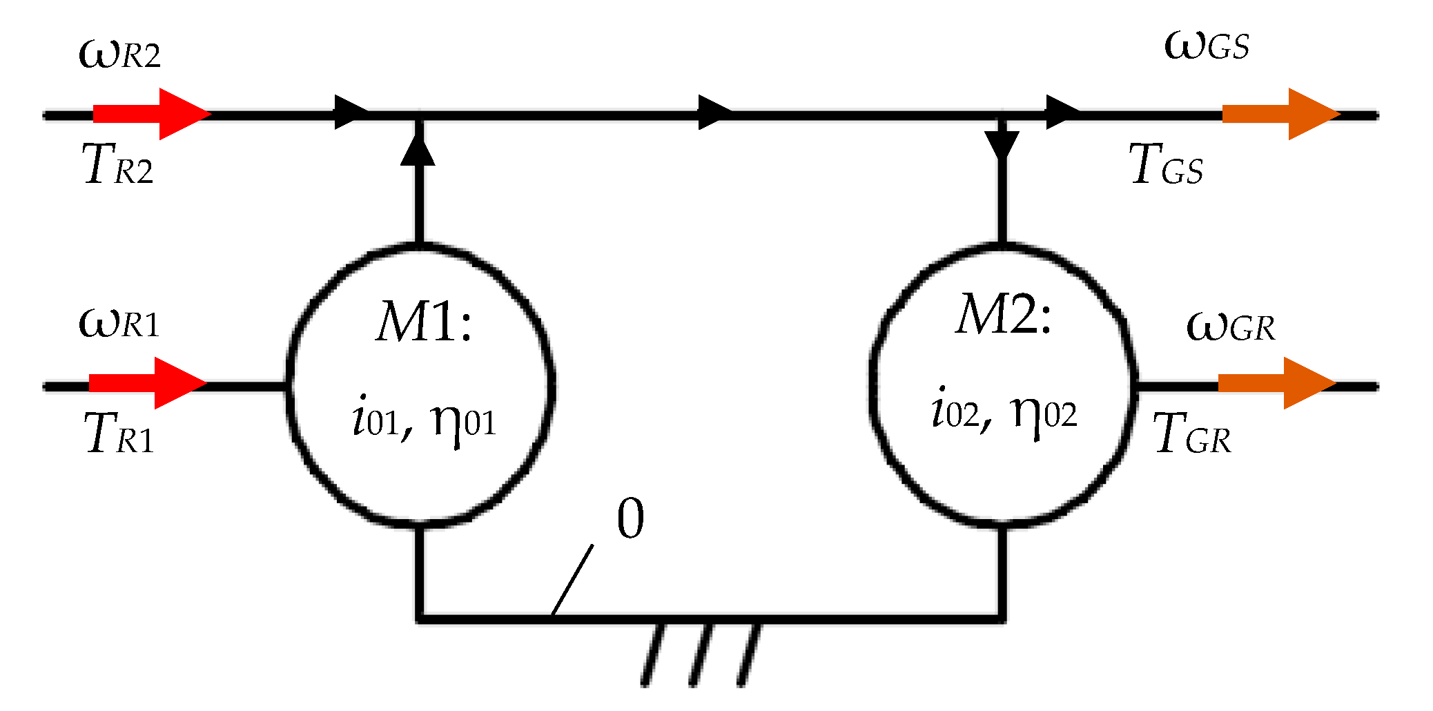
3. Generalized Speed and Steady-State Torque Equations for 1-DOF Speed Increasers with Two Inputs and Two Outputs

Figure 3 shows a general case of a 1-DOF speed increaser with two inputs and two outputs, obtained by connecting in parallel two planetary gear sets M1 and M2. The main input will be from the primary wind or water-turbine rotor R1, while the main output will be the generator rotor GR. The two planetary gear sets are connected through two links, one to the frame (i.e., body 0), and the second to both the secondary input-rotor R2 and to stator GS of the electric generator. The other input is connected to the primary rotor R1, while the electric generator rotor (GR) is connected to the other output.
With either the sun gear or planet carrier hold fixed to the frame, the two planetary gear sets M1 and M2 become 1-DOF mechanisms. Due to the constraints introduced by connecting the output of M1 to the input of M2, the speed increaser with two inputs and two outputs (L = 4) will have one degree of freedom.
Four functional variants of the 1-DOF speed increaser in Figure 3 are possible, depending on how the inputs and the outputs of the mechanism are activated:
(1)
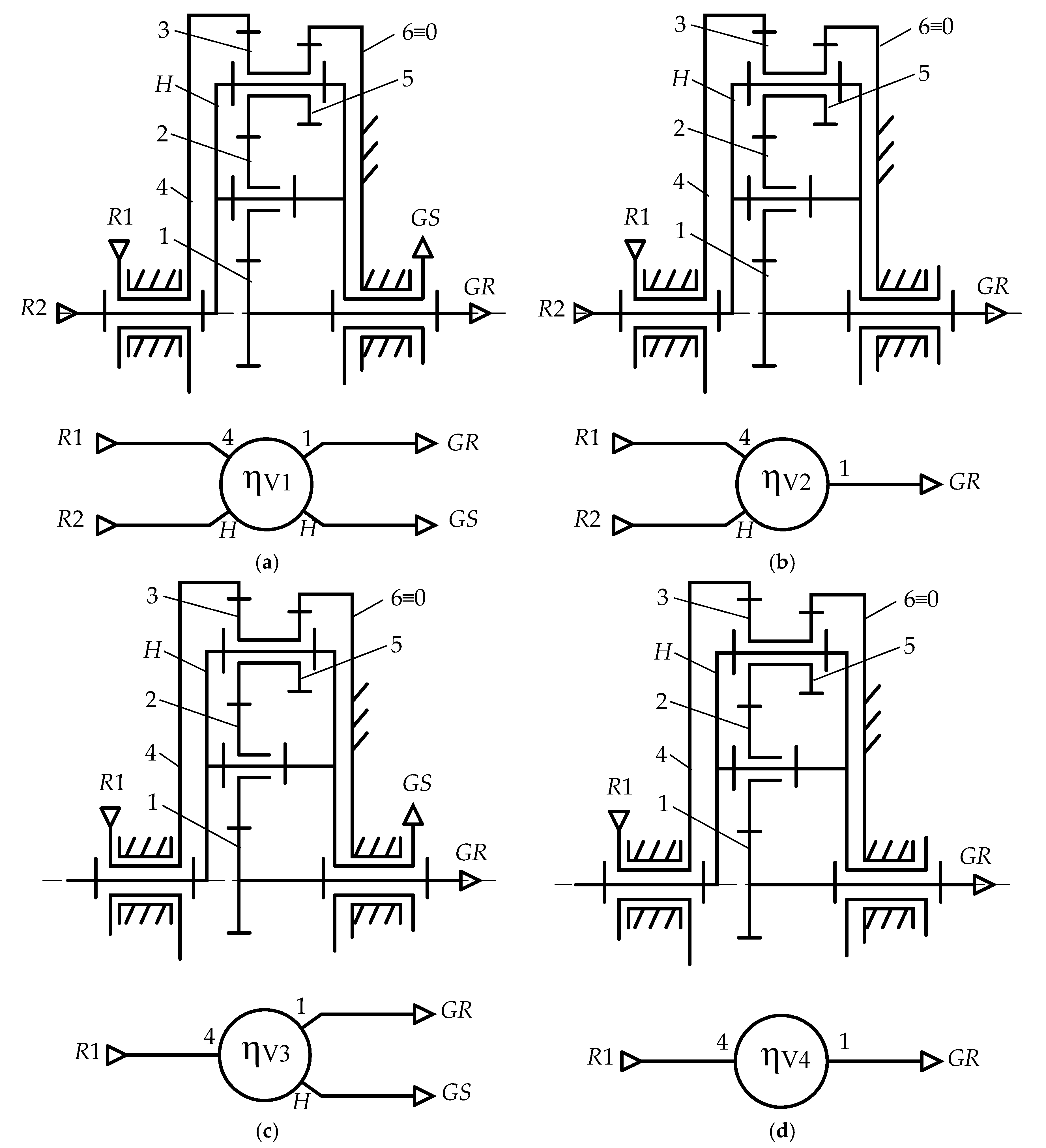
Variant V1: where both inputs R1 and R2, and both outputs GR and GS are active (L = 4). A system with two counter-rotating rotors and one counter-rotating electric generator is obtained.
(2)
Variant V2: where both inputs R1 and R2 and the electric-generator output GR are active (L = 3). In this case, a system with two counter-rotating rotors and a standard electric generator with ωGS = 0 is obtained.
(3)
Variant V3: where the main input R1 and both outputs are active (L = 3), case in which a system with one rotor (TR1 ≠ 0 and TR2 = 0) and one counter-rotating electric generator is obtained.
(4)
Variant V4: where only the main input R1 and the main output to the generator rotor GR are active (L = 2). This results in a system with one rotor (TR1 ≠ 0 and TR2 = 0) and a standard electric generator with ωGR ≠ 0 and ωGS = 0.
A 1-DOF mechanism with two inputs and two outputs (L = 4) is characterized by the following kinematic and static properties [51]:
(1)
It has one independent external angular velocity, with ωR1 assumed the independent kinematic parameter;
(2)
It has three angular-velocity transmission functions, i.e., three of the external angular velocities depend on the independent velocity i.e., ωR2 = ωR2R1), ωRG = ωRGR1), ωGS = ωGSR1);
(3)
It has one torque-transmission function TR1 = TR1 (TR2, TGR, TGS) i.e., one dependent external torque (the primary rotor torque TR1) and three independent external torques i.e., TR2, TGR and TGS.
It is also known that these transmission functions are linear, except for non-circular gears. As a result, the transmission functions for angular velocities can be written as,
ω G R = a ω R 1 ;   ω R 2 = b ω R 1 ;   ω G S = c ω R 1
where coefficients a, b and c are constant, and have meanings of kinematic ratios. The dependent torque TR1 can be written as,
T R 1 = A T G R + B T R 2 + C T G S
where coefficients A, B and C are also constant and have meanings of torque ratios.
The counter-rotating electric generator is characterized by the relative angular velocity ωG between the rotor and the stator, and by the property that the rotor torque TGR and the stator torque TGS are equal and of opposite signs:
ω G = ω G R ω G S = ( a c ) ω R 1 ;   T G S = T G R
The efficiency η of a 1-DOF speed increaser with two inputs and two outputs is defined as the ratio between the sum of output powers over the sum of input powers. Since efficiency must be positively, and since the output powers of a mechanism are always negative, the efficiency equation writes,
η = ω G R T G R + ω G S T G S ω R 1 T R 1 + ω R 2 T R 2
or by using coefficients a, b, c, A, B and C it becomes:
η = a c A C T R 1 B T R 2 T R 1 + b T R 2 .
The input-torque ratio kt in Equation (11) varies from zero (i.e., TR2 = 0) to a maximum value, depending on the geometry of the two rotors R1 and R2, where the most common method of changing torque TR2 is to adjust the pitch angle of the rotor blades. The efficiency of the above four variants V1V4 can be obtained by considering particular forms of Equations (11) and (17) as follows:
For variant V1 with two inputs (R1, R2) and two outputs (GR, GS):
η V 1 = ( a c ) ( 1 + k t B ) ( A C ) ( 1 k t b )
For variant V2 with two inputs (R1, R2) and one output (GR), i.e., ωGS = 0:
η V 2 = a ( 1 + k t B ) A ( 1 k t b ) .
For variant V3 with one input (R1), i.e., kt = 0, and two outputs (GR, GS):
η V 3 = a c A C
For variant V4 with one input (R1), i.e., kt = 0, and one output (GR), i.e., ωGS = 0:
η V 4 = a A
Coefficients a, b, c and A, B, C in Equations (18)–(21) can be determined by applying the principle of superposition. An example on how these coefficients can be determined for the case of a planetary speed increaser with cylindrical gears will be presented next.

4. Case Study Analysis

In this section, a novel cylindrical-gear planetary speed increaser will be considered. Its unique feature is that the input and output motions have opposite directions, provided by planet gear 2 in series with planet gear 3 (see Figure 4a).
Ring gear 4, connected to the primary rotor R1 is the main input, and meshes with planet gear 3, while the secondary input is the planet carrier H. Ring gear 6 which is fixed, meshes with gear 5 of the compound planet 3–5. Sun gear 1 is connected to the electric-generator rotor (GR), while its stator is connected to carrier H through a two-way clutch. This clutch allows the transmission of the mechanical power to output shafts GS and GR (see Figure 4b-left) or, by holding fixed the stator of the electric generator, to output GR only (see Figure 4b-right).
According to the block diagram in Figure 4c, the speed increaser consists of planetary gear sets M1 and M2, of which M1 (4-3-5-6-H) contains a compound planet with internal - internal gearing, and M2 (1-2-3-5-6-H) has two planets in series with external-internal gearing. In this configuration, the two component mechanisms share the same moving carrier H and the same fixed gear 6.
In its general configuration with two inputs and two outputs, the four operating variants V1 to V4 become (see Figure 5):
(1)
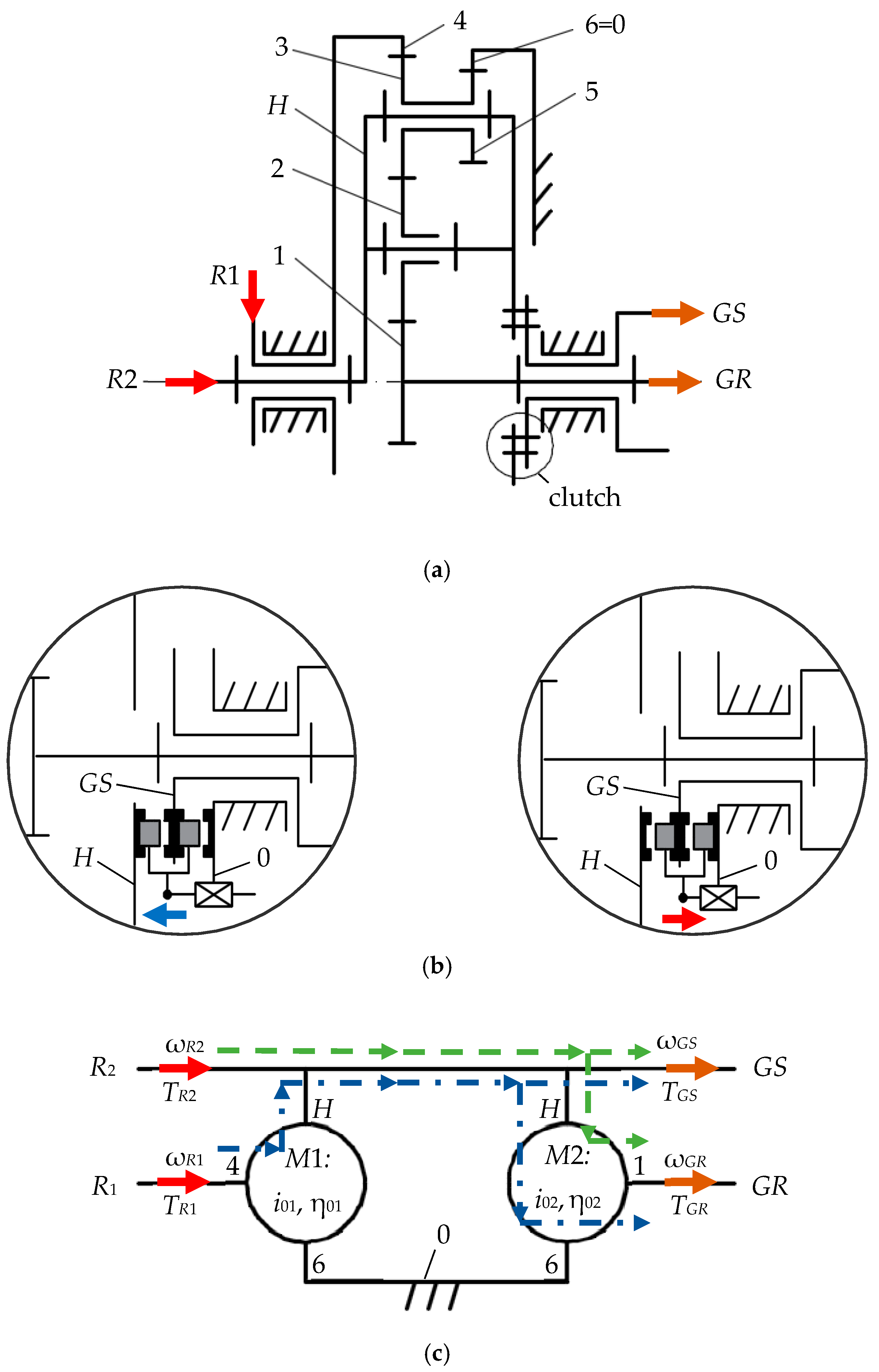
Variant V1: a system with two inputs and two outputs (L = 4), in which both input R1 and R2 and both output GR and GS are active. The input-output torque ratio kt > 0 is controlled by the blade-pitch angle of either or both rotors R1 and R2, while the clutch is set to connect carrier H to GS (see Figure 4b-left);
(2)
Variant V2: a system with two inputs and one output (L = 3), in which the output is connected to the electric-generator rotor GR, and stator GS is fixed by the clutch as shown in Figure 4b-right;
(3)
Variant V3: a system with one input and two outputs (L = 3), obtained from V1 by deactivating the secondary rotor R2 (kt = 0);
(4)
Variant V4: a system with one input and one output (L = 2), obtained from variant V1 by deactivating the secondary rotor R2 (kt = 0) and by connecting the electric-generator stator to the frame (see Figure 4b-right).
The two component planetary gear sets M1 and M2 are characterized by the interior kinematic ratios i01 and i02,
i 01 = i 46 H = i 43 H i 56 H = z 3 z 6 z 4 z 5 > 0 ;   i 02 = i 16 H = i 12 H i 23 H i 56 H = z 3 z 6 z 1 z 5 > 0
where i x y z is the angular speed ratio of body x and body y relative to body z.
For obvious reasons, the number of teeth z4 of ring gear 4 has to be bigger than the number of teeth z1 of sun gear 1 (i.e., z4 > z1), and according to Equation (22), inequality i02 > i01 should also hold true.
Efficiencies η01 and η02 are the internal efficiencies of mechanisms M1 and M2 associated to the respective planetary gear sets, when carrier H is fixed (see Equation (12), where η0 is the efficiency of one gear pair, and efficiencies η x y z correspond to the power being transmitted from member x to member y when z is held fixed, and where x, y can be either 1, 2, 3, 4, 5 and H, while z can be either 6 and H).
η 01 = η 43 H η 56 H = ( η 0 ) 2 ;   η 02 = η 12 H η 23 H η 56 H = ( η 0 ) 3
Coefficients a, b, c defined in Equation (13) can be calculated by applying a motion-inversion relative to planet carrier H [51]:
a = i 14 6 = ω 16 ω 46 = 1 i 02 1 i 01 ;   b = c = i H 4 6 = ω H 6 ω 46 = 1 1 i 01
In turn, torque-transmission functions are also linear equations according to Equation (25)
T R 1 = T R 1 ( G R ) + T R 1 ( R 2 ) + T R 1 ( G S ) ;   T R 1 ( G R ) = A T G R ;       T R 1 ( R 2 ) = B T R 2 ;     T R 1 ( G S ) = C T G S
where T R 1 ( x ) is the torque at the primary rotor shaft R1 obtained when all independent external torques are zero, except for Tx, and where coefficients A, B, C defined in Equation (14) are determined by applying the principle of superposition.
For example, torque T R 1 ( G R ) is obtained for TGR ≠ 0 (mechanical power is transmitted only to electric-generator rotor GR) and for TR2 = TGS = 0 (i.e., the secondary rotor R2 and the stator of the electric generator are idling).
Considering only the power flow from R1 to GR yields,
T R 1 ( G R ) ω 46 η 41 6 + T G R ω 16 = 0   = >   T R 1 ( G R ) = T G R a η 41 6
where,
η 41 6 = η 4 H 6 η H 1 6 ;   η 4 H 6 = 1 i 01 ¯ 1 i 01 ;   η H 1 6 = 1 i 02 1 i 02 ¯
and where i 01 ¯ and i 02 ¯ are torque ratios [51], defined as:
i 01 ¯ = i 01 η 01 x 1 ;   x 1 = s i g n   ( ω 4 H ω 46 ) = s i g n   ( i 01 i 01 1 )
i 02 ¯ = i 02 η 02 x 2 ;   x 2 = s i g n   ( ω 1 H ω 16 ) = s i g n   ( i 02 i 02 1 )
In the above equations, sign represents the sign function, and x1 = −1 for i01 < 1 and x1 = +1 for i01 > 1, x2 = +1 for i02 < 1 and x2 = −1 for i02 > 1, i01 ≠ 1, i02 ≠ 1. Because in a counter-rotating electric generator, the generator rotor must have a higher angular velocity than the stator i.e., |ωGR| > |ωGS|, then |a| > |c|, and as a result, i02 > 2 and x2 = −1.
From the condition that rotors R1 and R2 are counter-rotating, i.e., signR1 ωR2) = −1, and since b < 0, then i01 > 1 and x1 = +1 (see Equations (13) and (24)). It also implies that:
A = a η 41 6 = 1 i 02 ¯ 1 i 01 ¯ = 1 i 02 η 02 1 1 i 01 η 01
Coefficients B and C are determined similarly to coefficient A, by considering the power flow from R1 to R2 and from R1 to RS:
T R 1 ( R 2 ) ω 46 η 4 H 6 + T R 2 ω H 6 = 0   = >   T R 1 ( R 2 ) = T R 2 b η 4 H 6
T R 1 ( R S ) ω 46 η 4 H 6 + T R S ω H 6 = 0   = >   T R 1 ( R S ) = T R S c η 4 H 6
According to Equation (24), b = c which yields:
B = C = b η 4 H 6 = c η 4 H 6 = 1 1 i 01 ¯ = 1 1 i 01 η 01
By employing Equations (18)–(21), the efficiencies of the four variants of the 1-DOF planetary speed increaser are obtained.
For variant V1: two inputs and two outputs (L = 4):
η V 1 = i 02 i 02 ¯ 1 i 01 ¯ k t 1 i 01 k t = η 02 1 i 01 η 01 k t 1 i 01 k t
For variant V2: two inputs and one output (L = 3, ω G S = 0 ):
η V 2 = 1 i 02 1 i 02 η 02 1 1 i 01 η 01 k t 1 i 01 k t .
For variant V3: one input and two outputs (L = 3, k t = 0 ):
η V 3 = η 02 1 i 01 η 01 1 i 01
For variant V4: one input and one output (L = 2, ω G S = 0 , k t = 0 ):
η V 4 = 1 i 02 1 i 02 η 02 1 1 i 01 η 01 1 i 01

5. Numerical Simulations and Discussions

Four independent parameters, i.e., i01, i02, kt and η0 occur in the efficiency Equations (34)–(37) of the planetary speed increaser variants V1, V2, V3 and V4. The effects of these parameters upon overall efficiency and kinematic ratios of the respective speed increasers have been studied using bivariate plots as explained in [55,56] (see Figure 6, Figure 7, Figure 8, Figure 9 and Figure 10; note that in some of these plots the z-axis has been reversed for clarity). The value ranges of these four parameters have been considered as follows: the kinematic ratio of the speed increaser iaG = ωGR1 ≥ 3, input torque ratio kt < 2 and efficiency of a typical pair of gears η0 > 0.94 [57].
According to Equation (34), the efficiency of a speed increasers with two counter-rotating wind or water rotors and counter-rotating electric generator (variant V1) depends on i01, kt and η0, and it is not influenced by the interior kinematic ratio i02. As the plot in Figure 6 shows, the efficiency ηV1 of the speed increaser is influenced the most by the efficiency η0 of its constituent gear pairs, resulting in more than 12% increase, for only 4% improvement in η0 i.e., from 94% to 98%. Consequently, care should be given to the manufacturing quality of the individual gears. Also, what is visible in Figure 7 is a rapid decrease of ηV1 with a reduction of parameters i01 and kt, most noticeable for i01 < 1.75 and kt < 0.75. From Figure 10c it additionally becomes apparent that for 1 < i01 < 2, high values of the amplification ratio iaG are obtained. During the operation of a power generating system equipped with such a transmission, torque ratio kt will be adjusted via the pitch angles of the wind or water rotors. In the design stage, the anticipated range of kt should be correlated with interior ratio i01 and gear-pair efficiency η0 to achieve best speed increaser efficiency and a high amplification ratio iaG.
In case of variant V2 of gear increasers (which is the same as variant V1 but with a locked stator, i.e., ω G S = 0 ) Equation (35) indicates that the efficiency ηV2 of the increaser depends on all four parameters i01, i02, kt and η0. Assuming that each gear-pair of the transmission has the same efficiency η0 and equal to 0.965, according to the plot in Figure 7, ηV2 is influenced manly by the interior kinematic ratio i01 and by the torque ratio kt, and less by the interior ratio i02. As i02 increases and for i01 and kt assumed constant, a slight increase of ηV2 is observed. Likewise, efficiency ηV2 increases for kt < 1, and decreases slightly for kt > 1 as i01 increases. For kt = 1, efficiency ηV2 no longer depends on i01, which may be interesting when large kinematic amplification ratios iaG are desired. Same as for variant V1, an increase of the torque ratio kt is accompanied by an increase in efficiency ηV2. The increase of ηV2 with kt is more significant for small values of i01 than is for larger values of i01.
The efficiency of gear transmission variant V3 with one input R1 and two counter-rotating outputs GR and GS, depends only on i01 and η0 (see Equation (36)). The internal gear ratio i01 does not affect the efficiency ηV3 of the increaser and kt = 0. The 3D plot in Figure 8 shows, for i01 held constant, a linear correlation of efficiency ηV3 with η0. Also apparent is a rapid drop of efficiency ηV3 with i01, particularly for i01 < 1.75.
Variant V4 of gear increaser is characterized by kt = 0 (there is only one input i.e., R1) and by ω G S = 0 (the generator has a fixed stator). According to Equation (37) its efficiency ηV4 depends on parameters i01, i02 and η0. Higher values of the efficiency ηV4 are obtained for larger values of these three parameters, of which η0 has the most effect, Figure 9. Internal kinematic ratio i02 has a smaller effect, however, a rapid drop in ηV4 is observed for i01 approaching 1.
Based on the same plots in Figure 6, Figure 7, Figure 8 and Figure 9, the following additional conclusions can be drawn:
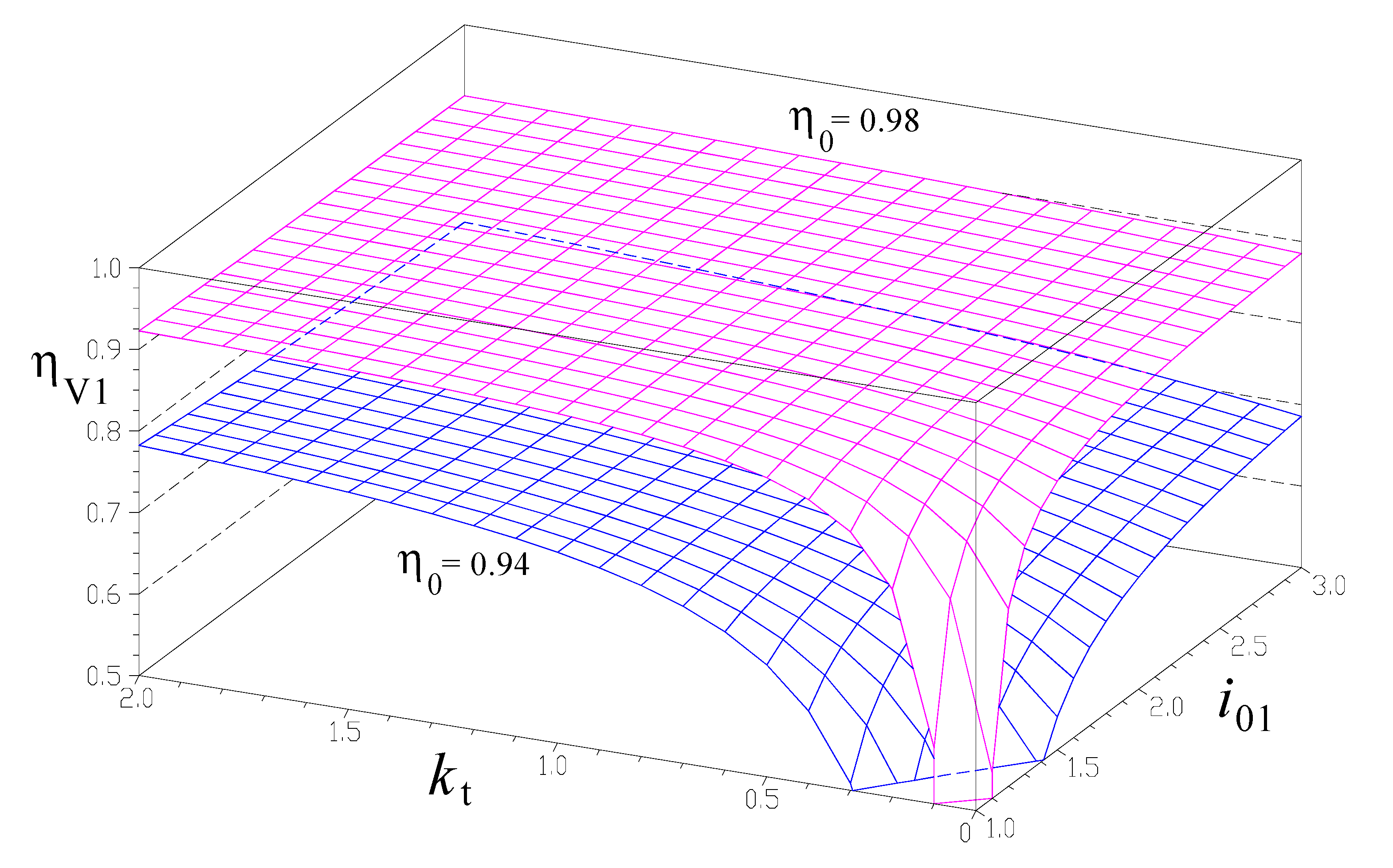
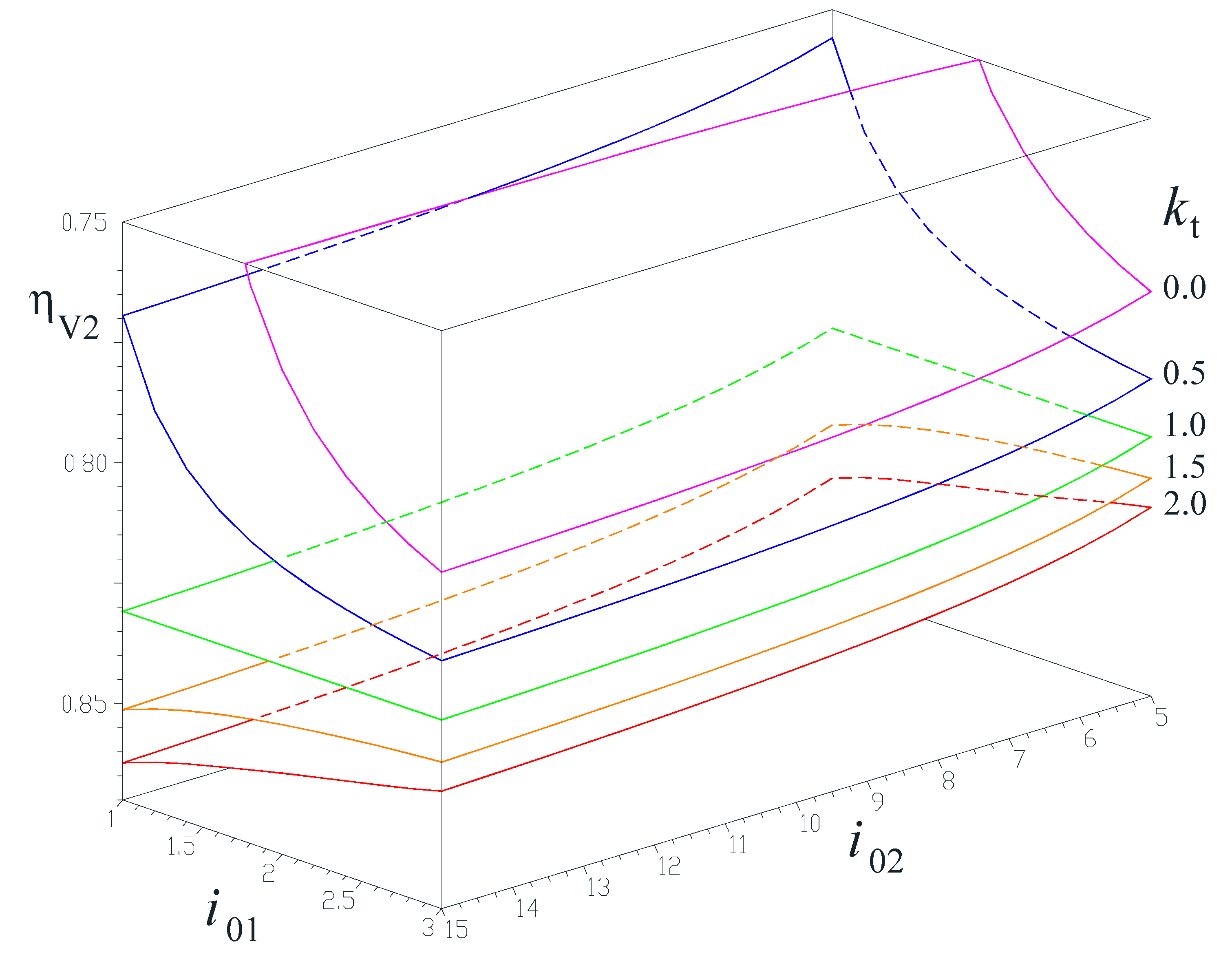
Efficiencies ηV1 and ηV2 increase as the input torque ratio kt increases. This is explicable by the relative increase of the power from the secondary wind or water rotor R2. It is worth mentioning that the power flow from R1 passes entirely through mechanism M1 and then through part of mechanism M2, while the power flow generated by R2 passes only partially through M2 and the rest is transmitted directly to the generator stator GS;
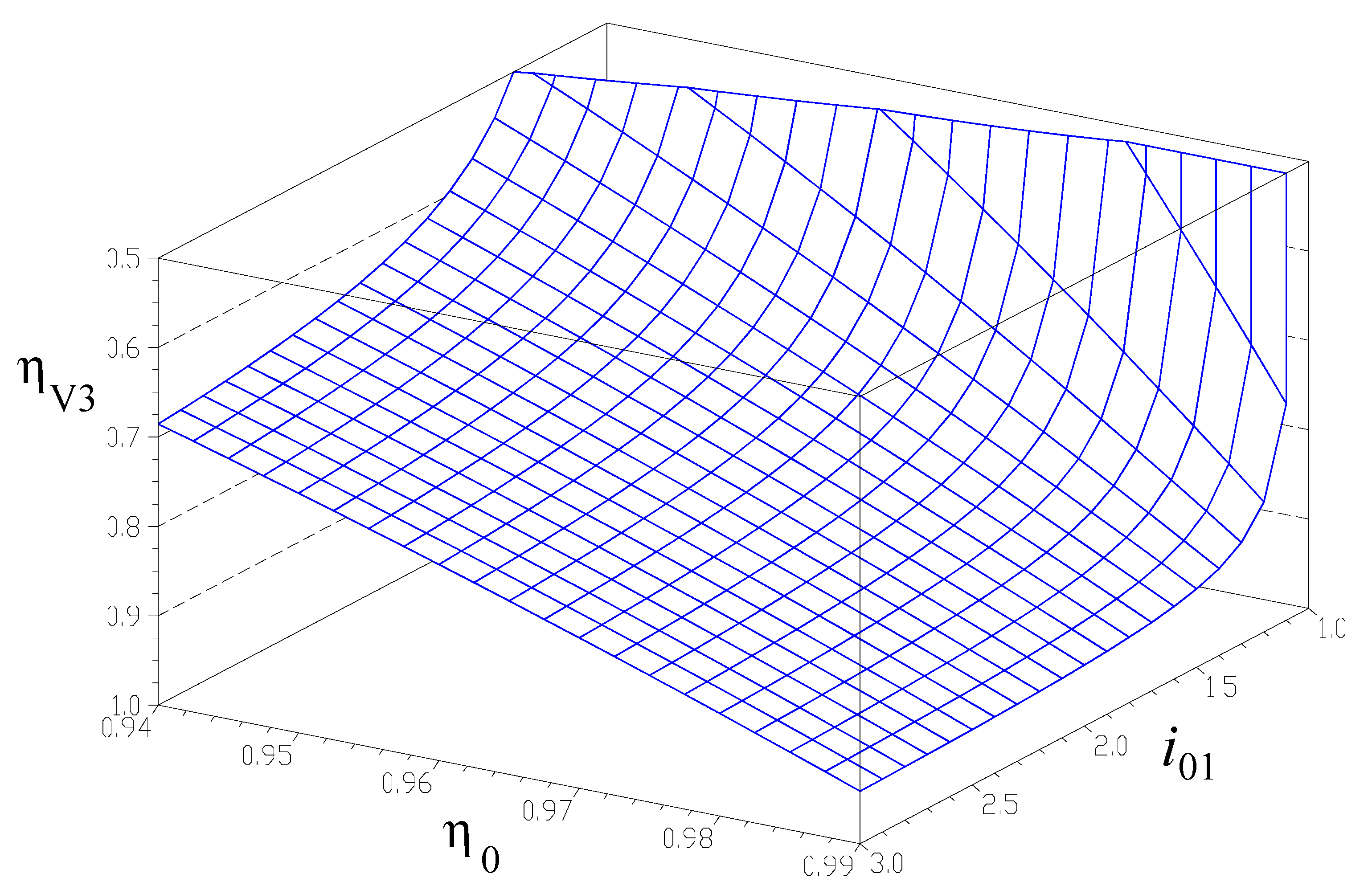
The interior kinematic ratio i01 influences strongly the speed-increaser efficiency in all four variants as kt approaching 0, particularly if 1 < i01 < 1.75. Furthermore, the mechanism locks (i.e., efficiency becomes negative) for i01 approaching 1;
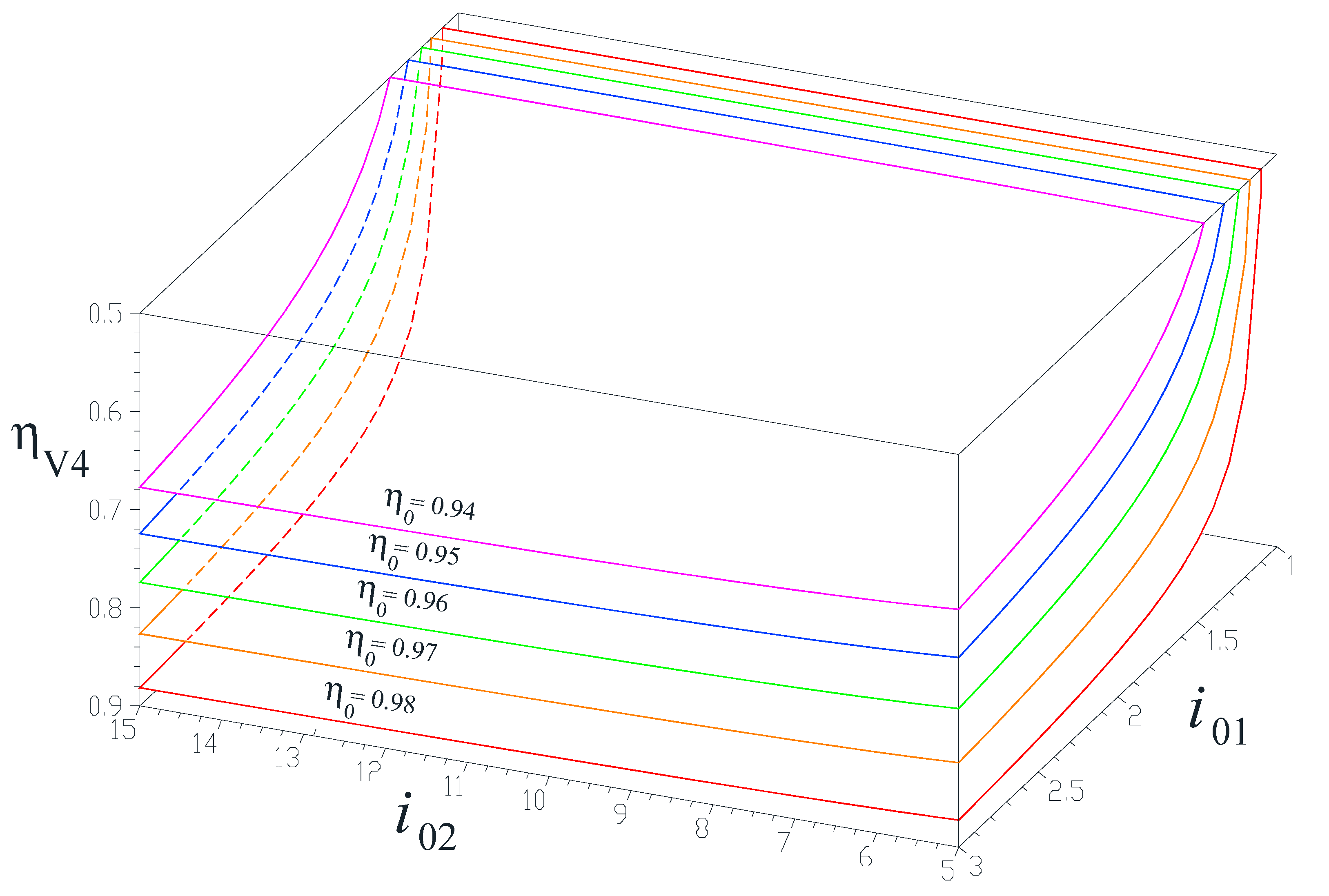
The interior kinematic ratio i02 does not occur in the efficiency Equations (34) and (36) for the speed increaser variants V1 and V3 with counter-rotating electric generator. Instead, efficiencies ηV2 and ηV4 (the cases with electric generator with a fixed stator) have markedly lower values for small values of parameter i02, but increase with the increase of i02;
The quality of the component gears and therefore the individual gear pair efficiencies η0, have a major influence upon the efficiency of the speed increaser, regardless of variant V1 to V4. Therefore, it is recommended that good quality gear pairs are used, in order to minimize losses and maximize the efficiency in transmitting mechanical power from wind or water rotors to the electric generator.
As a general conclusion, Figure 6, Figure 7, Figure 8 and Figure 9 confirm that split-power transmissions have higher efficiencies than serial transmission. Overall, the best efficiencies are provided by variant V1, which combines the split input power (Figure 2c) with the split output power (Figure 2b). The second most efficient is variant V2 with two inputs and one output (Figure 2c), followed by variant V3 with a single rotor and counter-rotating electric generator (Figure 2b). The least performing variant is V4 with serial transmission of mechanical power (Figure 2a). Thus, the efficiency of hydro/tidal/wind systems can be increased by adopting either a split-input power transmissions, a split-output power transmissions, or a transmissions with power split both at input and at output.
The interior kinematic ratios i01 and i02 of the component mechanisms M1 and M2, directly influence the transmission of input angular speed ωR1 to the electric generator, and implicitly, the relative speed ωG between the generator rotor and stator. The plots in Figure 10, depicted for variant V1 with two inputs and two outputs, indicate that the amplification ratio iaG = ωGR1 increases with the decrease of i01 and with the increase of i02. High kinematic ratios iaG can be obtained at reduced internal ratios i01 (e.g., iaG = 50 for i01 = 1.2 and i02 = 10) and/or in combination with high values of internal ratio i02 (e.g., iaG = 30 for i01 = 1.5 and i02 = 15).

6. Conclusions

This paper presented a generalized model of efficiency calculation of 1-DOF speed increasers applicable to hydro and wind energy conversion systems with two gear mechanisms in parallel. Possible operating modes involve one input or two counter-rotating inputs, and with a single or two generator outputs. The inputs are provided by two counter-rotating wind or water rotors, while the outputs are linked to the counter-rotating rotor and the stator of an electric generator.
It was found that the in-parallel or split-power transmissions have higher efficiency compared to the serial transmissions. The in-parallel power transmission can be achieved, either by using two counter-rotating wind or water rotors, or by employing an electric generator with counter-rotating rotor and stator. As a result, counter-rotating systems have higher efficiencies than conventional single input, single output systems.
For the general case of a speed increaser with two inputs and two outputs, an efficiency analysis has been performed where transmissions with only two inputs and one output; one input and two outputs, and with one input and one output result as particular cases. This approach has then been applied to a novel planetary gear speed increaser, which can operate in all four possible combinations using a built-in two-way clutch, and by adjusting the pitch angle of the wind or water rotors.
The results reveal that the speed-increasers with two inputs and two outputs have higher efficiency. The results presented in this paper offer design engineers a useful approach for the analysis and synthesis of high-performance wind/tidal/hydro electrical systems.

Author Contributions

Conceptualization, M.N., R.S. and C.J.; methodology, M.N., R.S., C.J., and P.A.S.; software, M.N., R.S. and P.A.S.; validation, M.N., R.S., C.J. and P.A.S.; formal analysis, M.N., R.S., and P.A.S.; investigation, M.N., R.S., C.J., P.A.S.; resources, M.N., R.S., C.J., and P.A.S.; data curation, M.N., R.S., C.J., and P.A.S.; writing—original draft preparation, M.N., R.S. and C.J.; writing—review and editing, M.N. and P.A.S.; visualization, M.N., R.S., C.J., and P.A.S.; supervision, M.N. All authors contributed equally to editing and revising of this review. All authors have read and agreed to the published version of the manuscript.

Funding

This research received no external funding.

Acknowledgments

The comments, suggestions and recommendations for future research by the anonymous reviewers are gratefully acknowledged.

Conflicts of Interest

The authors declare no conflict of interest.

Nomenclature

CRWTCounter-Rotating Wind Turbine
SISpeed increaser
RRotor
R1Primary rotor
R2Secondary rotor
PPower
ωAngular speed
TTorque
ktRatio of the input torques
zGear teeth number
HSatellite carrier
a, b, cKinematic coefficients
A, B, CStatic coefficients
DOFDegree of Freedom
M1, M2Mechanism 1 or 2
LTotal number of inputs and outputs
GStandard electric generator
GRElectric generator rotor
GSElectric generator stator
iKinematic ratio
i01,2Interior kinematic ratio of the mechanism M1,2
iaAmplification kinematic ratio
ηEfficiency of the speed increaser
η01,2Interior efficiency of the mechanism M1,2
η0Efficiency of a gear pair

References

  1. Dincer, I. (Ed.) Comprehensive Energy Systems; Elsevier Science & Technology: Amsterdam, The Netherlands, 2018; ISBN 978-0-12-809597-3. [Google Scholar]
  2. World Energy Resources Charting the Upsurge in Hydropower Development. 2015. Available online: www.worldenergy.org/publications/entry/charting-the-upsurge-in-hydropower-development-2015 (accessed on 19 August 2020).
  3. Jaliu, C.; Diaconescu, D.V.; Neagoe, M.; Saulescu, R. The eco-impact of small hydro implementation. Environ. Eng. Manag. J. 2009, 8, 837–841. [Google Scholar] [CrossRef]
  4. Hydro Power. Available online: https://ec.europa.eu/research/energy/index.cfm?pg=area&areaname=renewable_hydro (accessed on 19 August 2020).
  5. Visa, I.; Jaliu, C.; Duta, A.; Neagoe, M.; Comsit, M.; Moldovan, M.; Ciobanu, D.; Burduhos, B.; Saulescu, R. The Role of Mechanisms in Sustainable Energy Systems; Transilvania University Press: Brasov, Romania, 2015; ISBN 978-606-19-0571-3. [Google Scholar]
  6. Manwell, J.F.; McGowan, J.G.; Rogers, A.L. Wind Energy Explained: Theory, Design and Application; Wiley: Hoboken, NJ, USA, 2009. [Google Scholar]
  7. Pelikan, B.; Armand, F.; Schleiss, A.; Bollaert, B.; Manso, P.; Bard, J.; O’Nians, J.; Denis, V.; Corbet, J.-P.; Soderberg, C.; et al. Guide on How to Develop a Small Hydropower Plant; European Small Hidro-Power Association (ESHA): Brussels, Belgium, 2004. [Google Scholar]
  8. Shin, C. Multi-Unit Rotor Blade System Integrated Wind Turbine. U.S. Patent No. 5876181, 2 March 1999. [Google Scholar]
  9. Appa, K. Energy Innovations Small Grant (EISG) Program (Counter Rotating Wind Turbine System); EISG Final Report; EISG: Shores, CA, USA, 2002; Available online: https://www.eai.in/ref/invent/upload/00-09%2520FAR%2520Appendix%2520A.pdf (accessed on 19 August 2020).
  10. Jung, S.; No, T.; Ryu, K. Aerodynamic performance prediction of a 30 kW counter-rotating wind turbine system. Renew. Energy 2005, 30, 631–644. [Google Scholar] [CrossRef]
  11. Wacinski, A. Drive Device for a Windmill Provided with Two Counter–Rotative Propellers. U.S. Patent 7,384,239, 10 June 2008. [Google Scholar]
  12. Brander, M. Bi-Directional Wind Turbine. U.S. Patent Application 2008/0197639 A1, 21 August 2008. [Google Scholar]
  13. Climescu, O.; Saulescu, R.; Jaliu, C. Specific features of a counter-rotating transmission for renewable energy systems. Environ. Eng. Manag. J. 2011, 10, 1105–1113. [Google Scholar] [CrossRef]
  14. Hwang, B.; Lee, S.; Lee, S. Optimization of a counter-rotating wind turbine using the blade element and momentum theory. J. Renew. Sustain. Energy 2013, 5, 052013. [Google Scholar] [CrossRef] [Green Version]
  15. Didane, D.H.; Rosly, N.; Zulkafli, M.F.; Shamsudin, S.S. Performance evaluation of a novel vertical axis wind turbine with coaxial contra-rotating concept. Renew. Energy 2015, 115, 353–361. [Google Scholar] [CrossRef]
  16. Oprina, G.; Chihaia, R.A.; El-Leathey, L.A.; Nicolaie, S.; Babutanu, C.A.; Voina, A. A review on counter-rotating wind turbines development. J. Sustain. Energy 2016, 7, 91–98. [Google Scholar]
  17. Vasel-Be-Hagh, A.; Archer, C. Wind farms with counter-rotating wind turbines. Sustain. Energy Technol. Assess. 2017, 24, 19–30. [Google Scholar] [CrossRef]
  18. West, R. Wind Turbine System. U.S. Patent 10,316,820B2, 11 June 2019. [Google Scholar]
  19. Didane, D.H.; Rosly, N.; Zulkafli, M.F.; Shamsudin, S.S. Numerical investigation of a novel contra-rotating vertical axis wind turbine. Sustain. Energy Technol. Assess. 2019, 31, 43–53. [Google Scholar] [CrossRef]
  20. Jaliu, C.; Saulescu, R.; Diaconescu, D.V.; Neagoe, M. Conceptual design of a chain speed increaser for small hydropower stations. In Proceedings of the ASME 2009 International Design Engineering Technical Conferences & Computers and Information in Engineering Conference IDETC/CIE 2009, San Diego, CA, USA, 30 August–2 September 2009; ISBN 978-0-7918-3856-3. [Google Scholar]
  21. Booker, J.D.; Mellor, P.H.; Wrobel, R.; Drury, D. A compact, high efficiency contra-rotating generator suitable for wind turbines in the urban environment. Renew. Energy 2010, 35, 2027–2033. [Google Scholar] [CrossRef]
  22. Erturk, E.; Sivrioglu, S.; Bolat, F.C. Analysis Model of a Small Scale Counter-Rotating Dual Rotor Wind Turbine with Double Rotational Generator Armature. Int. J. Renew. Energy Res. 2018, 8, 1849–1858. [Google Scholar]
  23. Hall, J.F.; Mecklenborg, C.A.; Chen, D.; Pratap, S.B. Wind energy conversion with a variable-ratio gearbox: Design and analysis. Renew. Energy 2011, 36, 1075–1080. [Google Scholar] [CrossRef]
  24. Jelaska, D.; Podrug, S.; Perkusic, M. A novel hybrid transmission for variable speed wind turbines. Renew. Energy 2015, 83, 78–84. [Google Scholar] [CrossRef]
  25. Saulescu, R.; Neagoe, M.; Munteanu, O.; Cretescu, N. Performance Analysis of a Novel Planetary Speed Increaser Used in Single-Rotor Wind Turbines with Counter-Rotating Electric Generator; Materials Science and Engineering—IOP Conference Series: Materials Science and Engineering; IOP Publishing Ltd.: Bristol, UK, 2016. [Google Scholar] [CrossRef]
  26. Neagoe, M.; Saulescu, R.; Jaliu, C.; Cretescu, N. Novel Speed increaser used in counter-rotating wind turbines. In New Advances in Mechanisms, Mechanical Transmissions and Robotics, Mechanisms and Machine Science 46; Springer: Berlin, Germany, 2017; pp. 143–151. [Google Scholar] [CrossRef]
  27. Jaliu, C.; Diaconescu, D.V.; Neagoe, M.; Saulescu, R. Dynamic features of speed increasers from mechatronic wind and hydro systems. Part I. Structure Kinematics. In Proceedings of the Second European Conference on Mechanism Science EUCOMES 08, Casino, Italy, 17–20 September 2008; Springer: Dordrecht, The Netherlands, 2008; pp. 355–363, ISBN 987-1-4020-8914-5. [Google Scholar]
  28. Jaliu, C.; Diaconescu, D.V.; Neagoe, M.; Saulescu, R. Dynamic features of speed increasers from mechatronic wind and hydro systems. Part II. Dynamic aspects. In Proceedings of the Second European Conference on Mechanism Science EUCOMES 08, Casino, Italy, 17–20 September 2008; Springer: Dordrecht, The Netherlands, 2008; pp. 365–373, ISBN 987-1-4020-8914-5. [Google Scholar]
  29. Bevington, C.M.; Bywaters, G.L.; Coleman, C.C.; Costin, D.P.; Danforth, W.L.; Lynch, J.A.; Rolland, R.H. Wind Turbine Having a Direct-Drive Drivetrain. U.S. Patent 7431567B1, 7 October 2008. [Google Scholar]
  30. Marjanovic, N.; Isailovic, B.; Marjanovic, V.; Milojevic, Z.; Blagojevic, M.; Bojic, M. A practical approach to the optimization of gear trains with spur gears. Mech. Mach. Theory 2012, 53, 1–16. [Google Scholar] [CrossRef]
  31. Qiu, J.; Liu, B.; Dong, H.; Wang, D. Type Synthesis of Gear-box in Wind Turbine. Procedia Comput. Sci. C 2017, 109, 809–816. [Google Scholar] [CrossRef]
  32. Climescu, O.; Jaliu, C.; Saulescu, R. Comparative Analysis of Horizontal Small Scale Wind Turbines for a Specific Application. In Proceedings of the 14th IFToMM World Congress, Taipei, Taiwan, 25–30 October 2015. [Google Scholar] [CrossRef]
  33. Saulescu, R.; Neagoe, M.; Jaliu, C. Improving the Energy Performance of Wind Turbines Implemented in the Built Environment Using Counter-Rotating Planetary Transmissions; Materials Science and Engineering—IOP Conference Series: Materials Science and Engineering; IOP Publishing Ltd.: Bristol, UK, 2016. [Google Scholar] [CrossRef]
  34. Saulescu, R.; Jaliu, C.; Neagoe, M. Structural and Kinematic Features of a 2 DOF Speed Increaser for Renewable Energy Systems. Appl. Mech. Mater. 2016, 823, 367–372. [Google Scholar] [CrossRef]
  35. Saulescu, R.; Neagoe, M.; Jaliu, C.; Munteanu, O. Comparative analysis of two wind turbines with planetary speed increaser in steady-state. Appl. Mech. Mater. 2016, 823, 355–360. [Google Scholar] [CrossRef]
  36. Saulescu, R.; Jaliu, C.; Munteanu, O.; Climescu, O. Planetary Gear for Counter-rotating Wind Turbines. Appl. Mech. Mater. 2014, 658, 135–140. [Google Scholar] [CrossRef]
  37. Saulescu, R.; Jaliu, C.; Climescu, O.; Diaconescu, D. On the use of 2 DOF planetary gears as “speed increaser” in small hydros and wind turbines. In Proceedings of the ASME International Design Engineering Technical Conferences & Computers and Information in Engineering Conference IDETC/CIE 2011, Washington, DC, USA, 25–31 August 2011. [Google Scholar]
  38. Herzog, R.; Schaffarczyk, A.P.; Wacinski, A.; Zürcher, O. Performance and stability of a counter–rotating windmill using a planetary gearing: Measurements and Simulation. In Proceedings of the European Wind Energy Conference & Exhibition, Warsaw, Poland, 20–23 April 2010. [Google Scholar]
  39. Neagoe, M.; Saulescu, R.; Jaliu, C. Design and Simulation of a 1 DOF Planetary Speed Increaser for Counter-Rotating Wind Turbines with Counter-Rotating Electric Generators. Energies 2019, 12, 1754. [Google Scholar] [CrossRef] [Green Version]
  40. Saulescu, R.; Neagoe, M.; Jaliu, C. Conceptual Synthesis of Speed Increasers for Wind Turbine Conversion Systems. Energies 2018, 11, 2257. [Google Scholar] [CrossRef] [Green Version]
  41. Sapre, R.; Murkute, H.; Agrawal, R. Comparison between single axis wind turbine and counter wind turbine—A case study. Glob. J. Eng. Appl. Sci. 2012, 2, 144–146. [Google Scholar]
  42. Lee, S.; Kim, H.; Lee, S. Analysis of aerodynamic characteristics on a counter-rotating wind turbine. Curr. Appl. Phys. 2010, 10, S339–S342. [Google Scholar] [CrossRef]
  43. Lee, S.; Kim, H.; Son, E.; Lee, S. Effects of design parameters on aerodynamic performance of a counter-rotating wind turbine. Renew. Energy 2012, 42, 140–144. [Google Scholar] [CrossRef]
  44. Farahani, E.M.; Hosseinzadeh, N.; Ektesabi, M. Comparison of fault-ride-through capability of dual and single-rotor wind turbines. Renew. Energy 2012, 48, 473–481. [Google Scholar] [CrossRef]
  45. No, T.S.; Kim, J.E.; Moon, J.H.; Kim, S.J. Modelling, control, and simulation of dual rotor wind turbine generator system. Renew. Energy 2009, 34, 2124–2132. [Google Scholar] [CrossRef]
  46. Kubo, K.; Hano, Y.; Mitarai, H.; Hirano, K.; Kanemoto, T.; Galal, A.M. Intelligent wind turbine unit with tandem rotors (discussion of prototype performances in field tests). Curr. Appl. Phys. 2010, 10, S326–S331. [Google Scholar] [CrossRef]
  47. Chantharasenawong, C.; Suwantragul, B.; Ruangwiset, A. Axial Momentum Theory for Turbines with Co-axial Counter Rotating Rotors. In Proceedings of the Commemorative International Conference of the Occasion of the 4th Cycle Anniversary of KMUTT Sustainable Development to Save the Earth: Technologies and Strategies Vision 2050: (SDSE2008), Bangkok, Thailand, 11–13 December 2008. [Google Scholar]
  48. Zhamalov, A.Z.; Obozov, A.D.; Kunelbaev, M.M.; Baikadamova, L.S. Capacity and Power Characteristics of Disk Generator with Counter-Rotation of Double-Rotor Wind Turbine. Middle-East J. Sci. Res. 2013, 15, 1655–1662. [Google Scholar] [CrossRef]
  49. Kanemoto, T.; Galal, A.M. Development of intelligent wind turbine generator with tandem wind rotors and double rotational armatures. JSME Int. J. Ser. B 2006, 49, 450–457. [Google Scholar] [CrossRef] [Green Version]
  50. Caiozza, J. Wind Driven Electric Generator Apparatus. U.S. Patent 7227276 B2, 5 June 2007. [Google Scholar]
  51. Miloiu, G.; Dudita, F.l.; Diaconescu, D. Modern Mechanical Transmissions; Tehnica: Bucharest, Romania, 1980. (In Romanian) [Google Scholar]
  52. Santoso, S.; Le, H.T. Fundamental time–domain wind turbine models for wind power studies. Renew. Energy 2007, 32, 2436–2452. [Google Scholar] [CrossRef]
  53. Hall, J.F.; Chen, D. Dynamic Optimization of Drivetrain Gear Ratio to Maximize Wind Turbine Power Generation—Part 1: System Model and Control Framework. J. Dyn. Syst. Meas Control 2012, 135, 011016. [Google Scholar] [CrossRef]
  54. Neagoe, M.; Saulescu, R.; Jaliu, C.; Munteanu, O. Reconfigurable Adjustable Planetary Speed Increaser for Wind Turbines and Adjustment Method. Romanian Patent Application No. A/00224, 24 March 2020. [Google Scholar]
  55. Simionescu, P.A.; Smith, M.R. Single-valued function representations in linkage mechanisms design. Mech. Mach. Theory 2000, 35, 1709–1726. [Google Scholar] [CrossRef]
  56. Simionescu, P.A. Contributions to the Optimum Synthesis of Linkage-Mechanisms with Applications. Ph.D. Thesis, Politehnica University of Bucharest, Bucharest, Romania, 1999. Available online: http://faculty.tamucc.edu/psimionescu/papers.html (accessed on 19 August 2020).
  57. Chen, T.H.; Tang, H.C. Meshing Efficiency Analysis of Straight Spur Gear Pair. Appl. Mech. Mater. 2015, 764–765, 314–318. [Google Scholar] [CrossRef]
Figure 1. Dual rotor; (a) wind turbine of Kowintech Co. Ltd.; and (b) tidal turbine of SIMEC Atlantis Energy (formerly Atlantis Resources Corp.).
Energies 13 04568 g001
Figure 2. Block diagrams of 1-DOF speed increasers with two 1-DOF mechanisms M1 and M2, having: (a) one rotor and one standard electric generator; (b) one rotor and counter-rotating electric generator; (c) two counter-rotating input rotors with standard electric generator. R, R1 and R2 are wind or water rotors, G and GR are the electric-generator rotor; GS is the electric generator stator; Tx is the torque transmitted and ωx is the angular velocity of shaft x; and i1 and i2 are the kinematic ratios and η1 and η2 are the efficiencies of constituent mechanisms M1 and M2.
Energies 13 04568 g002
Figure 3. Block diagram of 1-DOF speed increasers with two counter-rotating inputs and two counter-rotating outputs, obtained by connecting in parallel the planetary gear sets M1 and M2.
Energies 13 04568 g003
Figure 4. 1-DOF cylindrical-gear speed increaser in a generalized configuration with two inputs and two outputs: (a) structural diagram; (b) detail of the two-way clutch (left) in the HGS position and (right) in the GS ≡ 0 position; (c) block diagram showing the input-output power flow.
Energies 13 04568 g004
Figure 5. Structural and block diagrams of the 1-DOF speed increaser in Figure 4a with (a) two inputs and two outputs (variant V1); (b) two inputs and one output (variant V2); (c) one input and two outputs (variant V3) and (d) one input and one output (variant V4).
Energies 13 04568 g005
Figure 6. Efficiency of the 1-DOF speed increaser variant V1 (Figure 5a) as function of the interior kinematic ratio i01, torque ratio kt, and efficiency of each gear-pair η0 = 0.98.
Energies 13 04568 g006
Figure 7. Efficiency of the 1-DOF speed increaser variant V2 (Figure 5b), as functions of the interior kinematic ratios i01 and i02, for torque ratios kt = 0, 0.5, 1.0, 1.5 and 2.0, assuming η0 = 0.965.
Energies 13 04568 g007
Figure 8. Efficiency of the 1-DOF speed increaser variant V3 (Figure 5c), as function of the interior kinematic ratio i01 and η0.
Energies 13 04568 g008
Figure 9. Efficiency of the 1-DOF speed increaser variant V4 (Figure 5d) as functions of the interior kinematic ratios i01 and i02, for various gear-pair efficiencies η0 = 0.94, 0.95, 0.96, 0.97 and 0.98.
Energies 13 04568 g009
Figure 10. Variations of kinematic ratios (a) iaGR (from R1 to GR), (b) iaGS (from R1 to GS) and (c) iaG (from R1 to G in of counter-rotating electric generator) as functions of the interior kinematic ratios i01 and i02.
Energies 13 04568 g010

