Energy and Exergy Evaluations of a Combined Heat and Power System with a High Back-Pressure Turbine under Full Operating Conditions


Abstract
1. Introduction
2. System Description
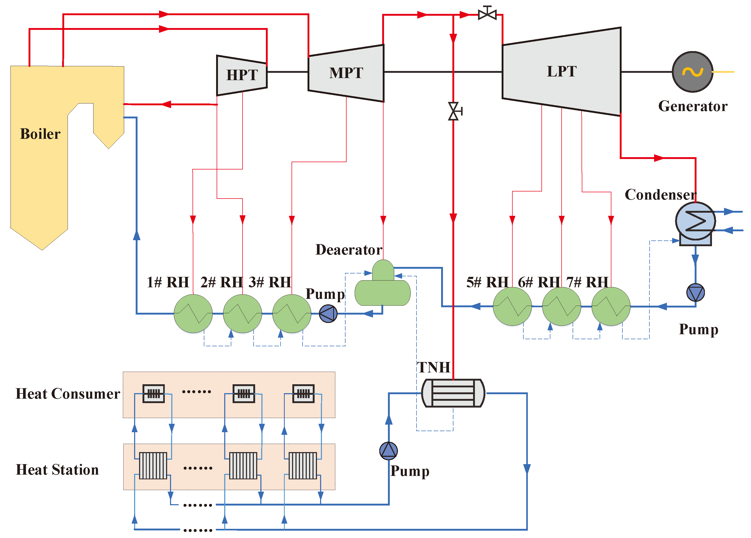
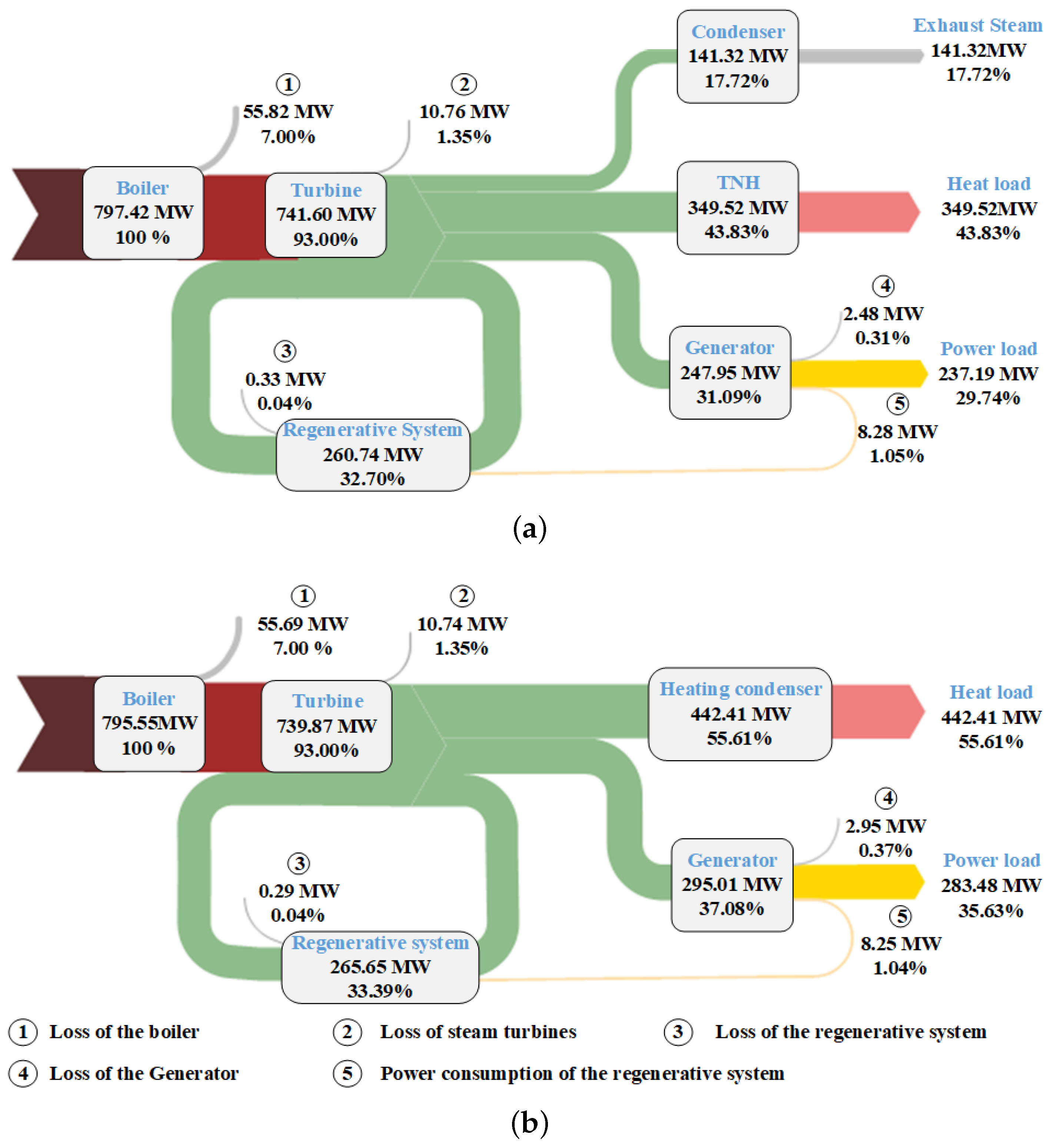
2.1. Traditional CHP System
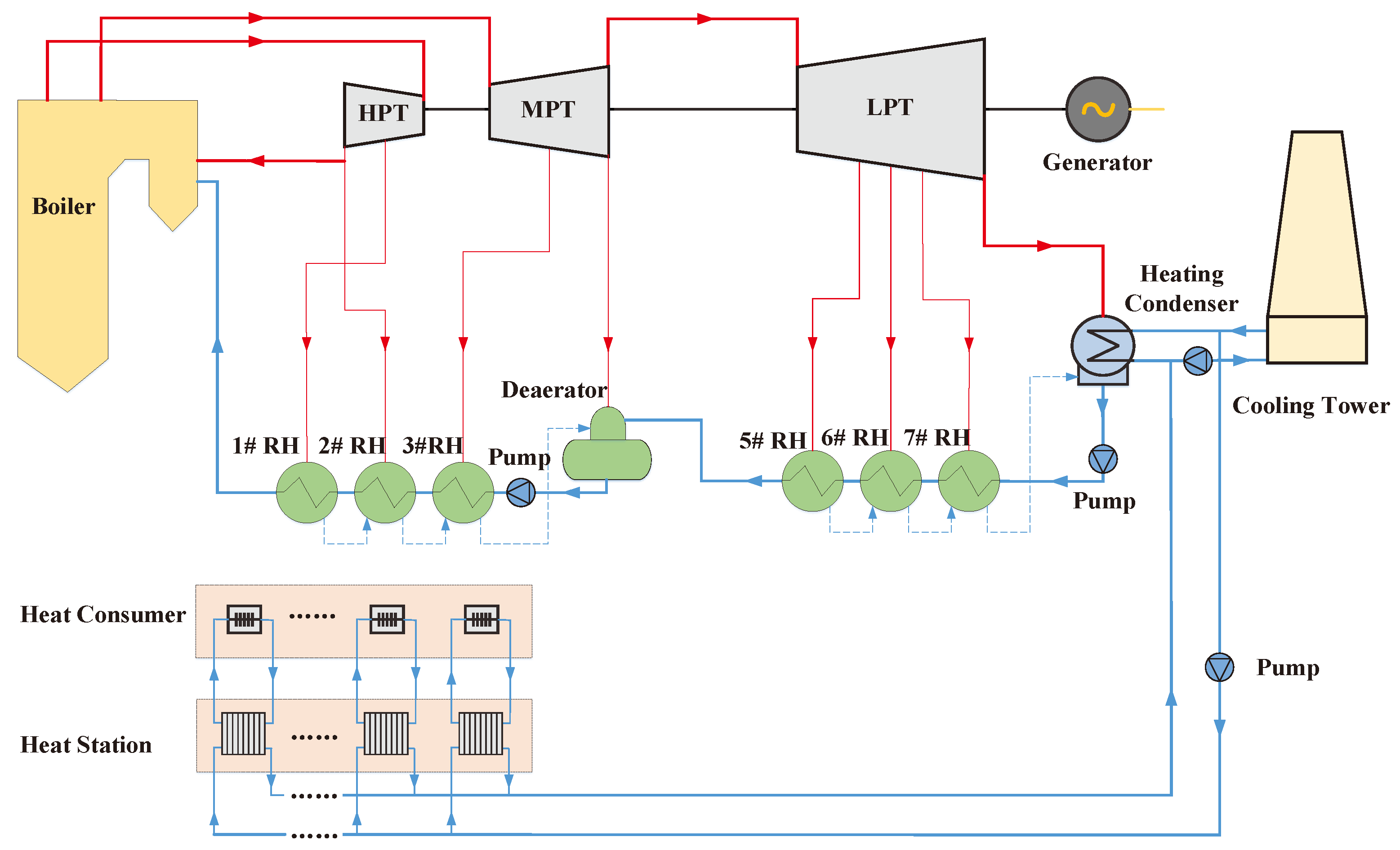
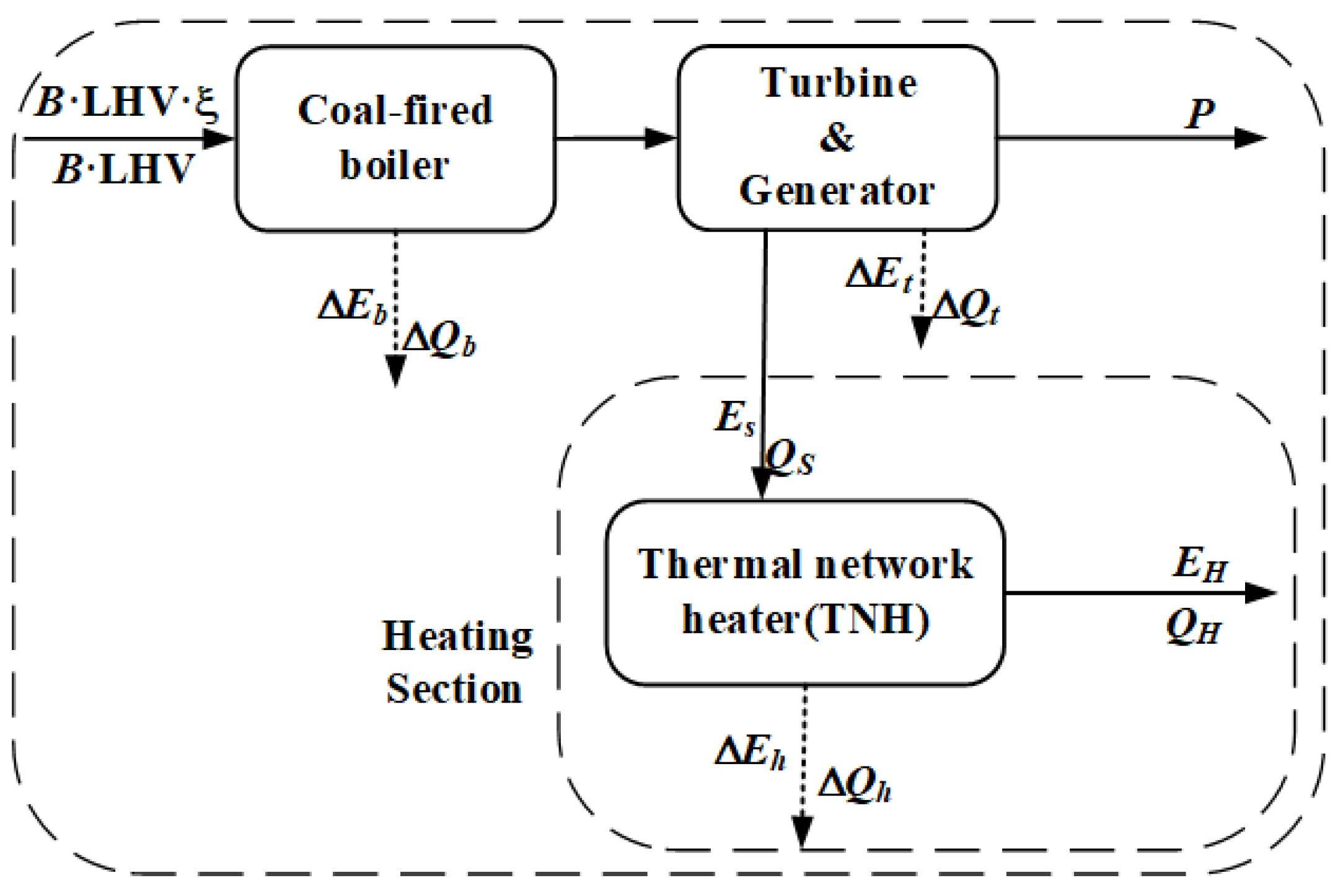
2.2. CHP System with a High Back-Pressure Turbine
3. Modeling and Evaluation Criterion
3.1. Modeling Method
3.2. Evaluation Criterion
3.2.1. Energy-Based Evaluation
3.2.2. Conventional Exergy-Based Evaluation
4. Results and Discussion
4.1. Traditional Energy-Based and Exergy-Based Evaluations
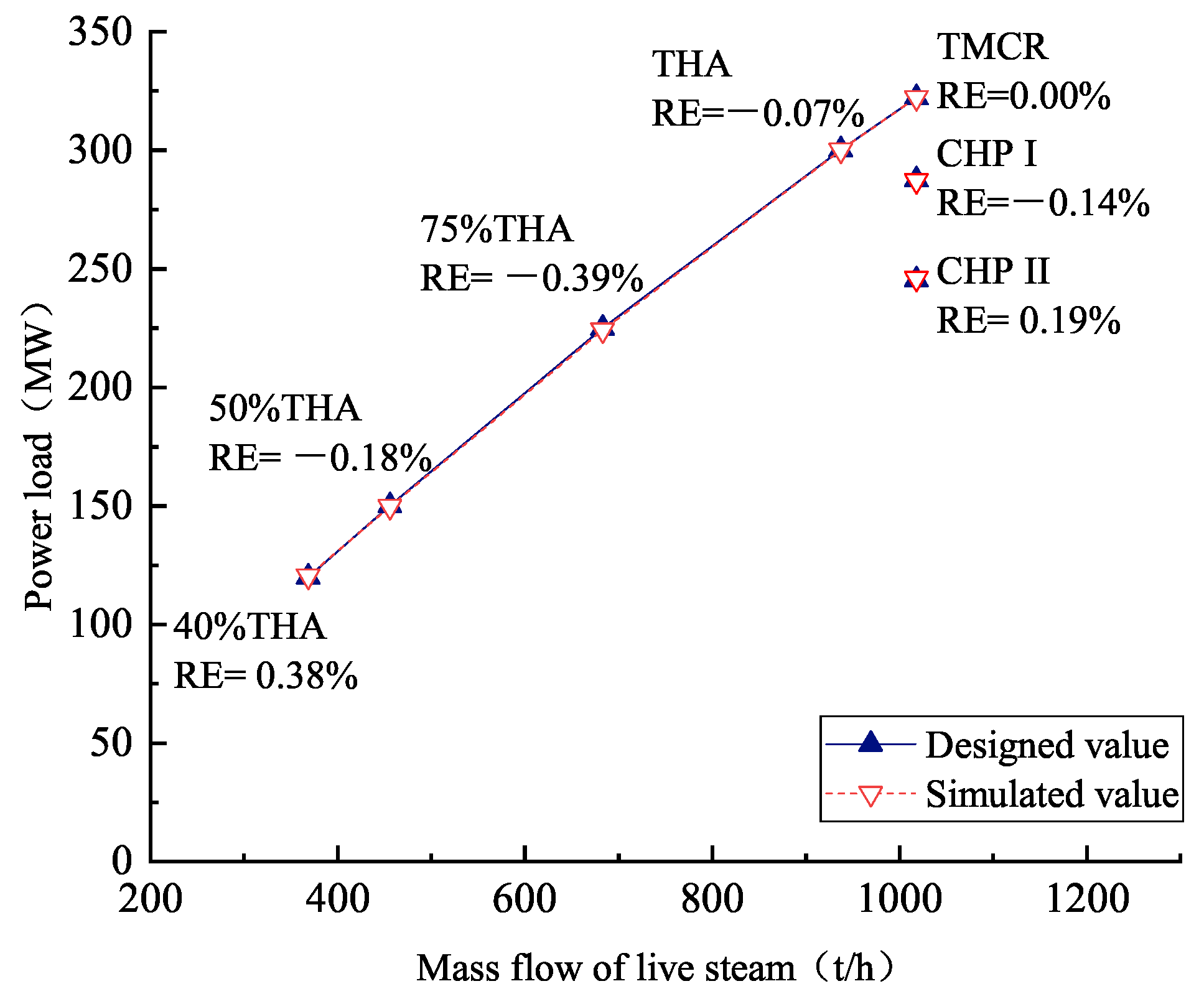
4.1.1. Thermodynamic Performance in Design Conditions
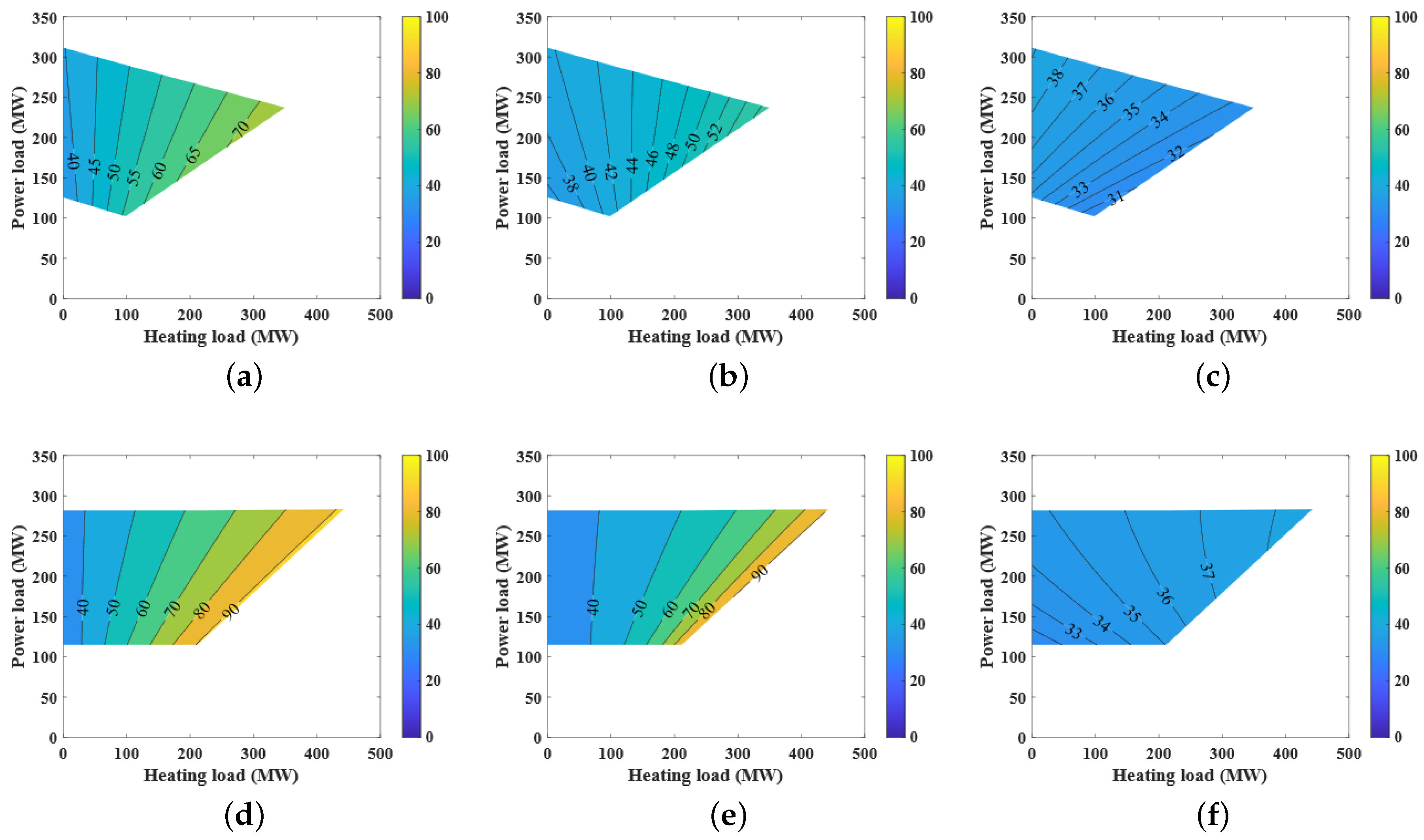
4.1.2. Efficiencies under the Off-Design Conditions
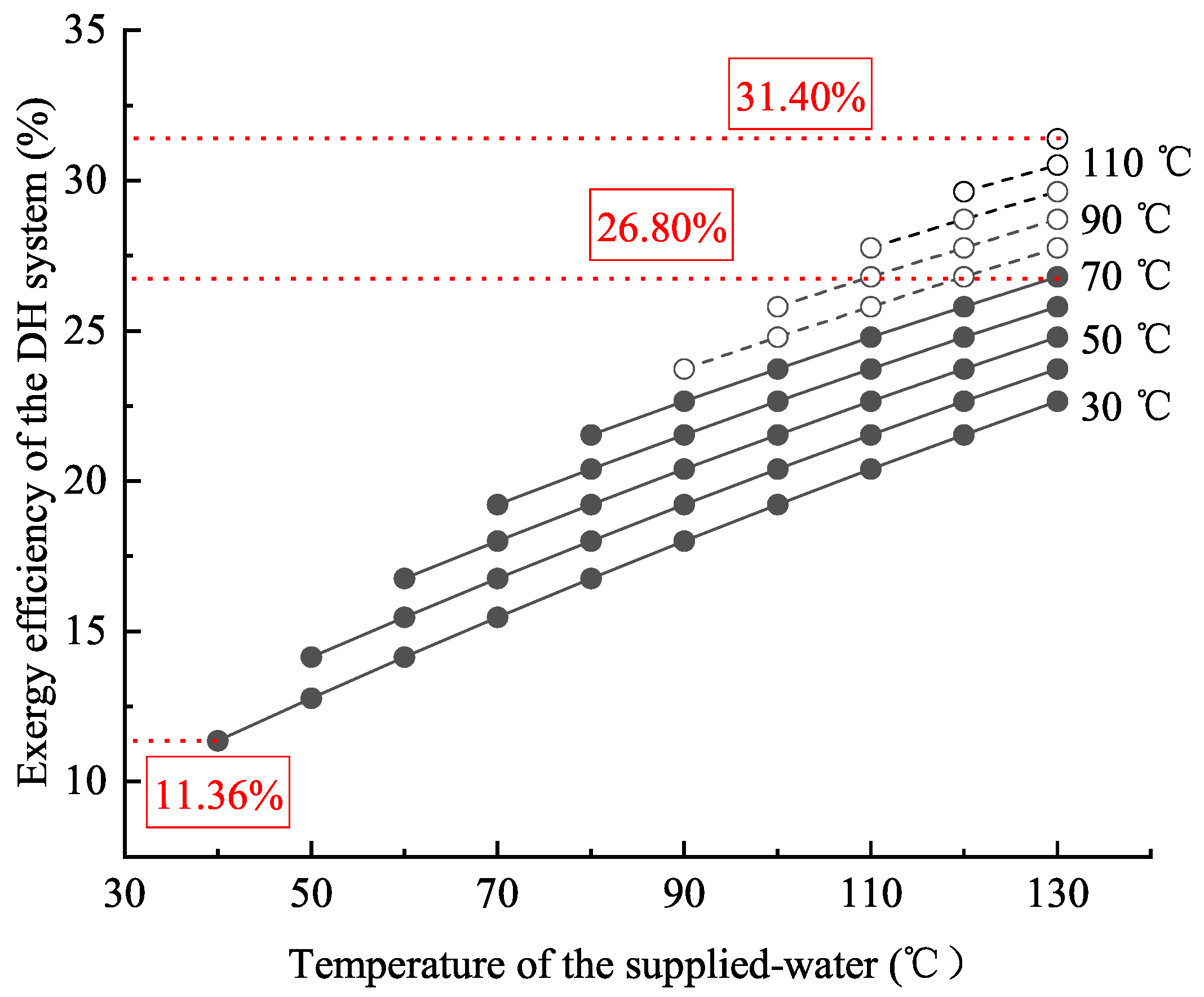
4.1.3. Exergy Analysis with Different Cold-End Temperatures
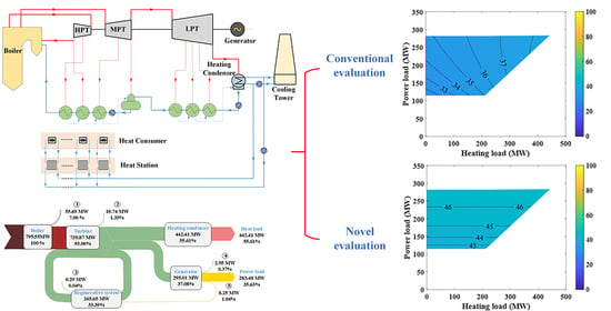
4.2. Novel Exergy-Based Evaluation
4.2.1. Limitations of the Traditional Evaluations
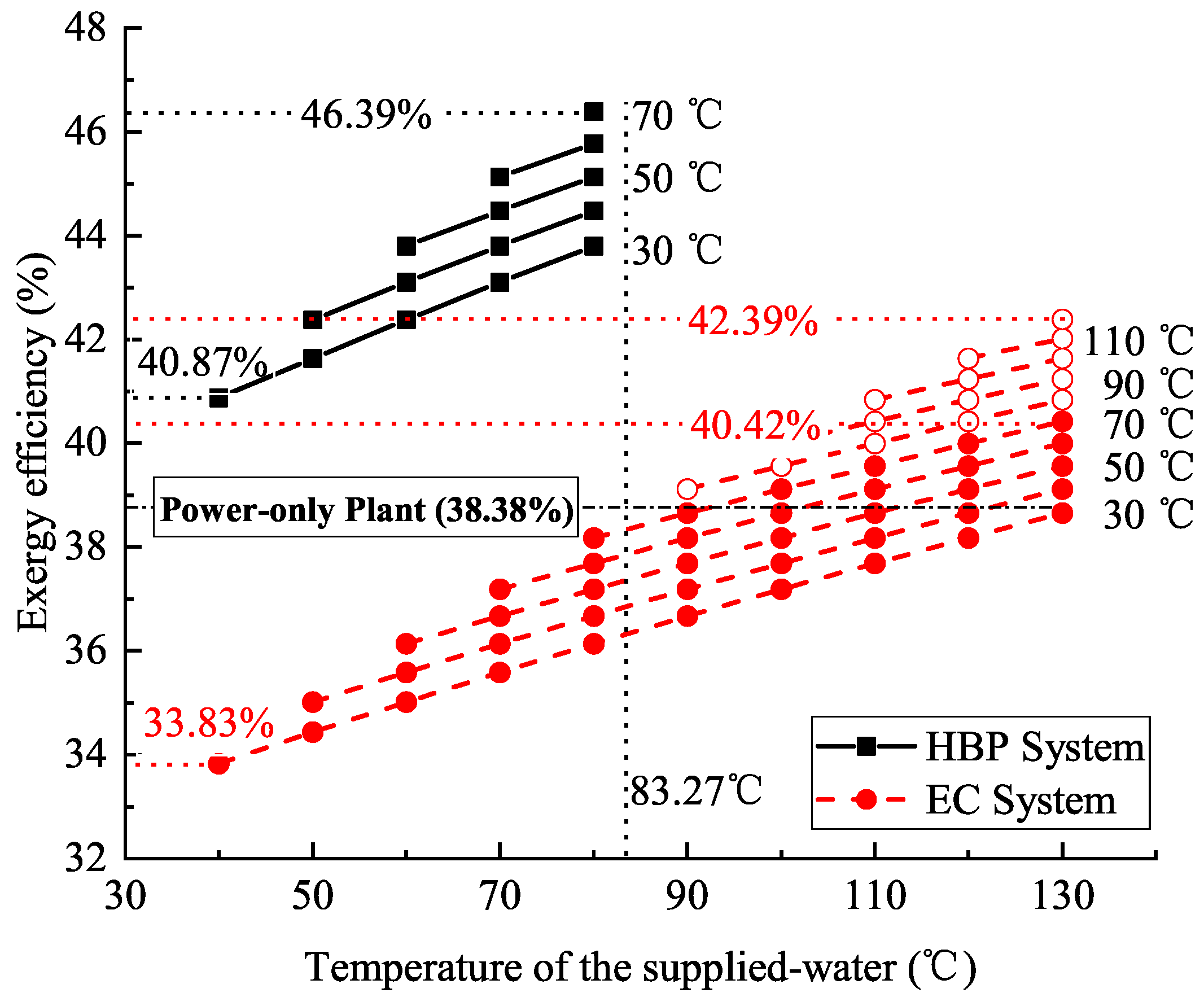
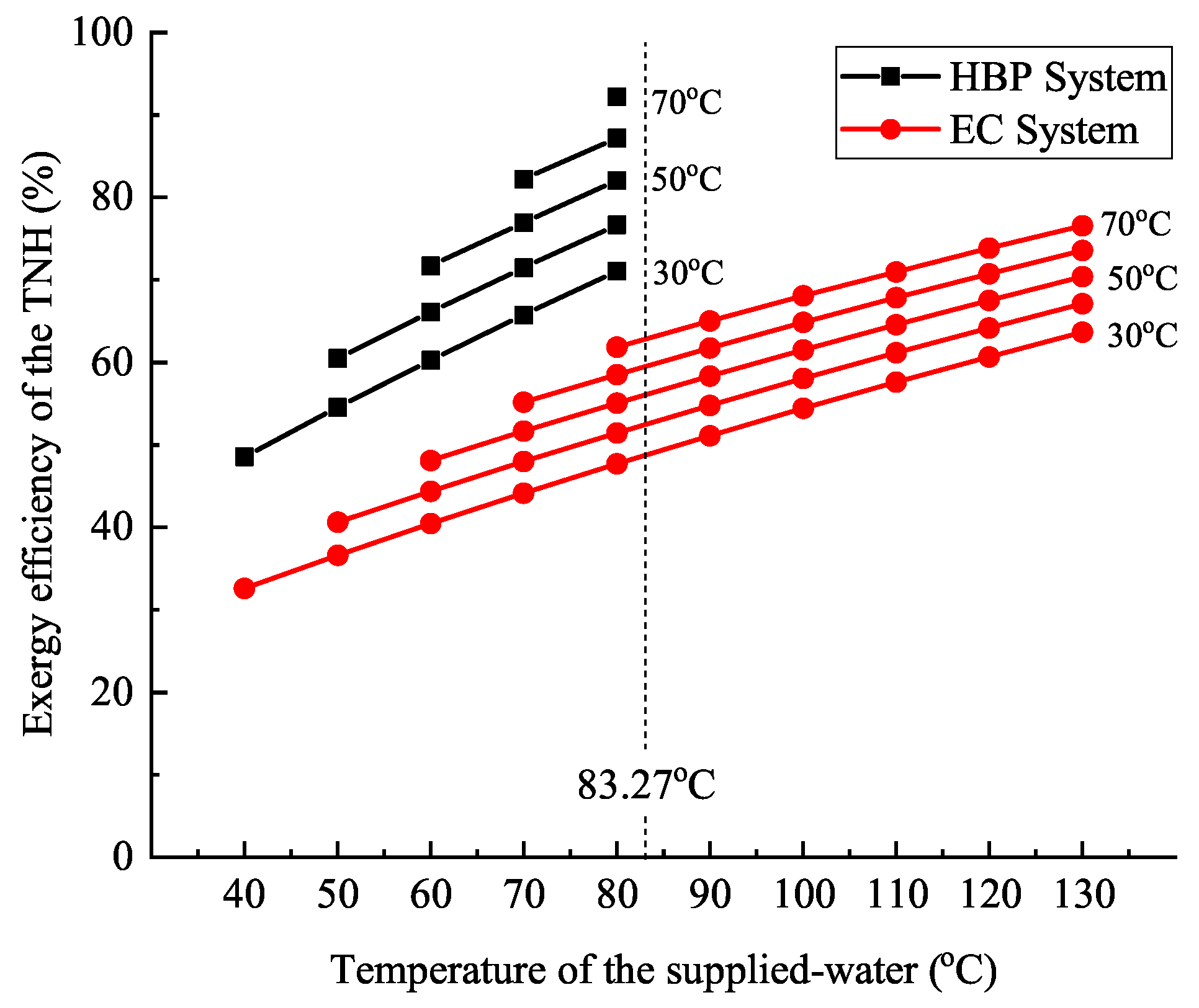
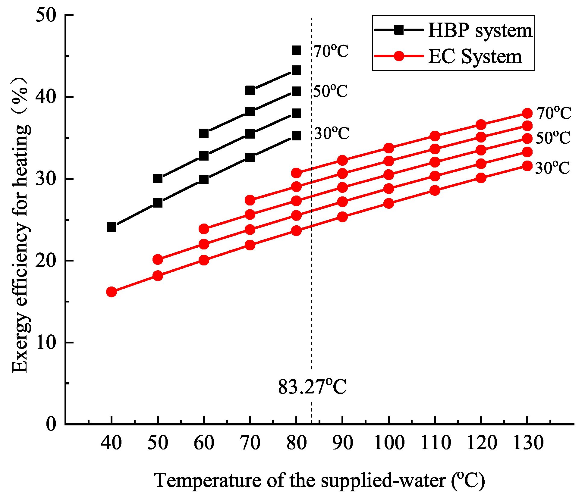
- The conventional exergy-based evaluation of the CHP system strongly relies on the temperatures of the cold-end and the environment, which increases the complexity of further exergy-based research. For example, each cold-end temperature will need a unique diagram to show the exergy efficiencies in the feasible operational region (Figure 6c,f).
- The conventional exergy-based evaluation only concerns the product but ignores the heat sources. For example, the HBP system shows great advantages over the EC system under both the energy-based and the conventional exergy-based evaluations. However, the heating steam of the EC system has a higher level, which is hard to be displayed in these evaluations. Thus, these evaluation methods have limitations when used to compare different types of CHP systems.
- Results based on conventional exergy-based evaluation could also lead in the wrong directions. For example, according to the results in Figure 7 and Figure 8, the increment of the cold-end temperature could increase the exergy efficiency of the CHP system. However, this may raise the bar to recover the low-level waste heat and is opposite to the DH system in the future [30].
4.2.2. Proposal of the Novel Exergy-Based Evaluation
4.2.3. Exergy Analysis under Design Conditions
5. Conclusions
Author Contributions
Funding
Conflicts of Interest
Abbreviations
| CHP | Combined Heat and Power |
| DH | District Heating |
| EC | Extraction Condensing |
| GH | Gland Heater |
| HBP | High Back-Pressure |
| HPT | High-Pressure Turbine |
| LPT | Low-Pressure Turbine |
| MPT | Medium-Pressure Turbine |
| RE | Relative Error |
| RH | Regenerative Heater |
| THA | Turbine Heat Acceptance |
| TMCR | Turbine Maximum Continuous Rating |
| TNH | Thermal Network Heater |
References
- Sipilä, K. Cogeneration, biomass, waste to energy and industrial waste heat for district heating. Adv. Dist. Heat. Cool. (DHC) Syst. 2016, 45–73. [Google Scholar] [CrossRef]
- Antonio, C.S.; David, B.D.; Enrique, R.A. District Heating and Cooling Networks in the European Union; Springer International Publishing: Berlin/Heidelberg, Germany, 2017. [Google Scholar]
- Li, J.; Zhang, Y.; Tian, Y.; Cheng, W.; Yang, J.; Xu, D.; Wang, Y.; Xie, K.; Ku, A.Y. Reduction of carbon emissions from China’s coal-fired power industry: Insights from the province-level data. J. Clean. Prod. 2020, 242, 118518. [Google Scholar] [CrossRef]
- Chen, H.; Xiao, Y.; Xu, G.; Xu, J.; Yao, X.; Yang, Y. Energy-saving mechanism and parametric analysis of the high back-pressure heating process in a 300 MW coal-fired combined heat and power unit. Appl. Therm. Eng. 2019, 149, 829–840. [Google Scholar] [CrossRef]
- Ge, Z.; Zhang, F.; Sun, S.; He, J.; Du, X. Energy Analysis of cascade heating with high back-pressure large-scale steam turbine. Energies 2018, 11, 119. [Google Scholar] [CrossRef]
- Lv, K.; Li, J.; An, J.; Wang, D.; Yu, X. Thermodynamic characteristics of a 330 MW unit with high back-pressure circulating water heating. Turbine Technol. 2019, 61, 59–62+66. [Google Scholar]
- Li, P.; Nord, N.; Ertesvåg, I.S.; Ge, Z.; Yang, Z.; Yang, Y. Integrated multiscale simulation of combined heat and power based district heating system. Energy Convers. Manag. 2015, 106, 337–354. [Google Scholar] [CrossRef]
- Li, Y.; Chang, S.; Fu, L.; Zhang, S. A technology review on recovering waste heat from the condensers of large turbine units in China. Renew. Sustain. Energy Rev. 2016, 58, 287–296. [Google Scholar] [CrossRef]
- Li, W.; Zhao, J.; Fu, L.; Yuan, W.; Zheng, Z.; Li, Y. Energy efficiency analysis of condensed waste heat recovery ways in cogeneration plant. Energy Convers. Manag. 2015, 101, 616–625. [Google Scholar] [CrossRef]
- Li, W.; Tian, X.; Li, Y.; Ma, Y.; Fu, L. Combined heating operation optimization of the novel cogeneration system with multi turbine units. Energy Convers. Manag. 2018, 171, 518–527. [Google Scholar] [CrossRef]
- Zhao, S.; Ge, Z.; He, J.; Wang, C.; Yang, Y.; Li, P. A novel mechanism for exhaust steam waste heat recovery in combined heat and power unit. Appl. Energy 2017, 204, 596–606. [Google Scholar] [CrossRef]
- Ma, L.; Ge, Z.; Zhang, F.; Wei, H. A novel super high back pressure cascade heating scheme with multiple large-scale turbine units. Energy 2020, 201, 117469. [Google Scholar] [CrossRef]
- Chen, H.; Qi, Z.; Chen, Q.; Wu, Y.; Xu, G.; Yang, Y. Modified high back-pressure heating system integrated with raw coal pre-drying in combined heat and power unit. Energies 2018, 11, 2487. [Google Scholar] [CrossRef]
- Ommen, T.; Markussen, W.B.; Elmegaard, B. Lowering district heating temperatures—Impact to system performance in current and future Danish energy scenarios. Energy 2016, 94, 273–291. [Google Scholar] [CrossRef]
- Nesheim, S.J.; Ertesvåg, I.S. Efficiencies and indicators defined to promote combined heat and power. Energy Convers. Manag. 2007, 48, 1004–1015. [Google Scholar] [CrossRef]
- Wang, H.; Jiao, W.; Lahdelma, R.; Pinghua, Z. Techno-economic analysis of a coal-fired CHP based combined heating system with gas-fired boilers for peak load compensation. Energy Policy 2011, 39, 7950–7962. [Google Scholar] [CrossRef]
- Yannay, C.L.; Patricia, G.; Scarlett, C.; Claudio A, Z.; Luis E, A.P. Exergoeconomic valuation of a waste-based integrated combined cycle (WICC) for heat and power production. Energy 2016, 114, 239–252. [Google Scholar] [CrossRef]
- Pouria, A.; Marc A., R.; Ibrahim, D. Greenhouse gas emission and exergo-environmental analyses of a trigeneration energy system. Int. J. Greenh. Gas Control 2011, 5, 1540–1549. [Google Scholar] [CrossRef]
- Emin, A.; Haydar, A.; Arif, H. Advanced exergy analysis of a trigeneration system with a diesel–gas engine operating in a refrigerator plant building. Energy Build. 2014, 80, 268–275. [Google Scholar] [CrossRef]
- Duccio, T.; Daniele, F. Thermo-economic assessment of a micro CHP system fuelled by geothermal and solar energy. Energy 2013, 58, 45–51. [Google Scholar] [CrossRef]
- Yang, Y.; Li, P.; Ge, Z.; Tian, J.; Wang, N.; Song, Z. Green heating: Theory and practice. Sci. China Technol. Sci. 2015, 58, 2003–2015. [Google Scholar] [CrossRef]
- Lund, H.; Ostergaard, P.A.; Chang, M.; Werner, S.; Svendsen, S.; Sorknaes, P.; Thorsen, J.E.; Hvelplund, F.; Mortensen, B.O.G.; Mathiesen, B.V.; et al. The status of 4th generation district heating: Research and results. Energy 2018, 164, 147–159. [Google Scholar] [CrossRef]
- Duan, J.; Zheng, W.; Wang, X.; Hao, Y. Technical and economic analysis of 150MW turbine unit about two reconstruction modes for high back pressure heating. Appl. Mech. Mater. 2013, 291–294, 1708–1713. [Google Scholar] [CrossRef]
- Xue, Y.; Ge, Z.; Yang, L.; Du, X. Peak shaving performance of coal-fired power generating unit integrated with multi-effect distillation seawater desalination. Appl. Energy 2019, 250, 175–184. [Google Scholar] [CrossRef]
- Cristina, S.S.; Marina, O.D.; Fontina, P. Exergy and economic evaluation of a hybrid power plant coupling coal with solar energy. Appl. Sci. 2019, 9, 850. [Google Scholar] [CrossRef]
- STEAG. EBSILON®Professional Online Help: Steam Turbine/General Expander. Available online: https://help.ebsilon.com/EN/webframe.html#Component_6.html (accessed on 20 August 2020).
- Steven, I.G.; Ramon, F.G.; Jose, C.C.; Denis, I.G. Critical review of the first-law efficiency in different power combined cycle architectures. Energy Convers. Manag. 2017, 148, 844–859. [Google Scholar] [CrossRef]
- Wang, J.; Lu, Z.; Li, M.; Lior, N.; Li, W. Energy, exergy, exergoeconomic and environmental (4E) analysis of a distributed generation solar-assisted CCHP (combined cooling, heating and power) gas turbine system. Energy 2019, 175, 1246–1258. [Google Scholar] [CrossRef]
- Stepanov, V.S. Chemical energies and exergies of fuels. Energy 1995, 20, 235–242. [Google Scholar] [CrossRef]
- Lund, H.; Werner, S.; Wiltshire, R.; Svendsen, S.; Thorsen, J.E.; Hvelplund, F.; Mathiesen, B.V. 4th Generation District Heating (4GDH) integrating smart thermal grids into future sustainable energy systems. Energy 2014, 68, 1–11. [Google Scholar] [CrossRef]
- Li, J.; Gao, S.; Li, Y.; Lyu, J.; Gao, Z. Exergy Efficiency Analysis of Heating Steam Pipeline for Cogeneration Power Plant. Electr. Power 2018, 51, 53–58. [Google Scholar]


| Item | Unit | Value |
|---|---|---|
| Gross power output (In THA condition) | MW | 300 |
| Gross power output (In TMCR condition) | MW | 322.20 |
| Net power output (In TMCR condition) | MW | 313.42 |
| Mass flow of the coal | t/h | 96.43 |
| Efficiencies | ||
| Boiler | % | 93 |
| Pipeline | % | 99 |
| Mechanical | % | 99 |
| Generator | % | 99 |
| Pump | % | 83 |
| Pressure losses | ||
| Live steam | % | 2 |
| Reheat steam | % | 10 |
| Pipeline from MPT to LPT | % | 4.5 |
| High-pressure regenerative heater | % | 3 |
| Low-pressure regenerative heater | % | 5 |
| Item | Pressure (MPa) | Temperature (C) | Specific Enthalpy (kJ/kg) | Mass Flow Rate (t/h) |
|---|---|---|---|---|
| Live steam | 16.67 | 538 | 3397.3 | 1017.92 |
| Reheat steam | 3.58 | 538 | 3535.4 | 846.91 |
| Exhaust steam | 0.014 | 52.57 | 2429.3 | 666.63 |
| 1# RH | 6.20 | 390.4 | 3151.5 | 69.41 |
| 2# RH | 3.98 | 332.6 | 3051.3 | 60.00 |
| 3# RH | 1.90 | 442.7 | 3343.3 | 33.66 |
| Deaerator | 0.98 | 355.9 | 3170.5 | 29.60 |
| 5# RH | 0.63 | 295.4 | 3049.9 | 43.69 |
| 6# RH | 0.26 | 128.56 | 2868.2 | 41.50 |
| 7# RH | 0.89 | 96.32 | 2677.8 | 47.60 |
| Items | (%) | (%) | (%) | (%) | (%) | (%) | (%) | (%) | (kJ/kg) |
|---|---|---|---|---|---|---|---|---|---|
| Value | 73.69 | 4.29 | 2.51 | 2.45 | 1.05 | 6.26 | 9.75 | 23.98 | 29,686 |
| Component | Module Type | Parameters |
|---|---|---|
| Boiler | NO. 5 | Reheat steam temperature = 538 C; Live steam pressure = 16.67 MPa; Live steam pressure loss = 14%; Reheat steam pressure loss = 10% |
| Turbines | NO. 122 | Isentropic Efficiency = 83.53–93.56%; Mechanical Efficiency = 99.8%; Heat loss = 0 |
| Generator | NO. 11 | Electrical efficiency = 99% |
| Condenser | NO. 7 | Upper temperature difference = 1 C; Pressure drop = 5 kPa |
| Pump | NO. 8 | Isentropic Efficiency = 83%; Mechanical Efficiency = 99.80% |
| Thermal network heater | NO. 35 | Maximum mass flow = 500 t/h; Dain water temperature = 104 C |
| Pressure-control | NO. 59 | Pressure for DH system ≥ 0.4 MPa |
| Pressure losses | NO. 13 | High-pressure regenerative heater = 3%; Low-pressure regenerative heater = 5%; Pipeline from MPT to LPT =4.5% |
| Feed water preheater | NO. 10 | Pressure loss of feed water = 5 kPa; Upper temperature difference: 1# = −1.7 C, 2#/3# = 0 C, 5# 7# = 2.8 C |
| After cooler | NO. 27 | Lower temperature difference = 5.6 C |
| Items | Unit | EC System | HBP System | Differences |
|---|---|---|---|---|
| Energy of the coal | MW | 797.42 | 795.55 | – |
| Pressure of the heating steam | kPa | 400 | 54 | – |
| Mass flow of the heating steam | t/h | 500 | 703.78 | – |
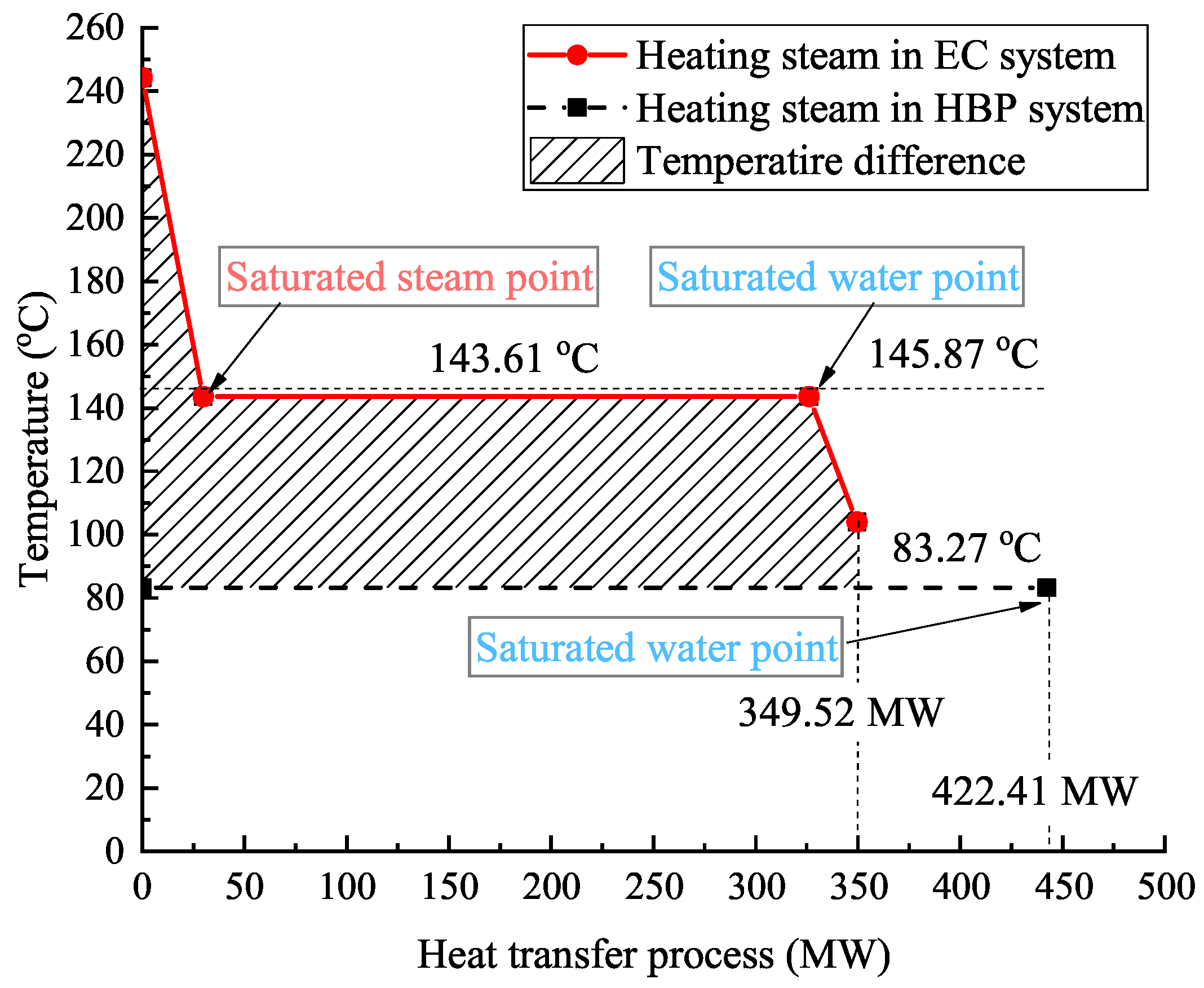
| Temperature of the heating steam | C | 145.87 | 83.27 | – |
| Heating capacity | MW | 349.52 | 442.41 | 92.89 |
| Generation power | MW | 237.19 | 283.48 | 46.29 |
| Generation efficiency () | % | 56.77 | 89.98 | 33.21 |
| Coal consumption rate for generation () | g/kWh | 216.30 | 136.47 | −79.84 |
| Heating efficiency () | % | 92.07 | 92.07 | 0.00 |
| Coal consumption rate for heating () | kg/GJ | 37.04 | 37.04 | 0.00 |
| Gross thermal efficiency () | % | 73.58 | 91.24 | 17.67 |
| Exergy efficiency of DH system ( ) ( = 20 C) | % | 6.82 | 6.82 | 0.00 |
| Exergy efficiency () ( = 20 C) | % | 31.89 | 38.41 | 6.52 |
| Items | Unit | Power-Only System | EC System | HBP System |
|---|---|---|---|---|
| Exergy of the coal | MW | 816.64 | 818.48 | 816.55 |
| Exergy to the live and reheat steam | MW | 423.19 | 424.14 | 423.15 |
| Exergy of the heating steam | MW | – | 121.68 | 103.36 |
| Exergy consumption for heating | MW | – | 241.64 | 208.34 |
| Net generation power | MW | 313.42 | 237.19 | 283.48 |
| Exergy efficiency for generation | % | 38.38 | 41.22 | 46.48 |
© 2020 by the authors. Licensee MDPI, Basel, Switzerland. This article is an open access article distributed under the terms and conditions of the Creative Commons Attribution (CC BY) license (http://creativecommons.org/licenses/by/4.0/).
Share and Cite
Zhao, S.; Wang, W.; Ge, Z. Energy and Exergy Evaluations of a Combined Heat and Power System with a High Back-Pressure Turbine under Full Operating Conditions. Energies 2020, 13, 4484. https://doi.org/10.3390/en13174484
Zhao S, Wang W, Ge Z. Energy and Exergy Evaluations of a Combined Heat and Power System with a High Back-Pressure Turbine under Full Operating Conditions. Energies. 2020; 13(17):4484. https://doi.org/10.3390/en13174484
Chicago/Turabian StyleZhao, Shifei, Weishu Wang, and Zhihua Ge. 2020. "Energy and Exergy Evaluations of a Combined Heat and Power System with a High Back-Pressure Turbine under Full Operating Conditions" Energies 13, no. 17: 4484. https://doi.org/10.3390/en13174484
APA StyleZhao, S., Wang, W., & Ge, Z. (2020). Energy and Exergy Evaluations of a Combined Heat and Power System with a High Back-Pressure Turbine under Full Operating Conditions. Energies, 13(17), 4484. https://doi.org/10.3390/en13174484