Article

Performance Analysis and Optimization of Power Density Enhanced PMSM with Magnetic Stripe on Rotor

School of Mechanical Engineering, Sichuan University, Chengdu 610065, China
*
Author to whom correspondence should be addressed.
Energies 2020, 13(17), 4457; https://doi.org/10.3390/en13174457
Submission received: 10 June 2020 / Revised: 19 August 2020 / Accepted: 25 August 2020 / Published: 28 August 2020
(This article belongs to the Section E: Electric Vehicles)

Abstract

:
A permanent magnet synchronous motor (PMSM) has advantages in applications such as electric vehicles and all-electric-aircraft because of its inherent characteristics of high power density. In order to further improve its power density, this paper proposes a novel rotor structure with a magnetic stripe, based on the “dual stator + Halbach array” topology of the PMSM, which leads to a PMSM with greater power density. Then, this paper proposes characteristic parameters such as the external air gap proportional coefficient K1 and the internal air gap proportional coefficient K2 of the novel rotor structure, and establishes the torque analysis model of the novel rotor structure and the corresponding motor. Simulation results show that the novel rotor structure can increase the average torque. Then, this paper establishes an optimization model, in which K1 and K2 are taken as optimization variables, a torque fluctuation of no more than 5% is set as a constraint, and the maximum average torque is set as the optimization goal. The results show that the optimized novel rotor structure with magnetic stripe can significantly improve the torque performance of the PMSM, and the optimization method proposed is efficient.

1. Introduction

The permanent magnet synchronous motor (PMSM) is widely used in the electric vehicle industry due to its inherent characteristics of high power density [1]. In recent years, it has also received considerable attention in the field of more-electric-aircraft or all-electric-aircraft [2,3].
Torque density and torque fluctuation are two important parameters for measuring the performance of the PMSM. Under the premise that the torque fluctuation is less than a certain value, the larger the average torque, the better the performance of the motor. Among the factors that affect the torque performance of the PMSM, the fundamental wave amplitude of the radial component of the air gap magnetic flux density is generally proportional to the output torque, and it has a strong relationship with the waveform and amplitude of the radial component of the air gap magnetic flux density. If the waveform of the radial component of the air gap magnetic flux density can be improved to make it closer to a sinusoidal shape, or the amplitude of the radial component of the air gap magnetic flux density is increased, or even if the amplitude is greatly increased while sacrificing some sinusoidal shape, the fundamental wave amplitude of the radial component of the air gap magnetic flux density can be increased; the improvement of the fundamental wave amplitude of the radial component of the air gap magnetic flux density has always been the focus of research at home and abroad.
The amplitude and waveform of the air gap magnetic flux density are mainly determined by the magnetic field generated by the stator winding and the magnetic field generated by the permanent magnets. Therefore, the arrangement of the permanent magnets and the permanent magnet core of the rotor is very important for the torque performance of the PMSM. From the perspective of the arrangement of the permanent magnets, the main topological structures of the permanent magnet motor rotors include an interior permanent magnet machine (IPM), a surface mounted permanent magnet machine (SMPM), a heterogeneous pole permanent magnet machine (HPM), and an asymmetric salient surface mounted permanent magnet machine (APM) [4].
The permanent magnets of the IPM are embedded in the rotor, and are arranged in a circumferential direction to form a multi-pole motor [4]. Two adjacent permanent magnets with opposite N–S magnetic poles form one pole of the rotor. The arrangement of permanent magnets has evolved from a “ V ” type to a “ V ¯ ” type or even a “ W ¯ ” type [5], and the structural parameters have also been continuously optimized. The amplitude of the air gap magnetic flux density of the PMSM has been further improved with the help of high-performance rare earth permanent magnets [6,7]. Based on the IPM, some scholars use mechanical structures to dynamically change the position of the magnetically permeable material to dynamically improve the waveform and amplitude of the air gap magnetic density [8], so as to achieve good results.
The permanent magnets of the SMPM are installed on the surface of the rotor, and the magnetization direction of the permanent magnets in the traditional structure is arranged along the radial direction or in the direction opposite of the rotor [4,9]. A Halbach permanent magnet array is often used to increase the amplitude of the air gap magnetic density because its magnetic flux can be superposed on one side [10,11,12]. In recent years, the outer rotor permanent magnet synchronous motor with a Halbach array has gained the advantages of high air gap magnetic flux density and high speed, and has gradually attracted the attention of researchers and motor manufacturers [13,14,15]. In order to further improve the air gap magnetic density amplitude or waveform, some scholars started from the air gap magnetic field source, that is the permanent magnets. They divided the permanent magnets corresponding to each pole into several magnetic subassemblies, and then optimized the structural parameters such as quantity and thickness of the permanent magnets, the circumferential span of the permanent magnets, and depth of the base, which improved the air gap flux density waveform formed by the permanent magnets and resulted in the HPM [16]. The HPM can be regarded as a result of differentiating the permanent magnets and cores on the surface of an SMPM and optimizing the structural parameters. Other scholars started from the magnetic flux transmission path, reducing the magnetic resistance. They kept the arrangement of the rotor permanent magnets unchanged, and installed a trapezoidal iron core structure on the side of the permanent magnet while retaining the air area between the poles, and then optimized the parameters of the trapezoidal iron core structure, which improved the amplitude of the magnetic flux density formed in the air gap by the permanent magnets and resulted in an APM [17]. Compared with a SMPM, an APM has more structural parameters. After optimization, the number of permanent magnets can be reduced, and the output torque of the motor can be increased, thereby improving the power density of the PMSM. Moreover, it is needed to calculate the output torque for the PMSM with improved structure. Theoretical analysis is used for such calculation for a simple motor structure [18], while Finite Element Applications (FEA) is used for the complicated structures, such as for the flux-assisted spoke-type permanent magnet synchronous motor [7], the in-wheel motor [19] and other types of motors [20,21]. FEA is effective and reliable for simulating the magnetic field of motors as was proved by experiment in [7] and [19,20,21].
The above research shows that the improvement of the rotor structure is an important way to improve the torque performance of the PMSM, and exploring the new structure of the rotor has also become a research hotspot. In the above studies, whether it concerns the interior permanent magnet rotor structure or the surface-mounted permanent magnet rotor structure, there is no solid structure in the air gap that is located between the permanent magnet cylinder and the stator, therefore, when the theoretical analysis is carried out with a small air gap thickness, the radial component of the air gap magnetic flux density can be assumed to be a constant value [18]. The improvement of rotor structure is made to improve the amplitude and waveform of the radial component of magnetic flux density of the air gap as a whole, and good results were achieved. The thickness of the air gap should increase in consideration of factors such as heat dissipation and difficulty in manufacturing, however, the amplitude of air gap magnetic flux density will be reduced accordingly. In order to avoid a large decrease in the amplitude of the air gap magnetic flux density with increasing thickness of the air gap and to improve the waveform of the air gap magnetic flux density, a novel rotor structure is proposed in which magnetic stripes that extend into the air gap are installed between the rotor permanent magnets. The rotor structure of the surface-mounted permanent magnet synchronous motor is taken as an example for simulation analysis and structural parameter optimization.

2. Novel Rotor Structure with Magnetically Conductive Strips

2.1. Analysis of the Existing Rotor Structure Characteristics of SMPM

The rotor of a traditional surface mounted permanent magnet synchronous motor is composed of a shaft, a rotor backiron, a magnetically inert region and a permanent magnet [6]. The shaft is generally a solid shaft made of low-permeability material, the rotor backiron is a hollow shaft made of high-permeability electrical steel, and the magnetically inert region is used to isolate the shaft and rotor backiron. The radially magnetized permanent magnet segment is firmly fixed on the rotor backiron. The width of the permanent magnet is 2πα/p, where α is the pole arc coefficient and p is the number of pole pairs. The entire rotor is separated from the stator by an air gap.
For the SMPM, in addition to the above-mentioned radial magnetization arrangement, the most common type is the Halbach array arrangement. The magnetization direction of the permanent magnets of the Halbach array is not limited to the radial direction, which results in superposition of magnetic flux on one side [22]. Therefore, the Halbach array can significantly increase the magnetic density amplitude in the air gap and improve its sinusoidal property. In recent years, in order to further increase the power density of the PMSM, the external rotor permanent magnet synchronous motor with a Halbach array has appeared. It can both generate a higher amplitude of air gap magnetic flux density and higher speed, however, the heat dissipation must be considered when the power density increases, so a heat sink and forced air cooling was used to enhance heat dissipation [13,14].
There is a rotor and a stator in the motors described above, in fact, the radial flux permanent magnet synchronous motor also has other structures, such as one stator between two rotors, one rotor between two stators, or even multi-stage rotor-stators. Compared with the traditional motor structure described above, they have one or more sets of output torque, so their output torque is significantly increased under the same conditions [23,24].

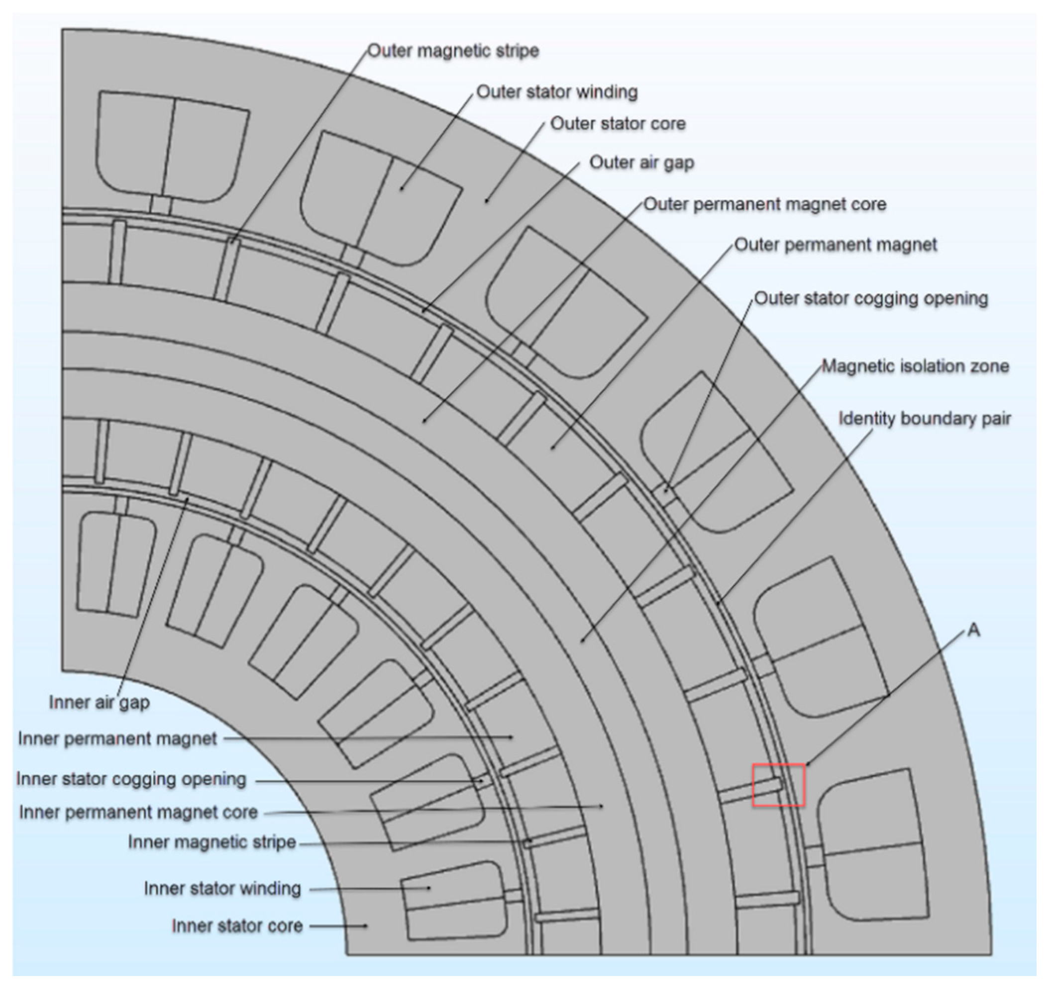
2.2. Novel Rotor Structure and Work Principle

When the theoretical analysis of the magnetic circuit of the SMPM is carried out with a small air gap thickness, the radial component of the air gap magnetic flux density can be assumed to be a constant value. Therefore, the two-dimensional distribution of air-gap magnetic flux density is simplified to a one-dimensional problem where the air-gap magnetic flux density only changes with the electrical angle, which is convenient for analysis. In fact, when the thickness of the air gap is increased by taking into consideration factors such as heat dissipation and difficulty in manufacturing, and especially the compact structure of the motor, there is no better way of heat dissipation except for forced air cooling by means of an air gap. The amplitude of the air gap magnetic flux density decreases accordingly, and the radial component of the air gap magnetic flux density is no longer a constant value in the radial direction. The radial component of the air gap magnetic flux density is small at both ends of the air gap and large in the middle, and the position of its peak is determined by factors such as the stator magnetic field waveform, rotor magnetic field waveform and their relative strength. In order to avoid a large decrease in the amplitude of the air gap magnetic flux density when increasing the thickness of the air gap and to improve the waveform of the air gap magnetic flux density, a novel rotor structure is proposed in which magnetic stripes are installed between the rotor permanent magnets and extend into the air gap.
The stripe of structure occupies the air area between the permanent magnets of the rotor of the traditional SMPM with high permeability material and makes it extend into the air gap. Therefore, the magnetic flux generated by the permanent magnet can directly reach the inside of the air gap by means of a magnetically conductive strip made of a high permeability material, which indirectly reduces the air gap thickness while ensuring good heat dissipation conditions. Because the magnetic permeability of the magnetic stripe is much larger than that of air, the amplitude of the air gap magnetic flux density can significantly increase. In addition, in order to further increase the output torque, the structure with one rotor between two stators is used in this paper. As shown in Figure 1, the rotor is composed of an inner permanent magnet, an inner permanent magnet core, a magnetic isolation zone, an outer permanent magnet core and an outer permanent magnet, in order from the the inside to the outside. Among them, the permanent magnets are arranged in the form of a Halbach array. The permanent magnet core has a small thickness and is made of high permeability materials. The magnetic-isolation zone is made of low-permeability materials, which minimizes the coupling relationship between the torque generated at the inner gap and the torque generated at the outer gap. In addition, the rotor structure should also include some auxiliary structures, such as the rotor support structure and permanent magnet fixing structure, and the path of the torque output.

2.3. Structural Parameters and Characteristics

In order to accurately describe the structure of the magnetic stripe between the two adjacent permanent magnets of the rotor, this paper defines two structural parameters. They are called the external air gap proportional coefficient K1 and the internal air gap proportional coefficient K2, which are defined as follows:
K 1 = δ o u t g o u t
K 2 = δ i n g i n
As shown in Figure 2, δout is the length of the outer magnetic stripe above the outer permanent magnet and gout is the thickness of the outer air gap; similarly, δin is the length of the inner magnetic stripe above the inner permanent magnet and gin is the thickness of the inner air gap.
Compared with the conventional SMPM, this structure improves the rotor structure and keeps the stator structure unchanged. In fact, the geometric shape of the magnetic strip end that extends into the air gap and the width of the magnetic strip in the circumferential direction are all closely related to the torque performance of the PMSM. The geometric shape of the magnetic stripe selected in this paper is a sector shape on the axial section of the motor, and the width of the magnetic stripe in the circumferential direction is equal to the circumferential width of gap between the two adjacent permanent magnets.

3. Modeling and Analysis of PMSM with Magnetic Stripe on Rotor

3.1. Modeling of PMSM with Rotor with Magnetic Stripe Structure

In order to study the torque performance of the motor, this paper first establishes a three-dimensional structure model of the stator and rotor of the radial flux permanent magnet synchronous motor. The main structural parameters are shown in Table 1. It is worth pointing out that a larger air gap thickness is necessary due to insufficient stiffness of the dual air gap structure—a 2.5 mm gap length is taken as an example.
When COMSOL Multiphysics is used in simulation calculations, in order to correctly solve the output torque of the three-dimensional model, after determining the structural parameters of the three-dimensional model of the PMSM, it is necessary to determine its electromagnetic parameters and set the physical field, then add the necessary continuity conditions and set the rotor speed, and finally mesh and use the Maxwell tensor equation built into COMSOL Multiphysics to obtain the torque and magnetic flux density distribution of the motor model. The electromagnetic parameters of the PMSM are shown in Table 2.
In order to speed up calculations, the 1/4 sector form is used. Then the characteristics of the circumferential periodic arrangement on the motor structure are fully utilized, and with the built-in periodic conditions of the software, the complete torque output and the complete magnetic flux density distribution can be obtained.

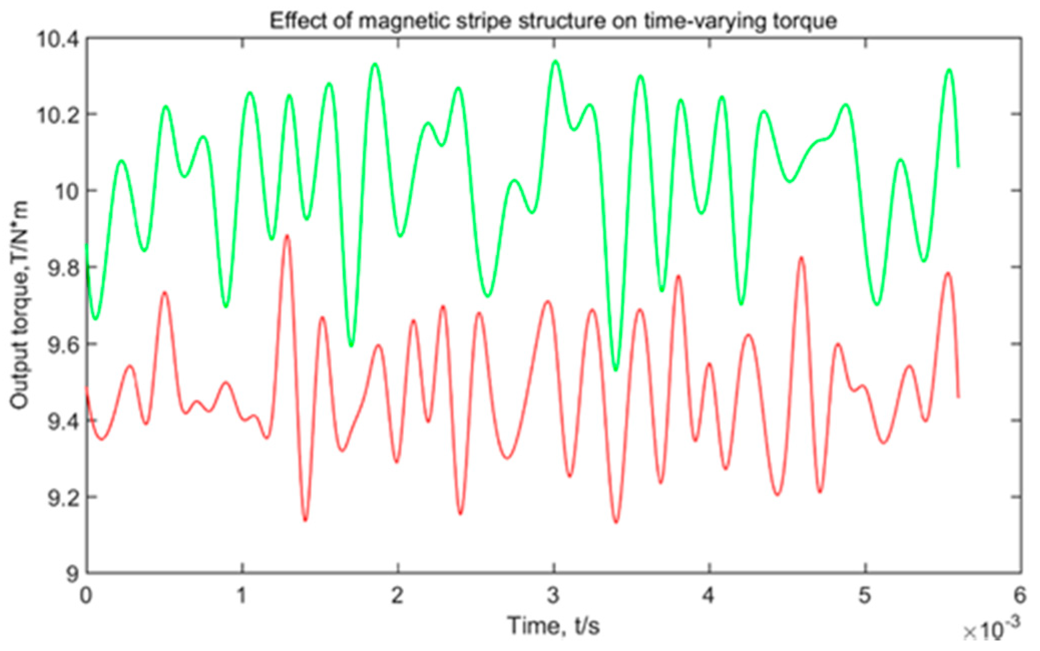
3.2. Torque Calculation and Comparative Analysis

In order to correctly evaluate the output torque performance of PMSM, two general indicators are used to describe the magnitude and fluctuation of the output torque. They are called the average torque Trms and the torque fluctuation Trip, which are defined as follows:
T r m s = t 1 t 2 T t d t t 2 t 1
T r i p = T max T min T r m s × 100 %
In the Equations (3) and (4), Tt is the time-varying torque, Tmax is the maximum torque in this period, and Tmin is minimum torque in this period.
The larger the Trms, the stronger the drive capacity of the motor. The smaller the Trip, the smoother the output torque of the motor, that is, the larger the Trms while the smaller the Trip, the better the torque performance of the motor.
In order to analyze the influence of the novel rotor structure on the torque performance of the PMSM, a simulation calculation was performed based on the torque analysis model of the PMSM established above. As shown in Figure 3, the output torque of the motor model without the magnetic stripe structure is shown in the red line. In the motor model with the magnetic stripe structure, K1 and K2 are taken as 0.55, and its output torque is shown in the green line.
According to Equations (3) and (4), Table 3 can be obtained by processing the original time-varying torque data shown in Figure 3.
As can be seen from Table 3, compared with the average torque of the non-magnetic stripe structure, the average torque of the PMSM with the magnetic stripe structure increases by 5.87%, and the torque fluctuation of the PMSM with the magnetic stripe structure increases by 2.9%. It shows that the novel rotor structure can significantly enhance the power density of the PMSM. The parameter combination (K1, K2) has a direct impact on torque performance. In order to further suppress the torque fluctuation while increasing the average torque, it is necessary to analyze the coupling relationship between K1 and K2 and their influence on torque performance, or even optimize the parameter combination (K1, K2).

4. Torque Performance Analysis of Novel Rotor Structure

4.1. Analysis of the Coupling Relationship between the Air Gap Proportionality Coefficients

The magnetic flux density distribution map can be obtained by the torque analysis model of the PMSM, as shown in Figure 4. The radial component of the magnetic flux density along the rotor circumferential direction at the centerline of the magnetic isolation zone can be obtained by measurement, as shown in Figure 5. It can be seen that the magnetic flux density of the magnetic isolation zone is extremely small and its peak value at the center line of the magnetic isolation zone does not exceed 3 × 10⁻⁴ T, which is negligible compared to the peak value of the air gap magnetic flux density. That is, the result of the magnetic isolation zone is good, and there is almost no magnetic leakage between the internal permanent magnets and the external permanent magnets. Therefore, it can be considered that there is no coupling relationship between K1 and K2; they are two independent variables.

4.2. Relationship between Air Gap Proportional Coefficient and Torque Performance

For the convenience of description, in this paper, the torque generated between the outer stator and the outer permanent magnets of the rotor can be defined as the external torque, and the torque generated between the inner stator and the inner permanent magnets of the rotor can be defined as the internal torque. Since K1 and K2 are two independent variables, the relationship between K1 and the average torque and the torque fluctuation of the external torque, and the relationship between K2 and the average torque and torque fluctuation of the internal torque can be studied separately. When studying the effect of K1 on the external torque performance, the remanence of the inner permanent magnets and the current of the inner stator winding can be set to 0, so the data of the external torque change with time can be obtained; that data can be processed to get the average torque and torque fluctuation of external torque. Then the value of K1 can be changed to get the torque performance under different K1, and finally fit the sampling data to get the relationship between K1 and the performance of the external torque, as shown in Figure 6. Similarly, the relationship between K2 and the performance of internal torque can be obtained, as shown in Figure 7.
Looking at Figure 6 and Figure 7, it can be seen that the average external torque has a maximum value when K1 falls near 0.35, and at the same time, the fluctuation of external torque is small. The average of internal torque has a maximum value when K2 falls near 0.55, at the same time, the fluctuation of internal torque is small. In order to further obtain the optimal combination of K1 and K2, it is necessary to continue to do parameter optimization.

5. Structural Parameter Optimization of Novel Rotor Structure

5.1. Optimization Model and Procedure

K1 and K2 are characteristic parameters for the rotor, which are defined in Section 2.3 as shown in Figure 2, and there is no coupling relationship between them, as mentioned in Section 4.1. Each one has its own effect on the average torque and the torque fluctuation of the dual stator motor respectively according to the analysis in Section 4.2 above. In Section 3.2 above, it can be seen that the driving capacity of the motor becomes stronger as the average torque increases, and the output torque of the motor becomes smoother as the torque fluctuation decreases. Therefore, there is a combination of characteristic parameters for the dual stator motor to make the average torque of the dual stator motor become larger and the torque fluctuation less. Under the premise that the torque fluctuation is less than a certain value, the larger the average torque, the better the torque performance of the motor. At the same time, considering that K1 and K2 are two independent variables, when the structural parameters of the novel rotor structure are optimized, K1 and K2 are taken as optimization variables, torque fluctuation of the total torque of no more than 5% is taken as a constraint, and the maximum average torque is taken as the optimization goal. The corresponding optimization procedure is as follows:
(1)
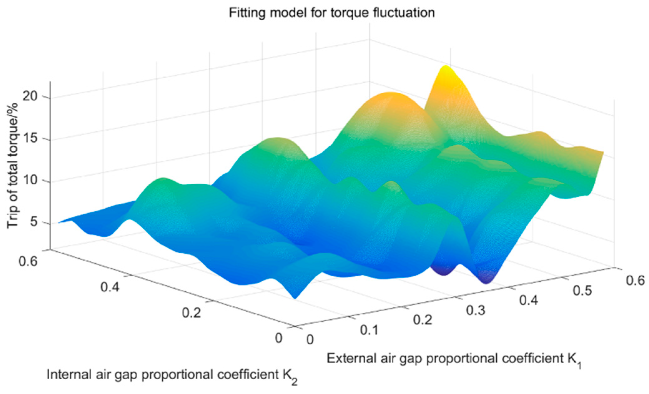
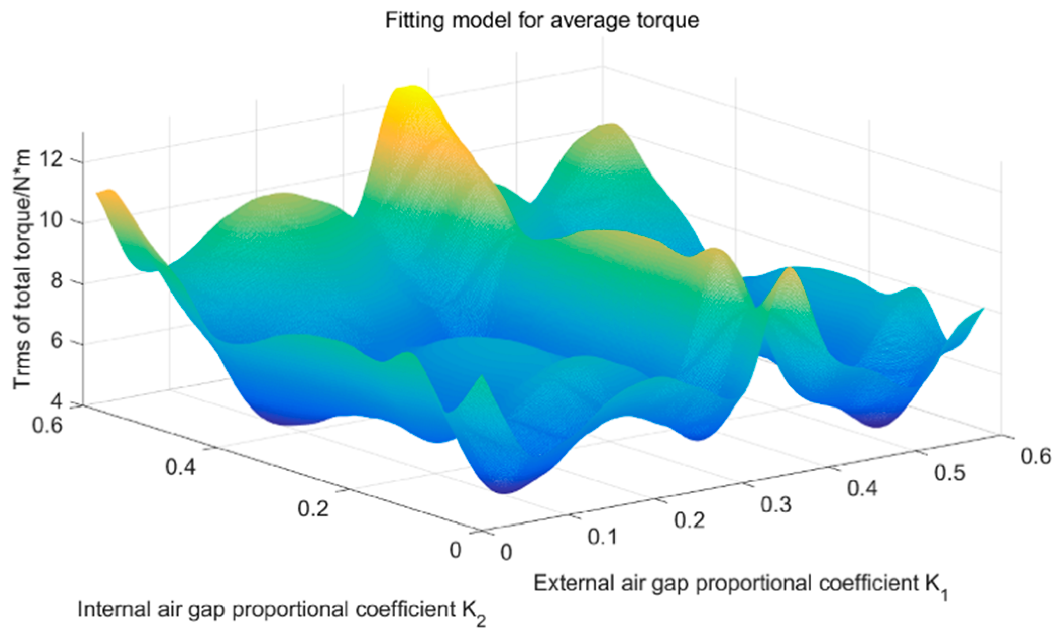
Draw three-dimensional fitting graph of K1 and K2 and the average torque of the total torque, and the three-dimensional fitting graph of K1 and K2 and the torque fluctuation of the total torque. Since K1 and K2 are two independent variables, and the data of the internal torque and external torque change over time, the internal torque and external torque can be added based on time, and then the average torque of the total torque and torque fluctuation of the total torque under the combination of (K1, K2) can be obtained according to the Equations (3) and (4) Finally, the three-dimensional fitting graph of K1 and K2 and the average torque of the total torque can be obtained, as shown in Figure 8. Similarly, the three-dimensional fitting graph of K1 and K2 and the torque fluctuation of the total torque can be obtained, as shown in Figure 9.
(2)
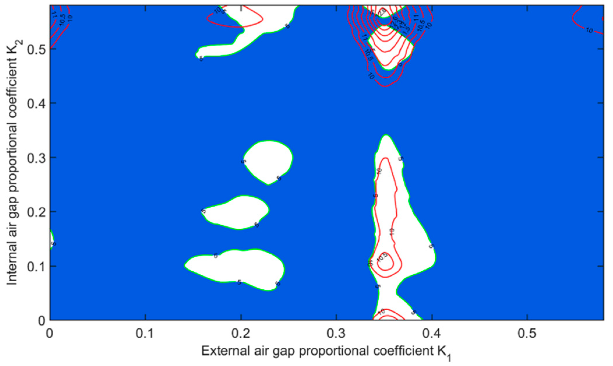
Get the feasible region X. Add the constraint Trip ≤ 5% based on the previous steps; the feasible region X of (K1, K2) can be obtained, as shown by the white area in Figure 10.
(3)
Get the optimal solution. The maximum value T max in the corresponding value range can be obtained, when the feasible region X is taken as the definition domain, by the graphical method shown in Figure 10, in which the contours of average torque can be used to find the maximum value in the feasible region X, or by numerical method. The maximum value of the average torque of the total torque is obtained when Trip ≤ 5% is satisfied.

5.2. Optimization Results and Verification

According to the optimization model, the optimization results can be obtained, as shown in Equation (5):
{ T max = 12.9730 N · m ( K 1 * , K 2 * ) = ( 0.35 , 0.5560 ) T r i p = 5 % .
Then, the optimal combination of (K1, K2), that is (0.35, 0.5560), is used to establish the torque analysis model of the verification experiment according to Section 3, and the result of the verification experiment is shown in Figure 11. Then the comparison of the result of optimization and the verification experiment can be obtained according to Equations (3) and (4), as shown in Table 4.
As shown in Figure 11 and Table 4, the result of the simulation verification experiment shows that the average torque at (K1, K2) = (0.35, 0.5560) is 12.9244 N·m, and the corresponding torque fluctuation is 3.74%, that is, the relative error between the simulation verification result and optimization result is 0.38%, and the torque fluctuation of the verification experiment is less than the torque fluctuation of optimization. It can be seen that the optimization results are in good agreement with the simulation results.
The effect of parameter optimization on the performance of torque can be obtained, as shown in Table 5. After parameter optimization, the average torque can be improved by 28.89% and the torque fluctuation can be reduced by 52.42%. In the example, the thickness of the air gap is taken as 2.5 mm; when the thickness of air gap is taken smaller, the average torque can be increased, but its increment can be reduced.

6. Conclusions

This paper proposes a novel structure with a magnetic stripe based on the “dual stator + Halbach array” topology of the PMSM for enhancing power density. The basic correlation of the engine parameters and the resulting torque are obtained. The study of engine performance was done using analytical calculations and COMSOL Multiphysics. Optimization of the proposed construction was performed in which the maximum average torque was the goal function, and the fluctuation of the torque was a limitation, as a result of which the main design parameters are obtained. The research results are concluded as follows:
(1)
The structure of the rotor with magnetic stripes has a significant effect on the improvement of the average torque of the motor. Compared with the average torque of the non-magnetic stripe structure, when the magnetic stripe structure is taken as K1 = K2 = 0.55, the average torque increases by 5.87%.
(2)
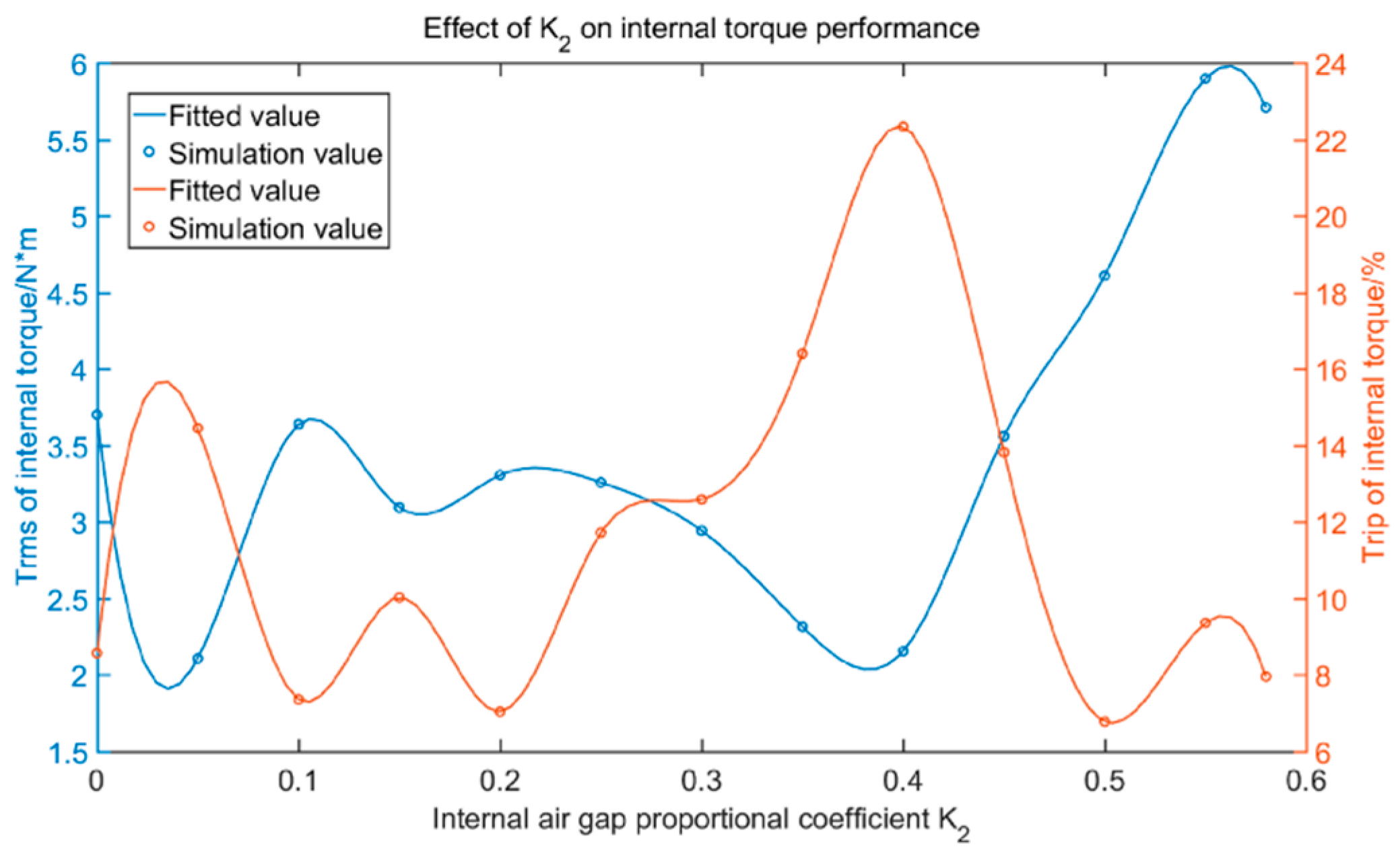
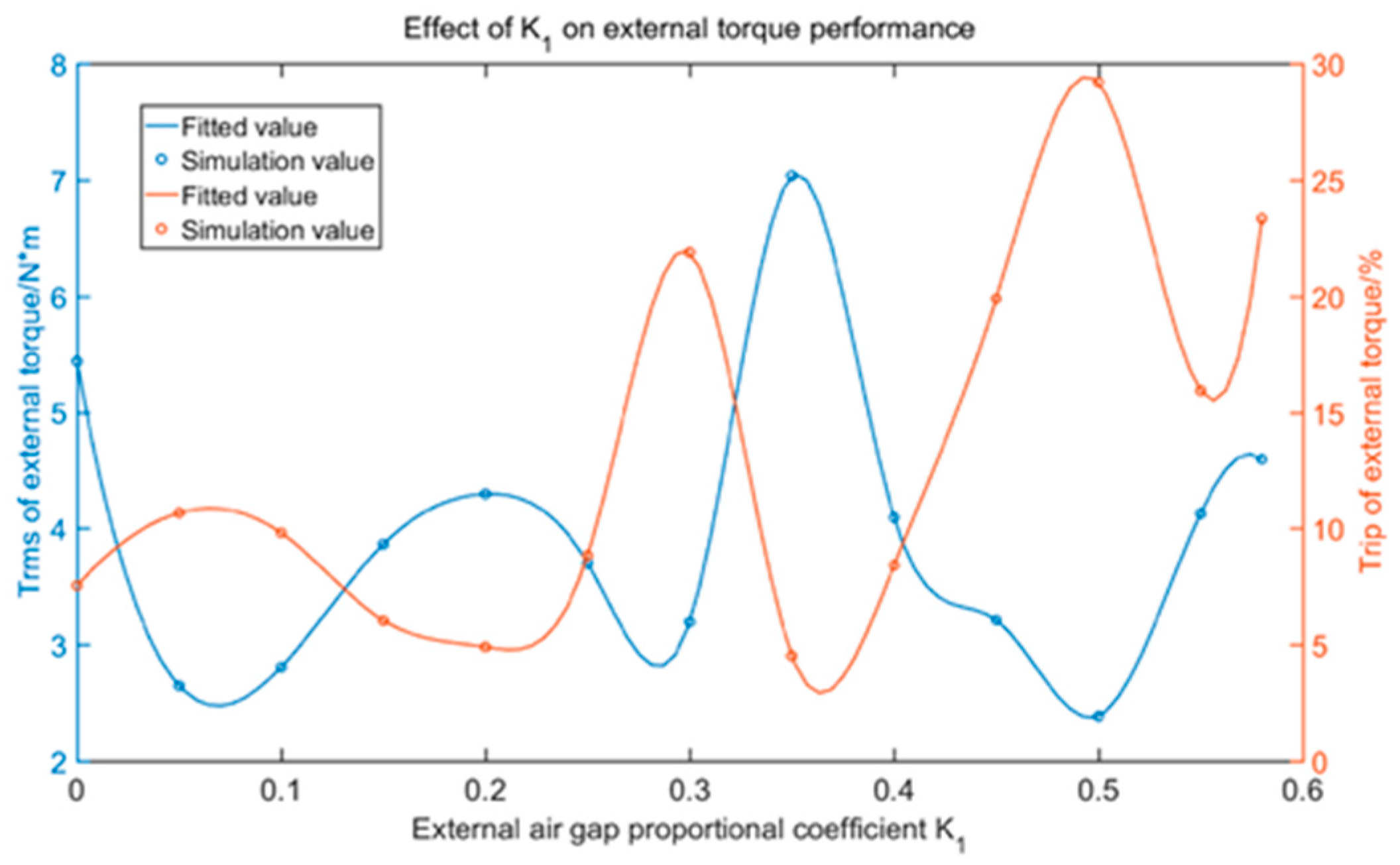
The relationship between the air gap proportional coefficient and the torque performance is very close, and the average torque of the external and internal torque has a peak value. When the external air gap proportional coefficient K1 falls near 0.35, the average torque of the external torque reaches a peak value, and when the internal air-gap proportional coefficient K2 falls near 0.55, the average torque of the internal torque reaches a peak value, as shown in Figure 6 and Figure 7.
(3)
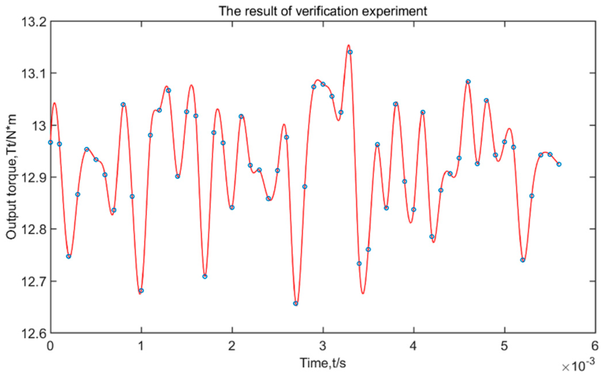
The optimization method is proposed for a novel rotor structure with magnetic stripes. Take K1 and K2 as optimization variables, and take Trip as the total torque with no more than 5% as a constraint, and take the maximum average torque as the optimization goal. The optimization results show that under the premise that Trip ≤ 5%, the average torque of the PMSM with magnetic stripes has the biggest increase when (K1, K2) = (0.35, 0.5560). It can reach 12.9244 N·m, increases by 28.89% compared with the average torque of the PMSM without optimization, and the optimization method proposed is efficient. After parameter optimization, the power density of the PMSM was further enhanced. In the example, the thickness of the air gap is taken as 2.5 mm, when the thickness of the air gap is taken to be smaller, the average torque can be increased, but its increment can be reduced.
These results were obtained by FEA, which has been proven to be effective and reliable for simulating the magnetic field of motors in [7] and [19,20,21]. It is worth pointing out that the novel structure proposed in this article may increase the complexity of the rotor structure, and experiments need to be enriched.

Author Contributions

Conceptualization, J.Y.; methodology, J.Y. and W.W.; software, W.W. and J.Z.; validation, W.W. and J.Z.; formal analysis, J.Y., S.T. and S.Z.; data curation, S.T. and S.Z.; writing—original draft preparation, J.Y. and W.W.; writing—review and editing, W.W.; project administration, J.Y.; All authors have read and agreed to the published version of the manuscript.

Funding

This research was funded by the China University Research Fund, grant number 2010SCU2101.

Conflicts of Interest

The authors declare no conflict of interest.

References

  1. El-Refaie, A.; Osama, M. High Specific Power Electrical Machines: A System Perspective. In Proceedings of the 2017 20th International Conference on Electrical Machines and Systems (ICEMS), Sydney, NSW, Australia, 11–14 August 2017; pp. 1–6. [Google Scholar]
  2. Zhang, X.; Haran, K.S. High-Specific-Power Electric Machines for Electrified Transportation Applications-Technology Options. In Proceedings of the IEEE Energy Conversion Congress and Exposition (ECCE), Milwaukee, WI, USA, 18–22 September 2016; pp. 1–8. [Google Scholar]
  3. Luongo, C.; Masson, P.; Nam, T.; Mavris, D.; Kim, H.; Brown, G.; Waters, M.; Hall, D. Next Generation More-Electric Aircraft: A Potential Application for HTS Superconductors. IEEE Trans. Appl. Supercond. 2009, 19, 1055–1068. [Google Scholar] [CrossRef]
  4. Kasha, A.; Lin, R.; Sudhoff, S.; Chalfant, J.; Alsawalhi, J. A Comparison of Permanent Magnet Machine Topologies for Marine Propulsion Applications. In Proceedings of the 2017 IEEE Electric Ship Technologies Symposium (ESTS), Arlington, VA, USA, 14–17 August 2017; pp. 437–444. [Google Scholar]
  5. Wang, A.; Jia, Y.; Soong, W.L. Comparison of Five Topologies for an Interior Permanent-Magnet Machine for a Hybrid Electric Vehicle. IEEE Trans. Magn. 2011, 47, 3606–3609. [Google Scholar] [CrossRef]
  6. Chen, Z.; Ma, H.; Li, Z. Rotor Parameter Analysis for Surface-Mounted and Interior Hybrid Permanent Magnet Synchronous Machine. In Proceedings of the 2016 19th International Conference on Electrical Machines and Systems (ICEMS), Chiba, Japan, 13–16 November 2016; pp. 1–5. [Google Scholar]
  7. Önsal, M.; Cumhur, B.; Demir, Y.; Yolacan, E.; Aydin, M. Rotor Design Optimization of a New Flux-Assisted Consequent Pole Spoke-Type Permanent Magnet Torque Motor for Low-Speed Applications. IEEE Trans. Magn. 2018, 54, 1–5. [Google Scholar] [CrossRef]
  8. Baoquan, K.; Chunyan, L.; Shukang, C. Flux-weakening-characteristic analysis of a new permanent magnet motor synchronous motor used for electric vehicles. IEEE Trans. Plasma Sci. 2010, 39, 511–515. [Google Scholar] [CrossRef]
  9. Dubois, M.R.; Trovao, J.P. EMF Waveform Optimization using the Permanent Magnet Volume-Integration Method. CES Trans. Electr. Mach. Syst. 2017, 1, 189–198. [Google Scholar] [CrossRef]
  10. Dubois, M.R.; Trovão, J.P.F. Motor Drive with Halbach Permanent Magnet Array for Urban Electric Vehicle Concept. In Proceedings of the 2015 IEEE Vehicle Power and Propulsion Conference (VPPC), Montreal, QC, Canada, 19–22 October 2015; pp. 1–6. [Google Scholar]
  11. Sui, Y.; Liu, Y.; Tong, C.; Yu, B.; Cheng, L. Magnetic System Study of a Halbach Compound-Structure PMSM Used for Hybrid Electric Vehicles. In Proceedings of the 2014 17th International Conference on Electrical Machines and Systems (ICEMS), Hangzhou, China, 22–25 January 2015; pp. 1173–1177. [Google Scholar]
  12. Galea, M.; Papini, L.; Zhang, H.; Gerada, C.; Hamiti, T. Demagnetization Analysis for Halbach Array Configurations in Electrical Machines. IEEE Trans. Magn. 2015, 51, 1–9. [Google Scholar] [CrossRef]
  13. Yoon, A.; Yi, X.; Martin, J.; Chen, Y.; Haran, K. A High-Speed, High-Frequency, Air-Core PM Machine for Aircraft Application. In Proceedings of the 2016 IEEE Power and Energy Conference at Illinois (PECI), Urbana, IL, USA, 19–20 February 2016. [Google Scholar]
  14. Golovanov, D.; Galea, M.; Gerada, C. High Specific Torque Motor for Propulsion System of Aircraft. In Proceedings of the 2016 International Conference on Electrical Systems for Aircraft, Railway, Ship Propulsion and Road Vehicles & International Transportation Electrification Conference (ESARS-ITEC), Toulouse, France, 2–4 November 2016. [Google Scholar]
  15. Cho, S.; Jeong, G.; Liu, H.C.; Ham, S.-H.; Lee, J. Design and Performance Analysis of Outer Rotor Fan-Type PMSM for Power Density Improvement. In Proceedings of the 2016 IEEE Conference on Electromagnetic Field Computation (CEFC), Miami, FL, USA, 13–16 November 2016. [Google Scholar]
  16. Kasha, A.E.; Sudhoff, S.D. Multi-objective design optimization of a surface-mounted modular permanent-magnet pole machine. In Proceedings of the 2016 IEEE Power and Energy Conference at Illinois (PECI), Urbana, IL, USA, 19–20 February 2016; pp. 1–7. [Google Scholar]
  17. Alsawalhi, J.Y.; Sudhoff, S.D. Design Optimization of Asymmetric Salient Permanent Magnet Synchronous Machines. IEEE Trans. Energy Convers. 2016, 31, 1315–1324. [Google Scholar] [CrossRef]
  18. Lin, R.; Sudhoff, S.D. A Hybrid Model to Calculate Air Gap Flux Density for a V-Shape Interior Permanent Magnet Machine. In Proceedings of the 2016 IEEE Power and Energy Conference at Illinois (PECI), Urbana, IL, USA, 19–20 February 2016; pp. 1–7. [Google Scholar]
  19. Shi-Uk, C.; Seok-Hwan, M.; Dong-Jun, K.; Jong-Moo, K. Development of a 20Pole-24Slot SPMSM with Consequent Pole Rotor for In-Wheel Direct Drive. IEEE Trans. Ind. Electron. 2015, 63, 302–309. [Google Scholar] [CrossRef]
  20. Qu, H.; Zhu, Z.Q.; Li, H.Y. Analysis of Novel Consequent Pole Flux Reversal Permanent Magnet Machine. In Proceedings of the IEEE Energy Conversion Congress and Exposition (ECCE), Baltimore, MD, USA, 29 September–3 October 2019; pp. 5223–5230. [Google Scholar]
  21. Yang, H.; Zhu, Z.Q.; Lin, H.; Li, H.; Lyu, S. Analysis of Consequent-Pole Flux Reversal Permanent Magnet Machine with Biased Flux Modulation Theory. IEEE Trans. Ind. Electron. 2020, 67, 2107–2121. [Google Scholar] [CrossRef]
  22. Zhu, Z.; Howe, D. Halbach permanent magnet machines and applications: A review. IEE Proc. Electr. Power Appl. 2001, 148, 299. [Google Scholar] [CrossRef]
  23. Bomme, E.; Foggia, A.; Chevalier, T. Double Air-gaps Permanent Magnet Synchronous Motors Analysis. In Proceedings of the 2018 18th International Conference on Electrical Machines(ICEM), Vilamoura, Portugal, 6–9 September 2008; pp. 1–5. [Google Scholar]
  24. Liu, R.; Zhao, H.; Tong, C.; Chen, G.; Zheng, P.; Gu, G. Experimental Evaluation of a Radial-Radial-Flux Compound-Structure Permanent-Magnet Synchronous Machine Used for HEVs. IEEE Trans. Magn. 2009, 45, 645–649. [Google Scholar] [CrossRef]
Figure 1. Structure of the PMSM with a magnetic stripe in the rotor.
Energies 13 04457 g001
Figure 2. Partial view at A.
Energies 13 04457 g002
Figure 3. Effect of the magnetic stripe structure on the time-varying torque.
Energies 13 04457 g003
Figure 4. Magnetic flux density distribution.
Energies 13 04457 g004
Figure 5. Magnetic flux density at the center line of the magnetic isolation zone.
Energies 13 04457 g005
Figure 6. Relationship between K1 and the performance of the external torque.
Energies 13 04457 g006
Figure 7. Relationship between K2 and the performance of the internal torque.
Energies 13 04457 g007
Figure 8. Three-dimensional fitting diagram of the average torque.
Energies 13 04457 g008
Figure 9. Three-dimensional fitting diagram of the torque fluctuation.
Energies 13 04457 g009
Figure 10. The contour of the average torque in the feasible region X.
Energies 13 04457 g010
Figure 11. Time-varying torque of the simulation verification experiment.
Energies 13 04457 g011
Table 1. Structural parameters of three-dimensional model of the PMSM.
Parameter NameValue
Inner diameter of external stator121 mm
Cogging depth of inner and outer stator16 mm
Cogging width of inner and outer stator10°
Thickness of outer air gap2.5 mm
Thickness of outer permanent magnet10 mm
Thickness of outer permanent magnet core8 mm
Thickness of magnetic isolation zone6 mm
Thickness of inner permanent magnet core8 mm
Thickness of inner permanent magnet10 mm
Width of inner and outer permanent magnet
Thickness of inner air gap2.5 mm
Inner diameter of internal stator46 mm
Axial length10 mm
Width of inner and outer magnetic stripe
External air gap proportional coefficient K10.05–0.58
Internal air gap proportional coefficient K20.05–0.58
Table 2. Input electromagnetic parameters of the PMSM.
Parameter NameValue
Peak current of stator winding (I_max)/A100
Current density of stator winding (J)/A/mm210
Remanence of permanent magnet (Br)/T1.2
Speed (n)/rpm3000
Electrical frequency of stator winding/Hz500
Poles/slots20/24
Table 3. Torque performance comparison of motors with or without magnetic stripe structure.
PerformanceRotor without Magnetic StripeRotor with Magnetic Stripe
Trms/N·m9.471210.0274
Trip/%7.808.03
Table 4. Comparison of the result of optimization and the verification experiment.
PerformanceResult of OptimizationResult of Verification ExperimentRelative Error
Trms/N·m12.973012.92440.38%
Trip/%5.003.74-
Table 5. The effect of parameter optimization.
PerformanceBefore Optimization
(K1 = K2 = 0.55)
After Optimization
(K1 = 0.35, K2 = 0.5560)
Improvement
Trms/N·m10.027412.924428.89%
Trip/%8.033.74−52.42%

